ANALYSIS AND DESIGN OF FUEL THEFT PREVENTION …ijesrt.com/issues...
22
[Lahane* et al., 5(7): July, 2016] ISSN: 2277-9655 IC™ Value: 3.00 Impact Factor: 4.116 http: // www.ijesrt.com © International Journal of Engineering Sciences & Research Technology [1291] IJESRT INTERNATIONAL JOURNAL OF ENGINEERING SCIENCES & RESEARCH TECHNOLOGY ANALYSIS AND DESIGN OF FUEL THEFT PREVENTION AND AUTOMATION Mr. Ravindra S. Lahane*, Mr. Nilesh Pawar, Swapnil Ghogardare * Mechanical Engineering Department, D Y Patil College of Engineering ,Akurdi, Pune -411044 DOI: 10.5281/zenodo.58564 ABSTRACT Motorcycles are popular mode of transport. All motorcycles are petrol driven whose costs have been increasing steadily. The motorcycles come with a simple fuel delivery mechanism which is nothing but simple tap with main/reserve option. This system is susceptible to pilferage and anyone can remove petrol from the fuel tank without trouble. Each petrol tank has capacity of at least 10 Ltrs. A mechanism has been developed to prevent this fuel theft in this project. The mechanism uses power supply from the vehicle and so for the fuel to come out of the fuel tank, vehicle must be in ON condition. KEYWORDS: Fuel Theft Prevention, Automation, Analysis of flow of fuel through Solenoid valve. INTRODUCTION Fuel cocks are a very important part in a vehicle. The fuel cock determines the flow of fuel from the fuel tank to the Engine via the carburettor/MPFI. A fuel cock avoids the flooding of the carburettor/MPFI of a vehicle. It also gives a sense of how much fuel is present in the tank courtesy the Reserve option. Though the exact amount of fuel cannot be accurately determined due to which a fuel gauge has become a regular feature in almost all the bike now-a-days. It consists of a dial which is driven by a sensor inside the tank. Even this cannot give accurate reading even though it costs @ Rs. 900/- for the sensor and the dial costs Rs.1200/-. Over a period of time, this gauge fails due to a variety of reasons, including the failure of the sensor inside the tank. Costing anywhere between Rs.125/- to Rs.250/- for an original fuel cock, it gives us a control of the flow of the fuel from the tank to the engine. When a vehicle is stationary, there is no point in having the engine running. If the engine is not running, there is no point in fuel flowing from the tank to the engine! A knob is provided in the fuel cock which can be turned to “OFF” state so that the fue l does not flow to the engine. When the level of the fuel has dropped beyond a certain level wherein it becomes important to fill up the tank, the engine stalls! This is because While in “ON” state, No more fuel can pass into the engine. There is fuel existing in the tank, but as no fuel flows into the engine, the vehicle tends to stall. The knob of the fuel cock has to be turned to the “Reserve” state so that the remaining fuel can now pass. Ideally, a person should have the tank filled up so that there may not be a “DRY FUEL TANK” condition. A person needs to physically bring his hand below the fuel tank to change over the position of the knob. This may become a dangerous proposition when the vehicle is “running” and a switch over from “ON” to “RESERVE” has to be made while the vehicle is in “running” condition. These Fuel cocks cannot be operational in cars because of the remoteness of the fuel tank. Also, these fuel cocks can operate only where there is gravity flow of petrol. Another aspect is the ease with which fuel can be pilfered out. One just has to bring a bottle, remove the pipe from the carburetor, turn the knob to desired state and remove as much petrol as he desires. Fuel being a costly commodity surely needs protection. If fuel can be robbed so easily, these fuel cocks will need more security. A lot of companies have introduced a set of key operated fuel cocks where the knob is operable by means of a key which shall have to be positioned as the knob is positioned. More the number of keys more are the chances of a person forgetting. Since the fuel cock key has to be separate from the vehicle key because the fuel line is away from the front panel instrument cluster, it becomes a second set of keys which a person shall need to carry and take care of. A new version of fuel cock’s more commonly seen in vehicles like TVS Scooty pep, Honda Activa etc. exists which does have a kind of automation. The fuel cock Employed does have an advantage here as fuel pilferage is very difficult in these vehicles as the seat also acts as a locking mechanism.
Transcript of ANALYSIS AND DESIGN OF FUEL THEFT PREVENTION …ijesrt.com/issues...

[Lahane* et al., 5(7): July, 2016] ISSN: 2277-9655
IC™ Value: 3.00 Impact Factor: 4.116
http: // www.ijesrt.com © International Journal of Engineering Sciences & Research Technology
[1291]
IJESRT INTERNATIONAL JOURNAL OF ENGINEERING SCIENCES & RESEARCH
TECHNOLOGY
ANALYSIS AND DESIGN OF FUEL THEFT PREVENTION AND AUTOMATION Mr. Ravindra S. Lahane*, Mr. Nilesh Pawar, Swapnil Ghogardare
* Mechanical Engineering Department, D Y Patil College of Engineering ,Akurdi, Pune -411044
DOI: 10.5281/zenodo.58564
ABSTRACT Motorcycles are popular mode of transport. All motorcycles are petrol driven whose costs have been increasing
steadily. The motorcycles come with a simple fuel delivery mechanism which is nothing but simple tap with
main/reserve option. This system is susceptible to pilferage and anyone can remove petrol from the fuel tank without
trouble. Each petrol tank has capacity of at least 10 Ltrs. A mechanism has been developed to prevent this fuel theft
in this project. The mechanism uses power supply from the vehicle and so for the fuel to come out of the fuel tank,
vehicle must be in ON condition.
KEYWORDS: Fuel Theft Prevention, Automation, Analysis of flow of fuel through Solenoid valve.
INTRODUCTIONFuel cocks are a very important part in a vehicle. The fuel cock determines the flow of fuel from the fuel tank to the
Engine via the carburettor/MPFI. A fuel cock avoids the flooding of the carburettor/MPFI of a vehicle. It also gives a
sense of how much fuel is present in the tank courtesy the Reserve option. Though the exact amount of fuel cannot be
accurately determined due to which a fuel gauge has become a regular feature in almost all the bike now-a-days. It
consists of a dial which is driven by a sensor inside the tank. Even this cannot give accurate reading even though it
costs @ Rs. 900/- for the sensor and the dial costs Rs.1200/-. Over a period of time, this gauge fails due to a variety
of reasons, including the failure of the sensor inside the tank. Costing anywhere between Rs.125/- to Rs.250/- for an
original fuel cock, it gives us a control of the flow of the fuel from the tank to the engine. When a vehicle is stationary,
there is no point in having the engine running. If the engine is not running, there is no point in fuel flowing from the
tank to the engine! A knob is provided in the fuel cock which can be turned to “OFF” state so that the fuel does not
flow to the engine. When the level of the fuel has dropped beyond a certain level wherein it becomes important to fill
up the tank, the engine stalls! This is because While in “ON” state, No more fuel can pass into the engine. There is
fuel existing in the tank, but as no fuel flows into the engine, the vehicle tends to stall. The knob of the fuel cock has
to be turned to the “Reserve” state so that the remaining fuel can now pass. Ideally, a person should have the tank
filled up so that there may not be a “DRY FUEL TANK” condition. A person needs to physically bring his hand below
the fuel tank to change over the position of the knob. This may become a dangerous proposition when the vehicle is
“running” and a switch over from “ON” to “RESERVE” has to be made while the vehicle is in “running” condition.
These Fuel cocks cannot be operational in cars because of the remoteness of the fuel tank. Also, these fuel cocks can
operate only where there is gravity flow of petrol. Another aspect is the ease with which fuel can be pilfered out. One
just has to bring a bottle, remove the pipe from the carburetor, turn the knob to desired state and remove as much
petrol as he desires. Fuel being a costly commodity surely needs protection. If fuel can be robbed so easily, these fuel
cocks will need more security. A lot of companies have introduced a set of key operated fuel cocks where the knob is
operable by means of a key which shall have to be positioned as the knob is positioned. More the number of keys
more are the chances of a person forgetting. Since the fuel cock key has to be separate from the vehicle key because
the fuel line is away from the front panel instrument cluster, it becomes a second set of keys which a person shall need
to carry and take care of. A new version of fuel cock’s more commonly seen in vehicles like TVS Scooty pep, Honda
Activa etc. exists which does have a kind of automation. The fuel cock Employed does have an advantage here as fuel
pilferage is very difficult in these vehicles as the seat also acts as a locking mechanism.
[Lahane* et al., 5(7): July, 2016] ISSN: 2277-9655
IC™ Value: 3.00 Impact Factor: 4.116
http: // www.ijesrt.com © International Journal of Engineering Sciences & Research Technology
[1292]
Problem Statement
1. Due to increase in robbing of Fuel such as petrol, now a days it is essential to provide a prevention system
for our vehicles.
2. As the dial which is provided in the bike’s front panel does not show accurate reading and after sometime
this dial which is operated with help of gauge fails due to variety of reasons which includes the failure of the
sensor inside the tank.
3. It’s difficult to change the fuel control knob from normal to reserve mode while the 2 wheeler is in running
condition.
Objectives
1. The Main Objective of Research is the Automation of the Fuel Control knob by Integrating Solenoids Valve.
The Working of the solenoids is connected directly to the vehicle ignition.
2. The secondary aim is to provide a Toggle switch with LED on the Handle bar assembly of a motorcycle for
easy change between the main and the reserve Condition of Vehicle.
Methodology
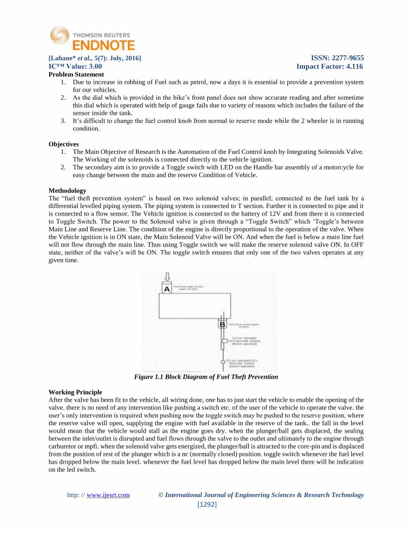
The “fuel theft prevention system” is based on two solenoid valves; in parallel; connected to the fuel tank by a
differential levelled piping system. The piping system is connected to T section. Further it is connected to pipe and it
is connected to a flow sensor. The Vehicle ignition is connected to the battery of 12V and from there it is connected
to Toggle Switch. The power to the Solenoid valve is given through a “Toggle Switch” which ‘Toggle’s between
Main Line and Reserve Line. The condition of the engine is directly proportional to the operation of the valve. When
the Vehicle ignition is in ON state, the Main Solenoid Valve will be ON. And when the fuel is below a main line fuel
will not flow through the main line. Thus using Toggle switch we will make the reserve solenoid valve ON. In OFF
state, neither of the valve’s will be ON. The toggle switch ensures that only one of the two valves operates at any
given time.
Figure 1.1 Block Diagram of Fuel Theft Prevention
Working Principle
After the valve has been fit to the vehicle, all wiring done, one has to just start the vehicle to enable the opening of the
valve. there is no need of any intervention like pushing a switch etc. of the user of the vehicle to operate the valve. the
user’s only intervention is required when pushing now the toggle switch may be pushed to the reserve position, where
the reserve valve will open, supplying the engine with fuel available in the reserve of the tank.. the fall in the level
would mean that the vehicle would stall as the engine goes dry. when the plunger/ball gets displaced, the sealing
between the inlet/outlet is disrupted and fuel flows through the valve to the outlet and ultimately to the engine through
carburetor or mpfi. when the solenoid valve gets energized, the plunger/ball is attracted to the core-pin and is displaced
from the position of rest of the plunger which is a nc (normally closed) position. toggle switch whenever the fuel level
has dropped below the main level. whenever the fuel level has dropped below the main level there will be indication
on the led switch.

[Lahane* et al., 5(7): July, 2016] ISSN: 2277-9655
IC™ Value: 3.00 Impact Factor: 4.116
http: // www.ijesrt.com © International Journal of Engineering Sciences & Research Technology
[1293]
Figure 1.2 Project Model
LITERATURE REVIEW Survey of Existing Product In Market
Figure 2.1: Standard Fuel Cock
The Bajaj pulsar fuel tap is the standard product available in the market for all pulsar motor bikes. In our project we
have considered this type of standard fuel tap as the sample specimen for our design requirements. Costing anywhere
between Rs.125/- to Rs.250/- for an original fuel cock, it gives us a control of the flow of the fuel from the tank to the
engine. When a vehicle is stationary, there is no point in having the engine running. If the engine is not running, there
is no point in fuel flowing from the tank to the engine! A knob is provided in the fuel cock which can be turned to
“OFF” state so that the fuel does not flow to the engine. When the level of the fuel has dropped beyond a certain level

[Lahane* et al., 5(7): July, 2016] ISSN: 2277-9655
IC™ Value: 3.00 Impact Factor: 4.116
http: // www.ijesrt.com © International Journal of Engineering Sciences & Research Technology
[1294]
wherein it becomes important to fill up the tank, the engine stalls! This is because While in “ON” state, No more fuel
can pass into the engine.
There is fuel existing in the tank, But as no fuel flows into the engine, the vehicle tends to stall. The knob of the fuel
cock has to be turned to the “Reserve” state so that the remaining fuel can now pass. Ideally, a person should have the
tank filled up so that there may not be a “DRY FUEL TANK” condition. A person needs to physically bring his hand
below the fuel Main Fuel Line Reserve Fuel Line Fuel outlet Fuel Control Knob Tank to change over the position of
the knob. This may become a dangerous proposition when the vehicle is “running” and a switch over from “ON” to
“RESERVE” has to be made while the vehicle is in “running” condition.
Components Of Existing Product
The components of the selected sample product are:
Figure 2.2 : Existing Fuel cock Components
In general, there are three basic types of contact modellingMain Line: The plastic pipe having a mesh (filter) through
with the fuel passes when the knob is in ‘ON’ mode.
Reserve Line: The plastic pipe having a mesh (filter) through with the fuel passes when the knob is in ‘RESERVE’
mode.
Fuel Outlet: This is a brass pipe outlet from the fuel tap which connects to the carburetor. It is observed to have an
orifice diameter of 3.0 mm.
Fuel Control Knob : This knob is responsible for the changing between the main and the reserve fuel line. This also
has an ‘OFF’ feature which prevents the fuel to enter the carburettor. Hero Honda CD100 is seen to have the highest
mileage. It was observed that manufactures have various outlet orifice diameters which also have a role to play in
mileage.

[Lahane* et al., 5(7): July, 2016] ISSN: 2277-9655
IC™ Value: 3.00 Impact Factor: 4.116
http: // www.ijesrt.com © International Journal of Engineering Sciences & Research Technology
[1295]
Market survey of petrol lock
Table 2.1 Market survey of petrol lock
Market Survey Conclusion
The Brands considered for survey where Bajaj Pulsar, TVS victor, Hero Honda CD100, Pricol (Automatic)
As per market survey manufactures have various outlet diameters which also have roll to play in mileage.
HERO HONDA CD100 is seen to have highest mileage and smallest orifice diameter.
Standard material used is Mild Steel or aluminum Body. Some alternations were seen depending on cost of
bike
FUELTHEFTPROCESS IN TWOWHEELERS
Figure3.1FueltheftsProcess

[Lahane* et al., 5(7): July, 2016] ISSN: 2277-9655
IC™ Value: 3.00 Impact Factor: 4.116
http: // www.ijesrt.com © International Journal of Engineering Sciences & Research Technology
[1296]
Most of the lower end bikes in India are susceptible to fuel theft. An average fuel tank contains approximately Rs1000-
1200 worth of fuel. This makes it very important for the manufacture’s to safeguard this aspect. The simple fuel theft
process is illustrated above in 2 steps with just a pair of scissors and bottle.
STEP 1
Disconnect/Cut the pipe from the fuel tap to the carburettor and suck the fuel till it flows. Make sure the fuel tap is in
the “ON” or “RESERVE” mode.
STEP 2
Place the pipe in the bottle till enough fuel is siphoned. Put the pipe back to the carburettor.
SOLENOID VALVE
A solenoid valve is an electronically operated device. It is used to control the flow of liquids or gases in a positive,
fully-closed or fully-open mode. The valve is commonly used to replace a manual valve or where remote control is
desirable. A solenoid is operated by opening and closing an orifice in a valve body that permits or prevents flow
through the valve. The orifice is opened or closed through the use of a plunger that is raised or lowered within a sleeve
tube by energizing the coil. The bottom of the plunger contains a compatible sealing material, which closes off the
orifice in the body, stopping flow through the valve. The solenoid assembly consists of a coil, plunger, and sleeve
assembly. In a normally closed valve, a plunger return spring holds the plunger against the orifice, preventing flow
through the valve. When the coil is energized, a magnetic field is produced, raising the plunger and allowing flow
through the valve. In a normally open valve, when the coil is energized, the plunger seals off the orifice, stopping flow
through the valve. Two-way solenoid valve. A two-way valve controls flow in one direction. It may be directoperated
or pilot operated. [10]
Figure 4.2 Working of Solenoid Valve
Input Side: The input side to the solenoid stands for the petrol tank in our project.
Diaphragm/Plunger: This is a either a rubber or a metallic stopper used to regulate the flow of the liquid.
Pressure Chamber: This is the area where the fluid is filled irrespective of the plunger being open or closed.
Pressure Relief: This area get flow when the plunger is moved due to the action of the electromagnetic solenoid
valve.
Solenoid: This is a coil of wire, through which when current is passed actuated the plunger and moves it from its
normal position.
Outlet: The fluid flows through this part when the flow is allowed by the solenoid.

[Lahane* et al., 5(7): July, 2016] ISSN: 2277-9655
IC™ Value: 3.00 Impact Factor: 4.116
http: // www.ijesrt.com © International Journal of Engineering Sciences & Research Technology
[1297]
Types of Solenoid Valve
Direct Operated Solenoid Valves
Direct operated solenoid valves function to directly open or close the main valve orifice, which is the only flow path
in the valve. Direct operated valves are used in systems requiring low flow capacities or in applications with low
pressure differential across the valve orifice. The sealing surface that opens and closes the main valve orifice is
connected to the solenoid plunger. The valve operates from zero pressure differentials to maximum rated pressure
differential (MOPD) regardless of line pressure. Pressure drop across the valve is not required to hold the valve open.
Figure 4.3 Two Way Direct Operated Solenoid Valve
Pilot Operated Valves
Pilot operated valves are the most widely used solenoid valves. Pilot operated valves utilize system line pressure to
open and close the main orifice in the valve body. In a piston-style valve, the main orifice is held closed with a piston
seal pressed against the main orifice by the combined fluid pressure and spring pressure. In a normally closed valve,
the piston is shifted or opened when the pilot operator is energized. This allows fluid behind the piston to evacuate
through the valve outlet. At this point, the system line pressure moves the piston, opening the main orifice of the valve
allowing high capacity flow through the valve. When energizing the coil of a normally open valve, fluid pressure
builds up behind the piston, forcing the piston to seal the main orifice of the valve.
Normally Closed (NC)
A solenoid valves normally closed (abbreviated-NC) if there is no flow across the valve in its resting position (with
no current on the solenoid contacts).
Figure 4.4 Symbol of Normally Closed Valve
Normally Open (NO)
A solenoid valve is said to be “normally open” (abbreviated NO) when it enables fluid to pass in its resting position[8]

[Lahane* et al., 5(7): July, 2016] ISSN: 2277-9655
IC™ Value: 3.00 Impact Factor: 4.116
http: // www.ijesrt.com © International Journal of Engineering Sciences & Research Technology
[1298]
Figure 4.5 Symbol of Normally Open Valve
SELECTION OF SOLENOID VALVE
2W Brass Series 2-Way Direct Acting Solenoid Valve Normally Closed
Table 5.1 2W Brass Series of Solenoid Valve
Where,
2W- 2Way Direct Acting
025- Orifice
08- Pipe Size
DC 12V-Available Voltage
SELECTION GUIDELINES General purpose solenoid valves are used with a wide variety of liquids and gases in a broad spectrum of applications.
Rating the valve capacity in terms which apply to all operating conditions is accomplished by determining the “flow
factor” (Cv) of the valve. The Cv value is the number of U.S. gallons of water at 16°C (60°F) per minute that, when
flowing through the valve, causes a pressure drop of 1 psi. This measure of capacity is stated for every model in
catalogue. There are five main parameters to consider when selecting a valve: Cv, media compatibility, pressure,
temperature, andprocess fitting. For each of these parameters, maximum values are listed for each valve. To choose
the correct valve, compare each parameter and check that it is less than the maximum value listed.
Coefficient of Discharge: It is the Ratio of actual discharge to theoretical discharge.i.e, the ratio of the mass flow rate
at the discharge end of nozzle of the nozzle to that of an ideal nozzle which expands an identical working fluid from
the same exit pressures.
LIQUID APPLICATIONS For most applications, liquids are considered incompressible, and
only the following factors need be considered in sizing a valve:
Cv = Coefficient of Discharge of valve
Q = Flow expressed in U.S. gallons per minute (GPM)
P = Pressure drop across the valve (P1-P2)
P1 = Inlet Pressure (psig)
P2 = Outlet Pressure (psig)
G = Specific Gravity of the fluid
(G = 1.0 for water at 16°C (60°F)
These factors are related according to the equation:

[Lahane* et al., 5(7): July, 2016] ISSN: 2277-9655
IC™ Value: 3.00 Impact Factor: 4.116
http: // www.ijesrt.com © International Journal of Engineering Sciences & Research Technology
[1299]
CFD analysis of solenoid valve
A Three dimensional numerical simulation has been carried out to predict the discharge coefficient of a solenoid valve.
Solenoid valve consist of solenoid operated piston which opens and closes based on current input to open or close the
valve. When the piston is lifted fluid flows from high to low pressure side.
CFD model Assumptions
The internal fluid volume of the solenoid valve is used for CFD analysis. Valve is assumed to be fully opened. That
is the piston is lifted to the top most position under this condition the fluid flows from high pressure side to low
pressure side.
Boundary Condition
The Inlet to solenoid valve is from a tank filled with fluid. The inlet pressure is defined based on the height of fuel in
the tank. In this case pressure is assumed as 1000pa based of height of 10 cm.
Inlet Pressure = Density of liquid x Gravitational Accln x height of in the tank.
The outlet pressure is maintained at 0 Pa.
No slip velocity condition is applied at the valve regions.
Figure 5.1 CAD Model of Solenoid Valve
Meshing
The fluid domain is meshing using an unstructured polyhedral mesh. The total number of nodes is 228572.
Domain – fluid Domain - valve
Type Cell Type solid
Domain Boundaries Domain
fluid Boundary - contact region
Boundary -contact_region
Type INTERFACE Type INTERFACE

[Lahane* et al., 5(7): July, 2016] ISSN: 2277-9655
IC™ Value: 3.00 Impact Factor: 4.116
http: // www.ijesrt.com © International Journal of Engineering Sciences & Research Technology
[1300]
Boundary - inlet Valve Boundary - wall valve
Type MASS-FLOW-INLET Type WALL
Boundary - outlet
Type PRESSURE-OUTLET
Table 5.2 Boundary Conditions for 0.12kg/s mass flow rate
Figure 5.2 meshing of solenoid valve
Results of Analysis
Figure5.3 Velocity analysis of solenoid valve for 6.25mm Pipe Size
Figure.5.4 Pressure analysis of solenoid valve for 6.25mm pipe size

[Lahane* et al., 5(7): July, 2016] ISSN: 2277-9655
IC™ Value: 3.00 Impact Factor: 4.116
http: // www.ijesrt.com © International Journal of Engineering Sciences & Research Technology
[1301]
Figure 5.5 velocity analysis of solenoid valve for 10mm Pipe Size
Figure.5.6 Pressure analysis of solenoid valve for 10mm Pipe Size
Figure5.7 velocity analysis of solenoid valve for 12.5mm Pipe Size

[Lahane* et al., 5(7): July, 2016] ISSN: 2277-9655
IC™ Value: 3.00 Impact Factor: 4.116
http: // www.ijesrt.com © International Journal of Engineering Sciences & Research Technology
[1302]
Figure5.8 Pressure analysis of solenoid valve for 12.5mm Pipe Size
Formula
Calculations for 6.25mm pipe size:
Given; Pressure Difference ΔP = 0.2844psi ( From Cfd)
Specific Gravity G = 0.737 (For Petrol)
Mass Flow Rate= 0.12 kg/s = 0.1905 GPM
Therefore
Cv = 0.1905*(0.737/0.2844)1/2
Cv = 0.3066
Calculations for 10mm pipe size :
Given; Pressure Difference ΔP = 0.1165psi ( From Cfd)
Specific Gravity G = 0.737 (For Petrol)
Mass Flow Rate= 0.12 kg/s = 0.1905 GPM
Therefore
Cv = 0.1905*(0.737/0.1165)1/2
Cv = 0..4791
Calculations for 12.5mm pipe size:
Given; Pressure Difference ΔP = 0.042psi ( From Cfd)
Specific Gravity G = 0.737 (For Petrol)
Mass Flow Rate= 0.12 kg/s = 0.1905 GPM
Therefore
Cv = 0.1905*(0.737/0.042)1/2
Cv = 0.798

[Lahane* et al., 5(7): July, 2016] ISSN: 2277-9655
IC™ Value: 3.00 Impact Factor: 4.116
http: // www.ijesrt.com © International Journal of Engineering Sciences & Research Technology
[1303]
Selected Solenoid Valve
Figure 5.9 Model of 2W-025-08 Solenoid Valve
Specifications:
Model 2W-025-08
Port size 1/4" NPT thread female
inlet and outlet ports
Voltage 12VDC
Build
Material
Brass
Operation
mode
Normally Closed
Fluid
Viscosity
Low Viscosity Fluids,
Vacuum (below 20 cst)
Pressure
Limits
0-1MPa
Temperature 5 -80C
Seal
Material
NBR (Nitrile Butadiene
Rubber)
Flow Pore
Size
2.5mm
Net weight 300g
Start current 2A
Table 5.3 Specification of 2W-025-08 Solenoid Valve

[Lahane* et al., 5(7): July, 2016] ISSN: 2277-9655
IC™ Value: 3.00 Impact Factor: 4.116
http: // www.ijesrt.com © International Journal of Engineering Sciences & Research Technology
[1304]
Design of Solenoid Valve
Figure 5.10 Front View
Figure 5.11 Side View
Figure 5.12 Top View

[Lahane* et al., 5(7): July, 2016] ISSN: 2277-9655
IC™ Value: 3.00 Impact Factor: 4.116
http: // www.ijesrt.com © International Journal of Engineering Sciences & Research Technology
[1305]
ARDUINO Arduino UNO R3 board with DIP ATmega328
The Arduino Uno Rev3 is a micro controller board based on the ATmega328 (datasheet). It has 14 digital input/output
pins (of which 6 can be used as PWM outputs), 6 analog inputs, a 16 MHz crystal oscillator, a USB connection, a
power jack, an ICSP header, and a reset button. It contains everything needed to support the microcontroller; simply
connect it to a computer with a USB cable or power it with a AC-to-DC adapter or battery to get started. The Uno
differs from all preceding boards in that it does not use the FTDI USB-to-serial driver chip. Instead, it features the
Atmega8U2 programmed as a USB-to-serial converter."Uno" means one in Italian and is named to mark the upcoming
release of Arduino 1.0. The Uno and version 1.0 will be the reference versions of Arduino, moving forward. The Uno
is the latest in a series of USB Arduino boards, and the reference model for the Arduino platform. Microcontroller
ATmega328 Operating Voltage 5V Input Voltage (recommended) 7-12V Input Voltage (limits) 6-20V Digital I/O
Pins 14 (of which 6 provide PWM output) Analog Input Pins 6 DC Current per I/O Pin 40 mA DC Current for 3.3V
Pin 50 mA Flash Memory 32 KB of which 0.5 KB used by boot loader SRAM 2 KB EEPROM 1 KB Clock Speed 16
MHz.[1][2][3].
Figure 6.1 Arduino UNO R3 Board
Technical Specification
Microcontroller ATmega328P
Operating Voltage 5V
Input Voltage (recommended) 7-12V
Input Voltage (limit) 6-20V
Digital I/O Pins 14 (of which 6
provide PWM output)
PWM Digital I/O Pins 6
Analog Input Pins 6
DC Current per I/O Pin 20 mA
DC Current for 3.3V Pin 50 mA
Flash Memory 32 KB
(ATmega328P)
of which 0.5 KB used
by bootloader
SRAM 2 KB (ATmega328P)
EEPROM 1 KB (ATmega328P)
Clock Speed 16 MHz
Length 68.6 mm
Width 53.4 mm
Table 6.1 Technical Specification of Arduino

[Lahane* et al., 5(7): July, 2016] ISSN: 2277-9655
IC™ Value: 3.00 Impact Factor: 4.116
http: // www.ijesrt.com © International Journal of Engineering Sciences & Research Technology
[1306]
FLOW SENSOR YF-S201 Hall Effect Water Flow Meter / Sensor:
This sensor sits in line with your water line and contains a pinwheel sensor to measure how much liquid has moved
through it. There's an integrated magnetic Hall Effect sensor that outputs an electrical pulse with every revolution.
The Hall Effect sensor is sealed from the water pipe and allows the sensor to stay safe and dry. The sensor comes with
three wires: red (5-24VDC power), black (ground) and yellow (Hall Effect pulse output). By counting the pulses from
the output of the sensor, you can easily calculate water flow. Each pulse is approximately 2.25 millilitres. Note this
isn't a precision sensor, and the pulse rate does vary a bit depending on the flow rate, fluid pressure and sensor
orientation. It will need careful calibration if better than 10% precision is required. However, it’s great for basic
measurement tasks! We have as example Arduino sketch that can be used to quickly test the sensor; it will calculate
the approximate flow of water in litres/hour.
The pulse signal is a simple square wave so its quite easy to log and convert into litres per minute using the following
formula.[6]
Pulse frequency (Hz) / 7.5 = flow rate in L/min.
Figure 7.1 Flow Sensor YF-S201
Step 1: Connecting the Arduino flow rate sensor
Here, the connections required for this flow rate sensor with respect to Arduino is very minimal. There are only three
wires coming from the flow rate sensor. The 5V Vcc (Red wire), The Gnd (Black wire), and the signal/pulse (Usually
yellow) line. Connect the Vcc and Gnd of the flow meter to the arduino’s Vcc and Gnd. The pulse line of the flow
rate sensor is connected to arduino’s digital pin 2. The arduino’s digital pin 2 serves as an external interrupt pin
(interrupt pin 0). Now you have hooked up your flow meter to the arduino.
Step 2: Upload the flow meter code to the arduino and measure water flow rate
Upload the code to your arduino : Flow Meter Code. Here the code uses an external interrupt on arduino’s digital pin
2. This is used to read the pulses coming from the flow meter. When arduino detects the pulse, it immediately
triggers the pulse Counter () function. This function then counts the total number of pulses. In this arduino flow rate
sensor, for every litre of liquid passing through it per minute it outputs about 4.5 pulses. Thus dividing the total pulse
count obtained by 4.5 will give you the total amount of liquid passing through it in litres/minute. Further dividing it
by 60 will give you the flow rate in litres/hr. And hence the total amount or quantity of water/liquid that has passed
through it. The sensor is accurate to within 3%.[5]

[Lahane* et al., 5(7): July, 2016] ISSN: 2277-9655
IC™ Value: 3.00 Impact Factor: 4.116
http: // www.ijesrt.com © International Journal of Engineering Sciences & Research Technology
[1307]
Figure 7.2 Connection of Arduino with Flow Sensor
OTHER COMPONENTS USED IN PROJECT Fuel Tank
Figure 8.1 Yamaha Crux R5tm1 Series
Ignition Switch
Figure 8.2 Ignition Switch

[Lahane* et al., 5(7): July, 2016] ISSN: 2277-9655
IC™ Value: 3.00 Impact Factor: 4.116
http: // www.ijesrt.com © International Journal of Engineering Sciences & Research Technology
[1308]
Led Screen
Basic 20x4 Character LCD - Black on Green 5V
LCD-00256
Figure 8.3 Led Displays
Description: This is a basic 20 character by 4 line display. Utilizes the extremely common HD44780 parallel interface
chipset. Includes LED backlight. [7]
Others
Other components include Wires, Pipes, Relays, Battery, Connectors, T- Connectors bike grips Etc.
TESTING OF PROJECT 9.1 Testing of LED Display
Aim: To Checking the functioning of the LED display from the handle bar with the entire electrical circuit connected.
Apparatus: Two Solenoid And Ignition switch, handle bar switch and battery.
Diagram:
Figure 9.1 Fuel Low Indications on LED Display
Working procedure:
Turn the ignition “On” and after that turn the toggle switch towards the main fuel line. The process is repeated for the
reserve line solenoid
Observation:
A LED display Shows “THE FUEL IS LOW” which signifies that we have to change the fuel flow from normal to
reserve condition.
Result:
Solenoid and switch set working.
Testing of Working of Solenoid Valve
Aim: To Check the fitment to the tank of the solenoid and to check the individual flow from pipe on actuation of the
Solenoid
Apparatus: Two Solenoid and Ignition switch, handlebar switch, battery, pipe, Funnel, Transparent pipes, Petrol tank
(Yamaha Crux), M6 bolts, washers, petrol.

[Lahane* et al., 5(7): July, 2016] ISSN: 2277-9655
IC™ Value: 3.00 Impact Factor: 4.116
http: // www.ijesrt.com © International Journal of Engineering Sciences & Research Technology
[1309]
Working procedure:
Fill the petrol tank with four litres of petrol till the main fuel line is completely immersed.
Turn the ignition “On” and turn the toggle switch towards the main fuel line solenoid. This should be followed by
petrol flowing only through Main transparent pipe till the flow stops; this indicates that the level of petrol has fallen
below the main line.
Now the reserve line solenoid should be switched on, by petrol flowing through reserve transparent pipe. When the
ignition is turned off there should be no flow.
Observation:
Flow is observed though the individual pipes. No flow condition on removal of the key.
Slight leakage observed on the mounting points.
Result: Solenoids working and connected to ignition.
Flow Rate Testing
Aim: To determine the flow of petrol though the drilled 2.5mm orifice Measure the fuel output
Apparatus: Two Solenoid, Ignition switch, handlebar switch, battery, pipe, Funnel, Transparent pipes, Petrol tank
(Yahama Crux), petrol, Stopwatch, Measuring flask
Diagram:
Figure 9.2 Flow Rate Testing
Working Process:
Fill petrol in the fuel tank till the tank has reached maximum capacity and connect the battery. Turn the ignition on
and switch on switch to the main line solenoid. Observe the flow till it stops by itself. Record the time Switch to the
reserve solenoid and record the time till the flow stops. Turn ignition off and check the No Flow condition.
Observations:
A small leakage was experienced through the mounting points. The solenoid get heated after 2 hours of continues
functioning. Excess air bubbles are observed towards the end of flow through the pipe. This is characterized on the
running bike as knocking when the fuel levels are low. Rubber washers found inadequate for sealing criteria due to
reaction with petrol. Fibre washer used to control the flow. The below table show the flow through the Main Line for
One litre of petrol. Average time is 4 minutes and 10seconds. The leakage of 5ml.

[Lahane* et al., 5(7): July, 2016] ISSN: 2277-9655
IC™ Value: 3.00 Impact Factor: 4.116
http: // www.ijesrt.com © International Journal of Engineering Sciences & Research Technology
[1310]
Flow rate test results:
Table 9.1 FlowRateTestResult
Calculations:
Formula: By Bernoulli’s Equation When Area is same in Orifice Plate
𝑚 = 𝜌𝑄 = 𝐶𝑣 𝑋 𝐴 𝑋√2𝜌∆𝑃
Where,
CV = Discharge Coefficient
A =Area of Duct
M = Mass Flow Rate (From Test)
𝝆 = Density of Petrol
ΔP = Pressure Drop
1. Density = 737 kg/m3
Duct Diameter= 6.25mm
Duct Area = 30.679 mm2
Mass Flow Rate = 3.55min
CV = (737 X 3.55 ) / (30.679)(2 X 737 X 2000)1/2
CV = 0.3104
2. Pressure Drop = 2000pa
Density = 737 kg/m3
Duct Diameter= 6.25mm
Duct Area = 30.679 mm2
Mass Flow Rate = 3.48min
CV = (737 X 3.48) / (30.679) (2 X 737 X 2000)1/2
CV = 0.3043
3. Pressure Drop = 2000pa
Density = 737 kg/m3
Duct Diameter= 6.25mm
Duct Area = 30.679 mm2
Mass Flow Rate = 3.58min
CV = (737 X 3.55) / (30.679) (2 X 737 X 2000)1/2
CV = 0.3130
4. Pressure Drop = 2000pa
Density = 737 kg/m3
Duct Diameter= 6.25mm
Duct Area = 30.679 mm2
Mass Flow Rate = 3.45min
CV = (737 X 3.55) / (30.679)(2 X 737 X 2000)1/2
CV = 0.3017
5. Pressure Drop = 2000pa
Density = 737 kg/m3
Duct Diameter= 6.25mm

[Lahane* et al., 5(7): July, 2016] ISSN: 2277-9655
IC™ Value: 3.00 Impact Factor: 4.116
http: // www.ijesrt.com © International Journal of Engineering Sciences & Research Technology
[1311]
Duct Area = 30.679 mm2
Mass Flow Rate = 3.49min
CV = (737 X 3.55) / (30.679)(2 X 737 X 2000)1/2
CV = 0.3052
SR
No
Analytical CV Practical CV % Error
1
0.3066
0.3104 0.38%
2 0.3043 0.23%
3 0.3130 0.64%
4 0.3017 0.49%
5 0.3052 0.14%
Table 9.2 Results of flow rate testing
RESULT AND DISCUSSION Here Our System is work successfully to avoid the accidents which is happened on the roads a we have seen the
accident survey. A retched is device which is used in vehicles over a few decades and when a vehicle is negotiating a
turn, the outside wheel travels a greater distance and turns faster than the inside wheel. The ratchet gear is the device
transmitting the power to each wheel, allows one wheel to turn faster than the other.
Degrees of Automation are of two types
Full Automation
Semi Automation
In semi automation a combination of manual effort and mechanical power is required whereas in full automation
human participation is very negligible. It will be very beneficial to control the accidents by using the Automatic
Breaking system mechanism.
Advantages:
Fuel theft control
Efficient
Fit and forget system
Completely Remove Petrol Lock Concept
User Friendly
Automatic
No Need to Worry about Fuel Level
Applications:
Used in Two Wheeler Vehicles
CONCLUSION 1. By providing Fuel theft prevention system we have done prevention of fuel theft which is one of essential
and costly thing in our two wheelers
2. As the dial which is provided in the bike’s front panel does not show accurate reading and after sometime
this dial which is operated with help of gauge fails due to variety of reasons which includes the failure of the
sensor inside the tank. Hence we have designed Digital indicating panel that will show us accurate reading
of fuel in the tank.
3. We also aimed our project to ease the use of the system which successfully toggles the main and the reserve
line. With this the chances of the rider to meet and accident is reduced marginally.
4. This system can be reduced in size to about half the current size if it moves to the research stage. This can be
achieved by procuring solenoids which are smaller in size.

[Lahane* et al., 5(7): July, 2016] ISSN: 2277-9655
IC™ Value: 3.00 Impact Factor: 4.116
http: // www.ijesrt.com © International Journal of Engineering Sciences & Research Technology
[1312]
In this system fuel theft is difficult as it is locked by heavy body covering of the bike. The middle class people will
have to burn a hole in their pocket if they want to enjoy this modification. Otherwise they will have to keep on suffering
the consequences of poor design of fuel taps.
FUTURE SCOPE 1. Reduction ofsizeof thesolenoid valveto integrateinto the machinedblockis themost importantaspect ofthe
designmodifications.
2. Various levels oftestingshould bedonebefore integratingit into the machineblock tocheckfor robustness
andrigidityofmanufacture.
3. In Future we can manufacture a tank which has inbuilt solenoid valve.
4. In future we can use an alarm for indicating fuel low indication.
REFERENCES
1. Boote J & Mathews, Qualitative market Research:- An international Journal (A) 2(1) 1999 pg(15-21)
2. Bulmer, Qualitative sociology,M(1982)5 Summer (269-285)
3. Guillemin,M&Gillam L, Ethics reflexivity, & Qualitative inquiry vol 10 2004 pg (261-280)
4. ShigionCai&HalukToral, “Flowrate measurement in air – water horizontal pipeline by neural network”,
International Joint Conference on Neural Network 2013 pg (213-216)
5. Santhosh KV & BK Roy “An intelligent flow measurement technique”, international journal of control and
automation vol 5 2012 pp (185-196)
6. K Foram M. Anubhav&M,pritish “Display message on notice board”,Advance in electronic and electric
engineering vol 3 2013 pp (827-832)
7. Gholamreza.V&Donath M =, Dynamic Feedback Linearization of electro hydraulically actuated control
system , ASME journal of dynamic system measuremen and control, Volume 117,1995 pg 468-477
8. Jiing-Yih Lai And Yuan –Rong Chen , Adaptive Flowrate control of a Hydraulic proportional valve JSME
international journal (Series 3), V135, N4,1992, pg 582
9. I. Dulk and T. Kovacshazy, “Modelling of a linear proportional electromagnetic actuator and possibilities
of sensor less plunger position estimation,” Instrumentation and Measurement Technology Conference
(I2MTC), IEEE International, 2012,pp. 89–93.
10. Shanmuganathan J, B.C.Kavitha “Tracking and theft prevention system for two wheeler” International
Journal of Engineering Trends and Technology (IJETT) – Volume 21 Number 7 – March 2015 pg 355-358