Analyser Control Unit Mk4 Operating...
28
Analyser Control Unit Mk4 Operating Manual
Transcript of Analyser Control Unit Mk4 Operating...

Analyser Control Unit Mk4
Operating Manual
Analyser Control Unit Mk4 Operating Manual
Page 2 PROCAL ANALYTICS LTD Issue 2
Procal Analytics Limited
Published by Procal Analytics Limited.
All possible care has been taken in the preparation of this publication, but Procal Analytics, its agents and distributors, accept no liability for any inaccuracies that may be found. This manual reflects the state of the product at the issue date below, but further enhancements may mean that the manual does not fully reflect your particular system.
Procal Analytics Limited reserves the right to make changes without notice both to this publication and the products which it describes.
No part of this publication may be reproduced, stored in a retrieval system or transmitted in any form or by any means electronic, mechanical, photocopying, recording or otherwise without the express prior written permission of the copyright holder.
Part Number 7-3005-04 Issue 2 August 2010
© Procal Analytics Limited 2010
Procal Analytics Limited 5 Maxwell Road Woodston PETERBOROUGH PE2 7HU United Kingdom
PROCAL, PULSI and XSENS are trademarks of Procal Analytics Limited.
Contents
Issue 2 PROCAL ANALYTICS LTD Page 3
Pulsi Analyser Control Unit Mk4…………………………………………………………. ..I Operating Manual………………………………………………………………………….…I
Procal Analytics Limited………………………………………………………………. ..II Content…………………………………………………………………………………. ..III
1 Introduction……………………………………………………………………………….. .1-1 About this manual……………………………………………………………………… .1-1 About the Pulsi Analyser Series……………………………………………………….. .1-1 About the Procal 5000 Analyser ……………………………………………………….. .1-1 Repair Policy…………………………………………………………………………….1-1 Document Conventions………………………………………………………………… .1-2 Abbreviations…………………………………………………………………….. .1-2 Lists………………………………………………………………………………. .1-2 Figures……………………………………………………………………………. .1-2 Italics……………………………………………………………………………….1-2 Dimensions……………………………………………………………………….. .1-2
Pulsi Analyser – an overview……………………………………………………………1-3 Further Information…………………………………………………………………….. .1-4
2 Technical specification……………………………………………………………………..2-1 Introduction……………………………………………………………………………....2-1 ACU Specification……………………………………………………………………….2-1 ACU to Analyser interconnection………………………………………………………..2-3
Local PSU to Analyser……………………………………………………………..2-3 ACU to Analyser Cable (Communications)……………………………………......2-3 3 Installation…………………………………………………………………………………..3-1
Warnings…………………………………………………………………………....3-1 Unpack the system components……………………………………………………………. ..3-1 Fitting and preparing the ACU……………………………………………………………….3-1 WARNING……………………………………………………………………….. ..3-1 Gaining Internal access to the ACU………………………………………………..3-1 Preparing cables for the ACU…………………………………………………….. ..3-4 Feeding cables into the ACU…………………………………………………….…3-6 Connecting the system to the electrical supply…………………………………….3-6
Connecting to Analyser(s)………………………………………………………... .3-7 Connecting to External Communication (Digital)…………………………………3-8 Connecting Lan – Ethernet……………………………………………………….. .3-8 Connecting Printer Memory Stick………………………………………………....3-8 Connecting - Analogue / Digital I/O……………………………………………….3-9 Preparing cables for the I/O………………………………………………………. .3-11 System configuration……………………………………………………………... .3-13 Module configuration…………………………………………………………….. .3-13 Operation…………………………………………………………………………. .3-14 Connecting the system to the supply……………………………………………... .3-14
4 Software Operation and configuring………………………………………………….. .4-1 Use Analyser Control For Windows For Network – …………………………….. .4-1 Operating manual 7-3038 supplied with ACU

Analyser Control Unit Mk4 Operating Manual
Page 4 PROCAL ANALYTICS LTD Issue 2
Page left intentionally blank
Issue 2 PROCAL ANALYTICS LTD Page 1-1
1 Introduction About this manual
This manual is intended to assist the user in the safe and efficient installation, operation and maintenance of the PULSI Analyser series of process gas analysers. It has been written in accordance with the requirements of British Standard BS4884 Technical manuals Part 1: 1992.
It is split into a number of sections. Introduction (this section) gives a brief overview of both this manual and the systems which it describes, together with sources of further information and product support. Installation gives pre-installation information and goes on to describe how the Control Unit of a PULSI Analyser system is installed.
About the PULSI Analyser series
The PULSI Analyser series is a range of high-performance gas process analyser systems. These systems are intended to be used for measuring gas concentrations, particularly in continuous industrial processes and flue stacks.
Every system includes up to four PULSI Analysers and a PROCAL Analyser Control Unit.
This technical manual describes primarily the Analyser Control Unit. A separate manual exists for
Each type of Analyser, eg P200.
Software loaded on the Analyser Control Unit (ACWn) 7- 3038
About the Procal 5000 Analyser.
The description and operation of the Procal 5000 Analyser is to be found in its own manual, part number 7-3512-00. For connection of the P5000 to an ACU, with and without other Analyser Units, refer to the installation drawing number 7-4951-11.
Repair Policy
Procal Analytics recommends that repairs to the PULSI Analyser system or Procal 5000 system are only made by its own trained support staff, or by those of its distributors world-wide.
If you have the necessary technical qualifications, training and experience you may wish to make straightforward repairs in-house. A spares list is given for this purpose. However, you should note that if a repair is incorrectly carried out, this may void or limit the warranty on the system. You should also note that this manual is not intended to describe fault-finding or repair down to component level.
Analyser Control Unit Mk4 Operating Manual
Page 1-2 PROCAL ANALYTICS LTD Issue 2
Documentation Conventions
Abbreviations Within this manual, the following abbreviations are used:
■ ACU Analyser Control Unit
■ ACWn Analyser Control for Windows Network – Software
■ AVU Auto Verification Unit
■ IR Infra red
■ ISH In-Situ Heater
■ AU Analyser Unit
■ PSU Power Supply Unit
■ UV Ultra violet
Lists Often in this manual, instructions or information are presented in list form. Use of black squares ■■■ indicates that there is no special order to the instructions or information. However, when instructions are numbered, it is important that the individual instructions or points are followed sequentially.
Figures Figures in the text are always numbered in the form Figure X-Y, where X is the section number, and Y is the sequential figure number within that section. For example, Figure 3-2 is the second figure in section 3. When a figure reference is in brackets (Figure 9-4), this refers you to that figure, usually to confirm the location of a component, control or indicator.
Italics Paragraphs in italics usually indicate background information which may be of benefit to the reader. Groups of words in italics are usually cross-referring the reader to a section or sub-section by name.
Dimensions All dimensions in this Operating Manual are in mm (millimetres) unless otherwise indicated.
PULSI Analyser system - an overview
At each Analyser, the concentrations of up to six gases may be measured. In addition, up to three analogue inputs can be accepted as 0 - 20 mA, 4 - 20 mA, 0 - 5 V or 1 - 5 V signals
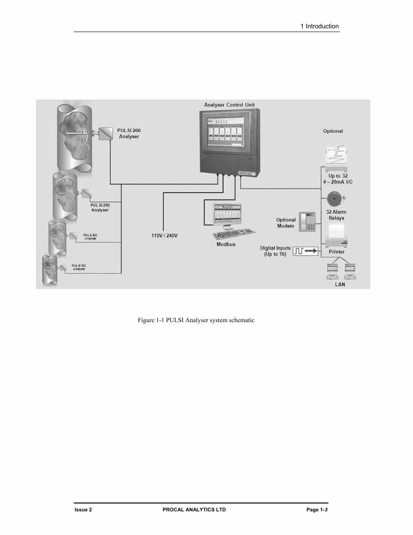
A schematic diagram of a typical PULSI Analyser system appears in Figure 1-1. This shows the various interconnections between different parts of the system, and some of the external devices that may be connected to the Analyser Control Unit.
Each Analyser functions independently but each is controlled by the Analyser Control Unit, which collects data from all of the Analysers. The Analyser Control Unit displays and stores readings obtained from the Analysers.
1 Introduction
Issue 2 PROCAL ANALYTICS LTD Page 1-3
Figure 1-1 PULSI Analyser system schematic
Analyser Control Unit Mk4 Operating Manual
Page 1-4 PROCAL ANALYTICS LTD Issue 2
Further information
This Operating Manual aims to provide all the information you require to install, operate and dispose of your PULSI Analyser system. If you require any further information regarding the system or its use, you should contact Procal Analytics Ltd., or your Procal distributor as shown in the panel below:
Procal Analytics Limited 5 Maxwell Road Woodston PETERBOROUGH PE2 7HU United Kingdom tel: +44 1733 232495 (international) (01733) 232495 (within the UK) fax: +44 1733 235255 (international) (01733) 235255 (within the UK)
Issue 2 PROCAL ANALYTICS LTD Page 2-1
2 Technical Specification Introduction
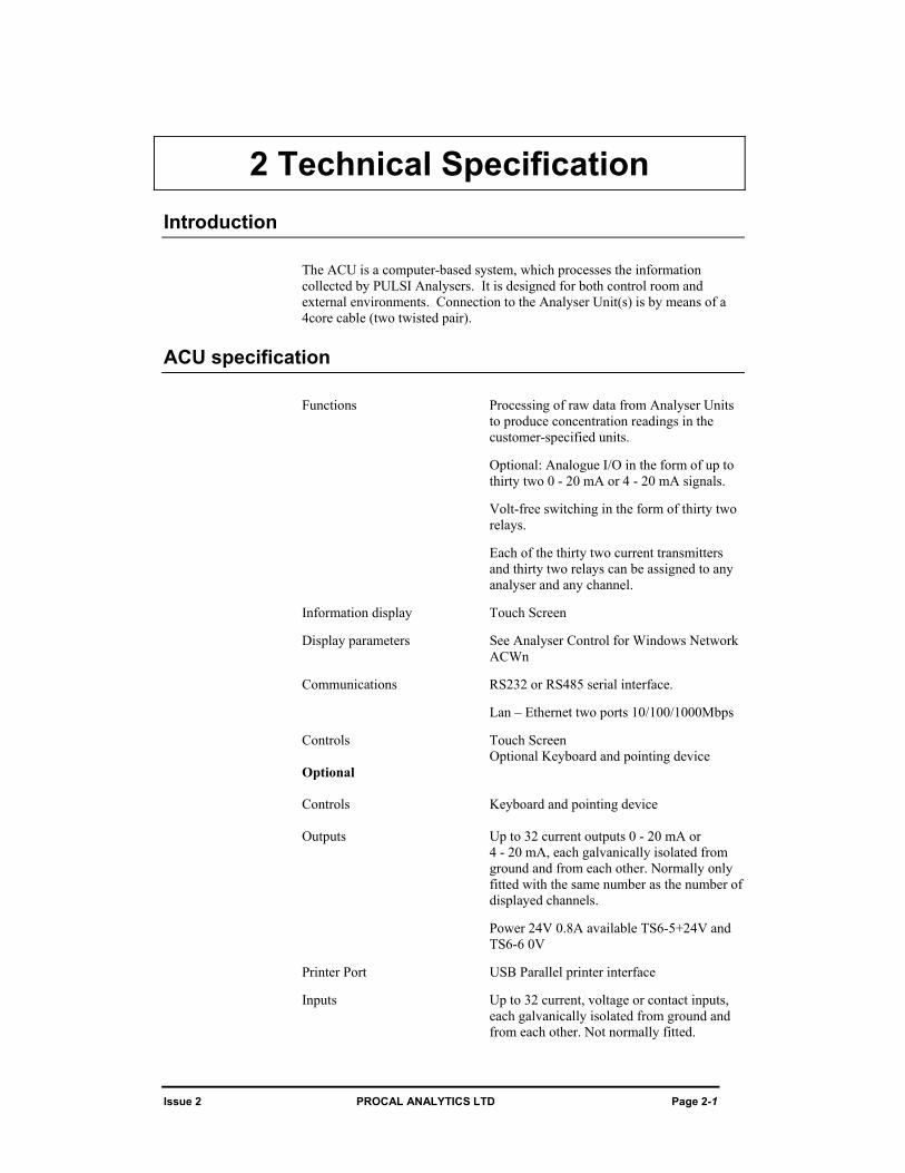
The ACU is a computer-based system, which processes the information collected by PULSI Analysers. It is designed for both control room and external environments. Connection to the Analyser Unit(s) is by means of a 4core cable (two twisted pair).
ACU specification
Functions Processing of raw data from Analyser Units to produce concentration readings in the customer-specified units.
Optional: Analogue I/O in the form of up to thirty two 0 - 20 mA or 4 - 20 mA signals.
Volt-free switching in the form of thirty two relays.
Each of the thirty two current transmitters and thirty two relays can be assigned to any analyser and any channel.
Information display Touch Screen
Display parameters See Analyser Control for Windows Network ACWn
Communications RS232 or RS485 serial interface.
Lan – Ethernet two ports 10/100/1000Mbps
Controls Touch Screen Optional Keyboard and pointing device Optional Controls Keyboard and pointing device Outputs Up to 32 current outputs 0 - 20 mA or
4 - 20 mA, each galvanically isolated from ground and from each other. Normally only fitted with the same number as the number of displayed channels.
Power 24V 0.8A available TS6-5+24V and TS6-6 0V
Printer Port USB Parallel printer interface
Inputs Up to 32 current, voltage or contact inputs, each galvanically isolated from ground and from each other. Not normally fitted.
Analyser Control Unit Mk4 Operating Manual
Page 2-2 PROCAL ANALYTICS LTD Issue 2
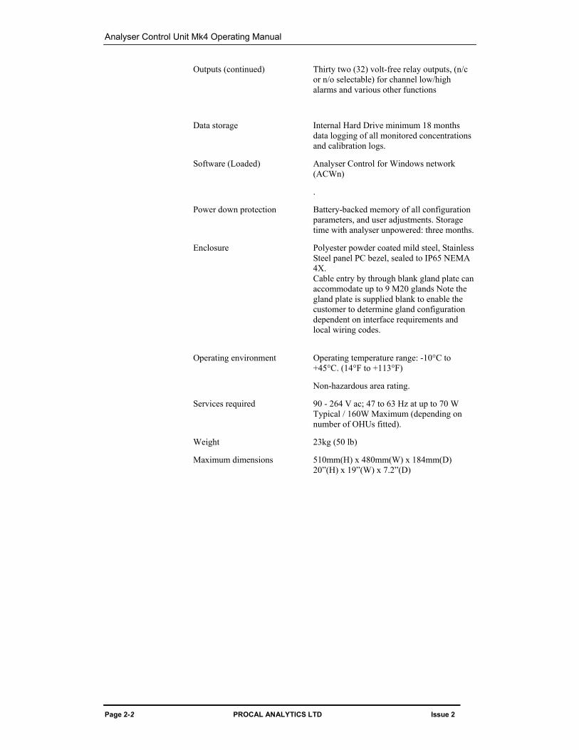
Outputs (continued) Thirty two (32) volt-free relay outputs, (n/c or n/o selectable) for channel low/high alarms and various other functions
Data storage Internal Hard Drive minimum 18 months data logging of all monitored concentrations and calibration logs.
Software (Loaded) Analyser Control for Windows network (ACWn)
.
Power down protection Battery-backed memory of all configuration parameters, and user adjustments. Storage time with analyser unpowered: three months.
Enclosure Polyester powder coated mild steel, Stainless Steel panel PC bezel, sealed to IP65 NEMA 4X. Cable entry by through blank gland plate can accommodate up to 9 M20 glands Note the gland plate is supplied blank to enable the customer to determine gland configuration dependent on interface requirements and local wiring codes.
Operating environment Operating temperature range: -10°C to +45°C. (14°F to +113°F)
Non-hazardous area rating.
Services required 90 - 264 V ac; 47 to 63 Hz at up to 70 W Typical / 160W Maximum (depending on number of OHUs fitted).
Weight 23kg (50 lb)
Maximum dimensions 510mm(H) x 480mm(W) x 184mm(D) 20”(H) x 19”(W) x 7.2”(D)
2 Technical Specification
Issue 2 PROCAL ANALYTICS LTD Page 2-3
ACU to Analyser interconnection cable lengths
Local PSU for Analyser To power each PULSI Analyser a local Power Supply Unit (PSU) is required. The nominal supply requirement for each PULSI Analyser is 24V dc at 3.5A which includes the continuous power required by the Autozero solenoid.
The PSU should be located as close to the Analyser as possible, the voltage at the analyser terminals should be not less than 22V.
Note that the P5000 analyser is mains operated.
ACU to Analyser Cable (Communication) The recommended Belden data cables have an individual screen for each twisted-pair and the drain wire for each should be connected to 0V dc at the ACU. Experience has shown that in almost all cases there is no reduction in system performance or reliability if the screen drain wire is also connected to 0V dc at each Analyser.
Unless otherwise stated, Belden 9842 data cable is assumed which has 18 AWG individual conductors the Analyser can be up to 1200M (4000’) from the ACU. Its characteristic impedance is approximately 50ohms whilst the recommended data line termination resistance for RS485 is 120ohms. Given the short cable distances used (< 300M) and the slow data rate (< 20K bits/sec) there will be no noticeable data pulse distortion. It is possible to use smaller cable such as Belden 9502 (24 AWG) where only short distances are required.

Analyser Control Unit Mk4 Operating Manual
Page 2-4 PROCAL ANALYTICS LTD Issue 2
Page left intentionally blank
Issue 2 PROCAL ANALYTICS LTD Page 3-1
3 Installation Introduction
This section describes how to install the ACU. Installation procedures for Analysers and other associated equipment are detailed in the technical manuals for those components.
WARNINGS YOU MUST NOT ATTEMPT TO INSTALL THIS SYSTEM UNLESS YOU ARE QUALIFIED, COMPETENT AND AUTHORIZED TO WORK ON ELECTRICAL EQUIPMENT OPERATING AT YOUR LOCAL MAINS ELECTRICAL SUPPLY VOLTAGE.
READ THIS SECTION IN ITS ENTIRETY BEFORE ATTEMPTING TO INSTALL ANY PART OF THE SYSTEM. IF THERE IS ANYTHING YOU DO NOT UNDERSTAND, OR YOU DO NOT FEEL CONFIDENT OF YOUR ABILITY TO FOLLOW THE INSTALLATION INSTRUCTIONS, DO NOT PROCEED. CONTACT PROCAL ANALYTICS OR YOUR PROCAL-AUTHORISED DISTRIBUTOR.
Unpacking the system components
If this has not already been done, unpack the system components and check that they correspond to the units ordered and listed on the accompanying packing note. If there is any discrepancy, or any damage is apparent, do not attempt to install the system. Contact Procal Analytics, or your Procal distributor.
Fitting and preparing the ACU
The ACU is designed to be wall mounted in the control room, shelter or other designated location. The wall mounting bracket is supplied with the ACU.
WARNING DO NOT CONNECT THE MAINS CABLE (POWER CORD) TO THE ELECTRICAL SUPPLY UNTIL ALL CONNECTIONS WITHIN THE ACU HAVE BEEN MADE. FAILURE TO FOLLOW THIS WARNING MAY RESULT IN SERIOUS OR FATAL INJURY FROM ELECTRIC SHOCK.
Gaining internal access to the ACU
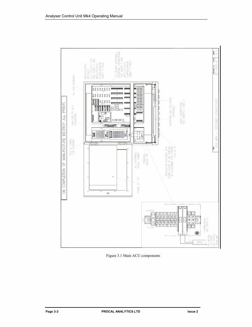
Unlock both the main hinged door and keyboard / pointing device access hinged door using the key provided. A view of the terminals and main components is shown in Figure 3-1
Analyser Control Unit Mk4 Operating Manual
Page 3-2 PROCAL ANALYTICS LTD Issue 2
Figure 3.1 Main ACU components
3 Installation
Issue 2 PROCAL ANALYTICS LTD Page 3-3
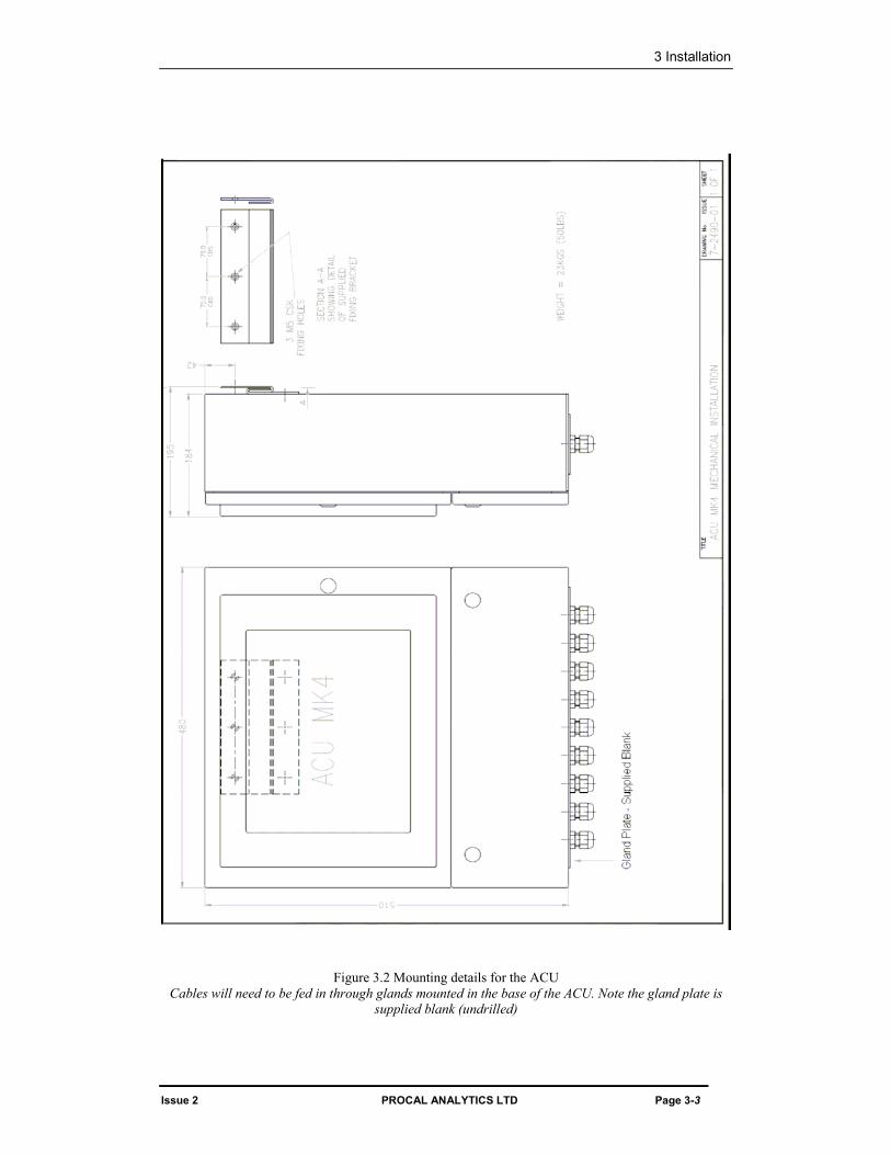
Figure 3.2 Mounting details for the ACU Cables will need to be fed in through glands mounted in the base of the ACU. Note the gland plate is
supplied blank (undrilled)
Analyser Control Unit Mk4 Operating Manual
Page 3-4 PROCAL ANALYTICS LTD Issue 2
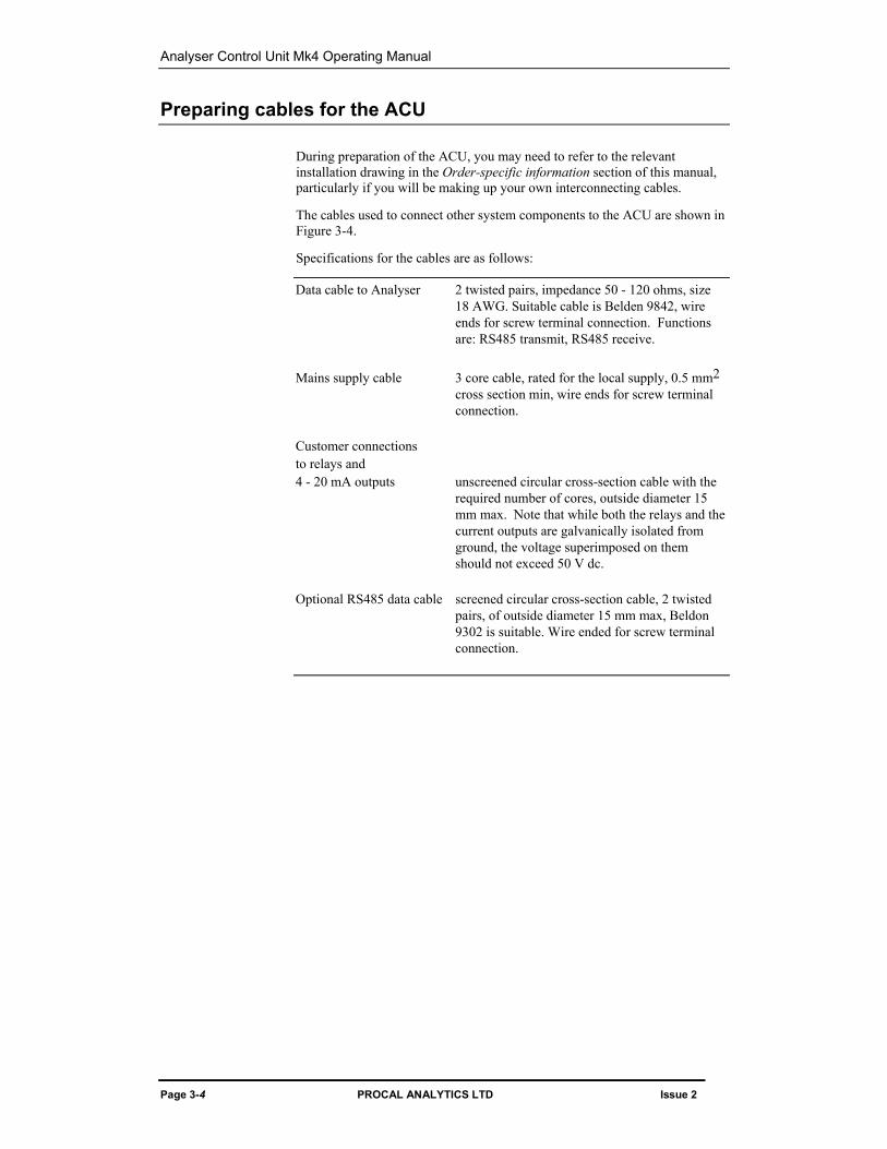
Preparing cables for the ACU
During preparation of the ACU, you may need to refer to the relevant installation drawing in the Order-specific information section of this manual, particularly if you will be making up your own interconnecting cables.
The cables used to connect other system components to the ACU are shown in Figure 3-4.
Specifications for the cables are as follows:
Data cable to Analyser 2 twisted pairs, impedance 50 - 120 ohms, size 18 AWG. Suitable cable is Belden 9842, wire ends for screw terminal connection. Functions are: RS485 transmit, RS485 receive.
Mains supply cable 3 core cable, rated for the local supply, 0.5 mm2
cross section min, wire ends for screw terminal connection.
Customer connections to relays and 4 - 20 mA outputs unscreened circular cross-section cable with the
required number of cores, outside diameter 15 mm max. Note that while both the relays and the current outputs are galvanically isolated from ground, the voltage superimposed on them should not exceed 50 V dc.
Optional RS485 data cable screened circular cross-section cable, 2 twisted
pairs, of outside diameter 15 mm max, Beldon 9302 is suitable. Wire ended for screw terminal connection.
3 Installation
Issue 2 PROCAL ANALYTICS LTD Page 3-5
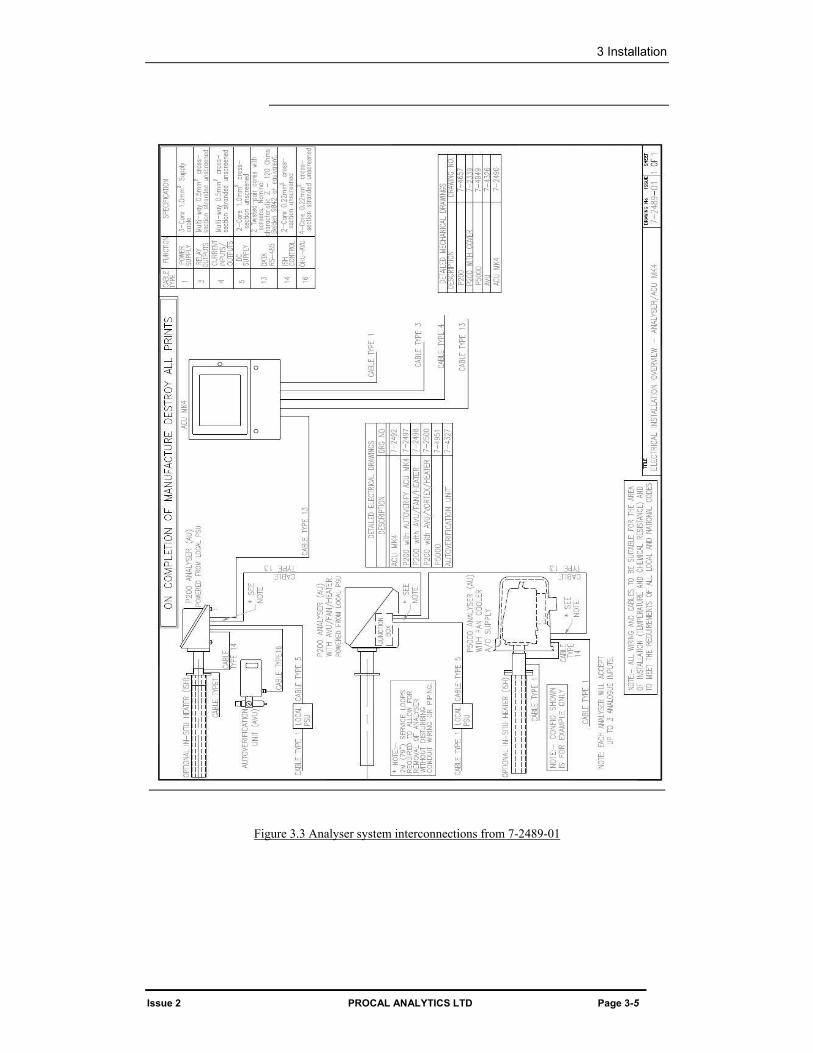
Figure 3.3 Analyser system interconnections from 7-2489-01
Analyser Control Unit Mk4 Operating Manual
Page 3-6 PROCAL ANALYTICS LTD Issue 2
Feeding cables into the ACU The gland plate mounted in the bottom of the ACU enclosure must be removed before gland holes are drilled, Before drilling it is important to determine the number of glands required. The gland for the power cable / lead should be located on the left hand side of the gland plate to line up with terminal block 1.
■
Connect the cables to the ACU as follows:
Data cable (ACU – Analyser) See 7-2492 Analyser to ACU Convertor Mains supply cable Wire to Terminal Block TB1. Connections to relay Connect to terminal TS2, TS4, TS8 or TS10 as
shown in Figure 3.5. 4 - 20 mA outputs or inputs. Connect to
terminal TS1, TS3, TS7 or TS9 as shown in Figure 3.5.
Printer Connected to the USB connector on the base of the panel PC.
Network Connected to the Network connection connector on the base of the panel PC.
External Comms (ACU – DCS) See 7-2492 External RS485 Comms Convertor
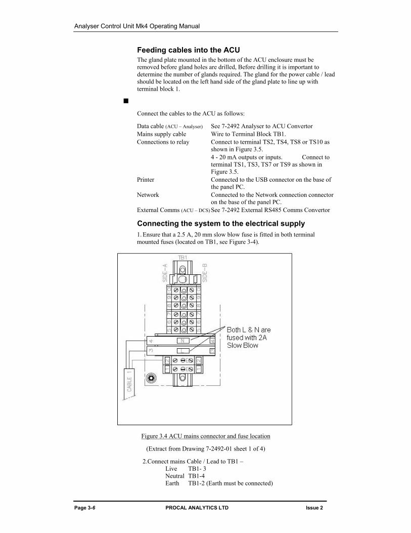
Connecting the system to the electrical supply 1. Ensure that a 2.5 A, 20 mm slow blow fuse is fitted in both terminal
mounted fuses (located on TB1, see Figure 3-4).
Figure 3.4 ACU mains connector and fuse location
(Extract from Drawing 7-2492-01 sheet 1 of 4)
2.Connect mains Cable / Lead to TB1 – Live TB1- 3 Neutral TB1-4 Earth TB1-2 (Earth must be connected)
3 Installation
Issue 2 PROCAL ANALYTICS LTD Page 3-7
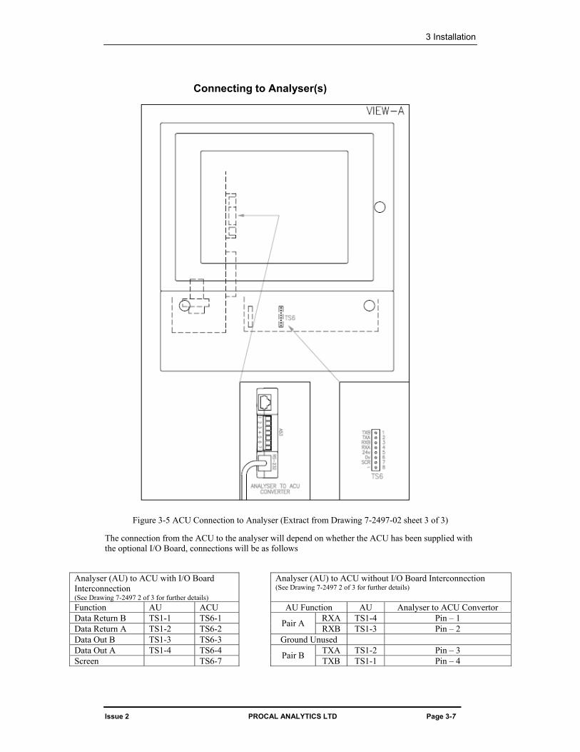
Connecting to Analyser(s)
Figure 3-5 ACU Connection to Analyser (Extract from Drawing 7-2497-02 sheet 3 of 3)
The connection from the ACU to the analyser will depend on whether the ACU has been supplied with the optional I/O Board, connections will be as follows
Analyser (AU) to ACU with I/O Board Interconnection (See Drawing 7-2497 2 of 3 for further details)
Analyser (AU) to ACU without I/O Board Interconnection (See Drawing 7-2497 2 of 3 for further details)
Function AU ACU AU Function AU Analyser to ACU Convertor Data Return B TS1-1 TS6-1 RXA TS1-4 Pin – 1 Data Return A TS1-2 TS6-2 Pair A RXB TS1-3 Pin – 2 Data Out B TS1-3 TS6-3 Ground Unused Data Out A TS1-4 TS6-4 TXA TS1-2 Pin – 3 Screen TS6-7 Pair B TXB TS1-1 Pin – 4
Analyser Control Unit Mk4 Operating Manual
Page 3-8 PROCAL ANALYTICS LTD Issue 2
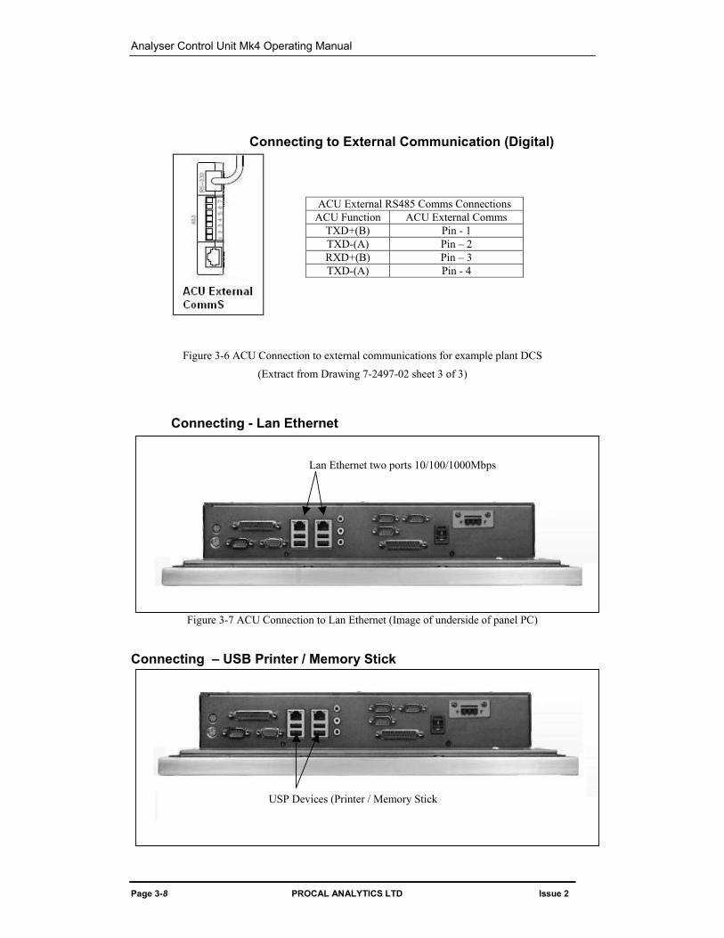
Lan Ethernet two ports 10/100/1000Mbps
USP Devices (Printer / Memory Stick
Connecting to External Communication (Digital)
Figure 3-6 ACU Connection to external communications for example plant DCS
(Extract from Drawing 7-2497-02 sheet 3 of 3)
Connecting - Lan Ethernet
Figure 3-7 ACU Connection to Lan Ethernet (Image of underside of panel PC)
Connecting – USB Printer / Memory Stick
ACU External RS485 Comms Connections ACU Function ACU External Comms
TXD+(B) Pin - 1 TXD-(A) Pin – 2 RXD+(B) Pin – 3 TXD-(A) Pin - 4
3 Installation
Issue 2 PROCAL ANALYTICS LTD Page 3-9
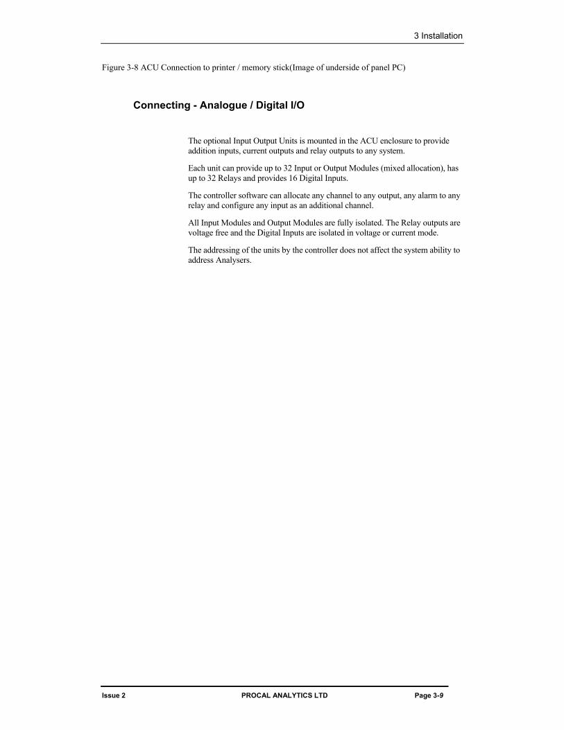
Figure 3-8 ACU Connection to printer / memory stick(Image of underside of panel PC)
Connecting - Analogue / Digital I/O
The optional Input Output Units is mounted in the ACU enclosure to provide addition inputs, current outputs and relay outputs to any system.
Each unit can provide up to 32 Input or Output Modules (mixed allocation), has up to 32 Relays and provides 16 Digital Inputs.
The controller software can allocate any channel to any output, any alarm to any relay and configure any input as an additional channel.
All Input Modules and Output Modules are fully isolated. The Relay outputs are voltage free and the Digital Inputs are isolated in voltage or current mode.
The addressing of the units by the controller does not affect the system ability to address Analysers.
Analyser Control Unit Mk4 Operating Manual
Page 3-10 PROCAL ANALYTICS LTD Issue 2
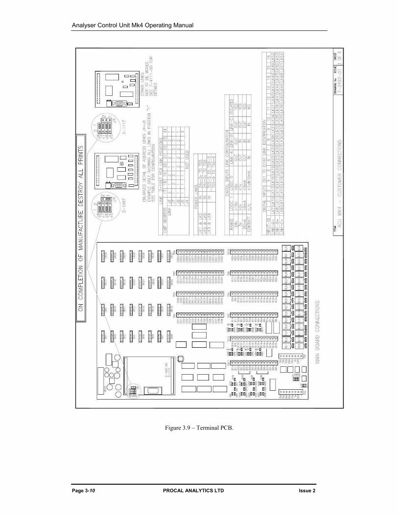
Figure 3.9 – Terminal PCB.
3 Installation
Issue 2 PROCAL ANALYTICS LTD Page 3-11
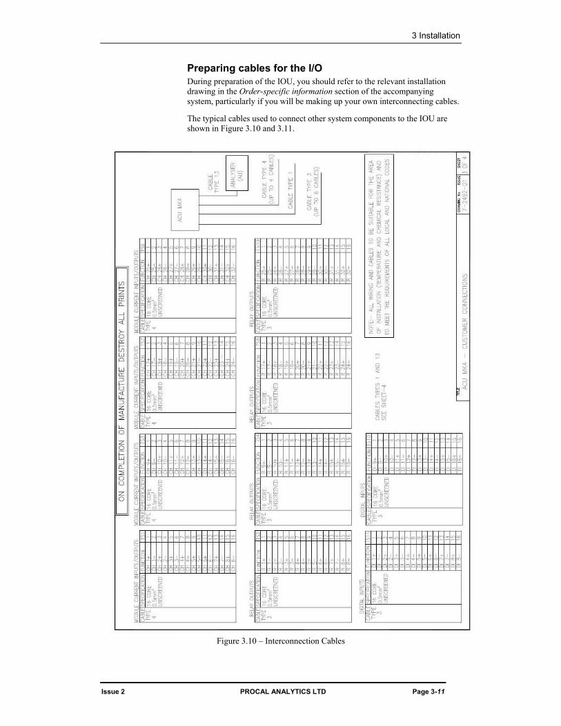
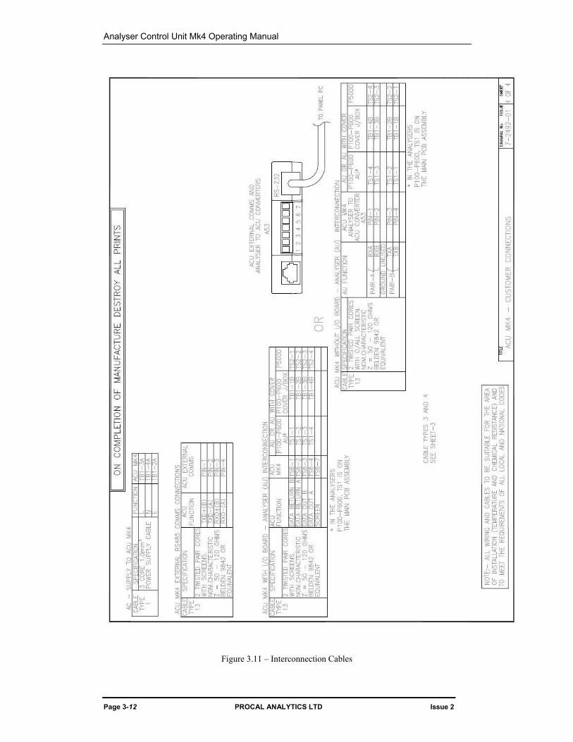
Preparing cables for the I/O During preparation of the IOU, you should refer to the relevant installation drawing in the Order-specific information section of the accompanying system, particularly if you will be making up your own interconnecting cables.
The typical cables used to connect other system components to the IOU are shown in Figure 3.10 and 3.11.
Figure 3.10 – Interconnection Cables
Analyser Control Unit Mk4 Operating Manual
Page 3-12 PROCAL ANALYTICS LTD Issue 2
Figure 3.11 – Interconnection Cables
3 Installation
Issue 2 PROCAL ANALYTICS LTD Page 3-13
System configuration The System Database provided will be configured to suit the Inputs and Outputs configurations ordered. If changes need to be made consult the relevant section in the ACWn Controller Manual.
Module configuration See IOU Configuration Sheet (7-7806) form entries for this delivery Module setup details.
See IOU Customer Connections drawing 7-4384 for Module locations, Relay Links and Digital Input Link locations.
Output Modules – No configuration required.
Input Modules – Link selection for three modes. J2 in, J1 out for 0-20mA or 4-20mA range. J2 and J1 out for 5V range. J1 and J2 in for Switch detection. Digital inputs. – Link selection for four detection modes. Links A, B, C out; 24V Logic. Link B in.; 5V or 20mA Logic. Links A, B, C in; Contact detection. Relay Outputs – Link selection for NO (Normally Open) and NC (Normally Closed) operation. When powered off the IOU relays will be in the Normal position. By default the error condition is this power off condition. Relay Rating - 28V dc max, 1A max. Not suitable for mains switching nor signal switching.
Analyser Control Unit Mk4 Operating Manual
Page 3-14 PROCAL ANALYTICS LTD Issue 2
Operation
NOTE: If the IOU is powered without communications from the Control Software then all relays will be in their alarm state and all current transmitters will output 2mA. A timeout is provided after communications is established to ensure the above occurs only in the case of a communications fault.
The Output Modules have an LED on the module which is illuminated in an Error condition. This error is the result of the Module being unable to create any current output. This will be normally be because the output for this module is open circuit. Hence these LEDs can be used to check the system wiring. Note this requires operating the IOU with the cover removed. This should only be done by a qualified service engineer and the earlier warning as to operation on Mains Voltage applies.
Connecting the system to the supply The ACU has been designed to operate on either of two power supplies:
■ 110 V ac nominal (low limit 85 V, high limit 130 V), 50-60 Hz.
■ 230 V ac nominal (low limit 190 V, high limit 264 V), 50-60 Hz.
No user adjustment is necessary as the ACU automatically detects the input voltage. The procedure to connect the system to the mains supply is:
1. Ensure that all wiring between the ACU, Analysers(s) (AU)s and ancillary equipment is correct.
2. Connect the free end of the mains cable to a suitable ac supply. Follow local regulations for permanently installed equipment. It is recommended as good practice that a means of disconnection is provided within 2 meters and an RCD or ELB is also fitted.
The installation is now complete and the system is ready for operation.
The electrical connections are detailed on drawing 7-2492.
Issue 2 PROCAL ANALYTICS LTD Page 4-1
4 Software Operation and configuring
See Analyser Control For Windows For Network operating manual 7-3038 supplied with ACU

Analyser Control Unit Mk4 Operating Manual
Page 4-2 PROCAL ANALYTICS LTD Issue 2
Page left intentionally blank