Analyse different anchorage solutions using advanced nonlinear...
31
1
Transcript of Analyse different anchorage solutions using advanced nonlinear...

1

1. Webinar Purpose
2. Introduction to midas FEA
3. Reference Material
4. Analysis Details
5. Results
6. Conclusion
7. Future Research Possibilities
2
• Analyse different anchorage solutions using advanced nonlinear numerical models
• Compare stress distribution to theoretical models
• Check crack distribution
• Compare crack distribution considering:• High Strength Concrete(C90/105) vs. UHPFRC (G2TM)
• Plain concrete vs. Reinforced concrete
3
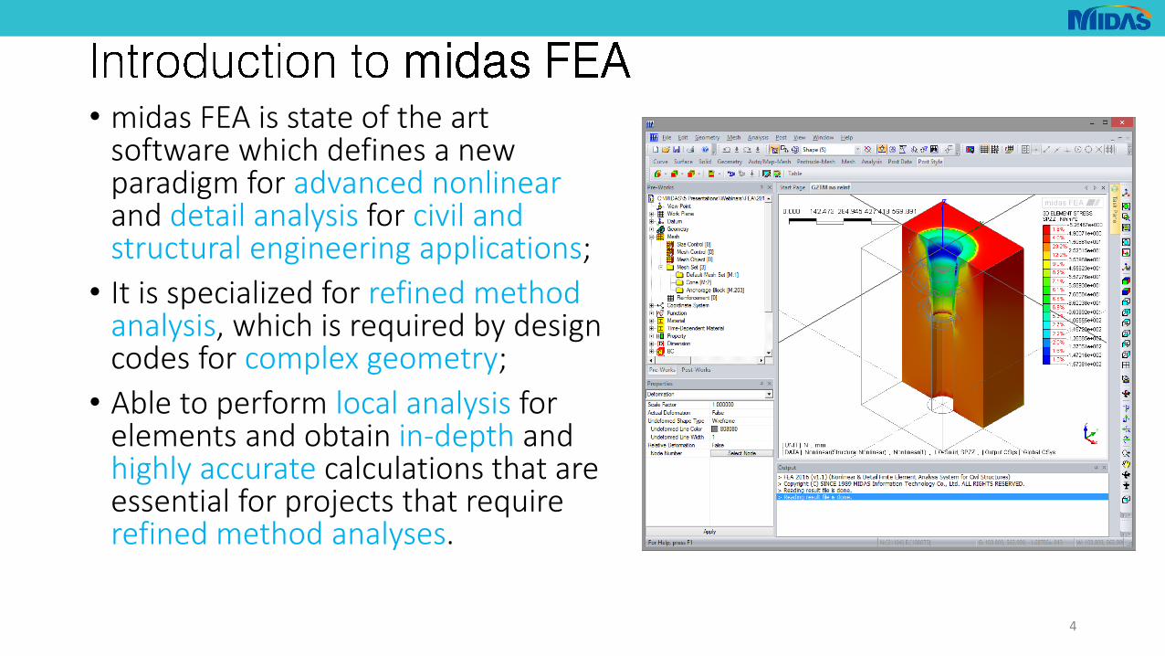
• midas FEA is state of the art software which defines a new paradigm for advanced nonlinear and detail analysis for civil and structural engineering applications;
• It is specialized for refined method analysis, which is required by design codes for complex geometry;
• Able to perform local analysis for elements and obtain in-depth and highly accurate calculations that are essential for projects that require refined method analyses.
4
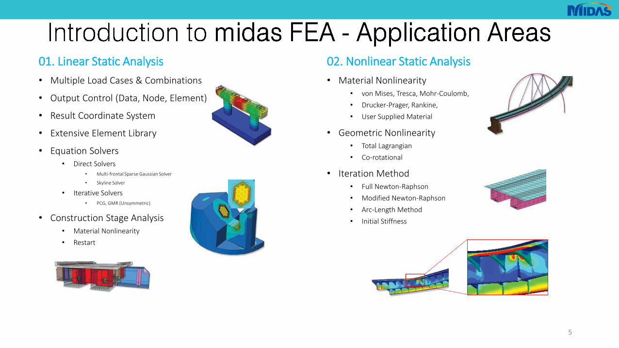
01. Linear Static Analysis
• Multiple Load Cases & Combinations
• Output Control (Data, Node, Element)
• Result Coordinate System
• Extensive Element Library
• Equation Solvers• Direct Solvers
• Multi-frontal Sparse Gaussian Solver
• Skyline Solver
• Iterative Solvers• PCG, GMR (Unsymmetric)
• Construction Stage Analysis• Material Nonlinearity
• Restart
02. Nonlinear Static Analysis
• Material Nonlinearity• von Mises, Tresca, Mohr-Coulomb,
• Drucker-Prager, Rankine,
• User Supplied Material
• Geometric Nonlinearity• Total Lagrangian
• Co-rotational
• Iteration Method• Full Newton-Raphson
• Modified Newton-Raphson
• Arc-Length Method
• Initial Stiffness
5
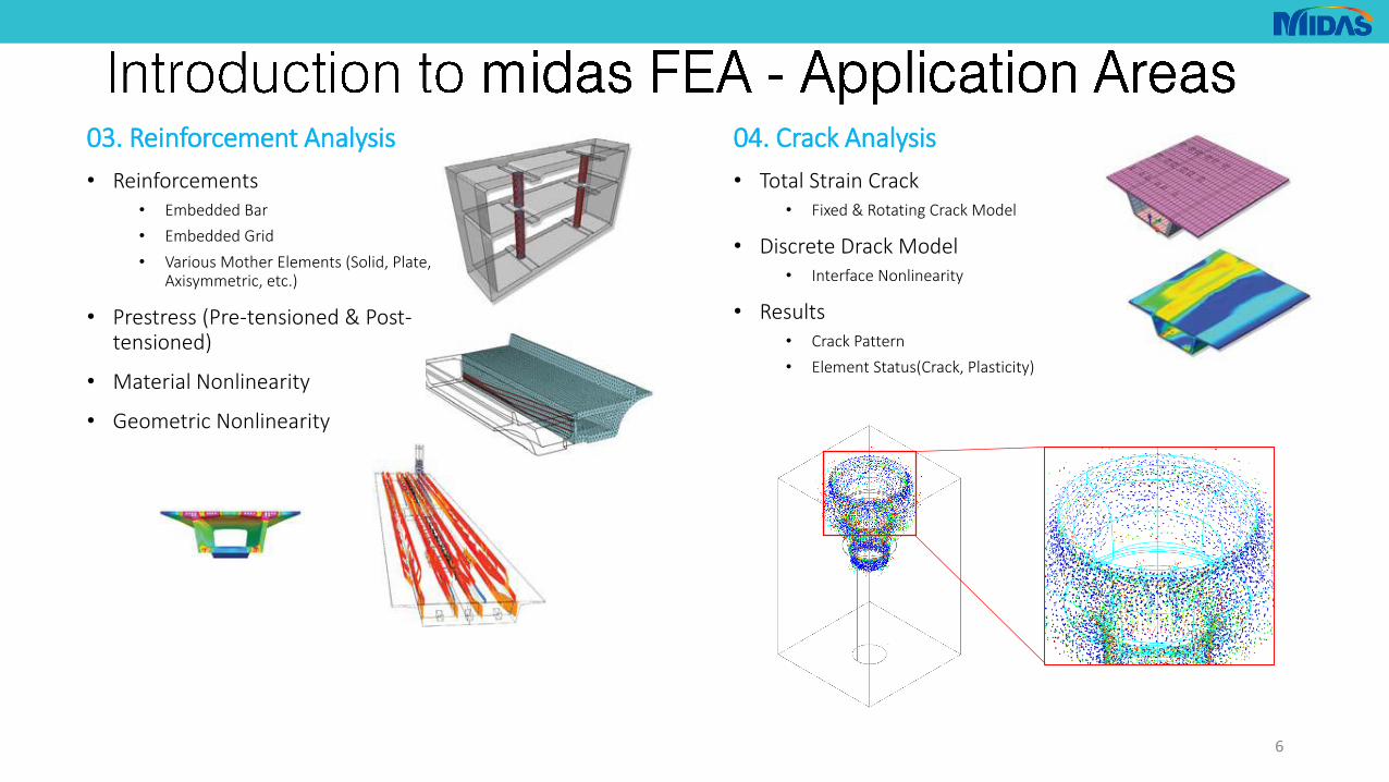
03. Reinforcement Analysis
• Reinforcements• Embedded Bar
• Embedded Grid
• Various Mother Elements (Solid, Plate, Axisymmetric, etc.)
• Prestress (Pre-tensioned & Post-tensioned)
• Material Nonlinearity
• Geometric Nonlinearity
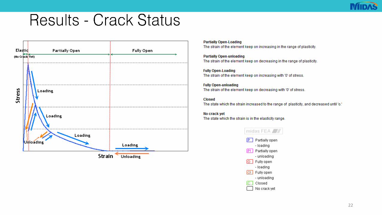
04. Crack Analysis
• Total Strain Crack• Fixed & Rotating Crack Model
• Discrete Drack Model• Interface Nonlinearity
• Results• Crack Pattern
• Element Status(Crack, Plasticity)
6
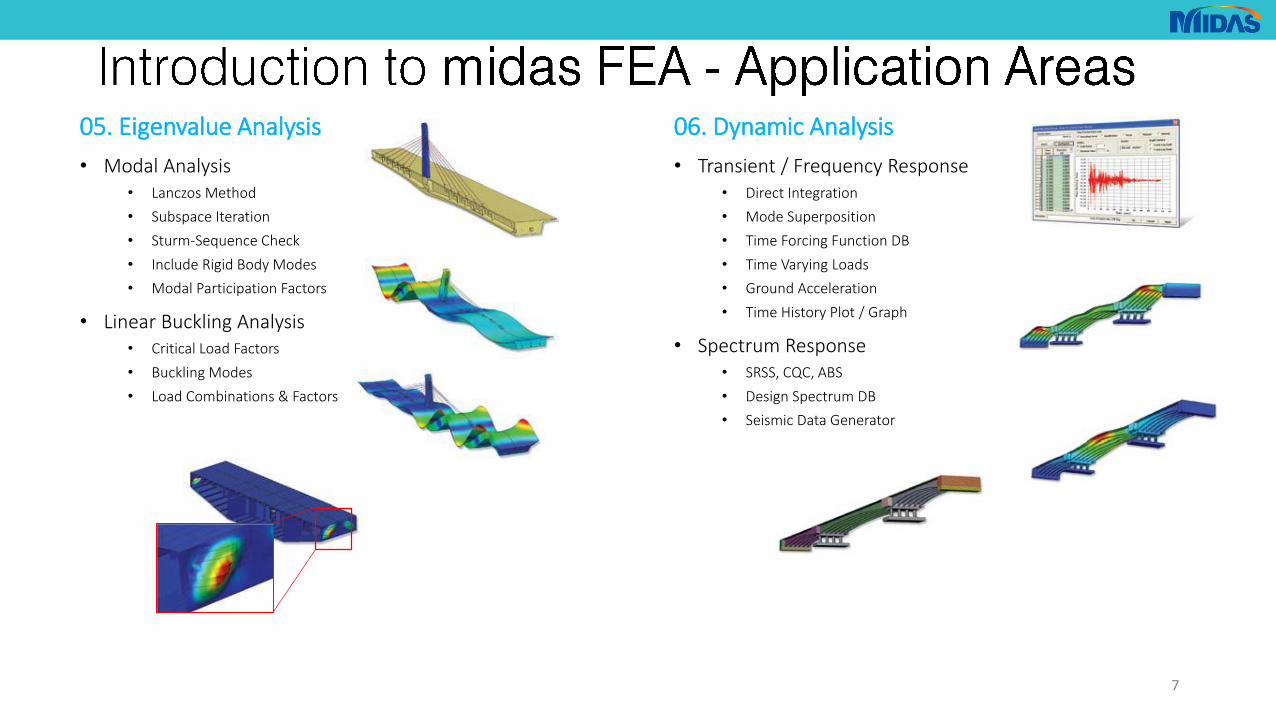
05. Eigenvalue Analysis
• Modal Analysis• Lanczos Method
• Subspace Iteration
• Sturm-Sequence Check
• Include Rigid Body Modes
• Modal Participation Factors
• Linear Buckling Analysis• Critical Load Factors
• Buckling Modes
• Load Combinations & Factors
06. Dynamic Analysis
• Transient / Frequency Response• Direct Integration
• Mode Superposition
• Time Forcing Function DB
• Time Varying Loads
• Ground Acceleration
• Time History Plot / Graph
• Spectrum Response• SRSS, CQC, ABS
• Design Spectrum DB
• Seismic Data Generator
7
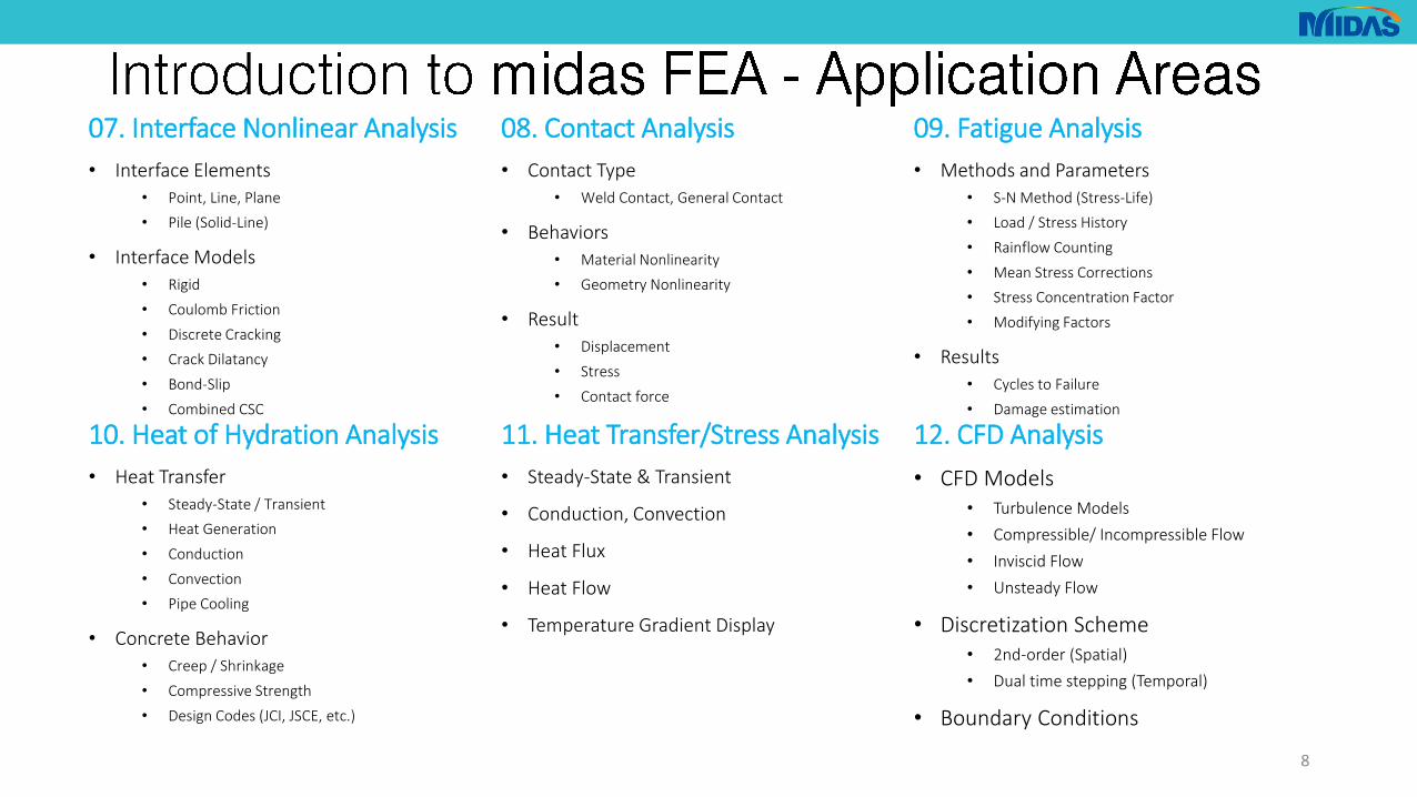
07. Interface Nonlinear Analysis
• Interface Elements
• Point, Line, Plane
• Pile (Solid-Line)
• Interface Models
• Rigid
• Coulomb Friction
• Discrete Cracking
• Crack Dilatancy
• Bond-Slip
• Combined CSC
08. Contact Analysis
• Contact Type
• Weld Contact, General Contact
• Behaviors
• Material Nonlinearity
• Geometry Nonlinearity
• Result
• Displacement
• Stress
• Contact force
09. Fatigue Analysis
• Methods and Parameters
• S-N Method (Stress-Life)
• Load / Stress History
• Rainflow Counting
• Mean Stress Corrections
• Stress Concentration Factor
• Modifying Factors
• Results
• Cycles to Failure
• Damage estimation
10. Heat of Hydration Analysis
• Heat Transfer
• Steady-State / Transient
• Heat Generation
• Conduction
• Convection
• Pipe Cooling
• Concrete Behavior
• Creep / Shrinkage
• Compressive Strength
• Design Codes (JCI, JSCE, etc.)
11. Heat Transfer/Stress Analysis
• Steady-State & Transient
• Conduction, Convection
• Heat Flux
• Heat Flow
• Temperature Gradient Display
12. CFD Analysis
• CFD Models• Turbulence Models
• Compressible/ Incompressible Flow
• Inviscid Flow
• Unsteady Flow
• Discretization Scheme• 2nd-order (Spatial)
• Dual time stepping (Temporal)
• Boundary Conditions
8
• EUROCODE 2
• CIRIA: A guide to the design of anchor blocks for post-tensioned concrete members
• Structural Implications of Ultra-High Performance Fibre-Reinforced Concrete in Bridge Design, Ana Spasojević (2008)
• Ultra High Performance Fibre-Reinforced Concretes: Interim Recommendations, AFGC-SETRA (2002)
• Testing and analysing innovative design of UHPFRC anchor blocks for post-tensioning tendons, F. Toutlemonde, J.-C. Renaud & L. Lauvin
9

Geometry
10
Material Properties
• S355
• Plastic material constitutive model: von Mises

11
Geometry Material Properties
• Two separate cases:• High Strength Concrete: C90/105
• Ultra High Performance Fiber Reinforced Concrete: Ductal G2TM
• In both cases the Total Strain Crack constitutive model will be used
• For each type of concrete two cases will be considered:• Plain concrete
• Reinforced (only bursting reinforcement modelled)

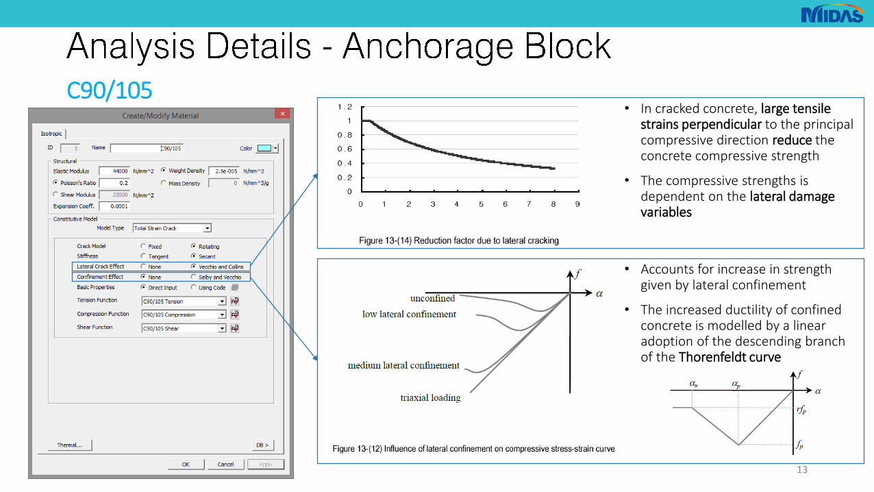
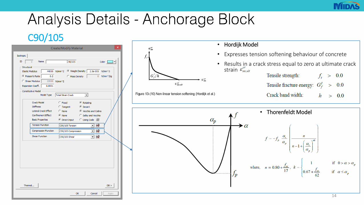
C90/105
12
• Smeared crack model
• Fixed crack model: the axes of cracks remain unchanged once the crack axes are defined
• Rotating crack model: the directions of the cracks are assumed to continuously rotate depending on the changes in the axes of principle strains
• Secant stiffness: suitable for finding excellent and stable solutions to analyses of reinforced concrete structures, which widely develop cracks
• Tangent stiffness: very appropriate for analyses of local cracking or crack propagation
C90/105
13
• In cracked concrete, large tensilestrains perpendicular to the principal compressive direction reduce the concrete compressive strength
• The compressive strengths is dependent on the lateral damage variables
• Accounts for increase in strength given by lateral confinement
• The increased ductility of confined concrete is modelled by a linear adoption of the descending branch of the Thorenfeldt curve
C90/105
14
• Hordijk Model
• Expresses tension softening behaviour of concrete
• Results in a crack stress equal to zero at ultimate crack strain
• Thorenfeldt Model

Mechanical characteristics at 28 days
Characteristic compressive strength f_ck 150.00 MPa
Characteristic limit of elasticity under tension f_ctk,el 8.00 MPa
Characteristic maximal post-cracking stress f_ctfk = σ_(0,3) 6.10 MPa
Mean Young’s modulus E_cm 53000.00 MPa
Poisson’s ratio 0.20
Other characteristics
Density 24 to 25 kN/m^3
Thermal expansion coefficient at 28 days 11.00 μm/m/°C
Autogenous shrinkage from 0 to 90 days ≤0.5 mm/m
Drying shrinkage from 0 to 90 days ≤0.3 mm/m
Creep coefficient 1.00
Durability characteristics
Water porosity at 90 days 1.5 to 2.5 %
Oxygen permeability at 28 days (at 20°C) ≤6*10^(-19) m^2
Chloride ions diffusion coefficient ≤0.5*10^(-12) m^2*s^(-1)
Mercury porosity at 90 jours 3 to 5 %
Carbonation thickness (natural and accelerated conditions) ≤0.1 mm
Resistance to freeze / thaw cycles (severe conditions – 300 cycles) 100.00 %
Resistance to spalling (de-icing salts - 56 cycles) ≤10 g/m^2
Resistance to hydraulic abrasion (CNR coefficient) 1.00
Impact resistance (CNR print testing) 65.00
15
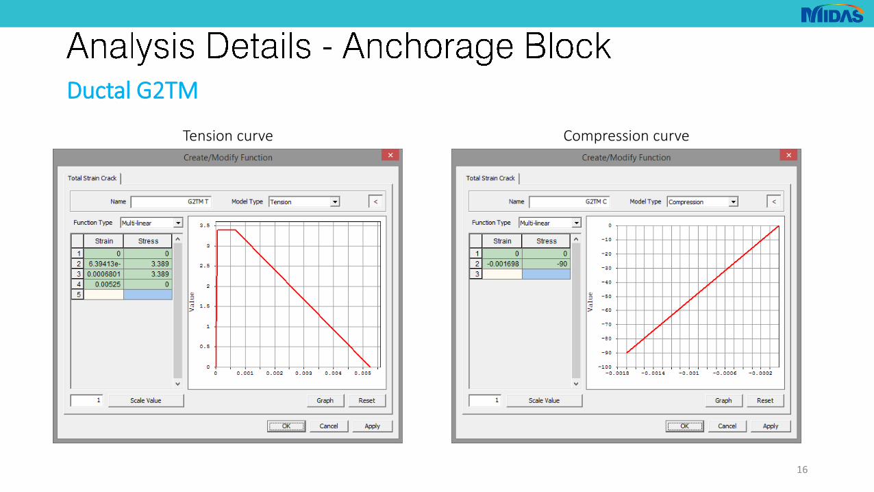
Ductal G2TM
Compression curve Tension curve
StrainStress [MPa]
StrainStress [MPa]
0 0 0 0
f_cd -0.00169811 -90 f_ctfk/K 6.39E-05 3.388889
ε_u,pic 6.80E-04 3.388889
K_local 1.8 ε_lim 5.25E-03 0
Ductal G2TM
16
Tension curve Compression curve

B500C
• Two reinforcement spirals• Spiral 1 Diameter: 200mm
• Spiral 2 Diameter: 250mm
• Bar diameter: 10mm
• As per CIRIA:• Spiral diameter ≥ anchorage(2ypo)+50mm
• Distributed in region [0.2yo, 2yo]
17
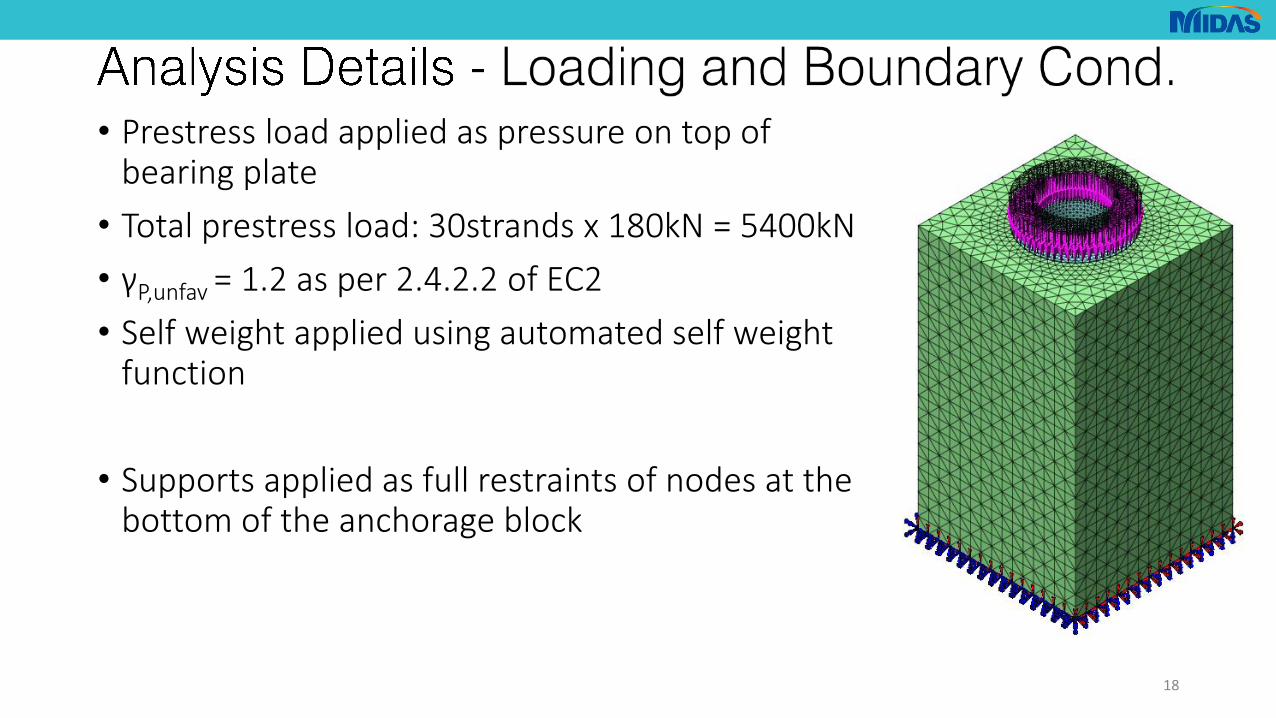
• Prestress load applied as pressure on top of bearing plate
• Total prestress load: 30strands x 180kN = 5400kN
• γP,unfav = 1.2 as per 2.4.2.2 of EC2
• Self weight applied using automated self weight function
• Supports applied as full restraints of nodes at the bottom of the anchorage block
18
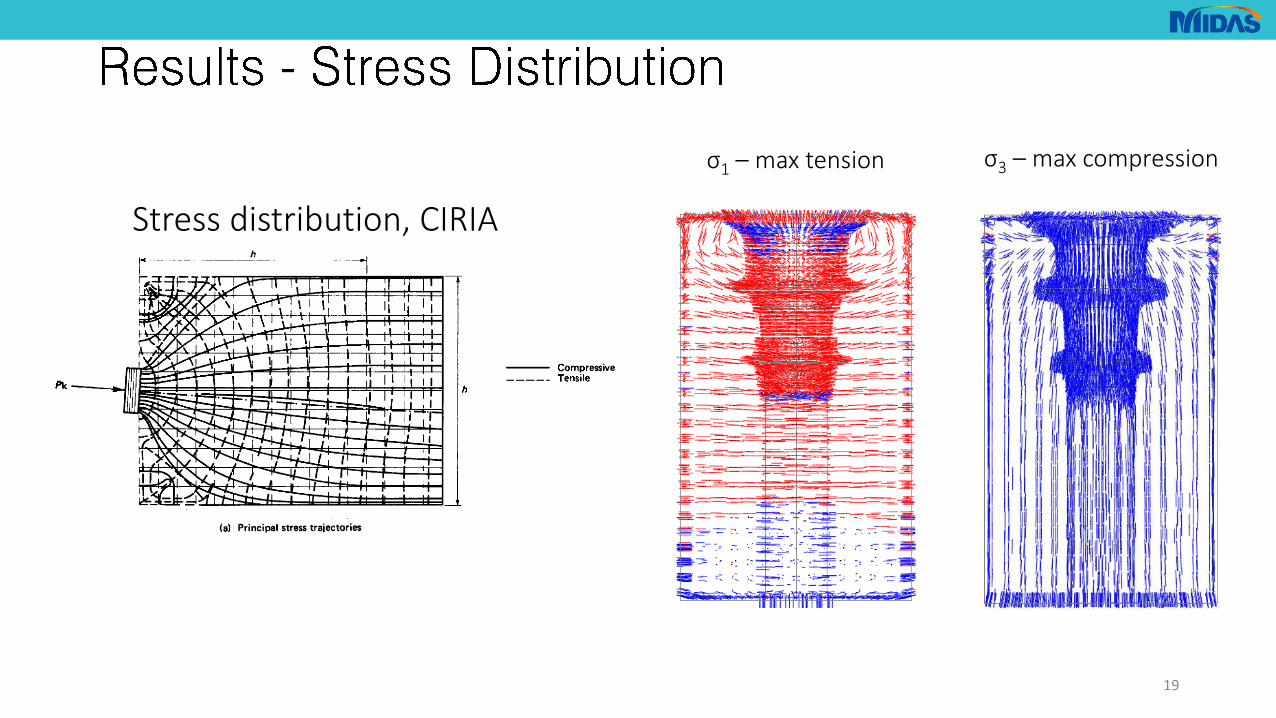
Stress distribution, CIRIA
19
σ1 – max tension σ3 – max compression

σ1
C90/105 no reinforcement
20
C90/105 with reinforcement
UHPFRC no reinforcement UHPFRC with reinforcement
0.85Pt

σ3
C90/105 no reinforcement
21
C90/105 with reinforcement
UHPFRC no reinforcement UHPFRC with reinforcement
0.85Pt
22
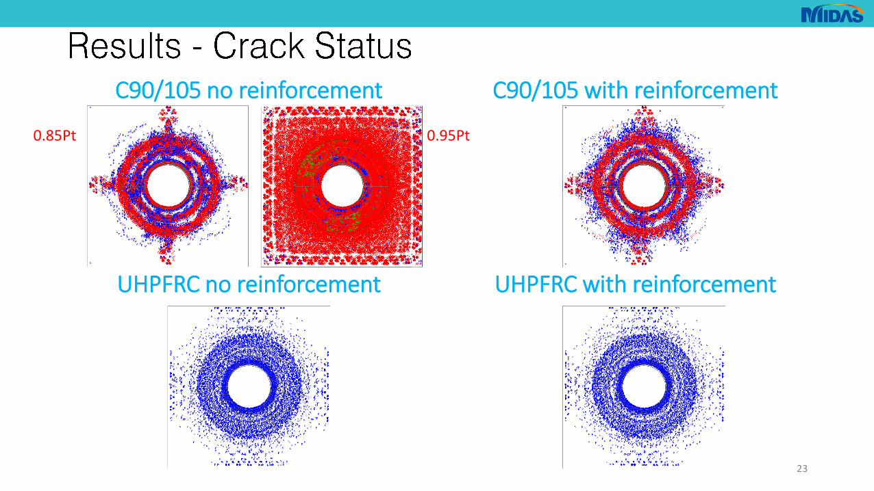
C90/105 no reinforcement
23
C90/105 with reinforcement
UHPFRC no reinforcement UHPFRC with reinforcement
0.85Pt 0.95Pt

C90/105 no reinforcement
24
C90/105 with reinforcement
UHPFRC no reinforcement UHPFRC with reinforcement
0.85Pt 0.95Pt
25
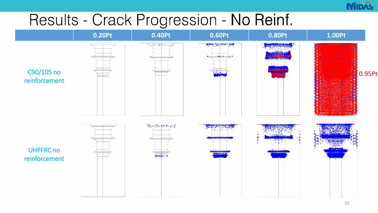
0.20Pt 0.40Pt 0.60Pt 0.80Pt 1.00Pt
C90/105 no reinforcement
UHPFRC no reinforcement
0.95Pt

26
0.20Pt 0.40Pt 0.60Pt 0.80Pt 1.00Pt
C90/105 with reinforcement
UHPFRC with reinforcement
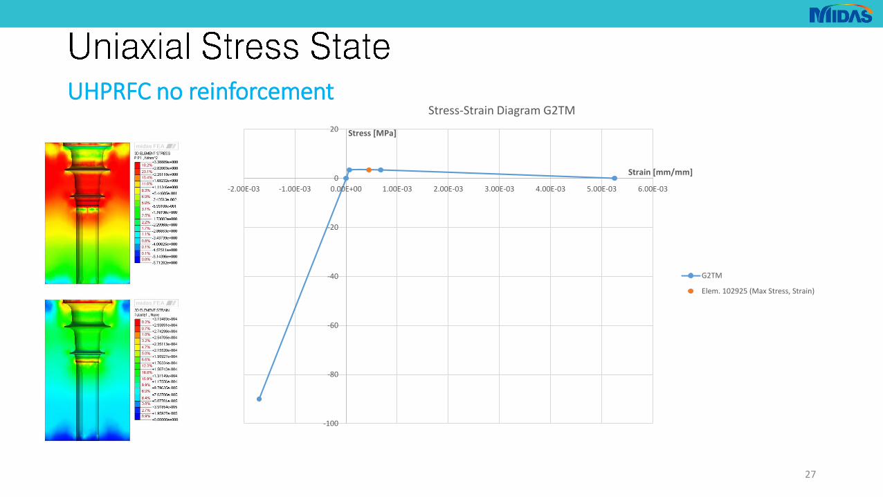
UHPRFC no reinforcement
27
-100
-80
-60
-40
-20
0
20
-2.00E-03 -1.00E-03 0.00E+00 1.00E-03 2.00E-03 3.00E-03 4.00E-03 5.00E-03 6.00E-03
Stress [MPa]
Strain [mm/mm]
Stress-Strain Diagram G2TM
G2TM
Elem. 102925 (Max Stress, Strain)
28
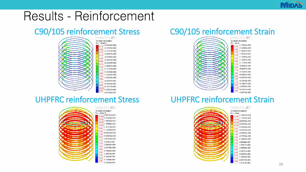
C90/105 reinforcement Stress C90/105 reinforcement Strain
UHPFRC reinforcement Stress UHPFRC reinforcement Strain
• Bursting reinforcement has a very beneficial effect for HSC
• The reinforcement has little to no effect on the crack distribution for UHPFRC
• UHPFRC shows a more even distribution of stresses compared to HSC
• The fibers have a very beneficial effect on crack distribution, helping to keep the crack dimensions limited
29
• Check theoretical models against tests on UHPFRC samples
• Improve calibration of models from tests on UHPFRC samples
• Implement UHPFRC models and databases as standard for finite element software
• Better implementation of UHPFRC into current design standards, as current codes tend to be ultra conservative
30

Contact us at:
+44 (0)207 559 1389
Visit our website at:
uk.midasuser.com
31
![midas DShop Auto-drafting Module for midas Gen 01 02admin.midasuser.com/UploadFiles2/84/Dshop_catalog.pdf · Auto-drafting Module for midas Gen [midas Gen Design Results] [midas DShop](https://static.fdocuments.in/doc/165x107/5ade06cd7f8b9a9a768db6e7/midas-dshop-auto-drafting-module-for-midas-gen-01-module-for-midas-gen-midas-gen.jpg)