Analogue and a Digital control systems -...
22
Analogue and a Digital control systems Lecturer: Owen Funnell Unit 24 - Controlling Systems Using IT P2 - Explain the characteristics of digital and analogue control systems M1 - Compare analogue and digital signals M2 - Explain the need for signal conversion
Transcript of Analogue and a Digital control systems -...

Analogue and a Digital control systems
Lecturer: Owen Funnell Unit 24 - Controlling Systems Using IT
P2 - Explain the characteristics of digital and analogue control systems
M1 - Compare analogue and digital signals
M2 - Explain the need for signal conversion

Lecturer: Owen Funnell Unit 24 - Controlling Systems Using IT
Signals are passed between devices in order to
send and receive information, which might be
video, audio, or some sort of encoded data.
Usually the signals are transmitted through
wires, but they could also pass through the air via radio frequency (RF) waves.
Signals in Control Systems

Lecturer: Owen Funnell Unit 24 - Controlling Systems Using IT
Signals in Control Systems
Digital signals are a series of pulses consisting of just two
states: ON (1) or OFF (0). There are no values in between.
DAB radio is Digital Audio Broadcast radio - it is transmitted as
digital signals. high, also known as 1 or 'on'
low, also known as 0 or ‘off’
Lecturer: Owen Funnell Unit 24 - Controlling Systems Using IT
Signals in Control Systems
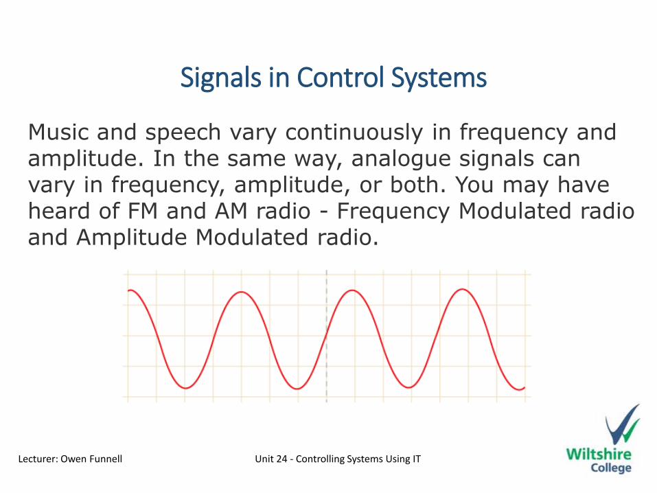
Music and speech vary continuously in frequency and amplitude. In the same way, analogue signals can vary in frequency, amplitude, or both. You may have heard of FM and AM radio - Frequency Modulated radio and Amplitude Modulated radio.
P2 - Explain the characteristics of digital and analogue control systems
Lecturer: Owen Funnell Unit 24 - Controlling Systems Using IT
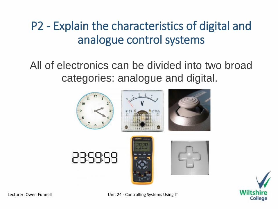
All of electronics can be divided into two broad categories: analogue and digital.

Lecturer: Owen Funnell Unit 24 - Controlling Systems Using IT
P2 - Explain the characteristics of digital and analogue control systems
The inputs that make upAnalogue Control Systems
Analogue inputs vary over a range, for example a temperature sensor can measure minus to plus temperatures. A volume control goes from low
(Silent) to high (Loud). An analogue stick on a gamepad starts a position zero ( 0X and 0Y) and can move in various direction (X and Y axis)
Lecturer: Owen Funnell Unit 24 - Controlling Systems Using IT
P2 - Explain the characteristics of digital and analogue control systems
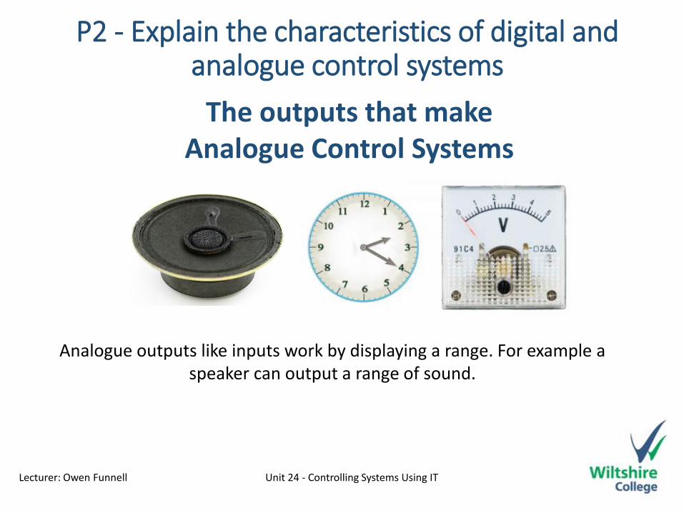
The outputs that makeAnalogue Control Systems
Analogue outputs like inputs work by displaying a range. For example a speaker can output a range of sound.

Lecturer: Owen Funnell Unit 24 - Controlling Systems Using IT
P2 - Explain the characteristics of digital and analogue control systems
The processing used in theAnalogue Control Systems
Analogue signals must be processed by an analogue-to-digital converter (ADC) before they can be processed by a logic gate.
Lecturer: Owen Funnell Unit 24 - Controlling Systems Using IT
P2 - Explain the characteristics of digital and analogue control systems
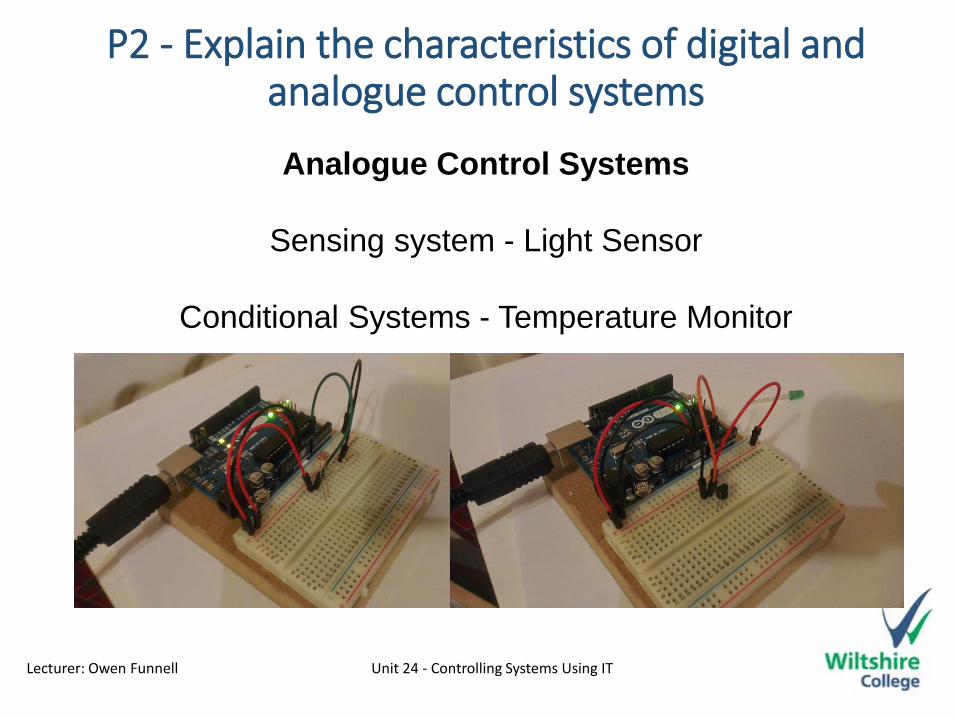
Analogue Control Systems
Sensing system - Light Sensor
Conditional Systems - Temperature Monitor
Lecturer: Owen Funnell Unit 24 - Controlling Systems Using IT
P2 - Explain the characteristics of digital and analogue control systems
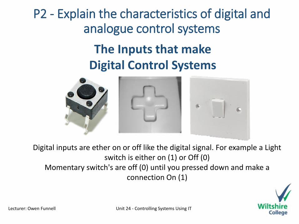
The Inputs that makeDigital Control Systems
Digital inputs are ether on or off like the digital signal. For example a Light switch is either on (1) or Off (0)
Momentary switch's are off (0) until you pressed down and make a connection On (1)

Lecturer: Owen Funnell Unit 24 - Controlling Systems Using IT
P2 - Explain the characteristics of digital and analogue control systems
The outputs that makeDigital Control Systems
Again Digital outputs are either On (1) or Off (0) LEDs are On or Off. LCD screens are made of pixels which are on or off. Turning certain pixels on
allows you to make words or pictures

Lecturer: Owen Funnell Unit 24 - Controlling Systems Using IT
P2 - Explain the characteristics of digital and analogue control systems
The processing used in theDigital Control Systems
Digital signals must be processed by a logic gates.Logic gates allow an electronic system to make a decision based on a number on its inputs.

Lecturer: Owen Funnell Unit 24 - Controlling Systems Using IT
P2 - Explain the characteristics of digital and analogue control systemsAnalogue Control Systems
Command Systems - Button Blink
Programmable Systems - Decision Maker
Lecturer: Owen Funnell Unit 24 - Controlling Systems Using IT
P2 - Explain the characteristics of digital and analogue control systems
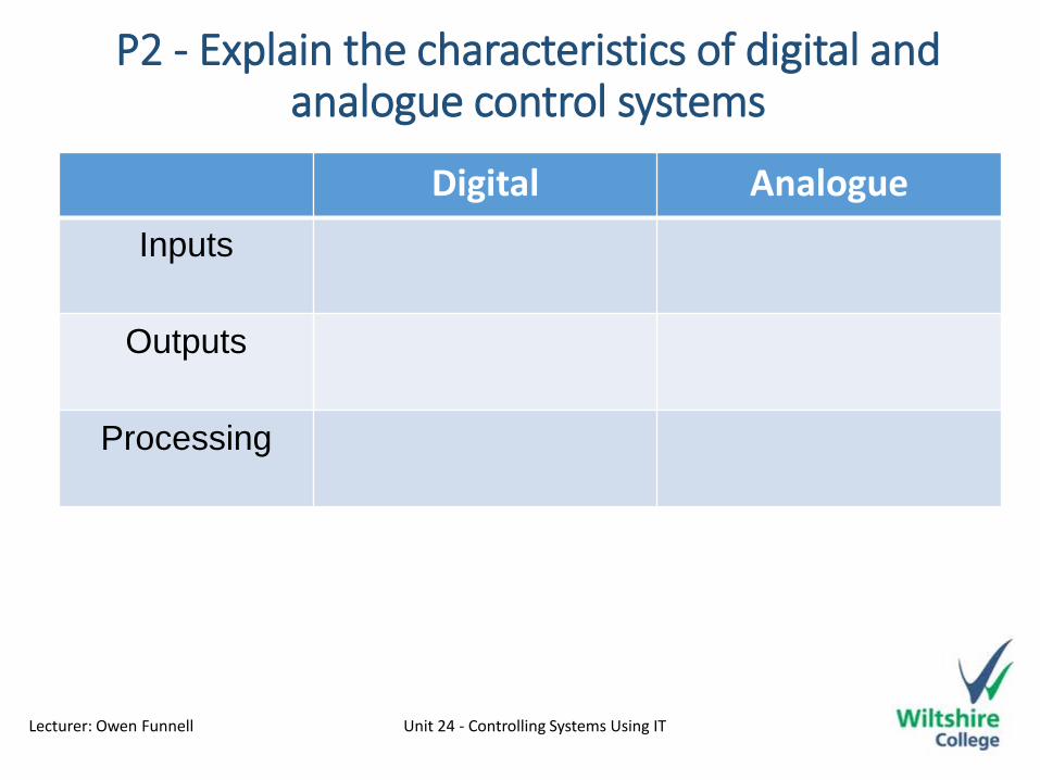
Best done in a tableDigital Analogue
Inputs
Outputs
Processing
Lecturer: Owen Funnell Unit 24 - Controlling Systems Using IT
M1 - Compare analogue and digital signals
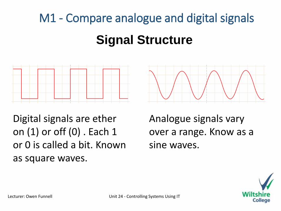
Signal Structure
Digital signals are ether on (1) or off (0) . Each 1 or 0 is called a bit. Known as square waves.
Analogue signals vary over a range. Know as a sine waves.

Lecturer: Owen Funnell Unit 24 - Controlling Systems Using IT
M1 - Compare analogue and digital signals
Response to Noise
Less affected since noise response are analogue in nature
More likely to get affected reducing accuracy
Think of your Telly vison before digital switchover

Lecturer: Owen Funnell Unit 24 - Controlling Systems Using IT
M1 - Compare analogue and digital signals
Bandwidth and Data
Digital Signals store data Stored in the form of binary bit (1 or a 0) Large Bandwidth (lots of data)
Stored in the form of wave signal. Ranging from 0 (in the middle) to 5 (High) and -5 (low) Low amount of data
This is best done in a Table
Lecturer: Owen Funnell Unit 24 - Controlling Systems Using IT
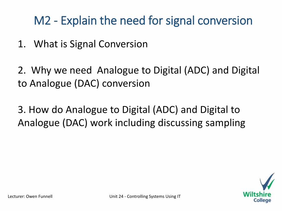
M2 - Explain the need for signal conversion
1. What is Signal Conversion
2. Why we need Analogue to Digital (ADC) and Digital to Analogue (DAC) conversion
3. How do Analogue to Digital (ADC) and Digital to Analogue (DAC) work including discussing sampling

Lecturer: Owen Funnell Unit 24 - Controlling Systems Using IT
M2 - Explain the need for signal conversionWhat is Signal Conversion
Signal Conversion is the process of changing one signal type to another. digital to analogue (DAC) and analogue to digital (ADC)A microphone takes sounds (analogue waves) which are then converted to digital for storing Theses Digital signals then need converting from digital back to analogue to play out of speaker.
ADC DAC
Why we need Analogue to Digital (ADC) and Digital to Analogue (DAC) conversion

Lecturer: Owen Funnell Unit 24 - Controlling Systems Using IT
M2 - Explain the need for signal conversion
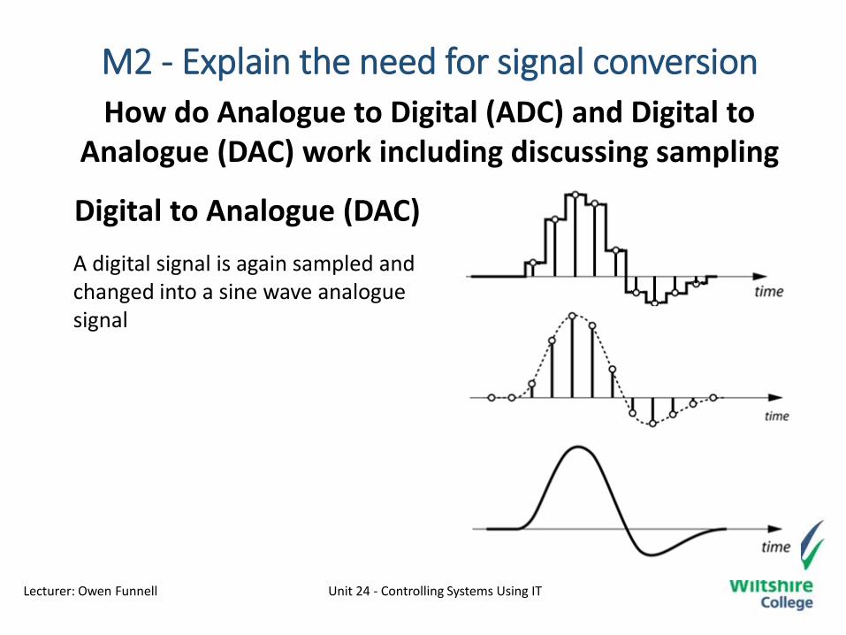
How do Analogue to Digital (ADC) and Digital to Analogue (DAC) work including discussing sampling
Analogue to Digital (ADC)
When an analogue signal is being converted it is first sampled Step 2.The sampled signal can then be converted into a digital format (Step3)Sample rate is the number of samples carried per second
Lecturer: Owen Funnell Unit 24 - Controlling Systems Using IT
M2 - Explain the need for signal conversion
How do Analogue to Digital (ADC) and Digital to Analogue (DAC) work including discussing sampling
Digital to Analogue (DAC)
A digital signal is again sampled and changed into a sine wave analogue signal

Lecturer: Owen Funnell Unit 24 - Controlling Systems Using IT
M2 - Explain the need for signal conversion
Not every pin on a microcontroller
has the ability to do analogue to
digital conversions. On the
Arduino board, these pins have
an ‘A’ in front of their label (A0
through A5) to indicate these pins
can read analogue voltages.