ANALOGOUS TAINTER-GATE FAILURES IN JAPAN AND USA
6
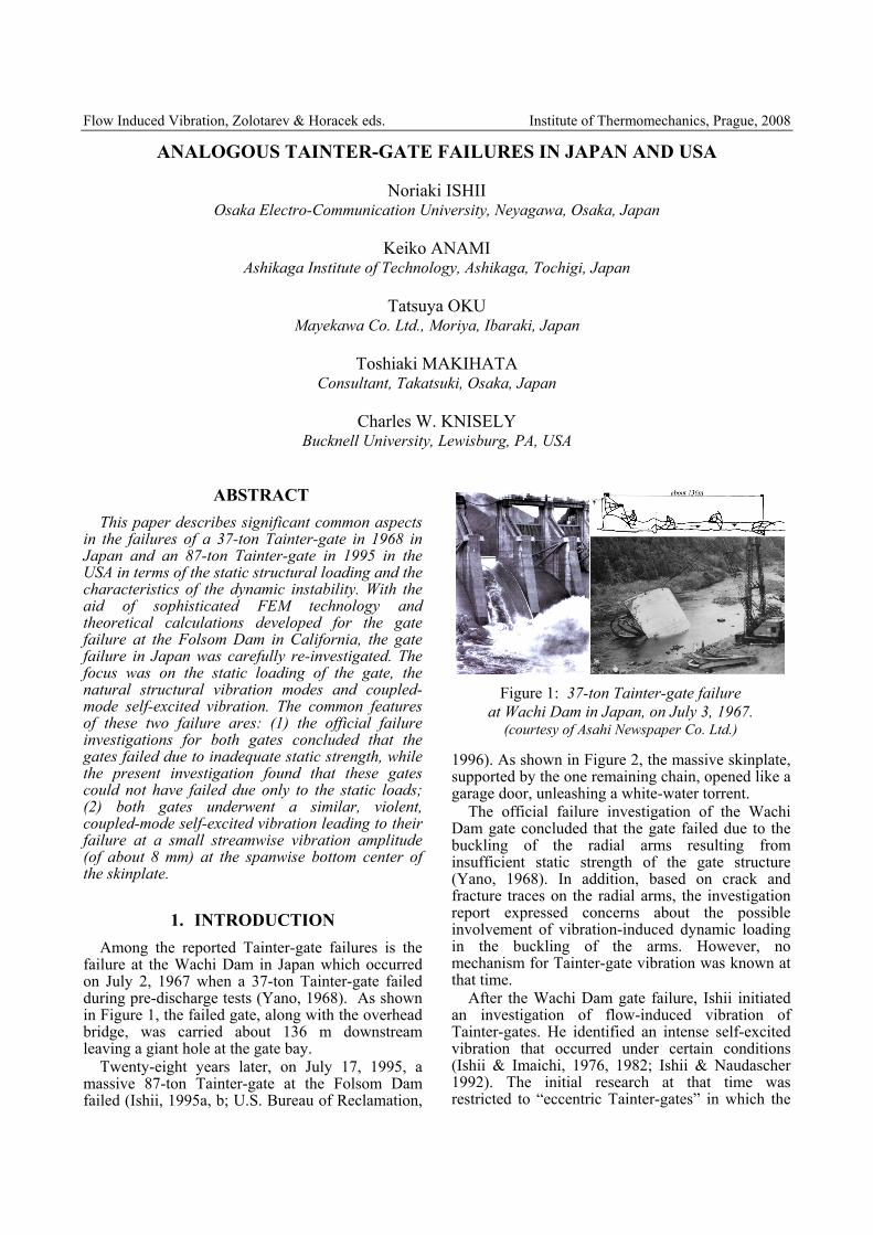
Flow Induced Vibration, Zolotarev & Horacek eds. Institute of Thermomechanics, Prague, 2008 ANALOGOUS TAINTER-GATE FAILURES IN JAPAN AND USA Noriaki ISHII Osaka Electro-Communication University, Neyagawa, Osaka, Japan Keiko ANAMI Ashikaga Institute of Technology, Ashikaga, Tochigi, Japan Tatsuya OKU Mayekawa Co. Ltd., Moriya, Ibaraki, Japan Toshiaki MAKIHATA Consultant, Takatsuki, Osaka, Japan Charles W. KNISELY Bucknell University, Lewisburg, PA, USA ABSTRACT This paper describes significant common aspects in the failures of a 37-ton Tainter-gate in 1968 in Japan and an 87-ton Tainter-gate in 1995 in the USA in terms of the static structural loading and the characteristics of the dynamic instability. With the aid of sophisticated FEM technology and theoretical calculations developed for the gate failure at the Folsom Dam in California, the gate failure in Japan was carefully re-investigated. The focus was on the static loading of the gate, the natural structural vibration modes and coupled- mode self-excited vibration. The common features of these two failure ares: (1) the official failure investigations for both gates concluded that the gates failed due to inadequate static strength, while the present investigation found that these gates could not have failed due only to the static loads; (2) both gates underwent a similar, violent, coupled-mode self-excited vibration leading to their failure at a small streamwise vibration amplitude (of about 8 mm) at the spanwise bottom center of the skinplate. 1. INTRODUCTION Among the reported Tainter-gate failures is the failure at the Wachi Dam in Japan which occurred on July 2, 1967 when a 37-ton Tainter-gate failed during pre-discharge tests (Yano, 1968). As shown in Figure 1, the failed gate, along with the overhead bridge, was carried about 136 m downstream leaving a giant hole at the gate bay. Twenty-eight years later, on July 17, 1995, a massive 87-ton Tainter-gate at the Folsom Dam failed (Ishii, 1995a, b; U.S. Bureau of Reclamation, 1996). As shown in Figure 2, the massive skinplate, supported by the one remaining chain, opened like a garage door, unleashing a white-water torrent. The official failure investigation of the Wachi Dam gate concluded that the gate failed due to the buckling of the radial arms resulting from insufficient static strength of the gate structure (Yano, 1968). In addition, based on crack and fracture traces on the radial arms, the investigation report expressed concerns about the possible involvement of vibration-induced dynamic loading in the buckling of the arms. However, no mechanism for Tainter-gate vibration was known at that time. After the Wachi Dam gate failure, Ishii initiated an investigation of flow-induced vibration of Tainter-gates. He identified an intense self-excited vibration that occurred under certain conditions (Ishii & Imaichi, 1976, 1982; Ishii & Naudascher 1992). The initial research at that time was restricted to “eccentric Tainter-gates” in which the Figure 1: 37-ton Tainter-gate failure at Wachi Dam in Japan, on July 3, 1967. (courtesy of Asahi Newspaper Co. Ltd.)
Transcript of ANALOGOUS TAINTER-GATE FAILURES IN JAPAN AND USA
Flow Induced Vibration, Zolotarev & Horacek eds. Institute of Thermomechanics, Prague, 2008
ANALOGOUS TAINTER-GATE FAILURES IN JAPAN AND USA
Noriaki ISHII Osaka Electro-Communication University, Neyagawa, Osaka, Japan
Keiko ANAMI
Ashikaga Institute of Technology, Ashikaga, Tochigi, Japan
Tatsuya OKU Mayekawa Co. Ltd., Moriya, Ibaraki, Japan
Toshiaki MAKIHATA
Consultant, Takatsuki, Osaka, Japan
Charles W. KNISELY Bucknell University, Lewisburg, PA, USA
ABSTRACT This paper describes significant common aspects
in the failures of a 37-ton Tainter-gate in 1968 in Japan and an 87-ton Tainter-gate in 1995 in the USA in terms of the static structural loading and the characteristics of the dynamic instability. With the aid of sophisticated FEM technology and theoretical calculations developed for the gate failure at the Folsom Dam in California, the gate failure in Japan was carefully re-investigated. The focus was on the static loading of the gate, the natural structural vibration modes and coupled-mode self-excited vibration. The common features of these two failure ares: (1) the official failure investigations for both gates concluded that the gates failed due to inadequate static strength, while the present investigation found that these gates could not have failed due only to the static loads; (2) both gates underwent a similar, violent, coupled-mode self-excited vibration leading to their failure at a small streamwise vibration amplitude (of about 8 mm) at the spanwise bottom center of the skinplate.
1. INTRODUCTION Among the reported Tainter-gate failures is the
failure at the Wachi Dam in Japan which occurred on July 2, 1967 when a 37-ton Tainter-gate failed during pre-discharge tests (Yano, 1968). As shown in Figure 1, the failed gate, along with the overhead bridge, was carried about 136 m downstream leaving a giant hole at the gate bay.
Twenty-eight years later, on July 17, 1995, a massive 87-ton Tainter-gate at the Folsom Dam failed (Ishii, 1995a, b; U.S. Bureau of Reclamation,
1996). As shown in Figure 2, the massive skinplate, supported by the one remaining chain, opened like a garage door, unleashing a white-water torrent.
The official failure investigation of the Wachi Dam gate concluded that the gate failed due to the buckling of the radial arms resulting from insufficient static strength of the gate structure (Yano, 1968). In addition, based on crack and fracture traces on the radial arms, the investigation report expressed concerns about the possible involvement of vibration-induced dynamic loading in the buckling of the arms. However, no mechanism for Tainter-gate vibration was known at that time.
After the Wachi Dam gate failure, Ishii initiated an investigation of flow-induced vibration of Tainter-gates. He identified an intense self-excited vibration that occurred under certain conditions (Ishii & Imaichi, 1976, 1982; Ishii & Naudascher 1992). The initial research at that time was restricted to “eccentric Tainter-gates” in which the
Figure 1: 37-ton Tainter-gate failure at Wachi Dam in Japan, on July 3, 1967.
(courtesy of Asahi Newspaper Co. Ltd.)

2
center of the skinplate is eccentric to the trunnion pin. Since the failed Wachi gate did not have any significant eccentricity, the consensus at the time was that the self-excited vibration mechanism identified by Ishii could not have actually occurred.
During the 28 years between the Wachi failure and that at Folsom, no progress was made in identifying a viable vibratory failure mechanism. At the time of the Folsom Dam gate failure, the gate operator clearly testified that a small vibration of increasing intensity was felt a few seconds before the gate failed. Immediately after the Folsom gate failure, Ishii was invited by the US Bureau of Reclamation (USBR) to investigate the cause of the gate failure. As a result of Ishii’s ensuing investigation, a new mechanism of gate failure was identified (Anami & Ishii, 2000; Anami, 2002; Ishii et al, 2005), to which any type of general non-eccentric Tainter-gate is susceptible. In this mechanism, the streamwise bending vibration of the skinplate becomes coupled with the whole gate vibration around the trunnion pin (see Figure 3) to produce a violent coupled-mode vibration. According to the theory, gate failure occurred at a small predicted amplitude of 8 mm of streamwise skinplate bending vibration, in the case of the Folsom gate.
With the identification of this coupled-mode self-excited vibration mechanism, one naturally wonders whether the gate failure 40 years ago in Japan might have also been due to this same mechanism. A re-investigation of the Wachi gate failure was undertaken using modern sophisticated FEM technologies and our theoretical calculations developed for the gate failure at Folsom dam to answer definitively this question.
This paper initially presents an overview of the Folsom gate failure investigations. Subsequently, results (the static stress, the static deformation and buckling) from a sophisticated FEM analysis of the Wachi gate are presented that show the gate could not possibly have failed due only to static loads. Finally, the natural vibration modes are identified with the FEM analysis and a detailed examination of the gate’s susceptibility to the coupled-mode self-excited vibration was conducted. The theory shows that the Wachi gate was also in a state of intense dynamic instability at the instant of its failure.
2. SUMMARY OF FAILURE ANALYSIS OF THE FOLSOM DAM TAINTER-GATE
In the Folsom Dam failure analysis, experimental modal analysis of one of the remaining geometrically similar Tainter-gates was carried out to establish the major vibration modes of the gate. As a result, two predominant in-air natural vibration
modes were identified, as shown in Figure 3. One mode was the rigid body vibration of the whole gate around the trunnion pin, with the frequency of 6.88 Hz, and other was the streamwise bending vibration mode of the skinplate, with the frequency of 26.9 Hz (Ishii, 1995b; Anami & Ishii, 1998a; 1998b).
With the gate exposed to flowing water, the 26.9 Hz in-air frequency of the streamwise bending mode is reduced to 6.46 Hz due, of course, to the water added mass effect. This in-water frequency is
Figure 2: 87-ton Tainter-gate failure at Folsom
Dam in USA, on July 17, 1995.
6.46Hz in water
×0.24
Chains
6.46Hz in water
×0.24
Chains
Figure 3: Two predominant in-air natural
vibration modes of the Folsom Tainter-gate.
0 0.5 1 1.5 20
0.05
0.1
Vibration frequency ratio γnw(≡Ωnwψ/Ωaθ)
Stab
ility
dam
ping
ratio
ζcψ
, ζcθ
StableStable
Unstable
0.94
ζcψ
ζcθ
0.051
0.002
ζaθ=0.012
: Folsom gate datum on its incipient failure
Synchronized with whole gate vib.
Synchronized with streamwise vib.
Figure 4: Dynamic stability criterion curve for the
failed Folsom Tainter-gate.

3
quite close to, but slightly lower than the rigid whole gate vibration frequency of 6.88 Hz.
Therefore, these two natural vibration modes can become well-coupled through inertial and hydrodynamic forces. This type of coupled-mode vibration is accompanied by a fluctuation in the gate’s discharge (i.e., a flow rate variation), that is capable of inducing violent self-excited vibrations (Anami & Ishii, 1999; 2000; 2003). A theoretical analysis of this coupled-mode self-excited vibration was undertaken to permit the calculation of the level of dynamic instability of Folsom gate at the instant of its failure, and to establish a dynamic design criteria for the gate (Anami, 2002). Figure 4 shows the stability damping ratio ζ needed to assure the dynamic stability of the gate plotted against the frequency ratio γnw of the skinplate in-water bending frequency to that of the rigid whole gate vibration. The measured inherent in-air damping ratio ζaψ = 0.002 for the failed Folsom gate is plotted at the measured frequency ratio of γnw = 0.94 (= 6.46/6.88) for the gate. The plotted data point is located just inside of the very sharp peak in the stability diagram, suggesting that the Folsom gate could have experienced an intense dynamic instability with an excitation ratio of 0.049 (= 0.051-0.002) resulting in the gate failure (Anami & Ishii, 1998a; Anami, 2002).
3. WACHI DAM TAINTER-GATE AND ITS OPERATION RECORD JUST
BEFORE FAILURE The configuration and major dimensions of the
Wachi Dam Tainter-gate, are shown in Figure 5, in which it can be seen that the skinplate, supported by three radial arms on each side, has a radius of about 13 m, a width of about 9 m and a height of about 12 m. The gate is π-shaped, with 8° inclined radial arms. The whole gate mass is about 37 ton.
The gate was operated for long periods at small gate openings with a gate submergence depth of 11.75 m, as shown in Figure 6. The gate failed while closing the gate from an opening of about 30 cm to zero.
4. STATIC FEM ANALYSES OF TENSILE FORCE AND BUCKLING
A precise FEM model of the Wachi gate was constructed on a computer using a powerful pre- and post-processing tool (FEMAP Ver.5. 00), as shown in Figure 7, where the gate is represented by 21,605 plate elements and 23,150 contact points. MacNeal-Schwendler’s MSC/N4W NASTRAN for Windows V3 was used in the present FEM analyses. To raise the calculation accuracy, the H method (the
element subdividing method) was adopted. The balance of the load of the elements was analyzed by the displacement method. The analysis included consideration of the friction at the trunnion shaft, with the maximum load of gate submergence depth of 12 m.
4.1 Deformation of radial arm
The downward displacement of radial arm #3 (the lowest arm) was calculated first. Figure 8 shows the calculated deformation of the arm for values of trunnion friction coefficient ranging from
1256
0
9000
1300
0
8°
(a) Side view (b) Top view Figure 5: Configuration and major dimensions of
“W” dam Tainter-gate.
0 5 10
5
10
15
20
0
10
20
30
40
50
60
Subm
erge
nce
dept
h [m
]
Ope
ning
hei
ght [
cm]
Operation time [h]
Submergence depth
Opening heightFailure
Figure 6: Record of gate submergence depth and
opening before failure.
Figure 7: FEM model of Wachi Dam Tainter-gate
4
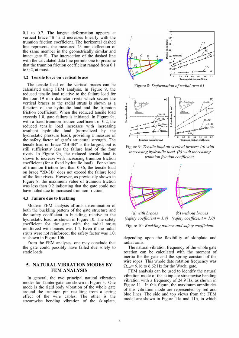
0.1 to 0.7. The largest deformation appears at vertical brace “B” and increases linearly with the trunnion friction coefficient. The horizontal dashed line represents the measured 23 mm deflection of the same member in the geometrically similar and intact gate #1. The intersection of the dashed line with the calculated data line permits one to presume that the trunnion friction coefficient ranged from 0.1 to 0.2, at most.
4.2 Tensile force on vertical brace
The tensile load on the vertical braces can be calculated using FEM analysis. In Figure 9, the reduced tensile load relative to the failure load for the four 19 mm diameter rivets which secure the vertical braces to the radial struts is shown as a function of the hydraulic load and the trunnion friction coefficient. When the reduced tensile load exceeds 1.0, gate failure is initiated. In Figure 9a, with a fixed trunnion friction coefficient of 0.2, the reduced tensile load increases with increasing resultant hydraulic load (normalized by the hydrostatic pressure load), providing a measure of the safety factor of gate’s structural strength. The tensile load on brace “2B-3B” is the largest, but is still sufficiently less the failure load of the four rivets. In Figure 9b, the reduced tensile load is shown to increase with increasing trunnion friction coefficient (for a fixed hydraulic load). For values of trunnion friction less than 0.36, the tensile load on brace “2B-3B” does not exceed the failure load of the four rivets. However, as previously shown in Figure 8, the maximum value of trunnion friction was less than 0.2 indicating that the gate could not have failed due to increased trunnion friction.
4.3 Failure due to buckling
Modern FEM analysis affords determination of both the buckling pattern of the gate structure and the safety coefficient in buckling, relative to the hydrostatic load, as shown in Figure 10. The safety coefficient for the gate with the radial struts reinforced with braces was 1.4. Even if the radial struts were not reinforced, the safety factor was 1.0, as shown in Figure 10b.
From the FEM analyses, one may conclude that the gate could possibly have failed due solely to static loads.
5. NATURAL VIBRATION MODES BY FEM ANALYSIS
In general, the two principal natural vibration modes for Tainter-gate are shown in Figure 3. One mode is the rigid body vibration of the whole gate around the trunnion pin resulting from a spring effect of the wire cables. The other is the streamwise bending vibration of the skinplate,
depending upon the flexibility of skinplate and radial arms.
The natural vibration frequency of the whole gate rotation can be calculated with the moment of inertia for the gate and the spring constant of the wire ropes This whole date rotation frequency was Ωnaθ= 6.16 to 6.62 Hz for the Wachi gate.
FEM analysis can be used to identify the natural vibration mode of the skinplate streamwise bending vibration with a frequency of 24.9 Hz, as shown in Figure 11. In this figure, the maximum amplitudes of this vibration mode are represented by red and blue lines. The side and top views from the FEM model are shown in Figure 11a and 11b, in which
BC AD#1
#2
#3
BC AD#1
#2
#3
0.1 0.2 0.3 0.4 0.5 0.6 0.7
0
10
20
30
40
50
60
70
Trunnion friction coefficient
Dis
plac
emen
t [m
m]
3A
3B
3C
3D
measured
0.1 0.2 0.3 0.4 0.5 0.6 0.70
10
20
30
40
50
60
70
Trunnion friction coefficient
Dis
plac
emen
t [m
m]
3A
3B
3C
3D
measured
Figure 8: Deformation of radial arm #3.
1 ABCD
23
1 2 30
1
2
Resultant hydraulic load
Red
uced
tens
ile lo
ad1C-2C
2C-3C
1B-2B
2B-3B
(a)1 ABCD
23
1 2 30
1
2
Resultant hydraulic load
Red
uced
tens
ile lo
ad1C-2C
2C-3C
1B-2B
2B-3B
(a)1 ABCD
23
0.1 0.2 0.3 0.4 0.5 0.6 0.70
1
2
Trunnion friction coefficient
Red
uced
tens
ile lo
ad
1C-2C
2C-3C
1B-2B
2B-3B
0.36
(b)1 ABCD
23
0.1 0.2 0.3 0.4 0.5 0.6 0.70
1
2
Trunnion friction coefficient
Red
uced
tens
ile lo
ad
1C-2C
2C-3C
1B-2B
2B-3B
0.36
(b)
Figure 9: Tensile load on vertical braces; (a) with increasing hydraulic load, (b) with increasing
trunnion friction coefficient.
(a) with braces (b) without braces
(safety coefficient = 1.4) (safety coefficient = 1.0)
Figure 10: Buckling pattern and safety coefficient.

5
the skinplate performs a streamwise bending vibration that is well-coupled with the spanwise vibration of radial arm structure, but not with the up- and down whole gate rotational vibration. For clear identification of the bending vibration mode, 8 horizontal cross-sectional views of the skinplate are shown in Figure 11c, in which the skinplate exhibits a 1-wavelength bending vibration mode with nodes at the joint of the radial arms and the skinplate. The increased amplitude toward the bottom is evident in Figure 11d where the amplitude of the spanwise center vertical cross-section of the skinplate is shown. Also in Figure 11d, a streamwise rotational vibration mode with a node at about 3/4 of the skinplate height is shown by the dashed lines.
6. COUPLED-MODE DYNAMIC INSTABILITY
6.1 Possible self-excited vibration mechanism
As schematically shown in Figure 12, if the bending rotational counter-clockwise vibration (1) of the skinplate, represented by ψ, is triggered by some random excitation, the counter-clockwise skinplate inertia torque (2) appears around the trunnion pin, thus exciting the counter-clockwise whole gate vibration (3), represented by θ. The gate opening under the gate increases (4), thus resulting in increased discharge water flow, and thus
decreasing the flow-rate-variation pressure (5) that feeds energy back to the skinplate bending rotational vibration (1). This closed-energy-cycle leads the gate to a violent coupled-mode self-excited vibration.
6.2 Dynamic instability
The identified coupled-mode vibration can be analyzed with our previously established theoretical analysis. The resulting dynamic stability criterion for the Wachi gate is shown in Figure 13 and is quite similar that for the Folsom gate, previously shown in Figure 4.
First, starting with the in-air natural vibration frequency of 24.9 Hz, and using the methods developed by Anami & Ishii (1999; 2000; 2003), the in-water natural vibration frequency with gate submergence depth of 12 m was calculated to be 5.68 Hz to 6.00 Hz. This in-water bending frequency corresponds to a natural vibration frequency ratio of 0.86 to 0.974 along the abscissa in Figure 13, for which there is a very high level essential dynamic instability, with excitation factors in the range 0.039 to 0.125.
(a) side view (b) 3D view
(c) amplitude at 8 sections (d) amplitude at the
of the skinplate spanwise center
Figure 11: In-air natural vibration mode of the skinplate, with a frequency of 24.9 Hz.
Figure 12: Mechanism of coupled-mode self-excited
vibration.
0 0.5 1 1.5 2
0.05
0.1
0.15
Natural vib. freq. ratio Ωnwψ/Ωnaθ
Exci
tatio
n ra
tioStableStable
Unstable
Unstable
0.039
0.125
0.86
0.974
Crit
ical
dam
ping
ratio
Figure 13: Dynamic stability criterion for the Wachi Dam Tainter-gate.

6
6.3 Minimum amplitude for gate failure
The violent skinplate streamwise vibration induces an excessive push-and-draw pressure due to inertia effect of water, which can destroy the gate. The resultant hydrodynamic load can be theoretically calculated for a given amplitude of skinplate motion at its bottom spanwise-center location, as shown in Figure 14. In this figure, the ordinate value of 1.41 corresponds to the safety coefficient from the FEM buckling analysis (see Figure 10a). The reduced skinplate vibration amplitude needed to reach this loading is 0.72×10⁻³ which corresponds to an amplitude of only 8.5 mm.
7. CONCLUSION The Wachi Dam Tainter-gate was thoroughly re-
examined yielding the following conclusions: (1) The safety coefficient for buckling of the radial
arm is 1.41, which indicates no possible failure only due to the hydrostatic load.
(2) The Wachi Dam Tainter-gate experienced violent coupled-mode self-excited vibration at a small gate opening.
(3) When the vibration amplitude of the skinplate bottom center reached only 8.5 mm, the hydrodynamic load on the gate structure, due to inertia effect of the enormous water mass, exceeded its buckling safety factor of 1.41, and the gate instantly failed.
8. REFERENCES Anami, K., 2002, Flow- Induced Coupled- Mode Self Excited Vibration of Large-Scaled Tainter-Gates, Dissertation submitted to Osaka Electro- Communication University, (in Japanese: Translated into English on Dec. 2005).
Anami, K. & Ishii, N., 1998a, In-Water Streamwise Vibration of Folsom Dam Radial Gates in California, Proceedings of ASME Pressure Vessels and Piping Conference, Vol. 363, pp.87-94.
Anami, K. & Ishii, N., 1998b, In-Air and In-Water Natural Vibrations of Folsom Dam Radial Gate in California, In Experimental Mechanics 1 (Advances in design, testing and analysis) (ed. Allison I.M.), pp.29-34: Balkema
Anami, K. & Ishii, N., 1999, Flow-Induced Coupled-Mode-Vibration of Folsom Dam Tainter-Gates in California, Proceedings of ASME Pressure Vessels and Piping Conference, Vol. 396, pp.343-350.
Anami, K. & Ishii, N., 2000, Flow-Induced Dynamic Instability Closely Related to Folsom Dam Tainter-Gate Failure in California, In Flow Induced Vibration (eds: Ziada S. & Staubli T.), pp.205-212: Balkema.
Anami, K. & Ishii, N., 2003, Model Tests for Non-Eccentricity Dynamic Instability Closely Related to Folsom Dam Tainter-Gate Failure, Proceedings of ASME Pressure Vessels and Piping Conference, Vol.465, pp.213-221.
U.S. Bureau of Reclamation, 1996, Forensic Report on Spillway Gate 3 Failure Folsom Dam, Bureau of Reclamation Mid-Pacific Regional Office Sacramento, California (Nov. 18, 1996).
Ishii, N., 1995a, Folsom Dam Gate Failure Evaluation and Suggestion, 1st report submitted to the U.S. Bureau of Reclamation (August 24, 1995).
Ishii, N., 1995b, Folsom Dam Gate Failure Evaluation Based on Modal Analysis and Suggestion, 2nd report submitted to U.S. Bureau of Reclamation (Nov. 8, 1995).
Ishii, N., Anami, K. & Knisely, C.W., 2005, Lessons from Folsom Dam Tainter-Gate Failure and Future Work for Subsequent Generations, Final report submitted to the U.S. Bureau of Reclamation, (Dec. 08, 2005).
Ishii, N. & Imaichi, K., 1976, Instability of an Idealized Tainter-Gate System without Damping Caused by Surface Waves on the Backwater of Dam, Transactions of the Japan Society of Mechanical Engineers, 42-364, pp.3853-3861. (in Japanese)
Ishii, N &, Imaichi, K., 1982, Instability of elastically suspended Tainter-gate system caused by surface waves on the reservoir of a dam (Approximate Solution), Transactions of the Japan Society of Mechanical Engineers, B, 48-428, pp.640-647. (in Japanese)
Ishii, N. & Naudascher, E., 1992, A Design Criterion for Dynamic Stability of Tainter-gates, Journal of Fluids and Structures, Vol.6, No.1, pp.67-84.
Yano, K., 1968, “W” Dam Tainter-gate failure, Annual report of Disaster Prevention Research Institute Kyoto University, No.11, B, pp.203-219. (in Japanese)
0 1 2 3 4 5
1.0
2.0
3.0
4.0
5.0
Reduced amplitude, RSΨ0/d0[×10−3]
Red
uced
resu
ltant
hyd
raul
ic lo
ad
(rs=0.72; F=39.2)
1.41
(→St
ream
wis
e vi
b.
inducing failure load
am
plitu
de 8
.5 m
m)
of W dam Tainter−gate
0.72
Figure 14: Resultant hydraulic load on the Wachi Dam Tainter-gate, suggesting skinplate vibration
for gate failure.