![At125 Kopa Anti tamper ip65 reflectorkopaglobal.com/assets/at125.pdf · At125 Kopa Anti tamper ip65 reflector CRI >95, COI, ... Emax[lx] = Lux level at ... 811 LUMEN K0718 38º 4K](https://static.fdocuments.in/doc/165x107/5b5d38a27f8b9ad2198de69f/at125-kopa-anti-tamper-ip65-at125-kopa-anti-tamper-ip65-reflector-cri-95-coi.jpg)
AN1247: Anti-Tamper Protection Configuration and Use
37
AN1247: Anti-Tamper Protection Configuration and Use This application note describes how to program, provision, and configure the Secure Engine anti-tamper module. Many aspects of the anti-tamper module, including disabling the anti-tamper re- sponse when needed, are discussed. The anti-tamper module is only available on Secure Vault High devices. KEY POINTS • Tamper responses • Tamper sources • Tamper configuration • Tamper disable • Examples of provisioning and disabling the anti-tamper module silabs.com | Building a more connected world. Rev. 0.2
Transcript of AN1247: Anti-Tamper Protection Configuration and Use

AN1247: Anti-Tamper ProtectionConfiguration and Use
This application note describes how to program, provision, andconfigure the Secure Engine anti-tamper module. Many aspectsof the anti-tamper module, including disabling the anti-tamper re-sponse when needed, are discussed.The anti-tamper module is only available on Secure Vault High devices.
KEY POINTS
• Tamper responses• Tamper sources• Tamper configuration• Tamper disable• Examples of provisioning and disabling
the anti-tamper module
silabs.com | Building a more connected world. Rev. 0.2

1. Series 2 Device Security Features
Protecting IoT devices against security threats is central to a quality product. Silicon Labs offers several security options to help devel-opers build secure devices, secure application software, and secure paths of communication to manage those devices. Silicon Labs’security offerings were significantly enhanced by the introduction of the Series 2 products that included a Secure Engine. The SecureEngine is a tamper-resistant component used to securely store sensitive data and keys and to execute cryptographic functions andsecure services.
On Series 1 devices, the security features are implemented by the TRNG (if available) and CRYPTO peripherals.
On Series 2 devices, the security features are implemented by the Secure Engine and CRYPTOACC (if available). The Secure Enginemay be hardware-based, or virtual (software-based). Throughout this document, the following abbreviations are used:• HSE - Hardware Secure Engine• VSE - Virtual Secure Engine• SE - Secure Engine (either HSE or VSE)
Additional security features are provided by Secure Vault. Three levels of Secure Vault feature support are available, depending on thepart and SE implementation, as reflected in the following table:
Level (1) SE Support Part (2)
Secure Vault High (SVH) HSE only (HSE-SVH) EFR32xG2yB (3)
Secure Vault Mid (SVM) HSE (HSE-SVM) EFR32xG2yA (3)
" VSE (VSE-SVM) EFR32xG2y, EFM32PG2y (4)
Secure Vault Base (SVB) N/A MCU Series 1 and Wireless SoC Series 1
Note:1. The features of different Secure Vault levels can be found in https://www.silabs.com/security.2. The x is a letter (B, F, M, or Z).3. At the time of this writing, the y is a digit (1 or 3).4. At the time of this writing, the y is a digit (2).
Secure Vault Mid consists of two core security functions:• Secure Boot: Process where the initial boot phase is executed from an immutable memory (such as ROM) and where code is au-
thenticated before being authorized for execution.• Secure Debug access control: The ability to lock access to the debug ports for operational security, and to securely unlock them
when access is required by an authorized entity.
Secure Vault High offers additional security options:• Secure Key Storage: Protects cryptographic keys by “wrapping” or encrypting the keys using a root key known only to the HSE-SVH.• Anti-Tamper protection: A configurable module to protect the device against tamper attacks.• Device authentication: Functionality that uses a secure device identity certificate along with digital signatures to verify the source or
target of device communications.
A Secure Engine Manager and other tools allow users to configure and control their devices both in-house during testing and manufac-turing, and after the device is in the field.
AN1247: Anti-Tamper Protection Configuration and UseSeries 2 Device Security Features
silabs.com | Building a more connected world. Rev. 0.2 | 2

1.1 User Assistance
In support of these products Silicon Labs offers whitepapers, webinars, and documentation. The following table summarizes the keysecurity documents:
Document Summary Applicability
AN1190: Series 2 Secure Debug How to lock and unlock Series 2 debug access, includingbackground information about the SE
Secure Vault Mid and High
AN1218: Series 2 Secure Boot withRTSL
Describes the secure boot process on Series 2 devices usingSE
Secure Vault Mid and High
AN1247: Anti-Tamper Protection Con-figuration and Use (this document)
How to program, provision, and configure the anti-tampermodule
Secure Vault High
AN1268: Authenticating Silicon LabsDevices using Device Certificates
How to authenticate a device using secure device certificatesand signatures, at any time during the life of the product
Secure Vault High
AN1271: Secure Key Storage How to securely “wrap” keys so they can be stored in non-volatile storage.
Secure Vault High
AN1222: Production Programming ofSeries 2 Devices
How to program, provision, and configure security informationusing SE during device production
Secure Vault Mid and High
1.2 Key Reference
Public/Private keypairs along with other keys are used throughout Silicon Labs security implementations. Because terminology cansometimes be confusing, the following table lists the key names, their applicability, and the documentation where they are used.
Key Name Customer Programmed Purpose Used in
Public Sign key (Sign Key Public) Yes Secure Boot binary authentication and/or OTAupgrade payload authentication
AN1218 (primary),AN1222
Public Command key (CommandKey Public)
Yes Secure Debug Unlock or Disable Tamper com-mand authentication
AN1190 (primary),AN1222, AN1247
OTA Decryption key (GBL De-cryption key) aka AES-128 Key
Yes Decrypting GBL payloads used for firmware up-grades
AN1222 (primary),UG266
Attestation key aka Private De-vice Key
No Device authentication for secure identity AN1268
AN1247: Anti-Tamper Protection Configuration and UseSeries 2 Device Security Features
silabs.com | Building a more connected world. Rev. 0.2 | 3

2. Device Compatibility
This application note supports Series 2 device families (HSE-SVH), and some functionality is different depending on the device.
Wireless SoC Series 2 families (HSE-SVH) consist of:• EFR32BG21B/EFR32MG21B• EFR32FG23B/EFR32ZG23B
AN1247: Anti-Tamper Protection Configuration and UseDevice Compatibility
silabs.com | Building a more connected world. Rev. 0.2 | 4

3. Introduction
The HSE-SVH Anti-Tamper module is used to hamper or prevent both reverse engineering and re-engineering of proprietary softwaresystems or applications.
Tamper attacks come from one or more vectors. Common attacks include voltage glitching, magnetic interference, and forced tempera-ture adjustment. The HSE-SVH Anti-Tamper module provides fast hardware detection of external tamper signals such as case opening,glitching, and logical attacks allowing analysis and escalation up to and including bricking the device.
The anti-tamper module connects a number of hardware and software-driven tamper signals to a set of configurable hardware and soft-ware responses. This can be used to program the device to automatically respond to external events that could signal that someone istrying to tamper with the device, and very rapidly remove secrets stored in the HSE.
The available tamper signals range from signals based on failed authentication and secure boot to specialized glitch detectors. Whenany of these signals fire, the tamper block can be configured to trigger several different responses, ranging from triggering an interruptto erasing the One-Time-Programmable (OTP) memory, removing all HSE secrets and resulting in a permanently destroyed device.
AN1247: Anti-Tamper Protection Configuration and UseIntroduction
silabs.com | Building a more connected world. Rev. 0.2 | 5

4. Secure Engine Manager
The Secure Engine Manager provides thread-safe APIs for the SE's mailbox interface. The SE Manager APIs related to tamper opera-tions are listed in the following table.
For the SE's mailbox interface, see section "Secure Engine Subsystem" in AN1190: Series 2 Secure Debug.
Table 4.1. SE Manager API for Tamper Operations
SE Manager API Usage
sl_se_init_otp Initialize SE OTP configuration (including tamper configuration on HSE-SVH devices).
sl_se_read_otp Read SE OTP configuration (including tamper configuration on HSE-SVH devices).
sl_se_init_otp_key Used during device initialization to upload the Public Command Key.
sl_se_read_pubkey Read the stored Public Command Key.
sl_se_get_serialnumber Read out the serial number (16 bytes) of the HSE device.
sl_se_get_challenge Read out the current challenge value (16 bytes) for tamper disable.
sl_se_roll_challenge Used to roll the current challenge value (16 bytes) to invalidate the Disable Tamper Token.
sl_se_disable_tamper Temporarily disable tamper configuration using the Disable Tamper Token.
sl_se_get_status Read the current HSE status (including recorded tamper status on HSE-SVH devices).
sl_se_get_reset_cause Read the EMU->RSTCAUSE register from HSE devices after a tamper reset.
Note:• The sl_se_get_reset_cause is only available on EFR32xG21B devices. It can directly read the EMU->RSTCAUSE register on oth-
er HSE-SVH devices.• The SE Manager API document can be found at https://docs.silabs.com/gecko-platform/latest/service/api/group-sl-se-manager.
AN1247: Anti-Tamper Protection Configuration and UseSecure Engine Manager
silabs.com | Building a more connected world. Rev. 0.2 | 6

5. Tamper Responses
A tamper source can lead to a series of different autonomous responses from the HSE. These responses are listed in the followingtable.
Table 5.1. Tamper Responses
Level (1) Response (2) Description
0 Ignore No action is taken
1 Interrupt Triggers the SETAMPERHOST interrupt on the host
2 Filter Increases a counter in the tamper filter
4 Reset Resets the device
7 Erase OTP Erases the device's OTP configuration
Note:1. Level 3, 5, and 6 are reserved.2. These responses are cumulative, meaning that if a filter response is triggered, an interrupt will also be triggered.
5.1 Interrupt
If a tamper source is configured to respond with the interrupt response or higher (≥ level 1), the SETAMPERHOST interrupt line to the hostCortex-M33 will be pulsed and make the NVIC trigger the corresponding interrupt handler (SETAMPERHOST_IRQHandler).
After the interrupt has been handled, the tamper status can be found by reading the HSE status (using sl_se_get_status in the SEManager), which contains a list of all the tamper sources that have been triggered since the last time the status was read. Reading HSEstatus clears the registered tamper sources.
Note: It requires enabling the SEMAILBOXHOST clock for tamper source to trigger the SETAMPERHOST interrupt in some HSE-SVH devices(like EFR32xG23B).
5.2 Filter
The HSE has a filter that can be used to filter out spurious tamper events. The filter has a counter that is periodically reset. If a tampersource is configured to the filter level (level 2), when it is triggered, the counter is increased. If the counter value reaches a configurablethreshold, the Filter counter tamper source (number 1) is triggered, which can be configured to lead to any of the other responses.
Only a single shared filter counter is available, so the cumulative triggering of all tamper sources configured to the filter level will in-crease the same counter. The filter can be configured to use one of the trigger thresholds and reset periods provided below. The filtercounter is reset upon a tamper reset.
Filter Trigger Threshold• Value (n): 0 to 7• Filter Trigger Threshold: 256/2n (256 to 2)
Filter Reset Period• Value (n): 0 to 31• Filter Reset Period: 32 ms * 2n (32 ms to ~795.4 days)
AN1247: Anti-Tamper Protection Configuration and UseTamper Responses
silabs.com | Building a more connected world. Rev. 0.2 | 7

5.3 Reset
The reset response resets the HSE and Cortex-M33. After a tamper reset, the last reset cause can be directly read from EMU->RSTCAUSE register or using sl_se_get_rstcause in the SE Manager.
If a tamper reset is triggered during boot, this can lead to a boot loop. To debug such a scenario, the HSE has a tamper reset counterand enters diagnostic mode if the counter reaches a programmable threshold. Users can issue a non-tamper reset to clear the tamperreset counter before the programmable threshold is reached.
In diagnostic mode, the Cortex-M33 is held in reset and only DCI commands are available. The device will remain in diagnostic modeuntil a power-on or pin reset occurs.
For SE's DCI interface, see section "Secure Engine Subsystem" in AN1190: Series 2 Secure Debug.
5.4 Erase OTP
The Erase OTP response is the strongest reaction the HSE can take, and it will make the device and all wrapped secrets unrecovera-ble. After this response, the device will no longer be able to boot.
This response should typically only be used in situations where the device believes that it is under an actual attack, for instance throughthe detection of several voltage or digital glitches in a short time window.
AN1247: Anti-Tamper Protection Configuration and UseTamper Responses
silabs.com | Building a more connected world. Rev. 0.2 | 8

6. Tamper Sources
The HSE determines the minimum tamper level for each tamper source. It always enables the tamper sources which have the defaultlevel higher than 0. Users may escalate the tamper response of any source when initially configuring the part. The following tables listthe available tamper sources and the default level (response) on the EFR32xG21B and other HSE-SVH devices.
Table 6.1. Tamper Sources on the EFR32xG21B Devices
Type Number Name Description Default Level
SE Hardware 0 Reserved — —
" 1 Filter counter Filter counter reached the configured threshold value 0 (Ignore)
" 2 SE watchdog Internal SE watchdog expired 4 (Reset)
" 3 Reserved — —
" 4 SE RAM CRC SE RAM parity error occurred 4 (Reset)
" 5 SE hard fault SE core hard fault occurred 4 (Reset)
" 6 Reserved — —
SE Software 7 SE software assertion SE software triggered an assertion 4 (Reset)
" 8 SE secure boot Secure boot of SE firmware failed 4 (Reset)
" 9 User secure boot Secure boot of host firmware failed 0 (Ignore)
" 10 Mailbox authorization Unauthorized command received over the Mailbox interface 0 (Ignore)
" 11 DCI authorization Unauthorized command received over the DCI interface 0 (Ignore)
" 12 OTP read OTP or flash content could not be properly authenticated 4 (Reset)
" 13 Reserved — —
" 14 Self test Integrity error of internal storage was detected 4 (Reset)
" 15 TRNG monitor TRNG monitor detected a lack of entropy 0 (Ignore)
Hardware 16 - 23 PRS0 - 7 PRS channel 0 - 7 asserted 0 (Ignore)
" 24 Decouple BOD Decouple Brown-Out-Detector threshold alert 4 (Reset)
" 25 Temperature sensor On-chip temperature sensor detected a temperature outsidethe operational conditions of the device
0 (Ignore)
" 26 Voltage glitch falling Voltage glitch detector detected a falling glitch 0 (Ignore)
" 27 Voltage glitch rising Voltage glitch detector detected a rising glitch 0 (Ignore)
" 28 Secure lock Debug lock internal logic check failed 4 (Reset)
" 29 SE debug SE debug granted 0 (Ignore)
" 30 Digital glitch Digital glitch detector detected an event 0 (Ignore)
" 31 SE ICACHE SE instruction cache checksum error 4 (Reset)
Table 6.2. Tamper Sources on Other HSE-SVH Devices
Type Number Name Description Default Level
SE Hardware 0 Reserved — —
" 1 Filter counter Filter counter reached the configured threshold value 0 (Ignore)
" 2 SE watchdog Internal SE watchdog expired 4 (Reset)
AN1247: Anti-Tamper Protection Configuration and UseTamper Sources
silabs.com | Building a more connected world. Rev. 0.2 | 9

Type Number Name Description Default Level
" 3 Reserved — —
" 4 SE RAM ECC2 SE RAM 2-bit ECC error occurred 4 (Reset)
" 5 SE hard fault SE core hard fault occurred 4 (Reset)
" 6 Reserved — —
SE Software 7 SE software assertion SE software triggered an assertion 4 (Reset)
" 8 SE secure boot Secure boot of SE firmware failed 4 (Reset)
" 9 User secure boot Secure boot of host firmware failed 0 (Ignore)
" 10 Mailbox authorization Unauthorized command received over the Mailbox interface 0 (Ignore)
" 11 DCI authorization Unauthorized command received over the DCI interface 0 (Ignore)
" 12 OTP read OTP or flash content could not be properly authenticated 4 (Reset)
" 13 Reserved — —
" 14 Self test Integrity error of internal storage was detected 4 (Reset)
" 15 TRNG monitor TRNG monitor detected a lack of entropy 0 (Ignore)
Hardware 16 Secure lock Debug lock internal logic check failed 4 (Reset)
" 17 Digital glitch Digital Glitch detector detected an event 0 (Ignore)
" 18 Voltage glitch Voltage Glitch Detector detected an event 0 (Ignore)
" 19 SE ICACHE SE instruction cache checksum error 4 (Reset)
" 20 SE RAM ECC1 SE RAM 1-bit ECC error occurred 0 (Ignore)
" 21 BOD Brown-Out-Detector threshold alert 4 (Reset)
" 22 Temperature sensor On-chip temperature sensor detected a temperature outsidethe operational conditions of the device
0 (Ignore)
" 23 DPLL fall DPLL lock failed low 0 (Ignore)
" 24 DPLL rise DPLL lock failed high 0 (Ignore)
" 25 - 31 PRS0 - 6 PRS channel 0 - 6 asserted 0 (Ignore)
Note:• In EFR32xG21B devices, hardware tamper sources 24 to 27 can operate down to Energy Mode 3 (EM3), whereas other hardware
tamper sources (16 - 23 and 28 - 31) can be active down to Energy Mode 1 (EM1). All hardware tamper sources (16 - 31) in otherHSE-SVH devices can operate down to EM1.
• User configuration or tamper disable cannot reduce the tamper response below the default Level.• The User secure boot source gets triggered if secure boot is enabled and host image verification fails. It is likely to put the device in
the boot loop if users escalate the tamper response of this source to 4 (Reset).• PRS inputs can allow user applications to implement additional tamper sources and feed them into the tamper response mecha-
nism. The PRS tamper sources are under the control of the user application and could be reconfigured or disabled if the user appli-cation is compromised.
• The Temperature sensor source is not completely accurate and is generally only suitable for systems that expect to stay well withinthe specified temperature range. Users requiring a tighter temperature limit can implement their temperature monitor and provide theresults as a tamper source via PRS.
AN1247: Anti-Tamper Protection Configuration and UseTamper Sources
silabs.com | Building a more connected world. Rev. 0.2 | 10

7. Anti-Tamper Configuration
The anti-tamper configuration is one-time programmable (OTP). The HSE OTP is provisioned by sl_se_init_otp in the SE Manager.It means that tamper configuration must be written together with secure boot settings; and are immutable after they are written. Thefollowing table lists the tamper configuration.
For secure boot settings and tamper configuration, see section "Enabling Secure Boot and Tamper Configuration" in AN1222: Produc-tion Programming of Series 2 Devices.
Table 7.1. Anti-Tamper Configuration
Setting Description
Tamper response levels A response level for each tamper source (1)
Filter settings The tamper filter counter has two settings: trigger threshold and reset period
Flags Digital Glitch Detector Always On (bit 1): 0 — Digital glitch detector runs when the HSE is executing acommand; 1 — Digital glitch detector runs continually even when the HSE is not performing any op-erations (2)
Reset threshold The number of consecutive tamper resets (up to 255) before the part enters diagnostic mode (3)
Note:1. It is not possible to degrade the default level of a tamper source, so if a response is set to a lower level than the default level, this
will not have any effect.2. This leads to increased energy consumption.3. If the threshold is set to 0, the part will never enter the diagnostic mode due to tamper reset.
AN1247: Anti-Tamper Protection Configuration and UseAnti-Tamper Configuration
silabs.com | Building a more connected world. Rev. 0.2 | 11

8. Usage Example
Several of the available tamper sources report internal HSE errors. It configures the anti-tamper module to reset the device (level 4) bydefault if any of a number of these HSE errors are detected. Custom handling of internal and external tamper sources (default level 0)can be configured to trigger an interrupt (level 1) on the Cortex-M33 or increase a counter in the tamper filter (level 2) as in the followingfigure for EFR32xG21B devices.
Level 2 (Filter)
Level 1 (Interrupt)29 SE Debug
14 TRNG Monitor
26 Voltage Glitch Falling
30 Digital Glitch
25 Temperature Sensor
10 Mailbox Authorization
27 Voltage Glitch Rising
Filter > 50 % errors
SE debug unlocked?Filter > 1 % errors
> 1 min Out of specification
Noise filter
Noise filter
Noise filter
16 PRS Tamper (Reset)
YesHealth reportingNo
Health reporting
17 PRS Tamper – GPIO to detect enclosure opening
2 Filter counter (Reset)
Figure 8.1. Custom Handling of Tamper Sources (EFR32xG21B Devices)
Usage example highlights:• The SE debug triggers an interrupt when an attempt to open the SE debug port occurs; further action depends on debug port status.• The response of the TRNG monitor depends on the failure rate due to lack of entropy.• The voltage and digital glitch detectors can see spurious activations. They should typically not be used to drive a high-level tamper
response directly. Instead, they should feed their signals into a tamper interrupt, which activates a high-level action (like Reset in thisexample) through PRS tamper if a certain number of detections (noise filter) occur in a short time window.
• The operating conditions decide the time out of the specification filter for the temperature sensor. For some systems, any time out ofspecification should trigger a reset.
• Mailbox authorization is handled similarly for voltage and digital glitch detectors.• A PRS tamper implements a high-level response for a tamper interrupt, which issues a tamper reset (level 4) to prevent or slow
further attacks.• In extreme cases, if the system identifies an attack with high confidence, a PRS tamper can be configured as Erase OTP (level 7) to
brick the part and prevent further attacks. It recommends only when the destruction of parts is acceptable with high confidence of anattack can be achieved.
• Another PRS tamper detects enclosure opening from GPIO. This source feeds into the tamper filter counter (level 2), which will acti-vate a Filter counter (number 1) response (Reset in this example) if the filter counter reaches the trigger threshold within the filterreset period. It is less flexible than the interrupt response approach since the trigger threshold and filter reset period are one-timeprogrammable.
AN1247: Anti-Tamper Protection Configuration and UseUsage Example
silabs.com | Building a more connected world. Rev. 0.2 | 12

9. Tamper Disable
For diagnostic purposes, it may be necessary to disable the tamper response, for example, if a user has configured the part to EraseOTP on external tamper detection. Disabling the tamper response is required to open the unit and perform failure analysis or field serv-ice activities.
After tamper configuration has been initialized, users can temporarily restore the tamper response for a set of tamper sources via a Disable Tamper Token authenticated against the Public Command Key in HSE OTP (similar to secure debug unlock). It is only possibleif the Public Command Key has been provisioned in the device.
Figure 9.1. Tamper Disable on the EFR32xG21B Devices
Figure 9.2. Tamper Disable on Other HSE-SVH Devices
AN1247: Anti-Tamper Protection Configuration and UseTamper Disable
silabs.com | Building a more connected world. Rev. 0.2 | 13

9.1 Disable Tamper Token
The elements of the Disable Tamper Token are described in the following figures and table.
Disable tamper command (4 bytes)
Access certificate(156 bytes)
Disable tamper command signature
(64 bytes)
Tamper disable mask (4 bytes)
Command payload
Commandword
Commandparameter
Figure 9.3. Disable Tamper Token
Table 9.1. Elements of Disable Tamper Token
Element Value Description
Disable tamper command 0xfd020001 The command word of the Disable Tamper Token.
Tamper disable mask Device-dependent The command parameter of the Disable Tamper Token.
Access certificate (1) Device-dependent See section Access Certificate.
Disable tamper command signature (1) Device-dependent See section Challenge Response.
Note:1. The disable tamper command payload consists of an access certificate and a disable tamper command signature.
Figure 9.4. Tamper Disable Mask
Note: Set bit to restore the default response of the corresponding tamper source.
The Disable Tamper Token temporarily reverts all masked tamper sources in the figure above to the hard-coded configuration (Figure9.1 Tamper Disable on the EFR32xG21B Devices on page 13 and Figure 9.2 Tamper Disable on Other HSE-SVH Devices on page13).
The Disable Tamper Token can only undo the user level configuration. It cannot degrade the default level of a tamper source.
AN1247: Anti-Tamper Protection Configuration and UseTamper Disable
silabs.com | Building a more connected world. Rev. 0.2 | 14

9.2 Access Certificate
The elements of the access certificate are described in the following figure and table.
Magic word(4 bytes)
Authorizations(4 bytes)
Serial number(16 bytes)
Public Certificate Key (64 bytes)
Access certificate signature (64 bytes)
Tamper authorizations
(4 bytes)Signed by
Private Command Key
Figure 9.5. Access Certificate
Table 9.2. Elements of the Access Certificate
Element Value Description
Magic word 0xe5ecce01 A constant value used to identify the access certificate.
Authorizations 0x0000003e (1) A value used to authorize which bit in the debug mode request can be enabledfor secure debug.
Tamper Authorizations 0xffffffb6 (2) A value used to authorize which bit in the tamper disable mask can be enabled todisable the tamper response.
Serial number Device-dependent A number used to compare against the on-chip serial number for secure debugor tamper disable.
Public Certificate Key (3) Device-dependent The public key corresponding to the Private Certificate Key (3) used to generatethe signature (ECDSA-P256-SHA256) in a challenge response.
Access certificate signature Device-dependent All the content above is signed (ECDSA-P256-SHA256) by the Private Com-mand Key corresponding to the Public Command Key in the HSE OTP.
Note:1. Value that allows full debug access for secure debug.2. Value that enables available bits in the tamper disable mask for tamper disable.3. The Private/Public Certificate Key is a randomly generated key pair. It can be ephemeral or retainable.
The Private Certificate Key can be used repeatedly to generate the signature in a challenge response on one device until the Private/Public Certificate Key pair is discarded. This can reduce the frequency of access to the Private Command Key, allowing more restrictiveaccess control on that key.
For more information about secure debug, see AN1190: Series 2 Secure Debug.
AN1247: Anti-Tamper Protection Configuration and UseTamper Disable
silabs.com | Building a more connected world. Rev. 0.2 | 15
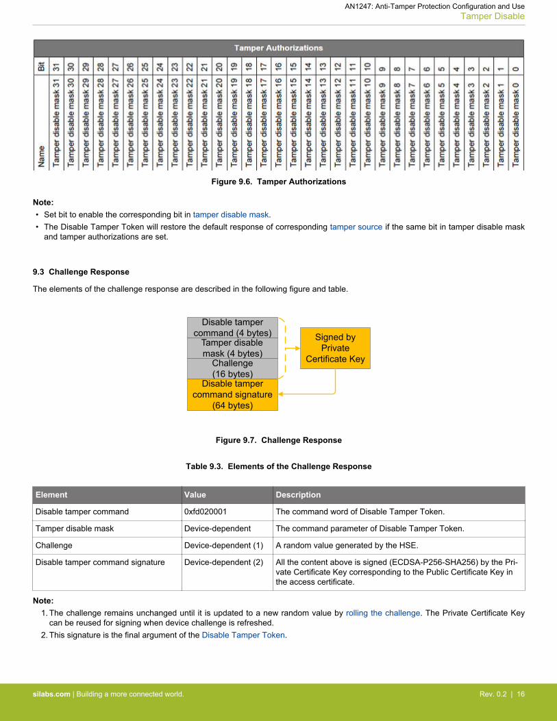
Figure 9.6. Tamper Authorizations
Note:• Set bit to enable the corresponding bit in tamper disable mask.• The Disable Tamper Token will restore the default response of corresponding tamper source if the same bit in tamper disable mask
and tamper authorizations are set.
9.3 Challenge Response
The elements of the challenge response are described in the following figure and table.
Disable tamper command (4 bytes)
Tamper disable mask (4 bytes)
Challenge(16 bytes)
Disable tamper command signature
(64 bytes)
Signed by Private
Certificate Key
Figure 9.7. Challenge Response
Table 9.3. Elements of the Challenge Response
Element Value Description
Disable tamper command 0xfd020001 The command word of Disable Tamper Token.
Tamper disable mask Device-dependent The command parameter of Disable Tamper Token.
Challenge Device-dependent (1) A random value generated by the HSE.
Disable tamper command signature Device-dependent (2) All the content above is signed (ECDSA-P256-SHA256) by the Pri-vate Certificate Key corresponding to the Public Certificate Key inthe access certificate.
Note:1. The challenge remains unchanged until it is updated to a new random value by rolling the challenge. The Private Certificate Key
can be reused for signing when device challenge is refreshed.2. This signature is the final argument of the Disable Tamper Token.
AN1247: Anti-Tamper Protection Configuration and UseTamper Disable
silabs.com | Building a more connected world. Rev. 0.2 | 16

9.4 Tamper Disable Flow
The tamper disable flow is described in the following figure.
2
Read Serial Number
Response
Roll Challenge
HSE Debugger
Serial number
Get Challenge
Challenge
Start debuggingEnd of tamper
disable process
Magic word(4 bytes)
Authorizations(4 bytes)
Serial number(16 bytes)
Public Certificate Key (64 bytes)
Access certificate signature (64 bytes)
Tamper authorizations
(4 bytes)
Disable tamper command (4 bytes)
Tamper disable mask (4 bytes)
Challenge(16 bytes)
Disable tamper command signature
(64 bytes)
Signed by Private
Certificate Key
Signed by Private
Command Key
Owner of Private Command Key and Private Certificate Key
Access certificate(156 bytes)
Disable tamper command signature
(64 bytes)
Request access certificate and
challenge response
Check serial number, verify access certificate signature with Public Command Key
Restore default levels on tamper disable mask
Verify disable tamper command signature with Public Certificate Key in
access certificatePayload
Disable Tamper 3
1
4
5
6
7
8
9
Access Certificate
Challenge Response
Disable Tamper Command Payload
Figure 9.8. Tamper Disable Flow
1. Get the serial number and challenge from the HSE.2. Generate the access certificate with device serial number.3. Generate the challenge response with device challenge.4. Generate the disable tamper command payload with access certificate and disable tamper command signature.5. Send the Disable Tamper Token to the HSE.6. Verify the disable tamper command signature using the Public Certificate Key in the access certificate.7. Verify the serial number and the access certificate signature using the on-chip serial number and Public Command Key in the HSE
OTP.8. Restore default levels on tamper disable mask until the next power-on or pin reset.9. Roll the challenge to invalidate the current Disable Tamper Token.
AN1247: Anti-Tamper Protection Configuration and UseTamper Disable
silabs.com | Building a more connected world. Rev. 0.2 | 17

10. Examples
10.1 Overview
The examples for HSE-SVH Anti-Tamper module are described in the following table.
Table 10.1. Tamper Examples
Example Device (Radio Board) HSE Firmware Tool
Provision Public Command Key &Tamper configuration
EFR32MG21B010F1024IM32 (BRD4181C) Version 1.2.9 SE Manager
" EFR32MG21B010F1024IM32 (BRD4181C) Version 1.2.9 Simplicity Commander
Provision Public Command Key EFR32MG21B010F1024IM32 (BRD4181C) Version 1.2.9 Simplicity Studio 5
Tamper disable and Roll challenge EFR32MG21B010F1024IM32 (BRD4181C) Version 1.2.9 SE Manager
" EFR32MG21B010F1024IM32 (BRD4181C) Version 1.2.9 Simplicity Commander
Roll challenge EFR32MG21B010F1024IM32 (BRD4181C) Version 1.2.9 Simplicity Studio 5
Note: Unless specified in the example, these examples can apply to other HSE-SVH devices.
AN1247: Anti-Tamper Protection Configuration and UseExamples
silabs.com | Building a more connected world. Rev. 0.2 | 18

10.1.1 Using Simplicity Studio
The security operations are performed in the Security Settings of Simplicity Studio. This application note uses Simplicity Studiov5.2.1.1. The procedures and pictures may be different on the other version of Simplicity Studio 5.
1. Right-click the selected debug adapter RB (ID:J-Link serial number) to display the context menu.
Figure 10.1. Debug Adapters Context Menu
2. Click Device configuration... to open the Configuration of device: J-Link Silicon Labs (serial number) dialog box. Click theSecurity Settings tab to get the selected device configuration.
Figure 10.2. Configuration on Selected Device
AN1247: Anti-Tamper Protection Configuration and UseExamples
silabs.com | Building a more connected world. Rev. 0.2 | 19

10.1.2 Using Simplicity Commander
1. This application note uses Simplicity Commander v1.11.2. The console output may be different on the other version of SimplicityCommander. The latest version of Simplicity Commander can be downloaded from https://www.silabs.com/developers/mcu-pro-gramming-options.
commander --version
Simplicity Commander 1v11p2b998
JLink DLL version: 6.94dQt 5.12.1 Copyright (C) 2017 The Qt Company Ltd.EMDLL Version: 0v17p18b581mbed TLS version: 2.6.1
DONE
2. The Simplicity Commander's Command Line Interface (CLI) is invoked by commander.exe in the Simplicity Commander folder. Thelocation for Simplicity Studio 5 in Windows is C:\SiliconLabs\SimplicityStudio\v5\developer\adapter_packs\commander.For ease of use, it is highly recommended to add the path of commander.exe to the system PATH in Windows.
3. If more than one Wireless Starter Kit (WSTK) is connected via USB, the target WSTK must be specified using the --serialno <J-Link serial number> option.
4. If the WSTK is in debug mode OUT, the target device must be specified using the --device <device name> option.
For more information about Simplicity Commander, see UG162: Simplicity Commander Reference Guide.
10.1.3 Using an External Tool
The tamper disable example uses the OpenSSL to sign the access certificate and challenge response. The Windows version ofOpenSSL can be downloaded from https://slproweb.com/products/Win32OpenSSL.html. This application note uses OpenSSL Version1.1.1h (Win64).
openssl version
OpenSSL 1.1.1h 22 Sep 2020
The OpenSSL's Command Line Interface (CLI) is invoked by openssl.exe in the OpenSSL folder. The location in Windows (Win64) isC:\Program Files\OpenSSL-Win64\bin. For ease of use, it is highly recommended to add the path of openssl.exe to the systemPATH in Windows.
10.1.4 Using a Platform Example
Simplicity Studio 5 includes the SE Manager platform example for tamper. This application note uses platform examples of GSDKv3.2.2. The console output may be different on the other version of GSDK.
Refer to the corresponding readme.html file for details about each SE Manager platform example. This file also includes the proce-dures to create the project and run the example.
AN1247: Anti-Tamper Protection Configuration and UseExamples
silabs.com | Building a more connected world. Rev. 0.2 | 20

10.2 Provision Public Command Key and Tamper Configuration
10.2.1 SE Manager - Tamper Platform Example
Click the View Project Documentation link to open the readme.html file.
1. Press ENTER two times to program the secure boot and tamper configuration to the HSE OTP of an uninitialized device.
SE Manager Tamper Example - Core running at 38000 kHz. . SE manager initialization... SL_STATUS_OK (cycles: 7 time: 0 us)
. Read EMU RSTCAUSE register... SL_STATUS_OK (cycles: 3728 time: 98 us) + The EMU RSTCAUSE register (MSB..LSB): 00000043
. Read SE OTP configuration... SL_STATUS_NOT_INITIALIZED (cycles: 7487 time: 197 us) + Cannot read SE OTP configuration. + Press ENTER to initialize SE OTP for tamper configuration or press SPACE to abort. + Warning: The OTP configuration cannot be changed once written! + Press ENTER to confirm or press SPACE to abort if you are not sure. + Initialize SE OTP for tamper configuration... SL_STATUS_OK (cycles: 267256 time: 7033 us) + Issue a power-on or pin reset to activate the new tamper configuration.
. SE manager deinitialization... SL_STATUS_OK (cycles: 9 time: 0 us)
Note: This example does not enable the secure boot.
AN1247: Anti-Tamper Protection Configuration and UseExamples
silabs.com | Building a more connected world. Rev. 0.2 | 21

2. Press the RESET button on the WSTK to restart the program. It will display the current tamper configuration of the device. Thenpress SPACE to select TAMPER DISABLE, press ENTER to run.
SE Manager Tamper Example - Core running at 38000 kHz. . SE manager initialization... SL_STATUS_OK (cycles: 10 time: 0 us)
. Read EMU RSTCAUSE register... SL_STATUS_OK (cycles: 3736 time: 98 us) + The EMU RSTCAUSE register (MSB..LSB): 00000043
. Read SE OTP configuration... SL_STATUS_OK (cycles: 7174 time: 188 us) + Secure boot: Disabled + Tamper source level Filter counter : 1 SE watchdog : 4 SE RAM CRC : 4 SE hard fault : 4 SE software assertion : 4 SE secure boot : 4 User secure boot : 0 Mailbox authorization : 1 DCI authorization : 0 OTP read : 4 Self test : 4 TRNG monitor : 1 PRS0 : 1 PRS1 : 1 PRS2 : 2 PRS3 : 2 PRS4 : 4 PRS5 : 4 PRS6 : 7 PRS7 : 7 Decouple BOD : 4 Temperature sensor : 2 Voltage glitch falling : 2 Voltage glitch rising : 2 Secure lock : 4 SE debug : 0 Digital glitch : 2 SE ICACHE : 4 + Reset period for the tamper filter counter: ~32 ms x 1024 + Activation threshold for the tamper filter: 4 + Digital glitch detector always on: Disabled + Tamper reset threshold: 5
. Current tamper test is NORMAL. + Press SPACE to select NORMAL or TAMPER DISABLE, press ENTER to run. + Current tamper test is TAMPER DISABLE.
3. Press ENTER two times to program the default Public Command Key in flash to the HSE OTP.
. Verify the device public command key in SE OTP. + Exporting a public command key from a hard-coded private command key... SL_STATUS_OK (cycles: 210999 time: 5552 us) + Reading the public command key from SE OTP... SL_STATUS_NOT_INITIALIZED (cycles: 7763 time: 204 us) + Press ENTER to program public command key in SE OTP or press SPACE to abort. + Warning: The public command key in SE OTP cannot be changed once written! + Press ENTER to confirm or press SPACE to skip if you are not sure. + Programming a public command key to SE OTP... SL_STATUS_OK (cycles: 79656 time: 2096 us) + Press ENTER to disable tamper signals or press SPACE to exit.
4. Press SPACE to exit.
. SE manager deinitialization... SL_STATUS_OK (cycles: 7 time: 0 us)
AN1247: Anti-Tamper Protection Configuration and UseExamples
silabs.com | Building a more connected world. Rev. 0.2 | 22

10.2.2 Simplicity Commander
1. Run the security writekey command to provision the Public Command Key (e.g. command_pubkey.pem).
commander security writekey --command command_pubkey.pem --device EFR32MG21B010F1024 --serialno 440030580
Device has serial number 000000000000000014b457fffe0f77ce
================================================================================Please look through any warnings before proceeding.THIS IS A ONE-TIME command which permanently ties debug and tamper access to certificates signed by this key.Type 'continue' and hit enter to proceed or Ctrl-C to abort:================================================================================continueDONE
Note: The Public Command Key cannot be changed once written.
2. Run the security readkey command to read the Public Command Key from the HSE OTP.
commander security readkey --command --device EFR32MG21B010F1024 --serialno 440030580
B1BC6F6FA56640ED522B2EE0F5B3CF7E5D48F60BE8148F0DC08440F0A4E1DCA47C04119ED6A1BE31B7707E5F9D001A659A051003E95E1B936F05C37EA793AD63DONE
3. Run the security genconfig command to generate the user_configuration.json file for secure boot and tamper configuration.
commander security genconfig --nostore -o user_configuration.json --device EFR32MG21B010F1024 --serialno 440030580
DONE
Note: The Simplicity Commander Version 1.11.2 can only support tamper configuration on EFR32xG21B devices.
AN1247: Anti-Tamper Protection Configuration and UseExamples
silabs.com | Building a more connected world. Rev. 0.2 | 23

4. Use a text editor to modify the default tamper responses to the desired configuration as below.
{ "mcu_flags": { "SECURE_BOOT_ENABLE": false, "SECURE_BOOT_VERIFY_CERTIFICATE": false, "SECURE_BOOT_ANTI_ROLLBACK": false, "SECURE_BOOT_PAGE_LOCK_NARROW": false, "SECURE_BOOT_PAGE_LOCK_FULL": false }, "tamper_levels": { "FILTER_COUNTER": 1, "WATCHDOG": 4, "SE_RAM_CRC": 4, "SE_HARDFAULT": 4, "SOFTWARE_ASSERTION": 4, "SE_CODE_AUTH": 4, "USER_CODE_AUTH": 0, "MAILBOX_AUTH": 1, "DCI_AUTH": 0, "OTP_READ": 4, "AUTO_CODE_AUTH": 0, "SELF_TEST": 4, "TRNG_MONITOR": 1, "PRS0": 1, "PRS1": 1, "PRS2": 2, "PRS3": 2, "PRS4": 4, "PRS5": 4, "PRS6": 7, "PRS7": 7, "DECOUPLE_BOD": 4, "TEMP_SENSOR": 2, "VGLITCH_FALLING": 2, "VGLITCH_RISING": 2, "SECURE_LOCK": 4, "SE_DEBUG": 0, "DGLITCH": 2, "SE_ICACHE": 4 }, "tamper_filter" : { "FILTER_PERIOD": 10, "FILTER_THRESHOLD": 6, "RESET_THRESHOLD": 5 }, "tamper_flags": { "DGLITCH_ALWAYS_ON": false }}
5. Run the security writeconfig command to program the secure boot and tamper configuration to the HSE OTP. It can executethis command once per device.
commander security writeconfig --configfile user_configuration.json --device EFR32MG21B010F1024 --serialno 440030580
================================================================================THIS IS A ONE-TIME configuration: Please inspect file before confirming:user_configuration.jsonType 'continue' and hit enter to proceed or Ctrl-C to abort:================================================================================continueDONE
AN1247: Anti-Tamper Protection Configuration and UseExamples
silabs.com | Building a more connected world. Rev. 0.2 | 24

6. Run the security readconfig command to check the secure boot and tamper configuration of the device.
commander security readconfig --serialno 440030580
MCU FlagsSecure Boot : DisabledSecure Boot Verify Certificate : DisabledSecure Boot Anti Rollback : DisabledSecure Boot Page Lock Narrow : DisabledSecure Boot Page Lock Full : Disabled
Tamper LevelsFILTER_COUNTER : 1WATCHDOG : 4SE_RAM_CRC : 4SE_HARDFAULT : 4SOFTWARE_ASSERTION : 4SE_CODE_AUTH : 4USER_CODE_AUTH : 0MAILBOX_AUTH : 1DCI_AUTH : 0OTP_READ : 4AUTO_CODE_AUTH : 0SELF_TEST : 4TRNG_MONITOR : 1PRS0 : 1PRS1 : 1PRS2 : 2PRS3 : 2PRS4 : 4PRS5 : 4PRS6 : 7PRS7 : 7DECOUPLE_BOD : 4TEMP_SENSOR : 2VGLITCH_FALLING : 2VGLITCH_RISING : 2SECURE_LOCK : 4SE_DEBUG : 0DGLITCH : 2SE_ICACHE : 4
Tamper FilterFilter Period : 10Filter Treshold : 6Reset Treshold : 5
Tamper FlagsDigital Glitch Detector Always On: DisabledDONE
AN1247: Anti-Tamper Protection Configuration and UseExamples
silabs.com | Building a more connected world. Rev. 0.2 | 25

10.2.3 Simplicity Studio
1. Run the gbl keyconvert command to convert the Public Command Key file (PEM format) into a text file (command_pubkey.txt).
commander gbl keyconvert command_pubkey.pem -o command_pubkey.txt
Writing EC tokens to command_pubkey.txt...DONE
2. Open Security Settings of the selected device as described in 10.1.1 Using Simplicity Studio.3. Click the WriteKey link next to Command Key: to open a dialog box.
4. The Write Command Key dialog box is displayed.
5. Open the command_pubkey.txt file generated in step 1.
MFG_SIGNED_BOOTLOADER_KEY_X : B1BC6F6FA56640ED522B2EE0F5B3CF7E5D48F60BE8148F0DC08440F0A4E1DCA4MFG_SIGNED_BOOTLOADER_KEY_Y : 7C04119ED6A1BE31B7707E5F9D001A659A051003E95E1B936F05C37EA793AD63
6. Copy Public Command Key (X-point B1BC... first, then Y-point 7C04...) to Command Key: box.
7. Click [Write] to provision the Public Command Key.
AN1247: Anti-Tamper Protection Configuration and UseExamples
silabs.com | Building a more connected world. Rev. 0.2 | 26

10.3 Tamper Disable and Roll Challenge
PRS Tamper Sources
The SE Manager Tamper platform example is used to demonstrate the tamper disable on HSE-SVH devices. The following tables listthe PRS tamper source usage on EFR32xG21B and other HSE-SVH devices on this example. The push buttons PB0 and PB1 are onthe Wireless Starter Kit (WSTK) Mainboard.
Table 10.2. PRS Tamper Source Usage on EFR32xG21B Devices
Source (Bit) Default Level (Response) User Level (Response) PRS Producer Tamper Disable Mask (1)
PRS0 (16) 0 (Ignore) 1 (Interrupt) Push button PB0 0
PRS1 (17) 0 (Ignore) 1 (Interrupt) — 1
PRS2 (18) 0 (Ignore) 2 (Filter) Push button PB0 0
PRS3 (19) 0 (Ignore) 2 (Filter) — 1
PRS4 (20) 0 (Ignore) 4 (Reset) Push button PB1 1
PRS5 (21) 0 (Ignore) 4 (Reset) Software (2) 1
PRS6 (22) 0 (Ignore) 7 (Erase OTP) — 1
PRS7 (23) 0 (Ignore) 7 (Erase OTP) — 1
Note:1. The tamper disable mask is 0x00fa0000 to restore the tamper sources PRS1, PRS3, PRS4, PRS5, PRS6, and PRS7 to default
response (Ignore).2. The Software PRS triggers the tamper source PRS5 to reset the device if the filter counter reaches the trigger threshold (4) within
the filter reset period (~32 ms x 1024).
Table 10.3. PRS Tamper Source Usage on Other HSE-SVH Devices
Source (Bit) Default Level (Response) User Level (Response) PRS Producer Tamper Disable Mask (1)
PRS0 (25) 0 (Ignore) 1 (Interrupt) Push button PB0 0
PRS1 (26) 0 (Ignore) 1 (Interrupt) — 1
PRS2 (27) 0 (Ignore) 2 (Filter) Push button PB0 0
PRS3 (28) 0 (Ignore) 2 (Filter) — 1
PRS4 (29) 0 (Ignore) 4 (Reset) Push button PB1 1
PRS5 (30) 0 (Ignore) 4 (Reset) Software (2) 1
PRS6 (31) 0 (Ignore) 7 (Erase OTP) — 1
Note:1. The tamper disable mask is 0xf4000000 to restore the tamper sources PRS1, PRS3, PRS4, PRS5, and PRS6 to default response
(Ignore).2. The Software PRS triggers the tamper source PRS5 to reset the device if the filter counter reaches the trigger threshold (4) within
the filter reset period (~32 ms x 1024).
AN1247: Anti-Tamper Protection Configuration and UseExamples
silabs.com | Building a more connected world. Rev. 0.2 | 27

Normal1. Press ENTER to run the NORMAL tamper demo. Follow the instructions to go through the example.
. Current tamper test is NORMAL. + Press SPACE to select NORMAL or TAMPER DISABLE, press ENTER to run.
. Normal tamper test instructions: + Press PB0 to increase filter counter and tamper status is displayed. + PRS will issue a tamper reset if filter counter reaches 4 within ~32 ms x 1024. + Press PB1 to issue a tamper reset. + Device will enter diagnostic mode if tamper reset reaches 5.
2. Press PB0 to trigger PRS0 (Interrupt) and PRS2 (Filter) to issue an interrupt. The active tamper sources (0x00050000) of theEFR32xG21B device are PRS0 (bit 16) and PRS2 (bit 18).
. Get tamper status... SL_STATUS_OK (cycles: 11937 time: 314 us) + Recorded tamper status (MSB..LSB): 00050001 + Currently active tamper sources (MSB..LSB): 00050000
3. Press PB0 (Filter on PRS2) 4 times within ~32 ms x 1024 to trigger an interrupt when reaching the filer counter threshold. Theprogram will use software PRS to issue a tamper reset through the PRS5 tamper source. The active tamper sources (0x00050002)of the EFR32xG21B device are Filter (bit 2), PRS0 (bit 16), and PRS2 (bit 18).
. Get tamper status... SL_STATUS_OK (cycles: 11725 time: 308 us) + Recorded tamper status (MSB..LSB): 00050002 + Currently active tamper sources (MSB..LSB): 00050002 + Tamper filter threshold is reached, issue a reset through PRS
4. Press PB1 to trigger PRS4 (Reset) to issue a tamper reset.5. After a tamper reset, the SETAMPER (bit 13) in EMU->RSTCAUSE register is set.
. Read EMU RSTCAUSE register... SL_STATUS_OK (cycles: 4071 time: 107 us) + The EMU RSTCAUSE register (MSB..LSB): 00002002 + The tamper reset is observed
6. After five consecutive tamper resets (reset threshold in this example), the device will enter diagnostic mode until a power-on or pinreset.
Tamper Disable1. The tamper disable mask (0x00fa0000) restores the tamper sources PRS1, PRS3, PRS4, PRS5, PRS6, and PRS7 of
EFR32xG21B device to default response (Ignore).2. Press PB0 to verify tamper sources PRS0 (Interrupt) and PRS2 (Filter) of EFR32xG21B device can still issue an interrupt.
. Get tamper status... SL_STATUS_OK (cycles: 11259 time: 296 us) + Recorded tamper status (MSB..LSB): 00050001 + Currently active tamper sources (MSB..LSB): 00050000
3. Restore tamper source PRS5 (Reset) to Ignore so it cannot issue a tamper reset even press PB0 (Filter on PRS2) 4 times within~32 ms x 1024.
4. Restore tamper source PRS4 (Reset) to Ignore so it cannot issue a tamper reset even press PB1.5. Issue a power-on or pin reset to exit the tamper disable state.
AN1247: Anti-Tamper Protection Configuration and UseExamples
silabs.com | Building a more connected world. Rev. 0.2 | 28

10.3.1 SE Manager - Tamper Platform Example
Click the View Project Documentation link to open the readme.html file.
1. Press SPACE to select TAMPER DISABLE, press ENTER to run.
. Current tamper test is NORMAL. + Press SPACE to select NORMAL or TAMPER DISABLE, press ENTER to run. + Current tamper test is TAMPER DISABLE.
2. Press ENTER to restore the default tamper level. Follow the instructions to go through the example.
. Verify the device public command key in SE OTP. + Exporting a public command key from a hard-coded private command key... SL_STATUS_OK (cycles: 200804 time: 5284 us) + Reading the public command key from SE OTP... SL_STATUS_OK (cycles: 7134 time: 187 us) + Comparing exported public command key with SE OTP public command key... OK + Press ENTER to disable tamper signals or press SPACE to exit.
. Start the tamper disable processes. + Creating a private certificate key in a buffer... SL_STATUS_OK (cycles: 214059 time: 5633 us) + Exporting a public certificate key from a private certificate key... SL_STATUS_OK (cycles: 206545 time: 5435 us) + Read the serial number of the SE and save it to access certificate... SL_STATUS_OK (cycles: 7930 time: 208 us) + Signing the access certificate with private command key... SL_STATUS_OK (cycles: 222650 time: 5859 us) + Request challenge from the SE and save it to challenge response... SL_STATUS_OK (cycles: 4208 time: 110 us) + Signing the challenge response with private certificate key... SL_STATUS_OK (cycles: 223559 time: 5883 us) + Creating a tamper disable token to disable tamper signals... SL_STATUS_OK (cycles: 946431 time: 24906 us) + Success to disable the tamper signals!
. Tamper disable test instructions: + Press PB0 to increase filter counter and tamper status is displayed. + PRS will NOT issue a tamper reset even filter counter reaches 4 within ~32 ms x 1024. + Press PB1 will NOT issue a tamper reset. + Issue a power-on or pin reset to re-enable the tamper signals. + Press ENTER to roll the challenge to invalidate the current tamper disable token or press SPACE to exit.
3. Press ENTER to roll the challenge.
. Check and roll the challenge. + Request current challenge from the SE... SL_STATUS_OK (cycles: 0 time: 0 us) + The current challenge (16 bytes): AA C1 79 FC FC C5 78 8E A0 3F 91 AB 5D A9 C5 04 + Rolling the challenge... SL_STATUS_OK (cycles: 0 time: 0 us) + Request rolled challenge from the SE... SL_STATUS_OK (cycles: 0 time: 0 us) + The rolled challenge (16 bytes): 0F 63 9C 44 46 E4 7C B2 C9 CA 66 13 34 34 92 8E + Issue a power-on or pin reset to activate the rolled challenge.
. SE manager deinitialization... SL_STATUS_OK (cycles: 0 time: 0 us)
AN1247: Anti-Tamper Protection Configuration and UseExamples
silabs.com | Building a more connected world. Rev. 0.2 | 29

10.3.2 Simplicity Commander
The tamper disable was designed with three organizations in mind:• Direct Customer to whom Silicon Labs sells the chip. This chip has the Public Command Key installed in the SE OTP.• That Direct Customer may be creating a white-labeled product for another company or a sub-component that goes into another com-
pany’s product. The Product Company is the customer of the direct customer.• The Debug 3rd Party could be anyone, internal or external, that the Product Company decides is qualified to debug the device.
Because the Public Command Key is installed into the SE OTP of a large number of devices and cannot be changed, the correspond-ing Private Command Key must be guarded by a very stringent process. If this Private Command Key is ever leaked, all the devicesprogrammed with the corresponding Public Command Key will be compromised.
A tamper disable user case is described in the following figure.
The flow when moving time from left to right in the figure above:1. The Product Company creates a Private/Public Certificate Key pair for each device. Because the key pair is assigned only to a
single device, the company may not need to protect the Private Certificate Key as securely as the Private Command Key in DirectCustomer.
In this example, the Private/Public Certificate Key pair (cert_key.pem and cert_pubkey.pem) is generated by running the utilgenkey command.
commander util genkey --type ecc-p256 --privkey cert_key.pem --pubkey cert_pubkey.pem
Generating ECC P256 key pair...Writing private key file in PEM format to cert_key.pemWriting public key file in PEM format to cert_pubkey.pemDONE
AN1247: Anti-Tamper Protection Configuration and UseExamples
silabs.com | Building a more connected world. Rev. 0.2 | 30

2. The Public Certificate Key (cert_pubkey.pem) for each device is passed to the Silicon Labs Direct Customer. The part number andserial number are also required if Direct Customer cannot access the device.
If necessary, run the security status command to get the device serial number.
commander security status --device EFR32MG21B010F1024 --serialno 440030580
SE Firmware version : 1.2.9Serial number : 000000000000000014b457fffe0f77ceDebug lock : DisabledDevice erase : EnabledSecure debug unlock : DisabledTamper status : OKSecure boot : DisabledBoot status : 0x20 - OKDONE
3. The Direct Customer then places that Public Certificate Key in the access certificate. The access certificate is per device because itcontains the unique device serial number. This certificate is generated once upon creation of the device, and thereafter, is general-ly only modified when the Private/Public Certificate Key pair is changed by the Product Company.
Run the security gencert command with the following parameters from the Product Company to generate an unsigned accesscertificate (access_certificate.extsign) in Security Store.• Device part number• Device serial number• Public Certificate Key
commander security gencert --device EFR32MG21B010F1024 --deviceserialno 000000000000000014b457fffe0f77ce --cert-pubkey cert_pubkey.pem --extsign
Authorization file written to Security Store:C:/Users/amleung/AppData/Local/SiliconLabs/commander/SecurityStore/device_000000000000000014b457fffe0f77ce/certificate_authorizations.jsonCert key written to Security Store:C:/Users/amleung/AppData/Local/SiliconLabs/commander/SecurityStore/device_000000000000000014b457fffe0f77ce/cert_pubkey.pemCreated an unsigned certificate in Security Store:C:/Users/amleung/AppData/Local/SiliconLabs/commander/SecurityStore/device_000000000000000014b457fffe0f77ce/access_certificate.extsignDONE
Note:• The --extsign option to create an unsigned access certificate is only available in Simplicity Commander Version 1.11.2 or
above.• The unsigned access certificate is generated with the default certificate authorization file (certificate_authorization.json)
which uses 0x0000003e for Authorizations and 0xffffffb6 (HSE-SVH device) for Tamper Authorizations (Table 9.2 Elementsof the Access Certificate on page 15).
AN1247: Anti-Tamper Protection Configuration and UseExamples
silabs.com | Building a more connected world. Rev. 0.2 | 31

4. The signing of the access certificate can be done by passing an unsigned access certificate to a Hardware Security Module (HSM)containing the Private Command Key.
In this example, the OpenSSL is used to sign the access certificate (access_certificate.extsign) in Security Store with thePrivate Command Key (command_key.pem). The access certificate signature is in the cert_signature.bin file.
openssl dgst -sha256 -binary -sign command_key.pem -out cert_signature.bin access_certificate.extsign
Run the util signcert command with the following parameters to verify the signature and generate the signed access certificate(access_certificate.bin).• Unsigned access certificate• Access certificate signature• Public Command Key
commander util signcert access_certificate.extsign --cert-type access --signature cert_signature.bin --verify command_pubkey.pem --outfile access_certificate.bin
R = 76CDC5BA18E5248FDA5418002F250F149B449829A005D6F0726268016CC53ED4S = E4B8ABA2CF742B0E6CC5BA2C1023D76BEEF3C4A11DA97CC4D23459F32237A206Successfully verified signatureSuccessfully signed certificateDONE
Note:• Put the required files in the same folder to run the command.• The util signcert command for access certificate is only available in Simplicity Commander Version 1.11.2 or above.• The access certificate signature can be in a Raw or Distinguished Encoding Rules (DER) format.
5. The access certificate is passed to the Product Company. The purpose of the access certificate is to grant overall debug access
capabilities to the Product Company and authorize them to allow third parties to debug the device. The Product Company can nowuse the access certificate to generate the Disable Tamper Token. The same access certificate can be used to generate as manyDisable Tamper Tokens as necessary without having to ever go back to the Direct Customer.
6. To create the Disable Tamper Token, a debug session must be started with the device and read out the challenge value (which is arandom number Challenge 1 in this example) to generate the challenge response.
Run the security gencommand command to generate the challenge response without disable tamper command signature andstore it in a file (command_unsign.bin).
commander security gencommand --action disable-tamper --disable-param 0x00fa0000 -o command_unsign.bin --nostore --device EFR32MG21B010F1024 --serialno 440030580
Unsigned command file written to:command_unsign.binDONE
Note:• The tamper disable mask (0x00fa0000) is based on the Tamper platform example on EFR32xG21B devices (Table 10.2 PRS
Tamper Source Usage on EFR32xG21B Devices on page 27).• If the --disable-param option is not provided, it will restore all tamper sources (0xffffffb6) by default.
7. The challenge response is then cryptographically hashed (SHA-256) to create a digest. The digest is then signed by the Private
Certificate Key to generate the disable tamper command signature.
The signing of the challenge response can be done by passing an unsigned challenge response to a Hardware Security Module(HSM) containing the Private Certificate Key.
In this example, the OpenSSL is used to sign the challenge response (command_unsign.bin) with the Private Certificate Key (cert_key.pem). The disable tamper command signature is in the command_signature.bin file.
openssl dgst -sha256 -binary -sign cert_key.pem -out command_signature.bin command_unsign.bin
AN1247: Anti-Tamper Protection Configuration and UseExamples
silabs.com | Building a more connected world. Rev. 0.2 | 32

8. Run the security disabletamper command with the access certificate (access_certificate.bin) from Direct Customer anddisable tamper command signature (command_signature.bin) in step 7 to generate the Disable Tamper Token.
commander security disabletamper --disable-param 0x00fa0000 --cert access_certificate.bin --command-signature command_signature.bin EFR32MG21B010F1024 --serialno 440030580
Certificate written to Security Store:C:/Users/amleung/AppData/Local/SiliconLabs/commander/SecurityStore/device_000000000000000014b457fffe0f77ce/access_certificate.binR = A70834D97640A92510D151765F0EED6C6A05CB8BE81E06E905C230ED24E71659S = 9B69C113C2B7DEE60BF0BC7D72719F7F9465840D68EADBBB4F9BCE7A1267B936Command signature is validTamper successfully disabled.Command disable tamper payload was stored in Security StoreDONE
Note:• Put the required files in the same folder to run the command.• The disable tamper command signature can be in a Raw or Distinguished Encoding Rules (DER) format.• It requires Simplicity Commander Version 1.11.2 or above to support signature in DER format.
The key protection is not required if the Private Certificate Key is ephemeral. Steps 6 and 7 can be implemented by running thesecurity disabletamper command with the access certificate (access_certificate.bin) from Direct Customer and PrivateCertificate Key (cert_key.pem) to generate the Disable Tamper Token.
commander security disabletamper --disable-param 0x00fa0000 --cert access_certificate.bin --cert-privkey cert_key.pem --device EFR32MG21B010F1024 --serialno 440030580
Certificate written to Security Store:C:/Users/amleung/AppData/Local/SiliconLabs/commander/SecurityStore/device_000000000000000014b457fffe0f77ce/access_certificate.binCert key written to Security Store:C:/Users/amleung/AppData/Local/SiliconLabs/commander/SecurityStore/device_000000000000000014b457fffe0f77ce/cert_pubkey.pemCreated unsigned disable tamper commandSigned disable tamper command usingC:/Users/amleung/AppData/Local/SiliconLabs/commander/SecurityStore/device_000000000000000014b457fffe0f77ce/cert_key.pemTamper successfully disabled.Command disable tamper payload was stored in Security StoreDONE
The Disable Tamper Token (aka Command disable tamper payload) file (tamper_payload_111110100000000000000000.bin,where 111110100000000000000000 is 0x00fa0000 for tamper disable mask) is stored in the Security Store. The location in Win-dows is C:\Users\<PC user name>\AppData\Local\SiliconLabs\commander\SecurityStore\device_<Serial number>\challenge_<Challenge value>.
9. The Disable Tamper Token and the device are now delivered to the Debug 3rd Party.
Run the security gencommand command to create the Security Store in which to place the Disable Tamper Token file.
commander security gencommand --action disable-tamper --disable-param 0x00fa0000 --device EFR32MG21B010F1024 --serialno 440030580
Unsigned command file written to Security Store:C:/Users/amleung/AppData/Local/SiliconLabs/commander/SecurityStore/device_000000000000000014b457fffe0f77ce/challenge_8e7f73e6322edda06b62997155334f29/disable_tamper_command_to_be_signed09_08_2021.binDONE
Copy the Disable Tamper Token file (tamper_payload_111110100000000000000000.bin) from Product Company to the WindowsSecurity Store challenge_<Challenge value> folder located in C:\Users\<PC user name>\AppData\Local\SiliconLabs\commander\SecurityStore\device_<Serial number>\challenge_<Challenge value>.
AN1247: Anti-Tamper Protection Configuration and UseExamples
silabs.com | Building a more connected world. Rev. 0.2 | 33

10. The device compares the Disable Tamper Token contents with its internal serial number, challenge value, and Public CommandKey to determine the token’s authenticity. If authentic, it will execute the disable tamper command to restore the default levels onthe tamper disable mask (0xfa000000); otherwise, it will ignore the command.
Run the security disabletamper command to disable the tamper.
commander security disabletamper --disable-param 0x00fa0000 --device EFR32MG21B010F1024 --serialno 440030580
Disabling tamper with tamper payload:C:/Users/amleung/AppData/Local/SiliconLabs/commander/SecurityStore/device_000000000000000014b457fffe0f77ce/challenge_8e7f73e6322edda06b62997155334f29/tamper_payload_111110100000000000000000.binTamper successfully disabled.DONE
Note: It can verify the Disable Tamper Token by following instructions in the Normal and Tamper Disable sections of 10.3 TamperDisable and Roll Challenge.
11. The Debug 3rd Party can now use this same Disable Tamper Token to disable the tamper (step 10), over and over again after eachpower-on or pin reset, until they have finished debugging the device.
12. Once the Debug 3rd Party is finished debugging, they will send the device back to the Product Company.13. Once the Product Company receives the device, they will immediately start a debug session to roll the challenge (from Challenge
1 to Challenge 2 in this example). Rolling the challenge will effectively invalidate any Disable Tamper Token that has been previ-ously given to any third party.
Run the security rollchallenge command and reset the device to invalidate the current Disable Tamper Token. The challengecannot be rolled before it has been used at least once — that is, by running the security disabletamper or security unlockcommand.
commander security rollchallenge --device EFR32MG21B010F1024 --serialno 440030580
Challenge was rolled successfully.DONE
The reason rolling the challenge will invalidate the token, is that any previously issued Disable Tamper Token now contains a dif-ferent challenge value (Challenge 1) than the challenge value currently in the device (Challenge 2).
The validation process of any previously issued Disable Tamper Token will always fail until a new Disable Tamper Token is issuedwith a current matching challenge value (Challenge 2).
Note: Direct Customer can directly use the Private Command Key on the connected chip to generate the Disable Tamper Token inSecurity Store. But it has a high risk (cannot use HSM) to leak the Private Command Key to a 3rd party when using this approach.
commander security disabletamper --disable-param 0x00fa0000 --command-key command_key.pem --device EFR32MG21B010F1024 --serialno 440030580
AN1247: Anti-Tamper Protection Configuration and UseExamples
silabs.com | Building a more connected world. Rev. 0.2 | 34

10.3.3 Simplicity Studio
1. Open Security Settings of the selected device as described in 10.1.1 Using Simplicity Studio.2. Click [Roll Challenge] to generate a new challenge value to invalidate the Disable Tamper Token for tamper disable. Click [OK] to
exit.
AN1247: Anti-Tamper Protection Configuration and UseExamples
silabs.com | Building a more connected world. Rev. 0.2 | 35

11. Revision History
Revision 0.2
September 2021
• Formatting updates for source compatibility.• Added revised terminology to 1. Series 2 Device Security Features and use this terminology throughout the document.• Updated 2. Device Compatibility.• Updated 4. Secure Engine Manager for EMU->RSTCAUSE register on other HSE-SVH devices.• Updated 5.1 Interrupt for the SEMAILBOXHOST clock on other HSE-SVH devices.• Added Table 6.2 Tamper Sources on Other HSE-SVH Devices on page 9.• Added Figure 9.2 Tamper Disable on Other HSE-SVH Devices on page 13.• Replaced Disable Tamper Command with 9.1 Disable Tamper Token.• Revised 10. Examples to the latest Simplicity Studio and Simplicity Commander version, updated the content.
Revision 0.1
September 2020• Initial Revision.
AN1247: Anti-Tamper Protection Configuration and UseRevision History
silabs.com | Building a more connected world. Rev. 0.2 | 36

Silicon Laboratories Inc.400 West Cesar ChavezAustin, TX 78701USA
www.silabs.com
IoT Portfoliowww.silabs.com/IoT
SW/HWwww.silabs.com/simplicity
Qualitywww.silabs.com/quality
Support & Communitywww.silabs.com/community
Simplicity StudioOne-click access to MCU and wireless tools, documentation, software, source code libraries & more. Available for Windows, Mac and Linux!
DisclaimerSilicon Labs intends to provide customers with the latest, accurate, and in-depth documentation of all peripherals and modules available for system and software imple-menters using or intending to use the Silicon Labs products. Characterization data, available modules and peripherals, memory sizes and memory addresses refer to each specific device, and “Typical” parameters provided can and do vary in different applications. Application examples described herein are for illustrative purposes only. Silicon Labs reserves the right to make changes without further notice to the product information, specifications, and descriptions herein, and does not give warranties as to the accuracy or completeness of the included information. Without prior notification, Silicon Labs may update product firmware during the manufacturing process for security or reliability reasons. Such changes will not alter the specifications or the performance of the product. Silicon Labs shall have no liability for the consequences of use of the infor-mation supplied in this document. This document does not imply or expressly grant any license to design or fabricate any integrated circuits. The products are not designed or authorized to be used within any FDA Class III devices, applications for which FDA premarket approval is required or Life Support Systems without the specific written consent of Silicon Labs. A “Life Support System” is any product or system intended to support or sustain life and/or health, which, if it fails, can be reasonably expected to result in significant personal injury or death. Silicon Labs products are not designed or authorized for military applications. Silicon Labs products shall under no circumstances be used in weapons of mass destruction including (but not limited to) nuclear, biological or chemical weapons, or missiles capable of delivering such weapons. Silicon Labs disclaims all express and implied warranties and shall not be responsible or liable for any injuries or damages related to use of a Silicon Labs product in such unauthorized applications. Note: This content may contain offensive terminology that is now obsolete. Silicon Labs is replacing these terms with inclusive language wherever possible. For more information, visit www.silabs.com/about-us/inclusive-lexicon-project
Trademark InformationSilicon Laboratories Inc.®, Silicon Laboratories®, Silicon Labs®, SiLabs® and the Silicon Labs logo®, Bluegiga®, Bluegiga Logo®, EFM®, EFM32®, EFR, Ember®, Energy Micro, Energy Micro logo and combinations thereof, “the world’s most energy friendly microcontrollers”, Redpine Signals®, WiSeConnect , n-Link, ThreadArch®, EZLink®, EZRadio®, EZRadioPRO®, Gecko®, Gecko OS, Gecko OS Studio, Precision32®, Simplicity Studio®, Telegesis, the Telegesis Logo®, USBXpress® , Zentri, the Zentri logo and Zentri DMS, Z-Wave®, and others are trademarks or registered trademarks of Silicon Labs. ARM, CORTEX, Cortex-M3 and THUMB are trademarks or registered trademarks of ARM Holdings. Keil is a registered trademark of ARM Limited. Wi-Fi is a registered trademark of the Wi-Fi Alliance. All other products or brand names mentioned herein are trademarks of their respective holders.