An Overview of the SCRIMP Technology - ocw.mit.edu · “pervious conduit” (a resin feed or...
12
© 2001 - TPI Technology, Inc. Revision A - An Overview of the SCRIMP™ Technology 1-1 An Overview of the SCRIMP ™ Technology SCRIMP ™ (an acronym which stands for Seemann Composites Resin Infusion Molding Process) is a resin transfer molding process that uses a vacuum to pull liquid resin into a dry lay-up and is used for making very high quality, repeatable composite parts with almost zero VOC emissions. SCRIMP ™ technology was invented by Bill Seemann, as a means to meet the demanding requirements of projects for the U.S. Navy. The first of ten U.S. patents owned by TPI Technology, Inc. (TPI) was issued on February 20, 1990 and the latest was issued on December 12, 2000. The SCRIMP ™ technology serves a variety of applications and is compatible with all types of fiber reinforcements and resin matrices commonly used today. It is uniquely suited to build large-scale structural composite parts where high strength, durability and light weight are critical. NOTE: This overview is not intended to provide a comprehensive review of all of the technology, trade secrets, and related patents and intellectual property held by TPI, but it is intended to communicate the key elements of the SCRIMP ™ technology. For a detailed understanding of the patented technology, a review of the individual patents is required. In the basic SCRIMP ™ process, fiber reinforcements, core materials and various inserts are laid up in a tool while dry, followed by a vacuum bag that is placed over the lay-up and sealed to the tool. The part is then placed under vacuum and the resin is introduced into the part via a resin inlet port and distributed through the laminate via a flow medium and series of channels, saturating the part. The vacuum pressure compacts or debulks the dry fibers. For this reason, parts made with the SCRIMP ™ process have high fiber volumes, typically about 60-75% fiber by weight (50-65% by volume), depending on the type of fiber, the fiber architecture and the type of resin used. The vacuum removes all of the air from the lay-up before and while resin is introduced. The pressure differential between the atmosphere and the vacuum provides the driving force for infusing the resin into the lay-up.
Transcript of An Overview of the SCRIMP Technology - ocw.mit.edu · “pervious conduit” (a resin feed or...

© 2001 - TPI Technology, Inc. Revision A - An Overview of the SCRIMP™ Technology 1-1
An Overview of the SCRIMP™ Technology SCRIMP™ (an acronym which stands for Seemann Composites Resin Infusion Molding Process) is a resin transfer
molding process that uses a vacuum to pull liquid resin into a dry lay-up and is used for making very high quality,
repeatable composite parts with almost zero VOC emissions. SCRIMP™ technology was invented by Bill Seemann,
as a means to meet the demanding requirements of projects for the U.S. Navy. The first of ten U.S. patents owned by
TPI Technology, Inc. (TPI) was issued on February 20, 1990 and the latest was issued on December 12, 2000. The
SCRIMP™ technology serves a variety of applications and is compatible with all types of fiber reinforcements and
resin matrices commonly used today. It is uniquely suited to build large-scale structural composite parts where high
strength, durability and light weight are critical.
NOTE: This overview is not intended to provide a comprehensive review of all of the technology, trade secrets, and
related patents and intellectual property held by TPI, but it is intended to communicate the key elements of the
SCRIMP™ technology. For a detailed understanding of the patented technology, a review of the individual patents
is required.
In the basic SCRIMP™ process, fiber reinforcements, core materials and various inserts are laid up in a tool while
dry, followed by a vacuum bag that is placed over the lay-up and sealed to the tool. The part is then placed under
vacuum and the resin is introduced into the part via a resin inlet port and distributed through the laminate via a flow
medium and series of channels, saturating the part.
The vacuum pressure compacts or debulks the dry fibers. For this reason, parts made with the SCRIMP™ process
have high fiber volumes, typically about 60-75% fiber by weight (50-65% by volume), depending on the type of
fiber, the fiber architecture and the type of resin used. The vacuum removes all of the air from the lay-up before and
while resin is introduced. The pressure differential between the atmosphere and the vacuum provides the driving
force for infusing the resin into the lay-up.
© 2001 - TPI Technology, Inc. Revision A - An Overview of the SCRIMP™ Technology 1-2
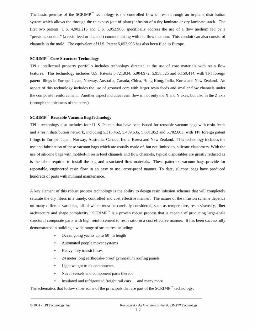
The basic premise of the SCRIMP™ technology is the controlled flow of resin through an in-plane distribution
system which allows the through the thickness (out of plane) infusion of a dry laminate or dry laminate stack. The
first two patents, U.S. 4,902,215 and U.S. 5,052,906, specifically address the use of a flow medium fed by a
“pervious conduit” (a resin feed or channel) communicating with the flow medium. This conduit can also consist of
channels in the mold. The equivalent of U.S. Patent 5,052,906 has also been filed in Europe.
SCRIMP™ Core Structure Technology
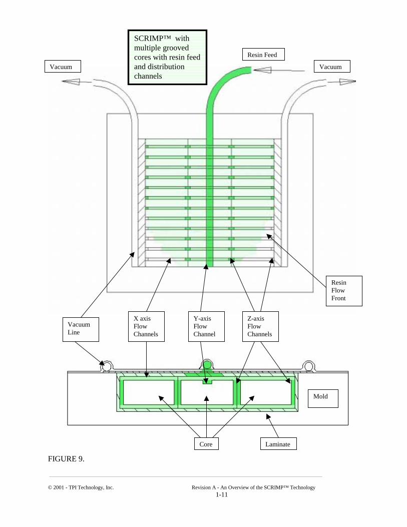
TPI’s intellectual property portfolio includes technology directed at the use of core materials with resin flow
features. This technology includes U.S. Patents 5,721,034, 5,904,972, 5,958,325 and 6,159,414, with TPI foreign
patent filings in Europe, Japan, Norway, Australia, Canada, China, Hong Kong, India, Korea and New Zealand. An
aspect of this technology includes the use of grooved core with larger resin feeds and smaller flow channels under
the composite reinforcement. Another aspect includes resin flow in not only the X and Y axes, but also in the Z axis
(through the thickness of the cores).
SCRIMP™ Reusable Vacuum BagTechnology
TPI’s technology also includes four U. S. Patents that have been issued for reusable vacuum bags with resin feeds
and a resin distribution network, including 5,316,462, 5,439,635, 5,601,852 and 5,702,663, with TPI foreign patent
filings in Europe, Japan, Norway, Australia, Canada, India, Korea and New Zealand. This technology includes the
use and fabrication of these vacuum bags which are usually made of, but not limited to, silicone elastomers. With the
use of silicone bags with molded-in resin feed channels and flow channels, typical disposables are greatly reduced as
is the labor required to install the bag and associated flow materials. These patterned vacuum bags provide for
repeatable, engineered resin flow in an easy to use, error-proof manner. To date, silicone bags have produced
hundreds of parts with minimal maintenance.
A key element of this robust process technology is the ability to design resin infusion schemes that will completely
saturate the dry fibers in a timely, controlled and cost effective manner. The nature of the infusion scheme depends
on many different variables, all of which must be carefully considered, such as temperature, resin viscosity, fiber
architecture and shape complexity. SCRIMP™ is a proven robust process that is capable of producing large-scale
structural composite parts with high reinforcement to resin ratio in a cost effective manner. It has been successfully
demonstrated in building a wide range of structures including:
• Ocean going yachts up to 60’ in length
• Automated people mover systems
• Heavy duty transit buses
• 24 meter long earthquake-proof gymnasium roofing panels
• Light weight truck components
• Naval vessels and component parts thereof
• Insulated and refrigerated freight rail cars … and many more…
The schematics that follow show some of the principals that are part of the SCRIMP™ technology.

© 2001 - TPI Technology, Inc.
Vacuum Line
FIGURE 1.
SCRIMP™ with feed line - Flow medium on top of laminate
Vacuum Line
Resin Flow Front
d
Feed Line
Revision A - An Overview of the SCRIMP™ Technology 1-3
Flow Medium
Vacuum
Flow Medium
Resin Fee
Laminate Resin FlowFront
Mold

© 2001 - TPI Technology, Inc. Revision A - An Overview of the SCRIMP™ T 1-4
FIGURE 2.
SCRIMP™ with feed line – with flow medium on top of laminate
Resin Feed Vacuum
Resin Flow Front
Resin Flow Front
Laminate
Resin Feed Line Flow Medium
Vacuum Line
Moldechnology

© 2001 - TPI Technology, Inc
FIGURE 3.
SCRIMPTM with resin feed in contact with flow medium d
Vacuum Line
Resin Fee
Vacuum. Revision A - An Overview of the SCRIMP™ Technology 1-5
d
Vacuum Line Flow
Medium
Vacuum
Resin Flow Front
Resin Fee
Resin Flow Front
Mold
Laminate
© 2001 - TPI Technology, Inc
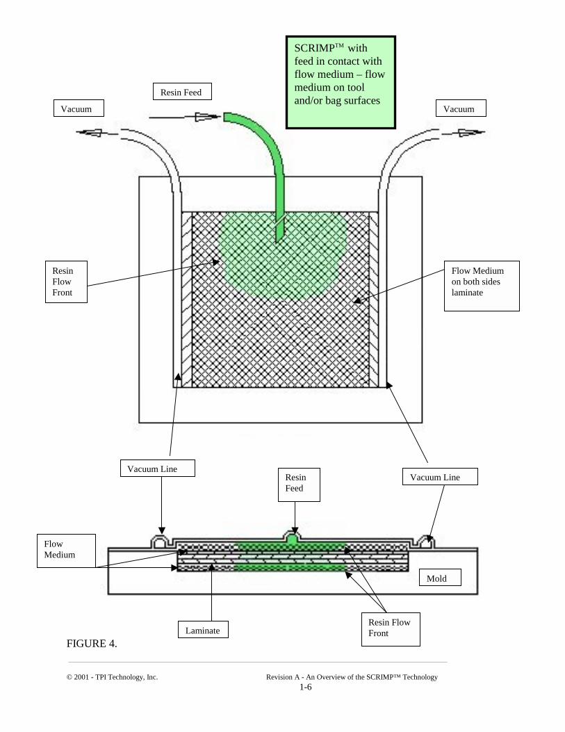
FIGURE 4.
SCRIMPTM with feed in contact with flow medium – flow medium on tool d
Flow Medium
Resin Flow Front
Resin Fee
. Revision A - An Overview of the SCRIMP™ Technology 1-6
and/or bag surfaces
Resin Feed
Resin Flow Front
Vacuum
VacuumFlow Medium on both sides laminate
Mold
Vacuum Line
Vacuum LineLaminate

© 2001 - TPI Technology, Inc. Revision A - An Overview of the SCRIMP™ Techn 1-7
FIGURE 5.
SCRIMPTM – flow medium inside laminate
Resin Feed
Resin Flow Front
Vacuum Line
Vacuum Line
Flow Medium
d
Resin Flow Front
Mold
Vacuum
olo
Vacuum
Resin Fee
gy
© 2001 - TPI Technology, Inc.
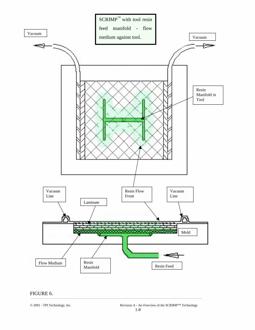
FIGURE 6.
Vacuum Line
Resin Manifol
SCRIMP™ with tool resin
feed manifold - flow
medium against tool.
Revision A - An Overview of the SCRIMP™ Techn 1-8
Vacuum Line
d d
Resin Flow Front
Vacuum
VacuumResin Manifold in Tool
Laminate
Resin Fee
Mold
Flow Medium
ology

© 2001 - TPI Technology, Inc. Re
FIGURE 7.
d
ResGro
Flow Medium
Flow Medium
SCRIMP™ with core and
flow medium - inserted into
tool
Resin Fee Vacuumvision A - An Overview of the SCRIMP™ Technology 1-9
in Feed ove
Resin Feed Groove
Vacuum
Vacuum Line Vacuum Line Mold Laminate
© 2001 - TPI Technology, Inc.
FIGURE 8.
SCRIMP™ grooved core with resin feed and distribution channels
Resin Feed Channel
Resin Distribution Channels Vacuum Line
d
CORE
Revision A - An Overview of the SCRIMP™ Techn 1-10
MoldVacuum Line
Resin Fee
Vacuum
olo
Vacuum
gy
© 2001 - TPI Technology, Inc.
FIGURE 9.
d
Vacuum Line
SCRIMP™ with multiple grooved cores with resin feedand distribution channels
Vacuum
Revision A - An Overvie 1-11
X axis Flow Channels
Y-axis Flow Channel
e
Resin Fee
w of the SCRIMP™ Technology
Z-axis Flow Channels
M
Vacuum
Resin Flow Front
old
Laminate
Cor
© 2001 - TPI Technology, Inc.
FIGURE 10.
Resin
Vacuum Tight Seal
VacuuLine
SCRIMP™ VacuumBag with resin feed and distribution channels
Revision A - An Overview of the SCRIMP™ Technology 1-12
Feed
m Resin Feed Channel
Resin Distribution Pattern
VaLin
Vacuum
Vacuumcuum e