An Overview of Ion Beam Driven HEDP Research Program …hifweb.lbl.gov/public/BeamHEDP2010/1....
40
An Overview of Ion Beam Driven HEDP Research Program at FAIR : The HEDgeHOB Collaboration Naeem A. Tahir a Gesellschaft für Schwerionenforschung Planckstrasse 1, 64291 Darmstadt e-mail: [email protected] Collaborators: A.R. Piriz b , A. Shutov c , I.V.Lomonosov c , V.E.Fortov c , P. Spiller a R.Redmer d , Th. Stölker a b UCLM, Ciudad Real,Spain; c IPCP, Chernogolovka,Russia; d Rostock University
Transcript of An Overview of Ion Beam Driven HEDP Research Program …hifweb.lbl.gov/public/BeamHEDP2010/1....

An Overview of Ion Beam Driven HEDP Research Program at FAIR : The HEDgeHOB Collaboration
Naeem A. TahiraGesellschaft für Schwerionenforschung Planckstrasse 1, 64291 Darmstadt email: [email protected]
Collaborators:A.R. Pirizb, A. Shutovc, I.V.Lomonosovc, V.E.Fortovc, P. Spillera
R.Redmerd, Th. Stölkera
bUCLM, Ciudad Real,Spain; cIPCP, Chernogolovka,Russia; dRostock University

Definition:States that correspond to an energy content of 1011 J/m3 or equivalently1 Mbar pressure [HED states].
Importance:Spans over wide areas of basic & applied physics. For example; astrophysics, planetary sciences, geophysics, inertial fusion, strongly coupled plasmas and many others.
In addition to that, HED matter has great potential for numerous lucrative industrial applications.
Region at the top and to the right of the brown line is HED matter.Region enclosed in purple circle isthe WDM .

Definition: WDM state of matter between a normal solid and an ideal plasma.
Standard theoretical techniques break down in this region.
Experiments are badly needed toinvestigate physical properties ofthe WDM region.
WDM occurs in cores of large planets and ICF plasmas.
R. More

The new synchrotron, SIS100 that will be built at the future FAIR [Facility for Antiprotons and Ion Research] facility, will deliver a uranium beam with three orders of magnitude higher intensity than what is currently available at the existing SIS18 synchrotron.
IntensityBunch LengthBeam EnergyParticle EnergyFWHMSpecific EnergyDeposition in PbSpecific PowerDeposition in Pb
SIS18 4x10⁹
130 ns 0.06 kJ
400 MeV/u1.0 mm
1 kJ/g
5 GW/g
SIS1005x1011
50 ns76 kJ
0.4 – 2.7 GeV/u1.0 mm
150 kJ/g
3 TW/g
[x 100]
[x 150]
[x 600]
SUMMARY OF PARAMETERS

Intense particle beams are a novel, very efficient tool to study HEDP and WDM [N.A. Tahir et al. PRE 60 (1999) 4715; PRE 61 (2000) 1975; PRE 62 (2000) 1224; PRE 63 (2001) 016402;PRE 63 (2001) 036407; PRB 67 (2003) 184101].
Main Advantages of this scheme are:● High repetition rate, high coupling efficiency● Large sample size● Fairly uniform physical conditions (no sharp gradients)● Precise knowledge of energy deposition in the sample● Long life times ● Any target material can be used

200 MeV/u U IonsN = 2x1011
= 50 nsFWHM = 1 mmLead CylinderL = 4 mmr = 3 mm
N.A.Tahir, PRE 61 (2000) 1975


3. LAPLAS [LAboratory PLAnetary Sciences] Experimental Scheme:
Lowentropy compression of a test material like H or H2O, in a multlayered
cylindrical target [Hydrogen Metallization , Planetary Interiors] N.A. Tahir et al., PRE 64 (2001) 016202; High Energy Density Phsics 2 (2006) 21;
A.R. Piriz et al, PRE 66 (2002) 056403.
● Shock reverberates between the cylinder axis and the hydrogenouter shell interface.
● Very high (23 g/cc), ultra high P (30 Mbar) , low T (of the order of 10 kK).
Hollow BeamCircular beam
● Very high densities, high pressure, higher temperature = 1.2 g/cc, P = 11 Mbar, T = 5 ev
Au or Pb

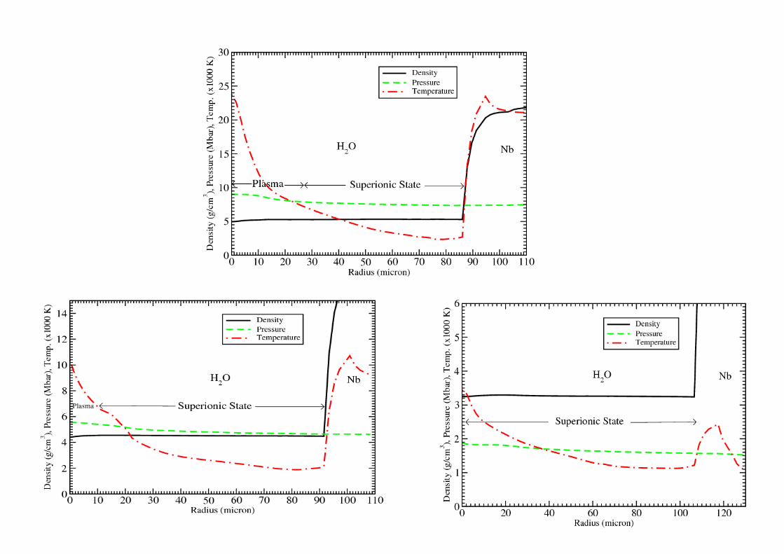
Phase Diagram of Water [QMD Simulations]
Mattsson & Desjarlais, PRL 97 (2006) 017801 M. French et al., PRB 79 (2009) 054107

Hollow Beam
1.5 GeV/u U ions = 50 ns
Sample : WaterOuter Shell: W & Nb
Ri = 0.2 mm
R1 = 0.4 mm
R2 = 1.4 mm
Ro = 3.0 mm
L = 7.0 mm
N.A. Tahir et al., “Ultra High Compressionof Water and Application to Planetary Physics” (2010) In Press.


= 50 ns, R1 = 0.4 mm, R
2 = 1.2 mm
N = 5x10¹¹, 3x10¹¹ and 1011

Circular Beam
FWHM = 1.5 mm
N = 5x10¹¹, 3x10¹¹, 1011


4. HIHEX [Heavy Ion Heating and Expansion
This technique involves isochoric and uniform heating of matter by an intense ion beam and the heated materialis allowed to expand isentropically.
Expanded Hot LiquidTwoPhase LiquidGas RegionCritical ParametersStrongly Coupled Plasma
References:1) D.H.H. Hoffmann et al., Phys. Plasmas 9 (2002) 3651.2) N.A. Tahir et al., Phys. Rev. Lett. 95 (2005) 035001.

Phase diagram of lead

Critical Parameters of Some Metals
I.V. Lomonosov and V.E. Fortov
Tc (K) P
c(kbar) ρ
c(g/cm3)
Aluminum 6390 4.45 0.86 Copper 7800 9.00 2.28 Gold 8500 6.14 6.10 Lead 5500 2.30 3.10 Niobium 19200 11.1 1.70Tantalum 14550 7.95 3.85Tungsten 13500 3.10 2.17Beryllium 8600 2.00 0.40

Cylindrical HIHEX Experiment Design Using Solid Material

Numerical Simulation Results:
Target Parameters: Solid lead cylinder, L = 2 3 mm, r = 300 500 m
Beam Parameters:Uranium BeamParticle Energy = 1 GeV/uBeam Intensity = 1010 – 1011 ions / bunchBunch Length = 50 ns
Early and Intermediate Stages of FAIR

Simulation Results from a Typical Case
● Solid Lead Cylinder
● L = 2 mm, r = 300 m
● N = 2.5 x10¹⁰
● Bunch Length = 50 ns
● Beam spot Size (FWHM) = 2 mm
N.A. Tahir et al., Phys. Rev. Lett. 95 (2005) 035001
/g
/g

SCP : strongly coupled plasmas CP : critical point2PLG: twophase liquidgasEHL : expanded hot liquidG : Gas

HIHEX Using Porous Material N.A. Tahir et al., High Energy Density Phys. 2 (2006) 21.

1 GeV/u uranium beam
N = 5x10¹¹ , τ = 50 ns
FWHM = 4 mm
Es = 5.5 kJ/g
FWHM = 2 - 4 mm
N = 1011 – 5x10¹¹
Γ = 5

HEDgeHOB [High Energy Density Matter Generated by Heavy Ion Beams]
HIHEX [Heavy Ion Heating and Expansion]
LAPLAS [Laboratory Planetary Science]
Ramp CompressionRichtmyerMeshkov Instability Growth Studies

CONCLUSIONS:
1. 1.
1. An intense heavy ion beam is a very efficient tool to induce HED states in matter; large sample size, week gradients, long life times.
2. Construction of the future FAIR facility at Darmstadt will enable one to carry out novel and unique experiments in this filed.
3. Theoretical studies (simulations + analytic modeling) has shown that an intense heavy ion beam can be employed using four very different schemes to study HED physics.
A). HIHEX [Heavy Ion Heating and Expansion] One can use solid as well as porous targets; all interesting physical state, EHL, 2PLG, CP, SCP can be accessed using the beam at the FAIR facility. B). LAPLAS [LAboratory PLAnetary Sciences] The scheme is robust, insensitive to large variations in beam and target parameters, hydrodynamically stable (RayleighTaylor and RichtmeyerMeshkov). C). Ramp Compression: Studies of Material properties under dynamic conditions D) . RichtmyerMeshkov Instability Growth Studies
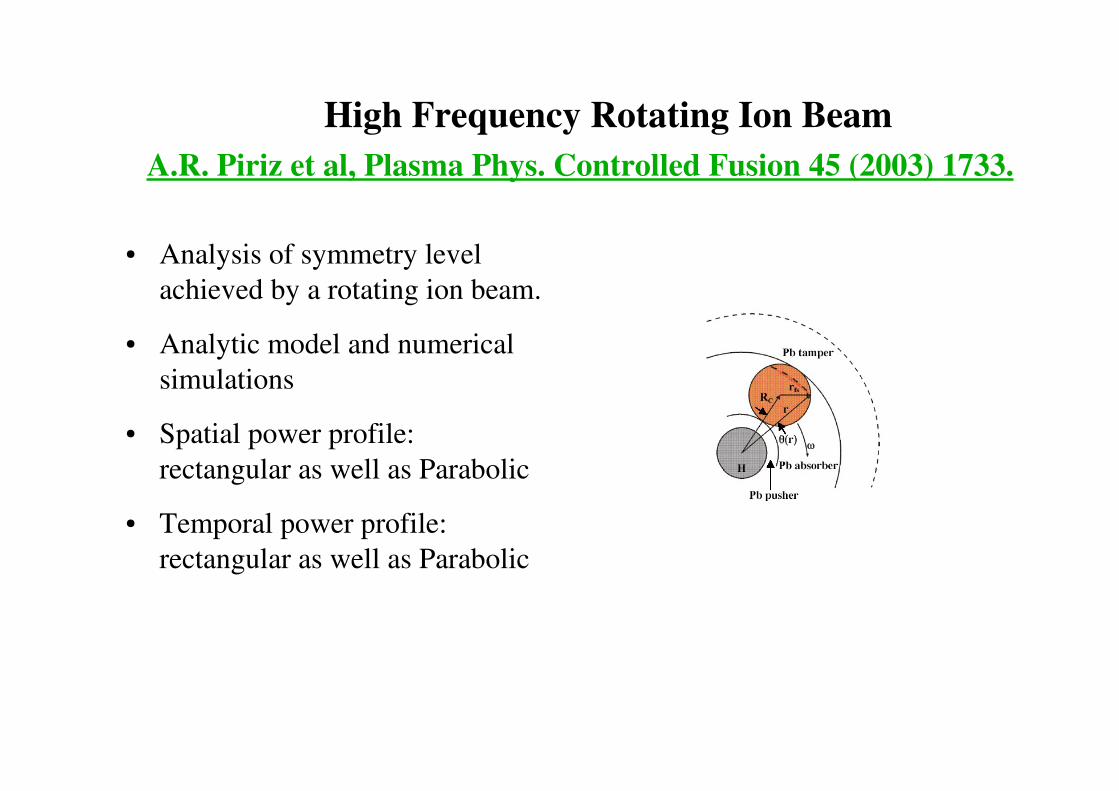
High Frequency Rotating Ion Beam A.R. Piriz et al, Plasma Phys. Controlled Fusion 45 (2003) 1733.
● Analysis of symmetry level achieved by a rotating ion beam.
● Analytic model and numerical simulations
● Spatial power profile: rectangular as well as Parabolic
● Temporal power profile: rectangular as well as Parabolic

Power Constant in Time● Circular shape of the focal spot
introduces radial distribution in the energy deposition.
● For both cases, the relative pressure asymmetry:
∆P/P~1/N ● N = ω τ where ω = 2πν
● For τ = 50 ns, one would require an ω = 2 GHz to achieve 1 % asymmetry.

For achieving 1 % asymmetry
1. With uniform temporal profile one needs N = 100. For τ = 50 ns one need ω = 2 GHz
2. With parabolic temporal profile one needs N = 10. For τ = 50 ns one need ω = 0.2 GHz
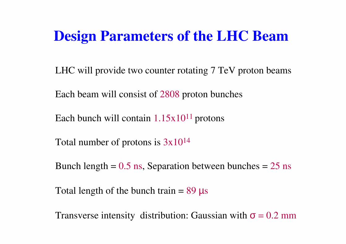
Design Parameters of the LHC Beam
LHC will provide two counter rotating 7 TeV proton beams
Each beam will consist of 2808 proton bunches
Each bunch will contain 1.15x10¹¹ protons
Total number of protons is 3x10¹⁴
Bunch length = 0.5 ns, Separation between bunches = 25 ns
Total length of the bunch train = 89 µs
Transverse intensity distribution: Gaussian with σ = 0.2 mm

First Step: Energy loss of 7 TeV protons in solid copper target is calculated using the FLUKA Code
Target Geometry:● Solid Cu Cylinder L = 5 m, r = 1 m ● Peak energy deposition 1200 GeV/proton/cm3
Second Step: This energy loss data is converted into kJ/g and is used as input to a 2D hydrodynamic computer code, BIG2.

Specific Energy Deposition by a Single Bunch in Solid Copper [FLUKA Calculations]
● Specific energy (kJ/g) deposited by one bunch of protons along L at r = 0.
● Maximum deposition of about 2.3 kJ/g occurs at L ~ 16 cm.

Specific Energy Deposition in Radial Direction Along the Target Axis
Specific energy deposition (kJ/g) vs radius at, L = 8 cm, 16 cm, 24 cm and 36 cm, by a single proton bunch.

Target Parameters
[N.A. Tahir et al., J. Appl. Phys. 97 (2005) 135004; PRL 94 (2005) 083532; Phys. News Update No: 726#3, APS News February 2006, PRE 79 (2009) 046410, Laser Part. beams 27 (2009) 475.]
Solid copper target facially irradiated by the LHC beam
L = 5 m, r = 5 cm
● The target is studied in rZ geometry● Specific energy deposition in each simulation cell at every timestep is normalized with respect to the line density along the axis. ● This allows for reduction of specific energy deposition in low density part of the target.● This model allows for studying the proton “Tunneling Effect”.

Specific Energy Deposition
Saturates to 25 kJ/g
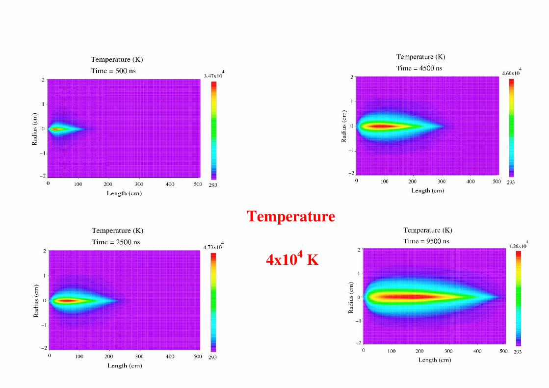
Temperature
4x10⁴ K

Pressure
30 GPa

HEDP States

0.35 m/s in 89 s penetrate 35 m