An optimized path-selection using airtime metric in OLSR networks
107
UNIVERSITY OF OSLO Department of informatics Metric-based routing framework and radio- aware shortest path selection for OLSR Design, implementation and testing Thomas Aure UniK University Graduate Center University of Oslo [email protected]
-
Upload
thomas-aure -
Category
Technology
-
view
25 -
download
0
Transcript of An optimized path-selection using airtime metric in OLSR networks

UNIVERSITY OF OSLO Department of informatics
Metric-based routing
framework and radio-
aware shortest path
selection for OLSR
Design, implementation
and testing
Thomas Aure UniK University Graduate Center University of Oslo [email protected]

Part I – Contents
Page 2/107
Preface This thesis is written at UniK University Graduation Center, as a part of my Master degree in Computer Science at the University of Oslo, Department of Informatics. Designing improvements and implementing these enhancements for an already existing routing protocol is a big challenge to take on, but it is also very encouraging to see how the changes actually work in real-life scenarios, instead of by observing these modifications using simulations only. It has been very interesting to learn about the detailed inner operations of a routing protocol, and I have learned a lot about network programming on the Linux platform. In my work with this thesis we came up with new and interesting angles to approach the investigated problems, and I was basically allowed to design most aspects of this thesis by myself, but under the guidance of Frank Y. Li, for that I would like to thank him. Thomas Aure,
Oslo, May 2nd 2008

Part I – Contents
Page 3/107
Abstract Ad-hoc and MESH networks have been a topic for research in the last few years. It is now starting to be mature and we do see implementations in the various areas of interest. One important research area in MANETs is routing. There is no doubt that routing in MANETs is a challenging task, and has therefore received tremendous amount of attention from researchers all over the world. This has led to the development of many different routing protocols for the MANET, approaching the common challenges in different ways. These routing protocols are normally categorized as either re-active, pro-active or hybrid protocols. One of the pro-active routing protocols commonly used in a MANET is the Optimized Link State Routing Protocol (OLSR). OLSR is a routing protocol originally designed for mobile ad hoc networks, and has been standardized and implemented. However, the current standard needs to be enhanced in order to meet requirements for multi-homing, metric retrieval, metric-based routing and path calculation in a network with global Internet connectivity. The work presented in this thesis is targeted at making specific improvement to OLSR, based on the existing UniK OLSRd implementation. These enhancements include a metric-based
framework, a new radio-aware airtime metric and finally a multi-homing solution with load-
balancing. The foundation for the two last mentioned improvements is the metric-based framework. The requirements for these improvements were initiated during the EU-project referenced in the list of publications. The enhancements that are designed, implemented and tested in this thesis, provide OLSR with improved capability to carry generic metric information in control messages. In addition they also make it possible to retrieve and use the airtime cross-layer metric for path calculation. Finally, the tests performed in a Linux based test environment consisting of several laptops with the OLSR enhancements implemented in this thesis, show that there is an improvement in path selection when the radio aware airtime metric is used. Instead of always selecting the path with the lowest hop count, a better path with lower airtime cost which considers both errors, speed and transmission data rates will be selected. As a result, better network utilization with less path congestion has been achieved.

Part I – Contents
Page 4/107
List of publications
1. F. Pagliazzo, L. Vandoni, G. Zicca, G. M. Giani, M. Giulini, S. Zanoli, M. Mihaljevic, F.
Y. Li, G. Egeland, T. Aure, O. Lazaro, P. Sanchez, M. Ravalli, and P. Bucciol, "Software Implementation (final version)", ADHOCSYS project, Deliverable D16, FP6 IST-2004-026548, delivered to the European Commission, May 2007.
2. T. Aure and F. Y. Li, "Load-balancing in Multi-homed OLSR Networks using Airtime
Metric and Radio-aware Path Selection: Design and implementation", 4th IEEE International Workshop on Heterogeneous Multi-hop Wireless and Mobile Networks 2008 (IEEE MHWMN’08), Atlanta, Georgia, September 29-October 2, 2008, Submitted.

Part I – Contents
Page 5/107
Contents
PREFACE........................................................................................................................... II
ABSTRACT....................................................................................................................... III
LIST OF PUBLICATIONS ...................................................................................................................................... IV LIST OF FIGURES................................................................................................................................................ IX LIST OF TABLES ...................................................................................................................................................X
PART II
1 INTRODUCTION ......................................................................................................11
1.1 THESIS OVERVIEW ...............................................................................................................................11 1.2 SOURCE CODE PRESENTATION.............................................................................................................11
2 MOBILE AD-HOC MESH AND OLSR NETWORKS ............................................12
2.1 INTRODUCTION ....................................................................................................................................12 2.2 AN OVERVIEW OF MANET/MESH ROUTING PROTOCOLS.....................................................................12 2.3 OLSRV1 BASICS .................................................................................................................................13
2.3.1 OLSR Packet Formats....................................................................................................................13 2.3.2 Neighbor discovery ........................................................................................................................15 2.3.3 Topology discovery ........................................................................................................................15 2.3.4 Multipoint Relays (MPRs) ..............................................................................................................15 2.3.5 Route Calculation...........................................................................................................................16 2.3.6 Connectivity to non-OLSR domain.................................................................................................16
2.4 OLSR VERSION 2 DRAFT.....................................................................................................................17 2.4.1 OLSRv2 Link Metrics .....................................................................................................................17
2.5 DYMO ................................................................................................................................................18 2.6 IEEE 802.11S ......................................................................................................................................18
2.6.1 Mesh Points / Mesh Access points..................................................................................................18 2.6.2 HWMP............................................................................................................................................20 2.6.3 RA-OLSR........................................................................................................................................20
2.7 802.11 STANDARDS .............................................................................................................................21 2.7.1 802.11b...........................................................................................................................................21 2.7.2 802.11a...........................................................................................................................................21 2.7.3 802.11g...........................................................................................................................................22 2.7.4 802.11n...........................................................................................................................................22
2.8 THE WIRELESS EXTENSIONS (WE) API...............................................................................................23
3 OVERVIEW OF THE UNIK OLSRD.......................................................................24
3.1 INTRODUCTION ....................................................................................................................................24 3.2 PARSERS ..............................................................................................................................................25
3.2.1 The packet parser ...........................................................................................................................25 3.2.2 The socket parser ...........................................................................................................................25
3.3 INFORMATION REPOSITORIES ...............................................................................................................25 3.3.1 Link Set...........................................................................................................................................26 3.3.2 Neighbor Set / 2 Hop Neighbor Set ................................................................................................26 3.3.3 MPR Set / MPR Selector set ...........................................................................................................27 3.3.4 Topology Information Base ............................................................................................................27

Part I – Contents
Page 6/107
3.3.5 Host and Network Association (HNA) Set......................................................................................27 3.4 LINK QUALITY EXTENSION ..................................................................................................................28
3.4.1 Dijkstras algorithm for finding the shortest path ...........................................................................28 3.5 PLUG-IN ARCHITECTURE ......................................................................................................................29
PART III
4 MF-OLSR DESIGN OVERVIEW.............................................................................30
4.1 AN OVERVIEW OF THE IMPLEMENTED IMPROVEMENTS IN MF-OLSR ..................................................32 4.2 MF-OLSR W/AIRTIME PLUG-IN EXAMPLE ...........................................................................................33 4.3 OVERVIEW OF LINK METRIC TYPES AND LINK METRIC VALUES .........................................................35 4.4 OVERVIEW OF MF-HELLO MESSAGING..............................................................................................36
4.4.1 The MF-HELLO message packet format........................................................................................36 4.4.2 Link Sensing and Neighbor discovery using MF-HELLO..............................................................36
4.5 OVERVIEW OF MF-TC MESSAGING......................................................................................................38 4.5.1 The MF-TC message packet format ...............................................................................................38 4.5.2 Topology generation using MF-TC messages ................................................................................38
4.6 OVERVIEW OF MF-HNA MESSAGING ..................................................................................................39 4.6.1 The MF-HNA message packet format ............................................................................................39 4.6.2 Dissemination of MF-HNA messages.............................................................................................40
4.7 OVERVIEW OF THE MAC ADDRESS BASED LOCAL ASSOCIATION BASE (LAB)....................................41
5 MF-OLSR PLUG-INS DESIGN OVERVIEW..........................................................42
5.1 OVERVIEW OF THE AIRTIME PLUG-IN ..................................................................................................42 5.1.1 Airtime metric calculation..............................................................................................................43
5.2 OVERVIEW OF THE MULTIHOMING PLUG-IN ........................................................................................44 5.2.1 Introduction to MF-HNA messaging..............................................................................................44 5.2.2 Current problem with hop count multihoming ...............................................................................44 5.2.3 Example scenario using the extended HNA messages....................................................................45
5.3 OVERVIEW OF THE HTTPINFO+ PLUG-IN ..............................................................................................46
PART IV
6 MF-OLSR IMPLEMENTATION DETAILS............................................................48
6.1 MF-OLSR FILES ..................................................................................................................................48 6.2 REGISTRATION OF THE PACKET GENERATION METHODS ......................................................................50 6.3 REGISTRATION OF THE PACKET PARSER METHODS ...............................................................................50 6.4 IMPLEMENTATION OF MF-HELLO MESSAGING...................................................................................51
6.4.1 The MF-HELLO message packet format and memory structure....................................................51 6.4.2 Building and serializing MF-HELLO messages.............................................................................53 6.4.3 Receiving and processing MF-HELLO messages ..........................................................................54 6.4.4 The Local Link Set..........................................................................................................................55
6.5 IMPLEMENTATION OF MF-TC MESSAGING...........................................................................................56 6.5.1 MF-TC message packet format and memory structure ..................................................................56 6.5.2 Building and serializing the MF-TC message ................................................................................58 6.5.3 Receiving and processing MF-TC message ...................................................................................59 6.5.4 Modifications to the Topology Information Base (TIB) .................................................................59 6.5.5 Modifications to the Topology Information Base memory structures ............................................60
6.6 IMPLEMENTATION OF MF-HNA MESSAGING .......................................................................................61 6.6.1 MF-HNA message packet format and memory structure ...............................................................61 6.6.2 Modifications to the local HNA set ................................................................................................62 6.6.3 Building and serializing HNA messages ........................................................................................63

Part I – Contents
Page 7/107
6.6.4 Receiving and processing MF-HNA messages...............................................................................64 6.6.5 Route re-calculation trigger for HNA routes .................................................................................64
6.7 PRINTING AND DEBUG METHODS..........................................................................................................65
7 THE MULTIHOME PLUG-IN..................................................................................66
7.1 MULTIHOMING PLUG-IN FILES AND CONFIGURATION ...........................................................................66 7.1.1 Multihoming plug-in configuration ................................................................................................66
7.2 DISSEMINATION OF MULTI-HOMING HNA MESSAGES ..........................................................................66 7.2.1 Multihoming gateway metrics ........................................................................................................67
7.3 GATEWAY STATUS DISCOVERY ............................................................................................................67
8 THE AIRTIME PLUG-IN..........................................................................................69
8.1 OPERATIONAL OVERVIEW ...................................................................................................................69 8.2 IMPLEMENTATION OVERVIEW .............................................................................................................70
8.2.1 Airtime plug-in files........................................................................................................................71 8.2.2 Airtime plug-in configuration parameters......................................................................................71
8.3 RETRIEVING LOWER LAYER INFORMATION ..........................................................................................71 8.3.1 Using the Wireless Extensions API to retrieve information ...........................................................72 8.3.2 ARP query for IP to MAC address resolution ................................................................................73 8.3.3 Local Link State Discovery phase ..................................................................................................74
8.4 AIRTIME METRIC CALCULATION ..........................................................................................................75 8.4.1 Airtime Metric Parameters.............................................................................................................75 8.4.2 Link Quality as error probability ...................................................................................................75
8.5 LOCAL ASSOCIATION BASE (LAB) ......................................................................................................76 8.5.1 The LAB entry ................................................................................................................................76 8.5.2 LAB Set implementation .................................................................................................................77
PART V
9 TESTS AND RESULTS .............................................................................................78
9.1 TESTBED EQUIPMENT...........................................................................................................................78 9.2 TESTS AND OBSERVED RESULTS...........................................................................................................78
9.2.1 Basic functionality testing / proof-of-concept ................................................................................78 9.2.2 Proximity based convergence testing scenario ..............................................................................80 9.2.3 Load-based convergence testing scenario......................................................................................81
9.3 PARAMETER OPTIMIZATION FOR TRIGGERING OF ROUTE RE-CALCULATION .........................................82 9.4 FUNCTIONALITY TESTING USING OLSR_SWITCH...................................................................................82
10 CONCLUSIONS AND FUTURE WORK .................................................................84
10.1 CONCLUSIONS......................................................................................................................................84 10.2 MAJOR CONTRIBUTIONS OF THIS THESIS ..............................................................................................85 10.3 FUTURE WORK ....................................................................................................................................86
REFERENCES...................................................................................................................87
INDEX ................................................................................................................................89

Part I – Contents
Page 8/107
APPENDICES
APPENDIX A – COMPILATION AND USAGE INFORMATION................................90
APPENDIX B – CODE NUGGETS...................................................................................94
APPENDIX C – HOW TO MODIFY OLSRD CONFIGURATION FILE OPTIONS ...96
APPENDIX D – ADDITIONAL SOFTWARE DETAILS ...............................................99
APPENDIX E – DELIVERABLE D16 ADHOCSYS (FRONTPAGE ONLY)..............101
APPENDIX F – PAPER – LOAD-BALANCING IN MULTI-HOMED OLSR
NETWORKS ....................................................................................................................103

Part I – Contents
Page 9/107
List of figures
FIGURE 2.1 – AN OVERVIEW OF HOW TWO ADJACENT NODES ESTABLISH THE NEIGHBORSHIP USING HELLO
MESSAGES .....................................................................................................................................................15 FIGURE 2.2 - AN MPR OPTIMIZED MANET USING OLSR ......................................................................................16 FIGURE 2.3 - AN EXAMPLE MESH NETWORK WITH MESH NODES AND MESH ACCESS POINTS (MAP) ..................19 FIGURE 3.1 - THE OLSRD MODULAR DESIGN OVERVIEW ........................................................................................24 FIGURE 3.2 - AN OVERVIEW OF THE OLSRD MESSAGE TYPES AND REPOSITORIES ..................................................25 FIGURE 3.3 – THE RELATIONSHIP BETWEEN LQ AND HELLO MESSAGES ...............................................................28 FIGURE 4.1 - A SCHEMATIC OVERVIEW OF THE MF-OLSR DAEMON AND THE AIRTIME PLUG-IN ............................30 FIGURE 4.2 – AN EXAMPLE MANET RUNNING MF-OLSR WHERE AIRTIME METRIC SHORTEST PATH HAS BEEN
CALCULATED AND A PATH FROM C TO E IS SELECTED ...................................................................................33 FIGURE 4.3 - NEIGHBOR DISCOVERY PROCESS ........................................................................................................37 FIGURE 5.1 – A SCHEMATIC OVERVIEW OF THE AIRTIME PLUG-IN DESIGN..............................................................42 FIGURE 5.2 - SIMPLIFIED FORMULA FOR CALCULATING AIRTIME METRIC ...............................................................43 FIGURE 5.3 – AN ILLUSTRATION OF THE PROBLEM WITH HNA HOP COUNT METRIC SELECTION .............................44 FIGURE 5.4 – AN IMPROVED PATH SELECTION IN MULTIHOMED NETWORKS USING MF-HNA MESSAGES ...............45 FIGURE 5.5 – A SNAPSHOT OF THE HTTPINFO+ CONFIGURATION WEB INTERFACE ..................................................46 FIGURE 5.6 - HTTPINFO+ LOCAL ASSOCIATION BASE WEB INTERFACE ..................................................................47 FIGURE 5.7 - HTTPINFO+ AIRTIME WEB INTERFACE ...............................................................................................47 FIGURE 6.1 - MF-OLSR SOURCE CODE FILE STRUCTURE LAYOUT ..........................................................................49 FIGURE 6.2 – THE RELATIONSHIP BETWEEN THE MF-HELLO MESSAGE DESERIALIZED STRUCTURES ....................52 FIGURE 6.3 – AN OVERVIEW OF THE MF-HELLO MESSAGE GENERATION PROCESS ...............................................53 FIGURE 6.4 – AN OVERVIEW OF THE MF-HELLO MESSAGE HANDLING PROCESS ...................................................54 FIGURE 6.5 - EXAMPLE ATTRIBUTES OF THE LINK_ENTRY STRUCTURE ...................................................................55 FIGURE 6.6 – THE RELATIONSHIP BETWEEN THE MF-TC MESSAGE DESERIALIZED STRUCTURES ............................57 FIGURE 6.7 – AN OVERVIEW OF THE MF-TC MESSAGE GENERATION PROCESS .......................................................58 FIGURE 6.8 – AN OVERVIEW OF THE MF-TC MESSAGE HANDLING PROCESS...........................................................59 FIGURE 6.9 – AN OVERVIEW OF THE HNA MESSAGE GENERATION PROCESS...........................................................63 FIGURE 6.10 - HNA MESSAGING OVERVIEW ...........................................................................................................64 FIGURE 8.1 - OVERVIEW OF HOW THE AIRTIME PLUG-IN RETRIEVES LOWER LAYER INFORMATION AND CONVERTS
THIS TO METRIC INFORMATION. .....................................................................................................................69 FIGURE 8.2 - A FLOW DIAGRAM OF HOW THE MOST IMPORTANT AIRTIME PLUG-IN METHODS ARE EXECUTED ........70 FIGURE 8.3 – AN OVERVIEW OF THE ARP CACHE QUERY SOLUTION ......................................................................73 FIGURE 9.1 - NETWORK LAYOUT FOR THE BASIC FUNCTIONALITY TESTING ............................................................79 FIGURE 9.2 - NETWORK LAYOUT FOR TESTING PROXIMITY BASED ROUTE RE-CALCULATION FOR MOBILE NODES ..80 FIGURE 9.3 - NETWORK LAYOUT FOR TESTING ROUTE RE-CALCULATION ON NETWORK CONGESTION / LOAD.........81 FIGURE 9.4 – MF-OLSR RUNNING IN 10 NODE OLSR_SWITCH MF-OLSR NETWORK 1/2.......................................82 FIGURE 9.5 – MF-OLSR RUNNING IN 10 NODE OLSR_SWITCH MF-OLSR NETWORK 2/2.......................................83

Part I – Contents
Page 10/107
List of tables
TABLE 2-1 - THE GENERIC OLSR PACKET FORMAT ...............................................................................................13 TABLE 2-2 – HELLO MESSAGE PACKET FORMAT AS DESCRIBED IN RFC3626........................................................13 TABLE 2-3 – TC MESSAGE PACKET FORMAT AS DESCRIBED IN RFC3626................................................................14 TABLE 2-4 – MID MESSAGE PACKET FORMAT AS DESCRIBED IN RFC3626.............................................................14 TABLE 2-5 – HNA MESSAGE PACKET FORMAT AS DESCRIBED IN RFC3626 ............................................................14 TABLE 2-6 - AN OVERVIEW OF THE 802.11 WIRELESS STANDARDS .........................................................................21 TABLE 4-1 – MF-OLSR EXAMPLE: NODES RADIO TYPE .........................................................................................33 TABLE 4-2 – MF-OLSR EXAMPLE: BIT RATE .........................................................................................................34 TABLE 4-3 - MF-OLSR EXAMPLE: ERROR PROBABILITY ........................................................................................34 TABLE 4-4 – THE CONSTANT VALUES DEFINED FOR THE VARIOUS LINK METRIC TYPES LIKELY TO BE USED IN
METRIC OPERATIONS (ONLY SOME OF THEM USED IN THIS IMPLEMENTATION)...............................................35 TABLE 4-5 – THE DEFINED LINK METRIC VALUE BOUNDS AND DEFAULT VALUES .................................................35 TABLE 4-6 – MF-HELLO MESSAGE WITH TWO NEIGHBORS CARRYING TWO METRICS EACH ..................................36 TABLE 4-7 – MF-TC MESSAGE PACKET FORMAT WITH TWO NEIGHBORS ................................................................38 TABLE 4-8 - EXTENDED HNA MESSAGE PACKET FORMAT ......................................................................................39 TABLE 5-1 - AIRTIME COST CONSTANT VALUES .....................................................................................................43 TABLE 5-2 - AIRTIME COST DYNAMIC VALUES.......................................................................................................43 TABLE 6-1 - ADDITIONAL FILES INCLUDED FOR MF-OLSR ....................................................................................48 TABLE 6-2 – TABLE CONTAINING THE ATTRIBUTES IN THE TOPOLOGY INFORMATION BASE
(TC_TABLE[HASHSIZE]) .............................................................................................................................59 TABLE 7-1 - THE LIST OF PREDEFINED GATEWAY METRIC TYPES FOR THE MULTIHOMING PLUG-IN .......................67 TABLE 8-1 - LIST OF FILES INCLUDED IN THE AIRTIME PLUG-IN ..............................................................................71 TABLE 8-2 - LAB SET EXAMPLE.............................................................................................................................77

Part II – Introduction, theory and background
Part II – Introduction, theory and background Page 11/107
Part II - Background
1 Introduction An introduction to the research area and related technologies and implementations are covered in this part of the thesis. If you are familiar with the OLSR protocol and the UniK OLSRd implementation, Chapters 2 and 3 can be skipped.
1.1 Thesis Overview
The rest of this thesis mainly consists of the parts described below.
• Part II - Introduction, theory and background (Chapter 1-3) o Contains the introduction of the research area, MANET/MESH introduction,
and some background information on UniK OLSRd.
• Part III - Design (Chapters 4-5) o Contains the design overview, tests/results and conclusions.
• Part IV - Implementation (Chapters 6-8) o Contains the MF-OLSR implementation details.
• Part V – Tests and conclusions (Chapters 9-10)
• Appendices o Contains six appendices with more details on various aspects of this thesis.
Recommended reading:
Generic: An overview of the research area and this thesis can be gained by reading Part II, Part III and Part V. This will give a good understanding of the major contributions in this thesis without diving into the detailed programming stuff. Users: Users that would like to install and test MF-OLSR should also read the installation/usage instructions in the appendix. Developers: Developer details can be found in Part IV of this thesis.
1.2 Source Code Presentation
The source code presented in this thesis is presented using a consistent layout.
Source code is formatted and presented as Courier New 10 (normally
intended).

Part II – Introduction, theory and background
Part II – Introduction, theory and background Page 12/107
2 Mobile Ad-hoc Mesh and OLSR networks
2.1 Introduction
MANET stands for "Mobile Ad Hoc Network." A MANET is a type of ad-hoc network that can change locations and configure itself automatically. Because MANETS are mobile, they use wireless connections to connect to various networks. This can be a standard 802.11 wireless connection, or another medium, such as a cellular or satellite transmission. Over the past years the developments on routing protocols for MANET has been tremendous. There are now a very high number of routing protocols implemented, but there is still not a single protocol that has been recognized by the community as the protocol to use in all types of MANETs or MESH networks. Several proactive [1], [2] and reactive [3] routing protocols have been proposed. The common denominator is that most of them typically use the minimum hop-count metric.
2.2 An overview of MANET/Mesh routing protocols
Some of the most important routing protocols in MANET/Mesh networking research area are listed below.
• OLSRv1 (RFC3626) [1]
• OLSR version 2 (currently only draft) [4]
• AODV (Ad-hoc On-demand Distance Vector) (RFC3561) [5]
• DYMO (Dynamic MANET On-demand) [6]
• RA-OLSR (removed from 802.11s, but have interesting features) [7]
• HWMP (802.11s) (Hybrid Wireless Mesh Protocol) [8]
• …and many more.
There are several extensive lists of various routing protocols for ad-hoc networks. These usually contains different specifications and proposed implementations, one such unofficial list can be find in [9]. In the following chapters we will look at a couple of routing protocols related to this implementation in more detail.

Part II – Introduction, theory and background
Part II – Introduction, theory and background Page 13/107
2.3 OLSRv1 Basics
Optimized Link State Routing is one of several routing algorithms used in Mobile Ad-hoc networks and it is one of the most commonly implemented.
• Adaptive pro-active routing protocol
• A link state routing protocol creates a “network map” at each location. OLSR is specifically written for mobile ad-hoc networks. It is a table driven, proactive, routing protocol that exchanges link state information with other nodes on a regular basis. Topology information is diffused using topology control (TC) messages and neighbors are signaled using HELLO messages. To optimize the flow of control information only specific nodes called MPRs are elected to forward this type of information. The MPRs will be elected among the one hop neighbors such that they cover all the two hop neighbors. Finally a shortest path algorithm is executed on specific tables to calculate the path with the lowest hop count. OLSR according to the RFC makes no assumptions about the underlying link-layer.
2.3.1 OLSR Packet Formats
All traffic in OLSR is sent as different OLSR control packets on UDP port 698. These packets generally consist of an OLSR header and a body containing one or more OLSR messages. The message types in the basic OLSR definition are HELLO and TC messages. 0 1 2 3
0 1 2 3 4 5 6 7 8 9 0 1 2 3 4 5 6 7 8 9 0 1 2 3 4 5 6 7 8 9 0 1
Packet Length (16 bit) Packet Sequence Number (16 bit)
Message Type (8 bit) Vtime (8 bit) Message Size
Originator Address (32 bit)
Time To Live (8 bit) Hop Count (8 bit) Message Sequence Number
MESSAGE
Table 2-1 - The generic OLSR Packet Format
From Table 2-1 we see that the OLSR header contains 16 bytes. The rest of the packet, the OLSR body, can contain one or several OLSR messages. The OLSR messages that are normally diffused using OLSR messages are HELLO,TC, MID and HNA messages. The formats of each of these are described in this chapter, starting with the HELLO message packet format. 0 1 2 3
0 1 2 3 4 5 6 7 8 9 0 1 2 3 4 5 6 7 8 9 0 1 2 3 4 5 6 7 8 9 0 1
Reserved Htime Willingness
Link Code Reserved Link Message Size (16)
Neighbor Interface Address
Table 2-2 – HELLO message packet format as described in RFC3626

Part II – Introduction, theory and background
Part II – Introduction, theory and background Page 14/107
The HELLO message can include several neighbors in each message. 0 1 2 3
0 1 2 3 4 5 6 7 8 9 0 1 2 3 4 5 6 7 8 9 0 1 2 3 4 5 6 7 8 9 0 1
ANSN Reserved
Advertised Neighbor Main Address
Table 2-3 – TC message packet format as described in RFC3626
Nodes advertise their link state using TC messages. A single message can contain information on several links. Nodes receiving TC messages use this information to maintain the topology information base. In multiple-interface situations a special message, called MID message is used. The purpose of the MID message is to inform the neighbors that this node is using several IP addresses. 0 1 2 3
0 1 2 3 4 5 6 7 8 9 0 1 2 3 4 5 6 7 8 9 0 1 2 3 4 5 6 7 8 9 0 1
OLSR Interface Address
Table 2-4 – MID message packet format as described in RFC3626
The above packet format is sent as the data-portion of the general packet format described previously. The message type field in the OLSR packet will be set to MID_MESSAGE and the TTL should be set to 255. The OLSR Interface Address will contain the address of one or several OLSR interfaces. All OLSR interface addresses other than the IP address of the sending node (this is the originator of the message) will be put in the MID message. In addition to these basic message types the RFC also describes the auxiliary HNA message to be used for announcing gateway connectivity (i.e. internet gateway presence). 0 1 2 3
0 1 2 3 4 5 6 7 8 9 0 1 2 3 4 5 6 7 8 9 0 1 2 3 4 5 6 7 8 9 0 1
Network Address
Network Mask
Table 2-5 – HNA message packet format as described in RFC3626

Part II – Introduction, theory and background
Part II – Introduction, theory and background Page 15/107
2.3.2 Neighbor discovery
Neighbor discovery is a basic and important functionality in OLSR. As links in MANET can be either unidirectional or bidirectional, a protocol for determining the link status is needed. In OLSR, this is the main purpose of the HELLO messages. OLSR tries to discover any neighbors by periodically broadcasting HELLO messages. When a node receives a HELLO message in which its address is found, it registers the link to the source node as symmetric. The steps involved in creating a neighbor relationship are illustrated and summarized below.
Figure 2.1 – An overview of how two adjacent nodes establish the neighborship using HELLO
messages
The scenario starts with two nodes A and B without any established links with each other. Initially, A broadcasts an empty HELLO message (1). When B receives this message and does not find its own address in it, it registers in the routing table that the link to A is asymmetric. Then B broadcasts a HELLO message declaring A as an asymmetric neighbor (2). After receiving this message and finding its own address in it, A registers the link to B as symmetric. A then broadcasts a HELLO message declaring B as a symmetric neighbor (3), and B registers A as a symmetric neighbor (4) upon reception of this message.
2.3.3 Topology discovery
As previously described, OLSR is a link state protocol. This means that a table describing all the links in the OLSR domain is maintained at each node. Information about every nodes link are populated and broadcasted in TC messages, the topology is then discovered interpreting the information in the received TC messages. The depth and width of the TC message broadcast is optimized using an optimized flooding mechanism through MPRs (described in 2.3.4.). The format of the TC message is previously described in Table 2-3
2.3.4 Multipoint Relays (MPRs)
Multipoint relaying is a technique proposed in [1] that reduces the amount of control traffic flooded in the MANET. MPRs are selected by a node, from its neighbor set,

Part II – Introduction, theory and background
Part II – Introduction, theory and background Page 16/107
such that all 2-hop nodes can be reached via the MPR. Finding the optimal MPR set has been proved to be a NP-complete problem in [10]. However a heuristic algorithm have been presented in [1].
A
Relay
Relay Relay
Relay
Relay
RelayRelay
Relay
A
MPR
MPR
MPR
MPR
Figure 2.2 - An MPR optimized MANET using OLSR
The above figure to the right illustrates how MPR neighbours are elected when MPR is enabled. In the leftmost figure we can see how control traffic is broadcasted when MPR is not used. This will have a significant impact on the flooding of control information.
2.3.5 Route Calculation
All nodes in the OLSR MANET maintain a routing table which allows it to route data destined for other nodes in the network. The routing table is calculated based on information in the local link set and the topology set. The route entries are recorded using the following format:
R_dest_addr R_next_addr R_dist R_iface_addr
And the routing table will be recalculated when a change is detected in either of the following sets:
• The link set,
• The neighbor set
• The 2-hop neighbor set.
• The topology set,
• The Multiple Interface Association Information Base
2.3.6 Connectivity to non-OLSR domain
There are situations where a node is equipped with several interfaces and those interfaces are not included in the OLSR MANET (i.e. a cabled Ethernet connection).

Part II – Introduction, theory and background
Part II – Introduction, theory and background Page 17/107
These non OLSR interfaces may be point to point connections to other singular hosts or may connect to separate networks (i.e. internet). In order to provide connectivity from the OSLR MANET to an external domain, HNA messaging is used to inject external route information into the OLSR MANET. HNA is extremely useful when a MANET or MESH network is connected to the internet. The HNA packet format is previously described in Table 2.3.1
2.4 OLSR Version 2 Draft
OLSRv2 is a proactive routing protocol for MANETs. It is under development and currently drafted in [4]. The protocol is an update and optimization of OLSRv1 as published in [1], tailored for MANETs. It inherits the stability of a link state algorithm and has the advantage of having routes immediately available when needed (proactive). In the original OLSR [1], four external message types were defined. In the improved design this design is simplified by limiting the definitions to two types of generic message formats – external and internal. These new packet formats are described in [11]. They are TLV (type, length, value) based and with address compression. In addition to the common OLSR features already described in [1] and the new features described above, the following improvements are included in [4]: A new MANET neighborhood discovery protocol is introduced in [12]. Partial topology maintenance – this means that each node in the network knows about all the destinations, but only a subset of the links, sufficient for a minimum hop route to all destinations. As a consequence to this optimization, only selected nodes will diffuse link state advertisements (TC control messages), thus reducing the amount and size of network wide link state broadcast messages. Still the information obtained will allow every OLSRv2 node to calculate the shortest path (in terms of hop-count) to every node in the network. The multipoint relay (MPR) mechanism in this version of OLSR is also optimized, providing a more efficient mechanism for network-wide broadcast of link state information.
2.4.1 OLSRv2 Link Metrics
The proposed link metrics in OLSRv2 are dimensionless, scalar, positive, directional and additive. The natures of metrics are that they are asymmetric. This is why the link metrics is directional. Link metrics in OLSRv2 are reported in HELLO messages and TC messages. How to calculate link metrics from real world information is not a part of OLSRv2.

Part II – Introduction, theory and background
Part II – Introduction, theory and background Page 18/107
2.5 DYMO
The DYMO routing protocol is designed to be the successor to the AODV protocol mentioned previously. It has many of the same features, but the benefits are that it is easier to implement and it is designed with future enhancements in mind. It can be configured to work as both a pro-active and as a reactive routing protocol. For the latter functionality it means that routes can be discovered just when they are needed (as in AODV). The route discovery process consists of two steps;
1. A route request (RREQ) message is broadcasted in the MANET. This RREQ keeps an ordered list of the nodes it has passed through for the purpose of recording a route back to the RREQ originator.
2. When the RREQ reaches it destination, a routing reply (RREP) message will be sent back to the originator of the RREQ using the recorded route, indicating that a route to the destination was found.
On its way back to the source, the RREP message will allow all hosts it passes to record a complementary route back to where it came from. This basically means that as soon as the RREP message reaches its destination, a two-way route is successfully recorded by all intermediate hosts, and exchange of data packets can start.
2.6 IEEE 802.11s
In most of today’s wireless LAN deployments there is a clear distinction between the client devices and the network infrastructure devices. The idea behind 802.11s, as drafted in [13], is that we should be able to use some of these devices to interconnect and create a mesh wireless network. The draft includes description of routing issues, how to provide deterministic network access, congestion control and power save. In this chapter only a brief overview of 802.11s will be provided. More detailed papers on 802.11s is available in [13-15] and [8].
2.6.1 Mesh Points / Mesh Access points
Any device in the 802.11s mesh network is defined as a Mesh Points (MP). They can form mesh links with each other via mesh paths established using a mesh optimized routing protocol like HWMP [13]. MPs can be both individual devices and 802.11 access points acting as gateways. An example WLAN Mesh is illustrated in Figure 2.3.
Part II – Introduction, theory and background
Part II – Introduction, theory and background Page 19/107
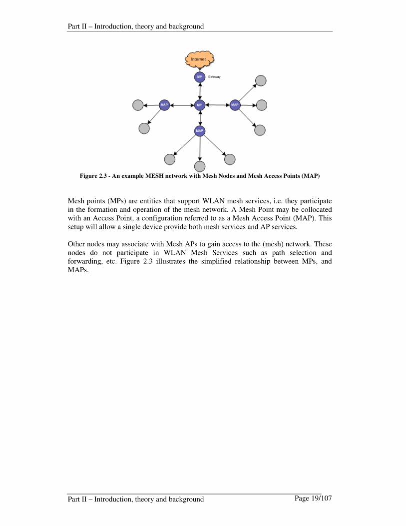
Figure 2.3 - An example MESH network with Mesh Nodes and Mesh Access Points (MAP)
Mesh points (MPs) are entities that support WLAN mesh services, i.e. they participate in the formation and operation of the mesh network. A Mesh Point may be collocated with an Access Point, a configuration referred to as a Mesh Access Point (MAP). This setup will allow a single device provide both mesh services and AP services. Other nodes may associate with Mesh APs to gain access to the (mesh) network. These nodes do not participate in WLAN Mesh Services such as path selection and forwarding, etc. Figure 2.3 illustrates the simplified relationship between MPs, and MAPs.

Part II – Introduction, theory and background
Part II – Introduction, theory and background Page 20/107
2.6.2 HWMP
The IEEE 802.11s work group has defined Hybrid Wireless Mesh Protocol (HWMP) as the mandatory protocol for networks as described in [13]. A secondary routing protocol called radio-aware OLSR, based on [16], was proposed as the optional routing protocol for MESH networks, but in late 2007 the protocol was removed from the draft amendment. This means that currently HWMP is the mandatory protocol to be used within 802.11s mesh networks (and the only one specified). It is inspired by a combination of reactive AODV and proactive OLSR based routing. The main reason was that the interesting features of RA-OLSR were already covered in the HWMP design. In addition they wanted to concentrate their work on a single routing protocol instead of two. The capabilities previously included in RA-OLSR is adopted and included in the HWMP specification.
2.6.3 RA-OLSR1
RA-OLSR was, until late 2007, a part of the IEEE 802.11s draft for Mesh networks. It defines how OLSR can be implemented using layer two addressing and radio properties to retrieve metrics. The airtime plug-in in the implementation in this thesis is based on ideas from this draft (i.e. the use of a Local Association Base set). However, even though the RA-OLSR specification was removed, the proactive Root announcement which borrowed from the OLSR HNA message, as well as airtime metric are still kept in HWMP.
1 In the latest 802.11s draft the RA-OLSR functionality has been removed. Some of the features are used in the HWMP specification. The airtime metric is still used in the draft.

Part II – Introduction, theory and background
Part II – Introduction, theory and background Page 21/107
2.7 802.11 Standards
The ANSI/IEEE workgroup for wireless network was established in 1997, and the initial 802.11 standard was released. Two years later, in 1999, they published the reclarified 802.11 standard described in [17]. Several additional standards on 802.11 has been published following this. Some of the most relevant are summarized in the table below:
Protocol Released Frequency Throughput
(Typical)
Data Rate
(Max)
Modulation
Technique
Legacy 1997 2.4 GHz 0.9 Mbit/s 2 Mbit/s 802.11a 1999 5 GHz 23 Mbit/s 54 Mbit/s OFDM 802.11b 1999 2.4 GHz 4.3 Mbit/s 11 Mbit/s DSSS 802.11g 2003 2.4 GHz 19 Mbit/s 54 Mbit/s OFDM 802.11n June 20092 2.4 GHz
5 GHz 74 Mbit/s 248 Mbit/s
Table 2-6 - An overview of the 802.11 wireless standards
In addition to the list above, a document released as 802.11-2007 includes all the amendments listed above.
2.7.1 802.11b
The 802.11b standard is described in [18]. It is normally used in Europe and operates in the 2.4 GHz open band, meaning that interference with other electronic equipment is an issue. To counteract the effects of this type of interference, 802.11b uses DSSS (Direct Sequence Spread Spectrum) with CCK. This means that the signal is spread on all available frequencies to be more resistant against noise. The data rates for 802.11b are 1,2,5.5 and 11Mbit/s.
2.7.2 802.11a
This standard, as described in [17], supports bandwidth up to 54Mbit/s and signals in the regulated 5 GHz band. The frequency used is one of the reasons that this standard is more frequently used in the states than in Europe. In Europe, this frequency is assigned to radar and satellite, but work is being done to give both technologies an opportunity to co-exist. 802.11a uses a modulation technology called OFDM (Orthogonal Frequency Division Multiplexing). This technology provides better bitrates and more available channels than spread spectrum technology. The higher frequency of 802.11a compared to 802.11b shortens the range of 802.11a networks. It also means that 802.11a signals have more difficulty penetrating walls and other obstructions. The data rates for 802.11a are typically 6, 9, 12, 18, 24, 36, 48 and 54Mbit/s.
2 Release dates are retrieved from http://grouper.ieee.org/groups/802/11/Reports/802.11_Timelines.htm

Part II – Introduction, theory and background
Part II – Introduction, theory and background Page 22/107
2.7.3 802.11g
The 802.11g standard as described in [19] is an evolution of 802.11b, using OFDM at speeds above 20 Mbps, and DSSS with CCK at speeds below that. The standard is backwards compatible with 802.11b as standardized in [18]. 802.11g attempts to combine the best of both 802.11a and 802.11b as it supports bandwidth up to 54 Mbps, and uses the 2.4 GHz frequency for greater range. It is also backwards compatible with 802.11b, meaning that 802.11g access points will work with 802.11b wireless network adapters and vice versa. The data rates for 802.11g are typically 6, 9, 12, 18, 24, 36, 48 and 54Mbit/s.
2.7.4 802.11n
The 802.11n standard extends the 802.11 standards by adding multiple-input multiple-output (MIMO), and 40 MHz operation on the physical layer. The idea is that several transmitter and receiver antennas are used to improve performance. In addition to support higher data rates, the 40 MHz operation uses wider bandwidth than the 20 MHz bandwidth used in legacy 802.11. According to the IEEE timelines (described in footnote on previous page) this specification is currently expected to be released in January 2009. (Draft 3.02 was approved during the Taipei meeting in January 2008).

Part II – Introduction, theory and background
Part II – Introduction, theory and background Page 23/107
2.8 The Wireless Extensions (WE) API
This chapter provides some background information on the wireless extensions API used by the airtime plug-in described in this thesis. The WE, as described in [20], were originally developed by J. Tourrilhes in 1997, and the idea was to provide better and more generic support for IEEE 802.11 WLANs in the
Linux environment. The WE is a generic ioctl based API, allowing a driver to expose configuration and statistics specific to common WLANs. Today, it is one of the most common methods used for interacting with WLAN devices in Linux. Although the name is Wireless Extensions, it is strictly concentrated around, and limited to, wireless LAN (i.e. Bluetooth /infrared devices are not supported). The WE is supported in most Linux kernel distributions. The WE must be supported by the device driver to function properly. Most drivers do
this either partially or fully. The driver can use the netdev->priv void
pointer to point to private information (i.e. to store a structure containing BSSID, mode and iwspy data). The latest version of the WE can be found in [20].
The normal method in Linux to interact with network devices is through the ioctl
kernel system call. The arguments of the ioctl call defines the operations to be done, the parameters of these operations and the device they applies to. These calls are normally operations performed on a file descriptor, but they can also be applied on a network socket. In example: To change the IP address on device eth0, a program (like ifconfig) would
make an ioctl call with the following parameters: ``eth0'', SIOCSIFADDR, new address. The structure defining the parameters layout may be found in
/usr/include/linux/if.h and the ioctl call (the constant SIOCSIFADDR)
is defined in /usr/include/linux/sockios.h. The wireless extensions are constructed in a similar manner, but with a number of new
ioctl calls and parameters. All the new ioctl calls and parameters are defined in
/usr/include/linux/wireless.h . Some examples of the ioctl used in this thesis are summarized below:
SIOCGIWMODE Get operating mode.
SIOCGIWNWID Get network ID.
SIOCGIWSPY Get spy info (link quality details).
SIOCGIWESSID Get ESSID.
SIOCGIWRATE Get bitrate.
Finally, the advantage of the ioctl method is that it is a programming interface, so any program (such as the airtime plug-in presented in this thesis) may manipulate them directly.

Part II – Introduction, theory and background
Part II – Introduction, theory and background Page 24/107
3 Overview of the UniK OLSRd In this chapter a brief introduction the UniK OLSRd features and implementation is given. This includes a description of the different message formats and repositories that are used.
3.1 Introduction
The UniK OLSRd [21] is an implementation of the OLSR protocol by Andreas Tønnesen, originally designed for GNU/Linux systems, but with support for other operating systems (i.e. Windows). The current implementation, without extensions, is compliant with the original OLSR RFC in [1]. The MF-OLSR implementation, described later in this thesis, is an extension to the existing UniK OLSRd implementation. It is therefore important to have a good understanding of the original design to understand the MF-OLSR implementation. OLSRd is a table driven routing protocol - so everything in OLSRd is basically concerned with maintaining tables describing the current state of the neighbors and the network topology. The implementation is made up of a variety of information repositories that can be queried for status information. The basic layout of OLSRd can be depicted as shown in Figure 3.1, originally published in [21].
Figure 3.1 - The OLSRd modular design overview
Starting from the left, incoming packets are handled by the socket parser. The incoming message is then handled by a method registered with the packet parser (multiple additional packet parser methods can be defined) depending on the message type. The packet parser method will handle the incoming message. The scheduler will make sure that appropriate methods for maintaining the repository tables and generating OLSR messages are executed on time.

Part II – Introduction, theory and background
Part II – Introduction, theory and background Page 25/107
3.2 Parsers
3.2.1 The packet parser
The packet parser receives all incoming OLSR traffic. Three options exists for the packet parser to handle incoming messages, these are:
1. Forward the packet according to the default forwarding algorithm. This is done
if the packet is valid, but the parser has no knowledge of this message-type. 2. Process the packet according to predefined rules. 3. Discard invalid/unknown packets
The internal method/process, to which a received message is sent, is responsible for updating the appropriate information repositories. Before the repositories are updated, the message is checked for validity, and that it is not already processed.
3.2.2 The socket parser
A function can register with the socket parser to listen for incoming data. This is described in more detail in Chapter 6.4 in [21].
3.3 Information repositories
According the original OLSR RFC in [1], a number of information repositories are maintained by the routing protocol. Figure 3.2, also published in [21], gives a schematic overview of the repositories that are affected by the different message types. Incoming messages are received on the INPUT side and delivered to specific repositories in the local node. On the OUTPUT side of the figure, it is illustrated how the different repositories will create and broadcast OLSR messages. Finally, the pointers to the route calculation box indicate which tables are used to perform the route calculation.
Figure 3.2 - An overview of the OLSRd message types and repositories

Part II – Introduction, theory and background
Part II – Introduction, theory and background Page 26/107
The information repositories depicted in Figure 3.2 are the "databases" in which OLSR keeps the information needed to at minimum describe the current state of the network. The various parsing functions both updates these tables and relies on information in these tables to be able to process the messages. All these tables are regularly "timed out". This means that entries no longer considered valid are removed from the repositories.
3.3.1 Link Set
The purpose of the link set is to maintain all links to the local nodes neighbors. All
these links are handled by the routing process, and stored in the link_set global variable. Each entry in the link set is stored in the link_entry structure listed below.
struct link_entry (depr.) {
union olsr_ip_addr local_iface_addr;
union olsr_ip_addr neighbor_iface_addr;
char *if_name;
clock_t SYM_time;
clock_t ASYM_time;
clock_t time;
struct neighbor_entry *neighbor;
olsr_u8_t prev_status;
struct link_entry *next;
};
extern struct link_entry *link_set;
3.3.2 Neighbor Set / 2 Hop Neighbor Set
The purpose of the neighbortable is to store information on adjacencies and the status of these. All neighbors handled by the routing protocol process are stored in the
neighbortable[HASHSIZE]. This table contains neighbor_entry structures as described below.
struct neighbor_entry {
union olsr_ip_addr neighbor_main_addr;
olsr_u8_t status;
olsr_u8_t willingness;
olsr_bool is_mpr;
olsr_bool was_mpr; /* detect changes in MPR */
olsr_bool skip;
int neighbor_2_nocov;
int linkcount;
struct neighbor_2_list_entry neighbor_2_list;
struct neighbor_entry *next;
struct neighbor_entry *prev;
};
extern struct neighbor_entry neighbortable[HASHSIZE];

Part II – Introduction, theory and background
Part II – Introduction, theory and background Page 27/107
3.3.3 MPR Set / MPR Selector set
The multipoint relay set contains a list of neighbors that are selected as MPR. In addition each node maintains a set of MPR-selector tuples describing the neighbor that have selected this node as the MPR. This information is vital for the optimization of topology control message distribution.
3.3.4 Topology Information Base
The topology information base contains the information on all other links in the routing domain. This information is used when routing calculation is performed.
struct tc_entry {
union olsr_ip_addr T_last_addr;
struct topo_dst destinations;
struct tc_entry *next;
struct tc_entry *prev;
};
extern struct tc_entry tc_table[HASHSIZE];
struct topo_dst {
union olsr_ip_addr T_dest_addr;
clock_t T_time;
olsr_u16_t T_seq;
struct topo_dst *next;
struct topo_dst *prev;
};
3.3.5 Host and Network Association (HNA) Set
The HNA set contains a list of the networks announced by other OLSR nodes in the topology. If the node itself is an HNA node there will also be a local HNA set in addition to the HNA set containing the external networks. The local HNA set will contain the network(s) that this node is advertising to the network.
struct hna_net
{
union olsr_ip_addr A_network_addr;
union hna_netmask A_netmask;
clock_t A_time;
struct hna_net *next;
struct hna_net *prev;
};
extern struct hna_entry hna_set[HASHSIZE];
struct hna_entry
{
union olsr_ip_addr A_gateway_addr;
struct hna_net networks;
struct hna_entry *next;
struct hna_entry *prev;
};

Part II – Introduction, theory and background
Part II – Introduction, theory and background Page 28/107
3.4 Link Quality extension
The RFC-compliant OLSRd implementation will calculate the shortest-path in terms of hop count between itself and the other nodes in the MANET. This means that a single hop bad link will be preferred to a route via a better two-hop link. To overcome this problem an experimental ETX (expected transmission count) like link quality metric was implemented as an extension to the original OLSRd. In short it means that unidirectional link quality metrics based on packet loss are distributed in the OLSR network. Finally, Dijkstras algorithm is used to calculate routes based on the ETX additive metric information in the topology table.
Figure 3.3 – The relationship between LQ and HELLO messages
LQ metrics are calculated by counting the number of HELLO messages that are lost between the local node and the neighbor. If, for example 3 out of 10 packets are lost from the neighbor to the local node, the probability that a message in this direction will be delivered ok is 70% (0.7). This is called the Link Quality. Measurements for packets sent in the opposite direction (from the local node to the neighbor), are called the Neighbor Link Quality. The product of the LQ and the NLQ is defined as the expected transmission count (ETX). This represents the probability for a packet round-trip. In the example in Figure 3.3, we see that 8/10 HELLO messages arrived with our neighbor and 7/10 HELLO messages was received correctly. This means we have a NLQ of (8/10) 0.8 and a LQ of 7/10 (0.7). The probability of a successful round trip is 0.7 x 0.8 = 0.56 = 56%.
3.4.1 Dijkstras algorithm for finding the shortest path
The shortest path algorithm will find the preferred path from all the nodes to node A.
1. Initially no paths are known (so all nodes are marked as tentative). 2. Node A (or working node) labeled as permanent. 3. Relabeling (tentatively) all directly adjacent nodes with the distance to A. (label
with path length and the name of the nodes adjacent to SN). 4. Examine all tentatively labeled neighboring nodes; Make the node with the
smallest label permanent. 5. This node will be the new working node for the iterative process. (Continue
with step 2).

Part II – Introduction, theory and background
Part II – Introduction, theory and background Page 29/107
Only minor modifications in the original OLSRd code have been performed for Dijkstra calculation of the shortest path. This feature was originally implemented in the Link Quality extensions of UniK OLSRd.
3.5 Plug-in architecture
The OLSRd plug-in architecture [22] was designed to provide the capability of adding additional functionality to the OLSRd without modifying the core code. The most important functionality is the ability to generate and process private package-types and other custom functionality. The concept is based on loading dynamically linked libraries (DLLs), referred to as plug-ins. The main drivers for using the plug-in architecture are:
1. The capability of sending broadcast traffic / private package-types using OLSR. 2. The capability of changing the OLSR functionality without modifying the
OLSR code. 3. The fact that plug-ins can be written in any language that can be compiled to a
DLL. 4. Easier patching of the base OLSRd.
The MF-OLSR implementation (described in chapter 5) includes the airtime and multihome plug-ins to achieve certain functionality.

Part III – Design
Part III – Design Page 30/107
Part III – Design Overview Part III of this thesis contains a design overview of the most important contributions of this thesis. This includes an overview of the MF-OLSR design and the plug-ins that are built around this framework.
4 MF-OLSR Design Overview The UniK OLSRd was originally implemented according to [1]. The problem with this implementation (and the original RFC), addressed in this thesis, is the hop count based path calculation. In its original design, important attributes like link errors, link data rate and link stability is not considered. Furthermore, it is well known that a purely hop count based path selection protocol will not give us the best path in a number of given situations. Figure 4.1 gives an overview of the MF-OLSR implementation and it also shows how the airtime plug-in fits in this design. By comparing Figure 4.1 with Figure 3.2 it should become clearer what the differences are between the original UniK OLSRd and MF-OLSR.
Figure 4.1 - A schematic overview of the MF-OLSR daemon and the airtime plug-in

Part III – Design
Part III – Design Page 31/107
To solve some of the challenges related to these problems a series of additional plug-ins was developed for OLSRd (one of these being the LQ functionality). By enabling some of these additional features, we break RFC compliance. This means that all nodes in the OLSR domain must run with the same enhancements to be fully compliant with each other. Inside an AS3 this will normally be possible. In order to support metric-based routing in OLSR, an extension of the existing HELLO, TC and HNA messages were implemented. The purpose was to carry necessary metrics for neighbor, link and topology dissemination. These features are implemented in a generic framework, proposed and designed by this thesis. This framework is referred to as MF-OLSR (Metric-based Framework for OLSR). The MF-OLSR includes the new message types MF-HELLO, MF-TC and MF-HNA messages. These message types are all capable of carrying single or multiple metric values and metric types. The ability to carry several metrics allows us to deploy both LQ metrics and airtime metrics in the same domain. In other words, the implemented MF-OLSR described in this paper can be used for multiple metrics. In the following Chapters, the different aspects that are affected by the extended design and new features will be described. The following topics are described:
• An overview of the extended MF-OLSR message types
• A briefing on the modified repositories
• Information on the new plugins
• An introduction to the Local Association Base (LAB).
3 Autonomous System (normally within a company / routing domain)

Part III – Design
Part III – Design Page 32/107
4.1 An overview of the implemented improvements in MF-OLSR
The improvements implemented in this thesis involved rewriting major parts of the existing UniK OLSRd code. The most important aspects of these changes are;
• New OLSR message types; MF-HELLO, MF-TC and MF-HNA
• Introduction of Airtime Metric Plug-in, Multihoming Plug-in and HTTPInfo+ Plug-in. The common denominator is that a metric value and metric type is added to HELLO and TC messages. The HNA messages, from now on called MF-HNA contains a new gateway status value and a gateway metric type field. Enabling the metric framework will (similar to the link quality extensions) leave the OLSR implementation non-RFC compliant In the enhancements described in this paper, no modifications to the general OLSR packet format are implemented. All modifications are performed on HELLO, TC and HNA messages. These modifications are described in detail in the next section. Note! The enhancements that are implemented in this thesis will break compliance with the original OLSR RFC and we are making modifications to the auxiliary functionality that will not work with other OLSR implementations.

Part III – Design
Part III – Design Page 33/107
4.2 MF-OLSR w/airtime plug-in example
The example below is given to illustrate how MF-OLSR will work using the airtime plug-in. Given the scenario below: In Figure 4.2 the shortest–path is calculated based on the airtime metric.
Figure 4.2 – An example MANET running MF-OLSR where airtime metric shortest path has been
calculated and a path from C to E is selected
Node A B C D E F G
A b g b
B b b a
C g g a
D b b g g b b
E a g a
F a b b
G b a b
Table 4-1 – MF-OLSR example: Nodes Radio type
Table 4-1 shows the radio types in use in the example scenario in Figure 4.2. The radio types used are important for the airtime metric calculation, as some of the constant values in the equation will vary based on this.

Part III – Design
Part III – Design Page 34/107
Node A B C D E F G
A 11 54 5.5
B 11 11 12
C 54 54 48
D 5.5 11 54 11 11 11
E 12 11 24
F 48 11 11
G 11 24 11 Table 4-2 – MF-OLSR example: Bit rate
Table 4-2 lists the bitrates used for the different nodes.
Node A B C D E F G
A 5% 20% 2%
B 5% 2% 5%
C 20% 5% 4%
D 2% 2% 5% 12% 10% 5%
E 5% 12% 5%
F 4% 10% 0%
G 5% 5% 0%
Table 4-3 - MF-OLSR example: Error probability
Table 4-3 lists the simplified error probability (calculated using LQ metric values). The error probability is an important factor in the airtime metric calculation as it will severely impact the outcome.

Part III – Design
Part III – Design Page 35/107
4.3 Overview of Link Metric Types and Link Metric Values
The list of link metric types defined by this thesis, in MF-OLSR is listed in Table 4-4 – The constant values defined for the various Link Metric Types. Initially, only the LMT_AIRTIME and LMT_COST will be implemented in MF-OLSR. The additional metrics are provided to give an indication of what type of metrics that can be included for future use.
Link Metric Type Value LMT_NULL 0
LMT_BW 1
LMT_DELAY 2
LMT_LOAD 4
LMT_COST 8
LMT_RES_BW 16
LMT_AIRTIME 32
LMT_LQ 64
DEF_LMT LMT_COST
Table 4-4 – The constant values defined for the various Link Metric Types likely to be used in metric
operations (only some of them used in this implementation).
Table 4-5 contains an overview of the default values that will be assigned to the various link metric types listed in Table 4-4, if no value is assigned or can be retrieved automatically. It also contains the value bounds for each metric type.
Link Metric Values Metric Min Max Default
Bandwidth MIN_IF_BANDWIDTH MAX_IF_BANDWIDTH DEF_IF_BANDWIDTH
Delay MIN_IF_DELAY MAX_IF_DELAY DEF_IF_DELAY
Load MIN_IF_LOAD MAX_IF_LOAD DEF_IF_LOAD
Cost MIN_IF_COST MAX_IF_COST DEF_IF_COST
Airtime MIN_IF_AIRTIME MAX_IF_AIRTIME DEF_IF_AIRTIME
Table 4-5 – The defined Link Metric Value bounds and default values

Part III – Design
Part III – Design Page 36/107
4.4 Overview of MF-HELLO messaging
MF-HELLO messages are used (when received) to populate the local link set and the neighborhood set. Additionally, MF-HELLO messages are generated and sent using information in the local link set, the neighborhood set and the MPR set from the local link
information base. The difference between the original HELLO messages and MF-HELLO messages are that the latter are constructed with additional fields to populate metric information.
4.4.1 The MF-HELLO message packet format
The table below describes how the HELLO message packet format is extended to carry a single or multiple Link Metric Values and Link Metric Types. The Link Message Size calculates the size from the Link Code field to, and including, the last Link Metric Type field for the specific Neighbor Interface Address. The Reserved field is currently not utilized.
The MF-HELLO packet format is implemented in src\mf_packet.h 0 1 2 3
0 1 2 3 4 5 6 7 8 9 0 1 2 3 4 5 6 7 8 9 0 1 2 3 4 5 6 7 8 9 0 1
Reserved Htime Willingness
Link Code Reserved Link Message Size (16)
Neighbor Interface Address
Link Metric Value Reserved Link Metric Type
Link Metric Value Reserved Link Metric Type
Link Code Reserved Link Message Size (16)
Neighbor Interface Address
Link Metric Value Reserved Link Metric Type
Link Metric Value Reserved Link Metric Type
Table 4-6 – MF-HELLO message with two neighbors carrying two metrics each
The example HELLO message above contains two link metric values for the first neighbor. This illustrates how several metrics can be populated in the same HELLO message. There is currently no use of the additional link code field and reserved field for the additional neighbors. It should be possible to optimize this packet format with fewer fields.
4.4.2 Link Sensing and Neighbor discovery using MF-HELLO
As explained previously the main purpose of HELLO messages is to detect neighbors and hence update the local link information set and the neighbor sets. The information advertised in the MF-HELLO messages are retrieved from the link set. The metrics in the link set could i.e. be updated by the airtime metric. HELLO messages are, by default, transmitted every two seconds. A graphical representation of the process is outlined below.

Part III – Design
Part III – Design Page 37/107
Figure 4.3 - Neighbor discovery process
1. The first MF-HELLO message broadcasted by Node A will be received by all nodes in the broadcast domain and recognized as sourced from Node A (by IP address). At this stage the local link information set in both nodes are empty.
2. After receiving the MF-HELLO message from Node A, Node B will send a unicast
MF-HELLO message to Node A including it as an ASYM neighbor in the message. This message will also include selected metrics. The metrics will primarily be retrieved from the link set or interface. If no metrics can be retrieved a default value will be assigned.
3. After receiving the MF-HELLO message from Node B where Node A is
acknowledged as a neighbor, Node A then sends a new MF-HELLO message including Node B as a SYM neighbor. Metrics are also included in this message.
4. Finally Node B acknowledge Node A as a neighbor by sending a HELLO message
including Node A as a SYM neighbor. Metrics are also included in this message.

Part III – Design
Part III – Design Page 38/107
4.5 Overview of MF-TC messaging
Received MF-TC messages are used to populate the topology set. Additionally, MF-TC messages are generated and sent using information in the local link set. The difference between the original TC messages and MF-TC messages, are that the latter are constructed with additional fields to populate metric information.
4.5.1 The MF-TC message packet format
In Table 4-7 it is illustrated how the TC message packet format is extended to carry a single or multiple Link Metric Value and Link Metric Type. The MoreMetrics field indicates if more metrics are expected to follow the current metric. This is needed for calculating the start of the next advertised neighbor main address or the end of the message. The value for MoreMetrics can be either 0 (FALSE) or 1 (TRUE).
The MF-TC packet format is defined in src/mf_packet.h 0 1 2 3
0 1 2 3 4 5 6 7 8 9 0 1 2 3 4 5 6 7 8 9 0 1 2 3 4 5 6 7 8 9 0 1
ANSN Size
Advertised Neighbor Main Address
Link Metric Value MoreMetrics Link Metric Type
Advertised Neighbor Main Address
Link Metric Value MoreMetrics Link Metric Type
Link Metric Value MoreMetrics Link Metric Type
Table 4-7 – MF-TC message packet format with two neighbors
4.5.2 Topology generation using MF-TC messages
MF-TC messages will be generated in predefined intervals specified in OLSR [1] or as configured in the UniK OLSRd configuration file. Upon constructing the MF-TC message,
the link set will be queried for the appropriate metric information. (i.e. L_metric_type,
L_metric_value). These will be related to the specific neighbor IP.

Part III – Design
Part III – Design Page 39/107
4.6 Overview of MF-HNA messaging
MF-HNA messages are used to disseminate information on available networks through a specific node. Initially it is the content of the local hna set that is distributed in these types of messages. Additionally, received MF-HNA messages are added to the hna set containing all the advertised networks available. The difference between the original HNA messages and MF-HNA messages, are that the latter are constructed with additional fields to populate metric information. If the OLSR auxiliary HNA functionality is enabled, MF-HNA messages will automatically be generated every HNA_INTERVAL seconds (normally five) according to the recommendations in [1] or as configured in the OLSRd configuration file. These settings can be controlled per interface. The message will be constructed using information in the local HNA set4 as described in chapter 4.6.2.
4.6.1 The MF-HNA message packet format
The structure that keeps the HNA message before it is serialized to the socket, are
mf_hnamsg, mf_hnapair and mf_hnametric (IPv4) defined in src\mf_packet.h . The file contains a description of all packet formats used in MF-OLSR (currently only the IPv4 version is implemented). The table below depicts the layout of the data portion in the OLSR message containing the MF-HNA message type. 0 1 2 3
0 1 2 3 4 5 6 7 8 9 0 1 2 3 4 5 6 7 8 9 0 1 2 3 4 5 6 7 8 9 0 1
Network Address
Network Mask
Gateway Status Value Reserved Gateway Metric Type
Table 4-8 - Extended HNA message packet format
4 If the multihome plug-in is enabled, metrics will be added to the MF-HNA messages.

Part III – Design
Part III – Design Page 40/107
4.6.2 Dissemination of MF-HNA messages
MF-HNA messaging are disseminated when the Hna4 section of the original UniK OLSRd configuration file is configured. Let’s look at an example:
Hna4
{
0.0.0.0 0.0.0.0
192.168.100.0 255.255.255.0
}
This configuration will enable the node to send MF-HNA messages populating the Network
Address and Network Mask field with the values configured above. If the multihoming plug-in is not enabled, the Gateway Status Value and Gateway Metric Type will be assigned default
values. The default values listed below are defined in src/mf_defs.h.
#define DEF_GW_STATUS_VALUE 1000
#define DEF_GW_METRIC_TYPE GWMT_NULL

Part III – Design
Part III – Design Page 41/107
4.7 Overview of the MAC address based Local Association Base (LAB)
The LAB set is a new feature adopted from an early RA-OLSR draft specification [13]. In later versions of this draft the RA-OLSR functionality has been removed. Still the ideas are valid for experimenting with path selection for the OLSR routing protocol. The design and implementation of the LAB set for MF-OLSR is a part of this thesis. The purpose of the LAB set is to maintain wireless statistics for each neighbor. Methods for retrieving this information will depend on the operating system, but for the version implemented in this thesis, information is retrieved using the wireless extensions included in the Linux kernel distribution. The information retrieved is the same information that is displayed when utilizing the iwspy command. The structure below shows the attributes5 that are included in a lab set entry in MF-OLSR.
struct lab_entry
{
olsr_mac_addr *local_mac_addr;
olsr_mac_addr *neighbor_mac_addr;
union olsr_ip_addr local_ip_addr;
union olsr_ip_addr neighbor_ip_addr;
char *ifname; // ifn->ifname
olsr_u32_t iwspy_link_quality;
olsr_u32_t iwspy_qual_range;
olsr_u32_t iwspy_signal_strength;
olsr_u32_t iwspy_signal_noise;
olsr_bool monitored;
olsr_u32_t update_count; /* debug */
clock_t time;
clock_t hello_timeout;
clock_t htime;
olsr_u16_t radio_type; /* 802.11 radio type */
olsr_u16_t bits_in_testframe;
olsr_u16_t protocol_overhead; /* Depends on radio type */
olsr_u16_t error_prob; /* ETX value */
olsr_u16_t bitrate; /* Calculated bitrate from iwspy */
/* Airtime metrics and historic airtime metrics */
olsr_u16_t last_airtime_transferred;
olsr_u16_t current_airtime;
olsr_u16_t trigger;
olsr_u16_t airtime_history;
struct interface *ifn;
struct lab_entry *next;
};
An example of the data registered in the lab set is shown in Figure 5.6
5 Some of the attributes listed are just placeholders for future extensions/usage.

Part III – Design
Part III – Design Page 42/107
5 MF-OLSR Plug-ins Design Overview This chapter gives an overview of the airtime plug-in, the multihoming plug-in and the extended httpinfo+ plug-in designs. More details on the implementation of the plug-ins are given in Part IV - Chapter 7 and Chapter 8.
5.1 Overview of the Airtime Plug-in
In the last few years there have been increasing interests in cross layer design in the wireless research community. Some researchers also see this as a paradigm shift from the traditional layered network architecture. The reason for this is that the calculation of routes in MANETs requires information from several of the traditional OSI layers. However, making a cross-layer design that retrieves wireless statistics, introduces challenges in finding a good and practical method to retrieve and interpret the data needed. The ability to do radio-aware path selection requires a method to retrieve attributes of the link layer / physical layer. This is the purpose of the airtime plug-in (the implementation is described in more detail in chapter 8). The primary task of the airtime plug-in is to keep track of our associated neighbors and update the attributes in the local association base. This information will make it possible to calculate the airtime metric described in the next chapter. Calculating the airtime metric and transferring this to the different tables, is the secondary task for the airtime plug-in. The current calculation is highly influenced by ideas brought forward in the RA-OLSR specification.
Figure 5.1 – A schematic overview of the Airtime plug-in design

Part III – Design
Part III – Design Page 43/107
5.1.1 Airtime metric calculation
The airtime metric described in [13] is approximate and designed for ease of implementation and interoperability. The formula below is referenced from the RA-OLSR section of [13].
pt
ta
er
BOc
−
+=
1
1
Figure 5.2 - Simplified formula for calculating airtime metric
The overhead values (defined as O in the equation) equals the combined channel and protocol overhead values defined in Table 5-1.
Parameter Value (802.11a) Value (802.11b/g) Description
caO 75 sµ 335 sµ Channel access overhead
pO 110 sµ 364 sµ Protocol overhead
tB 8224 8224 Number of bits in test frame
Table 5-1 - Airtime Cost Constant values
Parameter Description Determined
pte Error Frame Rate During Link State Discovery Phase
r Data rate During Link State Discovery Phase Table 5-2 - Airtime Cost Dynamic values

Part III – Design
Part III – Design Page 44/107
5.2 Overview of the Multihoming Plug-in
The multihoming plug-in controls the metric content of the disseminated MF-HNA messages. The purpose is to announce gateway suitability for specific remote networks (i.e. internet connectivity).
5.2.1 Introduction to MF-HNA messaging
Advertising external networks and hosts are part of the auxiliary functionality of the OLSR specification. Basically it means that a node can advertise itself as a gateway to specific network(s), i.e. Internet, by issuing Host and Network Association messages (HNA). In the UniK OLSR daemon implementation of OLSR, this functionality is implemented according to the specifications in [1]. If several gateways are available, OLSR will choose the path with the lowest hop counts to the gateway. The MF-HNA message format introduced in this thesis describes how metrics are used to achieve more flexibility when dealing with multihome network situations. The HNA message format is extended with a metric and type attribute described in detail in chapter 4.6 in this thesis.
5.2.2 Current problem with hop count multihoming
For the routes to be calculated correctly all intermediate nodes must support processing and/or forwarding of HNA messages. In the UniK OLSRd implementation node B and C will select the path with the lowest hop count as illustrated in Figure 5.3.
Figure 5.3 – An illustration of the problem with HNA hop count metric selection
In the scenario in Figure 5.3, node B will select the path to node A for Internet traffic even though this host is currently overloaded. Ideally we would like to have a more optimal way of choosing the best path to Internet. We might have situations where the gateway is overloaded or the links in the paths from B to A is congested etc. Currently these are limitations in the original RFC. For the enhancements described in this thesis, the basic idea is that the gateway can announce a status value describing the suitability
of this specific node as a gateway to specific external networks. The sending node should again reflect this value in its routing table.

Part III – Design
Part III – Design Page 45/107
5.2.3 Example scenario using the extended HNA messages
Figure 5.4In Figure 5.4 a simple scenario for demonstrating HNA gateway selection based on gateway status value and gateway metric type is given. Node A and D are advertising availability for 0.0.0.0 through their respective internet connection. Both nodes B and C will select the route through node D, because the total metric value is the lowest.
Figure 5.4 – An improved path selection in multihomed networks using MF-HNA messages

Part III – Design
Part III – Design Page 46/107
5.3 Overview of the Httpinfo+ Plug-in
The Httpinfo+ plug-in is more or less a copy of the original Httpinfo plug-in implemented for the Unik OLSRd, but with additional features to accommodate the additional plug-ins in MF-OLSR. The main purpose of the updated plug-in, was the need to be able to see the status of the modified and additional repositories at any given time. The web based view, depicted below, of the content in the different data sets, gives a good indication of how the protocol is performing.
Figure 5.5 – A snapshot of the Httpinfo+ configuration web interface
From the interface above we can see how the status value and the metric type in the MF-HNA messages are presented in the Web interface. When the airtime plug-in is enabled, two additional tabs will be visible as depicted below. Also, we can see that the RADIO: type is unknown. This is due to the fact that we are not running the airtime plug-in (in the example above).
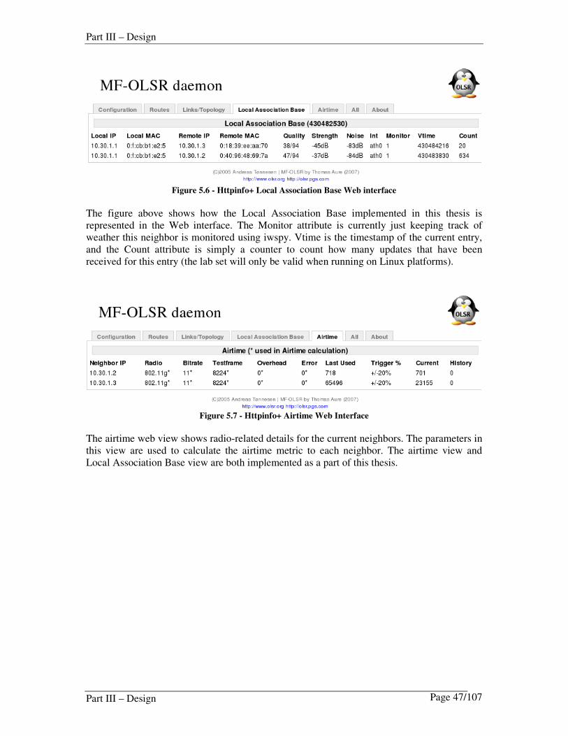
Part III – Design
Part III – Design Page 47/107
Figure 5.6 - Httpinfo+ Local Association Base Web interface
The figure above shows how the Local Association Base implemented in this thesis is represented in the Web interface. The Monitor attribute is currently just keeping track of weather this neighbor is monitored using iwspy. Vtime is the timestamp of the current entry, and the Count attribute is simply a counter to count how many updates that have been received for this entry (the lab set will only be valid when running on Linux platforms).
Figure 5.7 - Httpinfo+ Airtime Web Interface
The airtime web view shows radio-related details for the current neighbors. The parameters in this view are used to calculate the airtime metric to each neighbor. The airtime view and Local Association Base view are both implemented as a part of this thesis.

Part IV – Implementation
Part IV – Implementation Page 48/107
Part IV – Implementation Based on the design principle described in Part III, this part describes how the designed framework is implemented, including the MF-OLSR implementation details, the multi-homing plug-in and the airtime metric plug-in.
6 MF-OLSR Implementation Details In this chapter a more detailed explanation of the MF-OLSR implementation is provided. I.e. the packet format structures and the dissemination and handling of messages, will be explained in detail.
6.1 MF-OLSR files
The implementation of the MF-OLSR extensions involves several modifications to the original UniK OLSRd code. An effort has been made to avoid changing too much of the existing code while implementing the new functionality, but for some parts of the extensions, modifications were necessary. The table below gives an overview of the additional files included in MF-OLSR. In general,
all MF-OLSR functionality is implemented in files starting with “mf_” i.e. mf_packet.c
File Header file Comment
mf_olsr_main.c mf_olsr_main.h Main MF-OLSR methods
mf_defs.c Definitions / constants
mf_packet.c mf_packet.h Packet parsers
mf_route.c mf_route.h Route calculation
mf_list.c mf_list.h Route calculation
mf_avl.c mf_avl.h
mf_lab_set.c mf_lab_set.h Local Association Base
mf_mpr.c mf_mpr.h
Table 6-1 - Additional files included for MF-OLSR

Part IV – Implementation
Part IV – Implementation Page 49/107
The structure in Figure 6.1 shows the basic layout of the source code for MF-OLSR (it is basically the same as for UniK OLSRd). Modifications to existing UniK OLSRd files are commented in the source code of the changed file. Details on compiling and running MF-OLSR, are given in the “Compilation and usage” appendix.
Figure 6.1 - MF-OLSR source code file structure layout
Modifications to existing UniK OLSRd files are commented in the source code of the changed file, as follows: /* MF-OLSR */. This should make it somewhat easier to spot the modified or extra code.

Part IV – Implementation
Part IV – Implementation Page 50/107
6.2 Registration of the packet generation methods
Packet generator methods are registered with the scheduler in /src/win32/ifnet.c or /src/unix/ifnet.c (depending on operating system). This is where we decide what functions/methods to use for MF-OLSR message generation. The code below describes how the proper message generation method, developed in MF-OLSR, is executed based on specific intervals (described in the configuration). These modifications are performed directly in the original UniK OLSRd code.
if (olsr_cnf->mf_level > 0 ) {
olsr_register_scheduler_event(&olsr_output_mf_hello, ifp,
iface->cnf->hello_params.emission_interval,0, NULL);
olsr_register_scheduler_event(&olsr_output_mf_tc, ifp,
iface->cnf->tc_params.emission_interval,0, NULL);
}
olsr_register_scheduler_event(&olsr_output_mf_hna, ifp,
iface->cnf->hna_params.emission_interval,0, NULL);
The test for mf_level has been modified several places in the UniK OLSRd implementation. Note that LQ calculation will always be performed when the metric framework extensions are enabled.
6.3 Registration of the packet parser methods
Parser functions for the MF-OLSR messages are registered in the method called
olsr_init_package_process in src/process_package.c. The methods defined here are executed when a message of the defined type is received. These modifications are also performed directly in the UniK OLSRd code. ……………else if (olsr_cnf->mf_level > 1) {
olsr_parser_add_function(&olsr_input_mf_hello, MF_HELLO_MESSAGE, 1);
olsr_parser_add_function(&olsr_input_mf_tc, MF_TC_MESSAGE, 1);
}
olsr_parser_add_function(&olsr_input_mf_hna, MF_HNA_MESSAGE, 1);
All arriving packets are handled by the packet parser defined in src/parser.c, and the appropriate methods are called depending on the type of message. In addition, some statistics are updated and additional checks are performed. The packet generation method and the packet parser method are generally the methods that kick of the OLSR routing process. It is therefore vital for the operation of the routing protocol. In the next chapter we will take a closer look at the methods that are executed when a message is received or sent.

Part IV – Implementation
Part IV – Implementation Page 51/107
6.4 Implementation of MF-HELLO messaging
The MF-HELLO message is an extended version of the HELLO message designed to exchange metric information with neighbors. The implementation is designed so that several metrics can be included for each neighbor advertised in the MF-HELLO message. The metric values currently allowed can be in the range from 0 to 65536, and have a metric type of 0 to 255. A metric is always advertised as a pair, consisting of a link metric value and a link metric type. The extensions are implemented in a similar manner as the LQ extensions, but the metrics that can be carried are more generic. The link metric attributes can be populated using plugins written for the plug-in framework.
6.4.1 The MF-HELLO message packet format and memory structure
The structures that hold the MF-HELLO message in memory before serialization, is defined
in src\mf_packet.h. The change from the original implementation is the addition of the
mf_neighbor_metrics structure and the modified mf_hello_neighbor structure,
including the metrics as a linked list.
struct mf_neighbor_metrics
{
olsr_u16_t link_metric_value;
olsr_u8_t link_metric_type;
struct neighbor_metrics *next;
};
struct mf_hello_neighbor
{
olsr_u8_t status;
olsr_u8_t link;
olsr_u8_t link_code;
olsr_u8_t link_type;
olsr_u8_t neigh_type;
double link_quality;
double neigh_link_quality;
union olsr_ip_addr main_address;
union olsr_ip_addr address;
struct mf_neighbor_metrics *metrics;
struct hello_neighbor *next;
};
struct mf_hello_message
{
struct mf_olsr_common comm;
double htime;
olsr_u8_t will;
olsr_u8_t colocated_i;
struct hello_neighbor *neighbors;
};

Part IV – Implementation
Part IV – Implementation Page 52/107
Figure 6.2 – The relationship between the MF-HELLO message deserialized structures
Before the MF-HELLO message is serialized, it will be copied from the structures that keep the messages in memory, to the structures described below. These structures are also defined
in src/mf_packet.h
struct mf_hello_metric
{
olsr_u16_t link_metric_value;
olsr_u8_t reserved;
olsr_u8_t link_metric_type;
} __attribute__ ((packed));
struct mf_hello_info_header
{
olsr_u8_t link_code;
olsr_u8_t reserved;
olsr_u16_t size;
} __attribute__ ((packed));
struct mf_hello_header
{
olsr_u16_t reserved;
olsr_u8_t htime;
olsr_u8_t willingness;
} __attribute__ ((packed));
These structures construct the message format as described in Chapter 4.4.1

Part IV – Implementation
Part IV – Implementation Page 53/107
6.4.2 Building and serializing MF-HELLO messages
The main purpose of the MF-HELLO message, is to do link detection and to establish adjacencies. Secondly it also has the capability of exchanging metric information with all neighbours.
The olsr_output_mf_hello method in src/mf_packet.c, is registered with the scheduler to generate the MF-HELLO messages (this is explained in chapter 6.2). This method is the main entry point for MF-OLSR message generation, and it will be executed in regular predefined intervals, defined in the registration of the method (normally this is every two seconds). The most important methods involved in creating the MF-HELLO message are outlined in Figure 6.3 (other MF-OLSR messages are created in a similar matter):
Figure 6.3 – An overview of the MF-HELLO message generation process
1. Primarily, the create_mf_hello (src/mf_packet.c) method will be executed.
The purpose of this method is to create and fill the mf_hello_message structure based on information in the link set. For each link we create metrics as outlined below:
neigh->metrics = NULL; // clear the metrics list
/* Retrieve and assign the metric type and value in the link entry */
metric = olsr_create_metric(walker->L_metric_type, walker->L_metric_value);
metric->next = neigh->metrics;
neigh->metrics = metric; // assign metrics to the neighbor.
/* LQ and NLQ metrics are put in the HELLO message, but they are only used
* for calculating the error probability between two neighbors. */
metric = olsr_create_metric(LMT_LQ, walker->loss_link_quality * 255);
metric->next = neigh->metrics;
neigh->metrics = metric; // assign metrics to the neighbor.
metric = olsr_create_metric(LMT_NLQ, walker->neigh_link_quality * 255);
metric->next = neigh->metrics;
neigh->metrics = metric; // assign metrics to the neighbor.
2. After the MF-HELLO message is constructed in memory, the
serialize_mf_hello method is executed to serialize the finished message to the socket. This method is actually constructing the packet by copying attributes to a buffer according to the packet layout. The additional MF-HELLO structures are used for navigating within the buffer.
3. Finally, the memory buffers and structures will be released for objects not being used
anymore.

Part IV – Implementation
Part IV – Implementation Page 54/107
6.4.3 Receiving and processing MF-HELLO messages
The olsr_input_mf_hello method is registered with the packet parser to handle incoming MF-HELLO messages (this is described in chapter 6.3). The most important methods involved in handling incoming MF-HELLO messages are outlined below (other MF-OLSR messages are created in a similar matter):
Figure 6.4 – An overview of the MF-HELLO message handling process
1. The purpose of the deserialize_mf_hello method is to copy the packet in buffer to a memory structure that can be handled more easily. This is performed by copying
the message(s) in buffer to the mf_hello_message structure called mf_hello.
2. In this second step, changes related to the integration between MF-OLSR and OLSR are performed. (For the most part this is related to the process of copy data between data structures). The reason for this step is that we need to send the message to other additional handling procedures in the OLSR daemon. This step is basically not wanted, but is currently the only way that information can be easily passed to the original daemon. The alternatives are to rewrite more of the original code.
3. The purpose of the olsr_hello_tap method (in src/process_packet.c) is to
process the packet and update the appropriate link_entry. This method is from the original UniK OLSRd implementation. This method works on the data structures that we copied information into in the previous step (step 2).
4. Finally, the memory buffers and structures will be released for objects not being used
anymore.
After performing the process described above, the incoming message is received and handled by the routing protocol.

Part IV – Implementation
Part IV – Implementation Page 55/107
6.4.4 The Local Link Set
The link set is maybe the most important source of information for the routing daemon. This is where information will be retrieved and updated related to path availability. The link set is updated based on received MF-HELLO messages. This periodic emission of messages constructs a local link set describing the links between local interfaces and remote interfaces.
It is therefore important that the link_entry in the link set contains the appropriate attributes to contain the metric information. The information in the local link set is also used when advertising neighbor interfaces with metrics, in MF-HELLO messages. The additional attributes included in the link set to accommodate the metric framework are L_metric_type and L_metric_value.
Figure 6.5 - Example attributes of the link_entry structure
In this version of MF-OLSR it will only be possible to advertise one single metric in addition to the link quality information that is exchanged in MF-HELLO messages. This metric value
and type will be kept in L_metric_value and L_metric_type. Instead of using generic attributes for the metrics, it could be possible in future versions to
store multiple different metrics in the same link entry (i.e. by using attributes L_cost,
L_delay). I have therefore included these as placeholders in the link_entry structure for
future use. The following attributes are added to the link_entry structure in
src/link_set.h (the structure is deprecated):
struct link_entry
{
…….
olsr_u8_t L_metric_type;
olsr_u16_t L_metric_value;
olsr_u16_t L_cost;
olsr_u16_t L_airtime;
olsr_u16_t L_delay;
olsr_u16_t L_reversed_airtime;
…….
};
The link set is always available as extern struct link_entry *link_set;

Part IV – Implementation
Part IV – Implementation Page 56/107
6.5 Implementation of MF-TC messaging
The MF-TC message is an extended version of the TC message designed to flood link state information in the network. The implementation is designed so that several metrics can be advertised for each neighbor advertised in the MF-TC message. The metric values currently allowed can be in the range from 0 to 65536 and have a metric type of 0 to 255. A metric is always advertised as a pair consisting of a metric value and a metric type.
6.5.1 MF-TC message packet format and memory structure
All link state protocols are based on nodes flooding the network with information about their links. In OLSR, MF-TC messages are used to inform nodes about the links to the neighbors of the sender of the MF-TC message. This information is emitted in MF-TC messages and used to maintain the topology information base in each node. MF-TC messages are flooded using the MPR optimization, but also when changes to the topology occur. For more information on optimizations introduced with the MPR functionality see details in [21] and [1] and in chapter 2.3.4 in this thesis.
The MF-TC message is serialized to the network according to the structures depicted below. These structures will fit to the packet format as illustrated in Table 2-3
struct mf_tc_serialized_metric
{
olsr_u16_t link_metric_value;
olsr_u8_t more_metrics;
olsr_u8_t link_metric_type;
} __attribute__ ((packed));
struct mf_tc_serialized_neighbor
{
union olsr_ip_addr addr;
} __attribute__ ((packed));
struct mf_tc_serialized_header
{
olsr_u16_t ansn;
olsr_u16_t size;
} __attribute__ ((packed));

Part IV – Implementation
Part IV – Implementation Page 57/107
The structure that holds the MF-TC message in memory is defined in src\mf_packet.h The modifications below will enable the node to hold several metric values and metric types per advertised neighbor.
struct mf_tc_neighbor
{
double link_quality;
double neigh_link_quality;
struct mf_neighbor_metrics *metrics;
union olsr_ip_addr main;
struct mf_tc_neighbor *next;
};
struct mf_tc_message
{
struct mf_olsr_common comm;
union olsr_ip_addr from;
olsr_u16_t ansn;
struct mf_tc_neighbor *neigh;
};
The relationship between the different structures that holds the MF-TC message in memory are illustrated in Figure 6.6
Figure 6.6 – The relationship between the MF-TC message deserialized structures

Part IV – Implementation
Part IV – Implementation Page 58/107
6.5.2 Building and serializing the MF-TC message
The main purpose of the MF-TC message is to broadcast topology information in the OLSR
domain. The olsr_output_mf_tc method in src/mf_packet.c is registered with the scheduler to generate the MF-TC messages (this is explained in chapter 6.2). This method is the main entry point for MF-TC message generation and it will be executed in regular predefined intervals, defined in the registration of the method. The most important methods involved in creating the MF-TC message are outlined below:
Figure 6.7 – An overview of the MF-TC message generation process
1. MF-TC messages are constructed in the create_mf_tc method (in
src/mf_packet.c). Common OLSR header information like type, vtime, size,
originator, hops, seqno, ansn, from and TTL will be assigned. The TTL attribute will get a value of MAX_TTL if we are running without any optimizations6. Finally, all neighbours will be traversed and the appropriate objects added to the final MF-TC message. While traversing neighbours, the best link to each neighbour will also be added to the MF-TC message. This is the entity that contains metric information for the associated neighbour. If there are no metrics to advertise, a default metric LMT_NULL will be added to the MF-TC message to comply with the standard packet format (this is basically a waste of space, but currently the only option to keep track of metrics in the packet).
2. After the successful construction of the MF-TC message, it needs to be serialized.
The purpose of the serialization is to copy the packet content to a buffer, ready to be
transmitted. This is handled by the serialize_mf_tc method. The packet as held in memory is traversed and copied to the serialization structures. In this process, we
also calculate the size of the MF-TC message and the more_metrics attributes in the metric serialization. The final operation in this method is to send the message
using the net_outbuffer_push method.
3. Finally the memory allocated will be released. Note: By default only the MPRS (multipoint relay selector set) (=nodes using this node as the MPR)
will be added to the TC message.
6 If running the fisheye algorithm, implemented later for Unik OLSRd, the TTL will be more dynamic.

Part IV – Implementation
Part IV – Implementation Page 59/107
6.5.3 Receiving and processing MF-TC message
The methods that process TC messages are modified to handle the extended packet format.
Most importantly we need to verify that all the information that we sent in serialize_tc4 is received correctly by other nodes. The following methods are modified to accommodate these changes:
olsr_input_mf_tc
(mf_packet.c)
deserialize_mf_tc
(mf_packet.c)
process_mf_tc
(mf_packet.c)
destroy_mf_tc
(mf_packet.c)
1 2 4
olsr_tc_tap
(packet.c)
Update repositories
3
Copy to memory structure
return mf_tc_message
Registered with scheduler
Clean up and return to
olsr_input_mf_tc
Figure 6.8 – An overview of the MF-TC message handling process
In step three we call the methods from the original UniK OLSRd implementation. The purpose of this step is to copy data from the MF-TC message to an original TC message
structure that can be processed by methods in packet.c. These methods will also update the link entries and various statistics.
6.5.4 Modifications to the Topology Information Base (TIB)
All nodes participating in the OLSR routing domain maintains topology information in the Topology Information Base (TIB). The TIB is derived from received MF-TC messages, and is eventually used to calculate the routing table. The structure of the topology information base is described in Table 6-2.
T_last_addr T_dest_addr T_metric_type T_metric_value T_time T_seq 10.0.0.2 10.0.0.3 8 256 5 20468
Table 6-2 – Table containing the attributes in the Topology Information Base (tc_table[HASHSIZE])
T_last_addr is the last hop on the path before the destination T_dest_addr is reached. This means that the T_metric_value should reflect the metric going from T_last_addr to T_dest_addr. The current idea is that we extract information from the TC messages (on arrival), and update the appropriate attributes in the topology information base. I.e. if we receive a metric type of DEF_LMT and metric value of 256 this could mean that the T_metric_value attribute should be assigned that value for that specific neighbor.

Part IV – Implementation
Part IV – Implementation Page 60/107
6.5.5 Modifications to the Topology Information Base memory structures
Topology information held in memory on each node is kept in structure defined in
src/tc_set.h . The following modifications related to the topology set are implemented in this structure. These extensions will make it possible to keep several predefined attributes related to metric calculation (i.e. cost).
struct topo_dst
{
union olsr_ip_addr T_dest_addr;
clock_t T_time;
olsr_u16_t T_seq;
olsr_u16_t T_link_metric_value; /* MF-OLSR */
olsr_u8_t T_link_metric_type; /* MF-OLSR */
struct topo_dst *next;
struct topo_dst *prev;
double link_quality;
double inverse_link_quality;
double saved_link_quality;
double saved_inverse_link_quality;
};
In addition to the metric attributes added to the topo_dst structure, similar modifications are performed in the methods that add and update topology entries in the topology information base set.
struct tc_entry *
olsr_add_tc_entry(union olsr_ip_addr *,
struct mf_neighbor_metrics *);
olsr_add_tc_entry is called from the method olsr_tc_tap in src/process_package.c

Part IV – Implementation
Part IV – Implementation Page 61/107
6.6 Implementation of MF-HNA messaging
The MF-HNA message is an extended version of the HNA message designed to carry metric information describing the feasibility of the node to be considered as a gateway. The implementation is designed so that several values can be advertised for each gateway in the MF-HNA message.
6.6.1 MF-HNA message packet format and memory structure
The MF-HNA packet format used in MF-OLSR is defined in src/mf_packet.h along with the other packet format definitions specific to MF-OLSR. The packet format is basically constructed using three different structures as depicted below.
struct mf_hnametric
{
olsr_u16_t gw_status_value;
olsr_u8_t reserved;
olsr_u8_t gw_metric_type;
} __attribute__ ((packed));
struct mf_hnapair
{
olsr_u32_t addr;
olsr_u32_t netmask;
struct mf_hnametric hna_metric(1);
} __attribute__ ((packed));
struct mf_hnamsg
{
struct mf_hnapair hna_net(1);
} __attribute__ ((packed));
The gw_status_value field can be assigned any value in the range from 0 to 216-1 (65535),
and the gw_metric_type can be assigned any value in the range from 0 to 28-1 (255). Apart
from the additional mf_hnametric attributes, the packet format is similar to the format used in the original implementation. The metrics are always advertised as a pair consisting of a value and a type.
struct hna_net_addr
{
union olsr_ip_addr net;
union hna_netmask netmask; /* IPv4 netmask */
olsr_u16_t gw_status_value; /* MF-OLSR */
olsr_u8_t gw_metric_type; /* MF-OLSR */
struct hna_net_addr *next;
};
The HNA set that MF-OLSR uses for calculating routes, is maintained in the hna_set
table variable defined in src/hna_set.h

Part IV – Implementation
Part IV – Implementation Page 62/107
For obvious reasons, the content of the hna_net in memory is slightly different from the
hnapair and hnapair6 defined in src/olsr_protocol.h. We do not reserve space for unused variables, and we have pointer variables to keep track of the references to other entries.
struct hna_net
{
union olsr_ip_addr A_network_addr;
union hna_netmask A_netmask;
olsr_u16_t A_gw_status_value; /* eolsrd */
olsr_u8_t A_gw_metric_type; /* eolsrd */
clock_t A_time;
struct hna_net *next;
struct hna_net *prev;
};
struct hna_entry
{
union olsr_ip_addr A_gateway_addr;
struct hna_net networks;
struct hna_entry *next;
struct hna_entry *prev;
};
extern struct hna_entry hna_set[HASHSIZE];
The other methods in src/hna_set.c are mainly used for looking up entries in the HNA
set. During the initialization of the global HNA set the olsr_time_out_hna_set is registered with the scheduler with the function call: olsr_register_scheduler_event(&olsr_time_out_hna_set,NULL,1,0,NULL)
6.6.2 Modifications to the local HNA set
The repository for storing incoming HNA messages is different from the linked list where we store HNA information advertised by the local host. As the daemon starts, the global variable
olsr_cnf->hna4_entries will contain a linked list of locally configured HNA entries (configured in the HNA section of the config file). Metric information is also applied to each HNA entry. This repository will be queried when we need to send out MF-HNA messages.
assign_metrics_to_local_hna_set(olsr_cnf->hna4_entries, olsr_cnf-
>gw_status_value, olsr_cnf->gw_metric_type);
The local HNA set is updated with default metric values when the initialize_mf_olsr() method is called during startup. This will make sure that metric are assigned default values in the case that multihoming plugin etc. is not enabled.
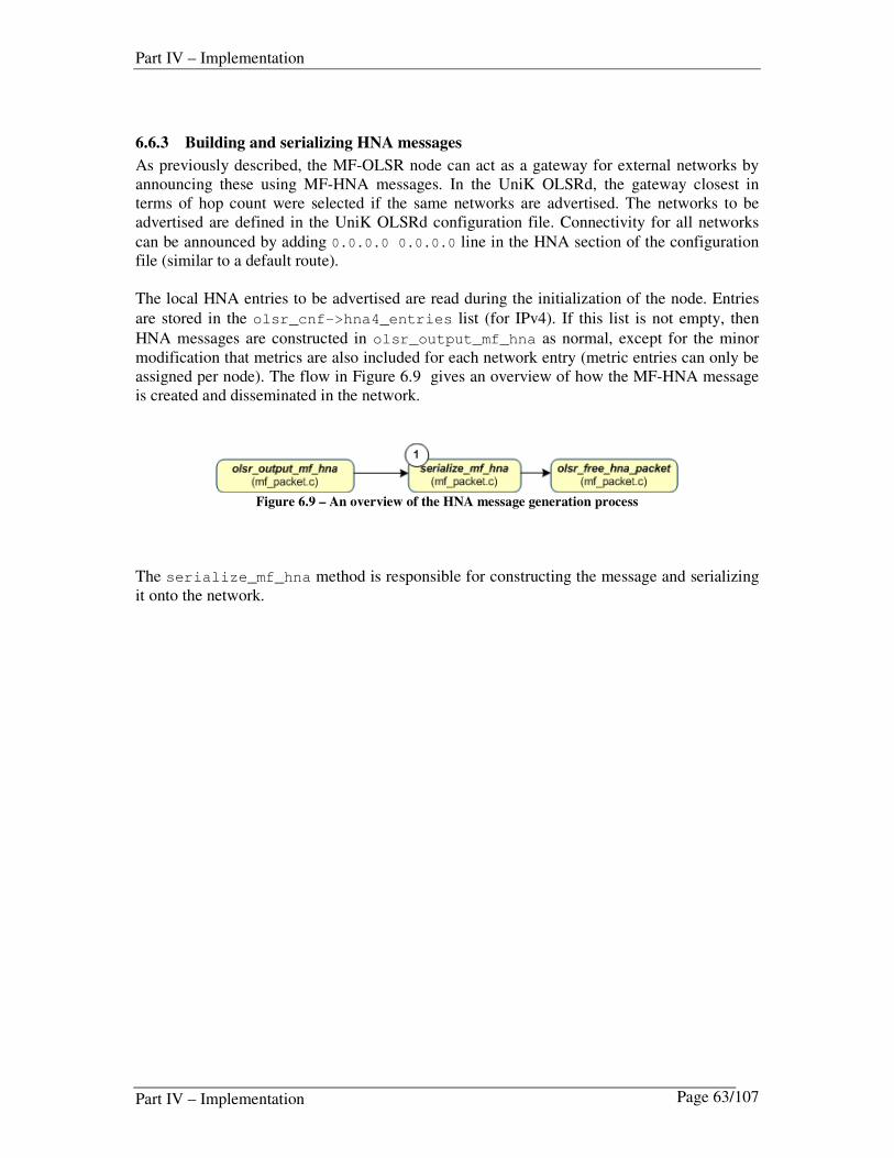
Part IV – Implementation
Part IV – Implementation Page 63/107
6.6.3 Building and serializing HNA messages
As previously described, the MF-OLSR node can act as a gateway for external networks by announcing these using MF-HNA messages. In the UniK OLSRd, the gateway closest in terms of hop count were selected if the same networks are advertised. The networks to be advertised are defined in the UniK OLSRd configuration file. Connectivity for all networks
can be announced by adding 0.0.0.0 0.0.0.0 line in the HNA section of the configuration file (similar to a default route). The local HNA entries to be advertised are read during the initialization of the node. Entries
are stored in the olsr_cnf->hna4_entries list (for IPv4). If this list is not empty, then
HNA messages are constructed in olsr_output_mf_hna as normal, except for the minor modification that metrics are also included for each network entry (metric entries can only be assigned per node). The flow in Figure 6.9 gives an overview of how the MF-HNA message is created and disseminated in the network.
Figure 6.9 – An overview of the HNA message generation process
The serialize_mf_hna method is responsible for constructing the message and serializing it onto the network.

Part IV – Implementation
Part IV – Implementation Page 64/107
6.6.4 Receiving and processing MF-HNA messages
The olsr_input_mf_hna method is registered with the packet parser to handle incoming MF-HNA messages (this is described in chapter 6.3). The most important methods involved in handling incoming MF-HNA messages are outlined below (other MF-OLSR messages are created in a similar matter):
Figure 6.10 - HNA messaging overview
The majority of the work is performed in the deserialize_mf_hna method.
6.6.5 Route re-calculation trigger for HNA routes
A recalculation of the routes will be triggered with the global variable changes_hna. This global variable will change if a new entry is added to the HNA set, or an entry is timed out.
The global variables are processed in the function olsr_process_changes defined in
src/olsr.h for every scheduler poll (by default every 0.1 seconds). If the changes_hna is true then a recalculation is executed.

Part IV – Implementation
Part IV – Implementation Page 65/107
6.7 Printing and debug methods
Troubleshooting and debugging is a time consuming activity. To simplify this process some special purpose printing methods were implemented. Either to display the messages as structured in memory, or before serializing to the network. The main method used to print serialized messages is the following. olsr_8_t print_mf_olsr_serialized_message(FILE *, union olsr_message *);
In addition the following methods were implemented.
/* Methods related to printing serialized packets */
void print_hellomsg_mf(FILE *, olsr_u8_t *, olsr_16_t);
void print_tcmsg_mf(FILE *, olsr_u8_t *, olsr_16_t);
void print_hnamsg_mf(FILE *, olsr_u8_t *, olsr_16_t);
void olsr_print_mf_tc(FILE *handle, struct mf_tc_message *);
void olsr_print_mf_hello(FILE *, struct mf_hello_message *);
void olsr_print_mf_hna(FILE *, struct hna_message *); /*
convert to mf_hna ??*/
const char *mf_olsr_lmt_to_string(olsr_u8_t);
const char *mf_olsr_msgtype_to_string(olsr_u8_t);
const char *mf_olsr_radiotype_to_string(olsr_u8_t);

Part IV – Implementation
Part IV – Implementation Page 66/107
7 The Multihome Plug-in This chapter describes the implementation of the multihome plug-in, the dissemination of the multihoming MF-HNA messages and how mesh nodes select their default gateway.
7.1 Multihoming plug-in files and configuration
The MF-HNA gateway metric type (GWMT) and gateway status value (GWSV) is configured via the multihome plug-in. This plug-in also controls most of the configuration settings for MF-HNA multihoming.
• olsrd_plugin.c
• olsrd_multihome.h
• olsrd_multihome.c
7.1.1 Multihoming plug-in configuration
The behaviour of the multihoming plug-in is controlled in the configuration file. (See the appendix for how to modify the MF-OLSR configuration file). Below is an example configuration that will enable the multihoming plug-in to disseminate metric information of type 16 (GWMT_POWER), with a default value of 10.
LoadPlugin "olsrd_multihome.s0.1"
{
PlParam "GwStatusValue" "100"
PlParam "GwMetricType" "16"
PlParam "GwStatusDiscoInterval" "5"
PlParam "GwStatusUpdateInterval" "60"
}
If the multihoming plug-in is not used, but HNA messaging is enabled, a default gateway status value and metric type is used. The default values for these options are currently DEF_GW_STATUS_VALUE and DEF_GW_METRIC_TYPE. This basically means that if they are not defined manually, no metric-based multihoming will be used.
7.2 Dissemination of multi-homing HNA messages
The dissemination of MF-HNA messages is implemented in the auxiliary functionality of the MF-OLSR extensions. This means that MF-HNA messages will be disseminated if the traditional configuration exists in the MF-OLSR configuration file.

Part IV – Implementation
Part IV – Implementation Page 67/107
7.2.1 Multihoming gateway metrics
The metrics defined for a gateway announcing MF-HNA messages are listed in Table 7-17
Metric Name Metric Value Description
GWMT_NULL 0 Default
GWMT_BW 1 Internet link
GWMT_DELAY 2 Internet link
GWMT_LOAD 4 Node CPU load
GWMT_COST 8 Static value or link
GWMT_POWER 16 Node Powerinfo Table 7-1 - The list of predefined Gateway Metric Types for the multihoming plug-in
7.3 Gateway status discovery
The intervals defined in the configuration file tell the multihome plug-in how often it should try to detect the gateway status. It also defines what type of status to retrieve from the gateway node. The following method is registered with the scheduler to perform gateway status detection.
olsr_register_scheduler_event(&olsr_gw_status_discovery,
NULL,
multihome_param.gw_status_disco_interval, 0, NULL);
The method registered with the scheduler, as a result of the above command, will make the
method listed below run every gw_status_disco_interval.
void olsr_gw_status_discovery(void *foo)
{
OLSR_PRINTF(7, "\nGateway Status Discovery Starting.\n");
switch(multihome_param.gw_metric_type)
{
case(GWMT_NULL):
olsr_retrieve_null_status();
case(GWMT_BW):
olsr_retrieve_bw_status();
case(GWMT_DELAY):
olsr_retrieve_delay_status();
case(GWMT_LOAD):
olsr_retrieve_load_status();
case(GWMT_POWER):
olsr_retrieve_battery_status();
7 These metrics can be used via the configuration file, but are primarily meant to be placeholders for other plugins that dynamically can populate these.

Part IV – Implementation
Part IV – Implementation Page 68/107
default:
break;
}
/* Assign values to the IP nets in HNA configuration. */
assign_metrics_to_local_hna_set(multihome_param.gw_status_value
, multihome_param.gw_metric_type);
OLSR_PRINTF(7, "\nGateway Status Discovery Finished.\n");
}
The assign_metric_to_local_hna_set will make sure that the retrieved values are assigned to the IP nets described in the HNA configuration. Eventually, these are the ones that are disseminated on the network.

Part IV – Implementation
Part IV – Implementation Page 69/107
8 The Airtime Plug-in A large number of routing protocols have been proposed for MANET and MESH networks, e.g. OLSR [23] and AODV [3] (Ad hoc On-demand Distance-Vector). The common denominator is that they all address the problems of route maintenance and topology control. However, few of them consider any lower layer information in this process, e.g., link error, bit rate or contention levels at lower layers. Some proposals on how cross-layer information can be used to calculate an improved path can be found in [24] [16] and [25] In MANETs it has been recognized that, traditional minimum-hop count routing often leads to poor performance due to the distinct characteristics of the wireless medium, and that the focus should be more on the link quality when choosing routes. As a result, minimum-hop-count routing often chooses routes that have significantly less capacity than the best paths that exist in the network. The idea behind the airtime plug-in was to extract some lower-layer wireless information that could be utilized for an improved path calculation. Secondly this metric should be disseminated using the metric-based framework designed in this thesis.
8.1 Operational Overview
The overview provided in Figure 8.1 describes how the airtime plug-in operates. The following chapters provide a more in-depth explanation of the functionality and implementation.
Figure 8.1 - Overview of how the airtime plug-in retrieves lower layer information and converts this to
metric information.
As previously described, the airtime plug-in will extract information needed to calculate the
airtime metric. In Step 1 in Figure 8.1 it is illustrated how the airtime plug-in uses ioctl calls to query information from the network interface. The various methods used are explained in more detail in Chapter 8.3.

Part IV – Implementation
Part IV – Implementation Page 70/107
The lower layer information retrieved in Step 1 is initially stored in the LAB set. This information will be updated and timed out (Step 2), according to predefined values and configuration options in the airtime plug-in configuration. Finally, the airtime metric will be calculated and transferred to the link set. Changes to the link set will trigger route re-calculation using the new metrics. Note that the plug-in requires the MF-OLSR implementation to work. The main reason for this, is that it needs to populate the MetricValue and MetricType attributes implemented in the link set.
8.2 Implementation Overview
In Figure 8.2, the order of execution of the most important airtime plug-in methods are illustrated. The purpose is to provide insight into the methods that are needed to perform the different aspects of the cross-layer design. The different steps in the figure below are marked with numbers. These numbers are referenced and explained further in Chapter 8.3 - 8.4
Figure 8.2 - A flow diagram of how the most important airtime plug-in methods are executed

Part IV – Implementation
Part IV – Implementation Page 71/107
8.2.1 Airtime plug-in files
The following files are included in the airtime plug-in implementation. The files can be found
in the /lib/airtime/ folder of the MF-OLSR distribution. Header file C file Comment
olsrd_plugin.c
olsrd_airtime.h olsrd_airtime.c Main airtime methods (metric calculation)
olsr_arp.h olsr_arp.c ARP methods, arp_cache, get_arp_entry
lab_set.h lab_set.c LAB methods: add, delete, print
Lab_modify.h Lab_modify.c Update LAB entry (main entry)
olsr_spy.h olsr_spy.c Monitoring methods, iwspy, /proc/net/wireless etc.
Table 8-1 - List of files included in the airtime plug-in
Compiling and installing the airtime plug-in is described in the appendix (the general information on compiling and installing UniK OLSRd plug-ins could also be used).
8.2.2 Airtime plug-in configuration parameters
The Airtime plug-in accepts parameters allowing the user to change how it operates. The values for these parameters are kept in the structure airtimeconf_plugin_param, which has the following structure:
struct airtime_plugin_param {
olsr_u16_t link_state_disco_interval;
olsr_u16_t airtime_update_interval;
olsr_bool emulation_mode;
};
8.3 Retrieving lower layer information
There are a number of methods that can be used when trying to extract lower layer information (i.e. bitrates, error information). In general, some of these methods are not very suitable, because they are based on the implementations from specific NIC vendors. Theoretically it could be possible to use a generic network sniffer and extract i.e. bit rate information from the PLCP header for each packet sent to/from a node in the MESH, but this turned out to have several complications that made it difficult to incorporate into the existing plug-in architecture. One such complication was the need to have sniffer software on the node. A second complication was related to how we programmatically could extract this information, and a third complication was related to permissions and interface modes. After some evaluation and prototyping, the method chosen for retrieving wireless statistics and lower layer information, was via the Wireless Extensions API. The reason that this was

Part IV – Implementation
Part IV – Implementation Page 72/107
chosen, is because it provides a common interface towards the different NIC vendor specific drivers.
8.3.1 Using the Wireless Extensions API to retrieve information
The Wireless Extension [20] is a generic API, allowing a driver to expose configuration and statistics specific to common Wireless LANs. The main advantage is that a single set of tool can support all the variations of Wireless LANs, regardless of their type (as long as the driver supports Wireless Extension). Another advantage is that these parameters may be changed on the fly without restarting the driver (or Linux). In the airtime plug-in implementation we mainly use WE to perform two specific tasks. These are related to the initial discovery process and the regular wireless statistics maintenance. For the process of regularly updating information specific for each neighbor, iwspy methods are used. Iwspy was originally designed to test Mobile IP support. It allows the user to set a list of network addresses in the driver. The driver will gather quality information for each of those addresses (updated each time it receives a packet from that address). The tool allows the user to display the information associated with each address in the list. The main method used to retrieve wireless statistics and update the LAB table is outlined below. This method is called from the olsr_retrieve_link_layer_statistics method described in Step 5 in Figure 8.2
struct lab_entry *
update_lab_entry(union olsr_ip_addr *local_ip,
union olsr_ip_addr *neighbor_ip, char *ifname) {
olsr_mac_addr *local_mac, *neighbor_mac;
struct lab_entry *tmp_lab_entry, *entry;
struct iwspy_stats_entry *iwspy_stats;
struct link_entry *link;
float etx;
/* Retrieve local and remote MAC address */
local_mac = (olsr_mac_addr *) olsr_get_if_mac_address(ifname);
neighbor_mac = (olsr_mac_addr *) olsr_arp_query(neighbor_ip,
ifname);
/* Add to the LAB set if not already registered. */
if ( (local_mac!=NULL) && (neighbor_mac!=NULL) ) {
entry = add_new_lab_entry(local_mac, neighbor_mac,
local_ip, neighbor_ip, NEIGHB_HOLD_TIME , ifname);
}
/* An entry was found or created. Let's update the stats. */
if (entry!=NULL) {
/* Retrieve and update iwspy statistics */
if (entry->monitored) {
iwspy_stats = mf_olsr_get_iwspy_stats(neighbor_mac, ifname);
if (iwspy_stats!=NULL) {
entry->iwspy_link_quality= iwspy_stats->iwspy_link_quality;
entry->iwspy_qual_range = iwspy_stats->iwspy_qual_range;

Part IV – Implementation
Part IV – Implementation Page 73/107
entry->iwspy_signal_strength=iwspy_stats->iwspy_signal_strength;
entry->iwspy_signal_noise= iwspy_stats->iwspy_signal_noise;
}
}
link = get_best_link_to_neighbor(neighbor_ip);
if (link) {
entry->error_prob = 1 - link->neigh_link_quality;
// error probability
}
/* Update timestamp */
entry->time = GET_TIMESTAMP(NEIGHB_HOLD_TIME*3000);
entry->update_count++;
/* All attributes are updated , update the airtime */
entry->current_airtime = olsr_calculate_airtime(entry);
}
return entry;
}
8.3.2 ARP query for IP to MAC address resolution
The most important lower layer methods are implemented in olsr_arp.c and olsr_arp.h. An initial problem using ARP cache lookups, was that the entry for the neighboring device was actually non-existing in the ARP cache, also after receiving/sending OLSR control messages. The solution to this challenge, was to send an ICMP packet to the IP address to update the cache. In the initial implementation of the airtime metric plug-in, we will maintain the LAB table using ARP requests, upon receiving control messages. This means that we will perform ARP requests (using ioctl) on each control message sender IP address (for each HELLO interval).
ARP related methods are implemented in the olsr_arp.h / olsr_arp.c files.
Figure 8.3 – An overview of the ARP Cache query solution
The methods that control the dissemination of ICMP echo request packets are listed in Appendix B – code nuggets.

Part IV – Implementation
Part IV – Implementation Page 74/107
8.3.3 Local Link State Discovery phase
The bit rate r and the frame error rate pte are determined during the Local Link State
Discovery phase. The procedures for local link state discovery and maintenance are described in [13], and an adaption to MF-OLSR is outlined below. The local link discovery phase is a recurring procedure to detect the current bit rate in use (modulation mode / receive signal strength indicator), and packet error rate (PER)8 from the links in use. This means that we would need to maintain some statistics for the pair wise links in use. This information is stored in the Local Association Base set. In the structure below we store the values retrieved every time the Link State Discovery process is running. We store the available bit rate and the probability of packet loss during transmission of a standard frame (packet loss is calculated using either ETX or link quality or some other method not yet defined in this draft).
The local link state discovery method called olsr_retrieve_link_layer_statistics is registered with the packet parser and triggered when receiving OLSR control messages. Data is retrieved and the local link set is updated accordingly (with the calculated metric information). Information in the local link set is then advertised as normal using HELLO and TC messages. By implementing the simple procedure above, we have a working solution for retrieving and advertising the metrics in the OLSR domain.
The link_state_discovery_timout method is registered as a timeout function for cleaning out obsolete entries in the local association base. The method is triggered every
LINK_STATE_DISCO_INTERVAL interval.
8 In this draft implementation we will use a simpler method for measuring link quality.
Part IV – Implementation
Part IV – Implementation Page 75/107
8.4 Airtime metric calculation
An important task for the airtime plug-in is to use the retrieved information to calculate the airtime metric and populate the link set with this information. This chapter provides more details on how the metric attributes are stored and calculated.
8.4.1 Airtime Metric Parameters
All attributes necessary to calculate the airtime metric is stored in the airtime_entry structure.
struct airtime_entry
{
struct timeval timer; /* Validity time */
olsr_u16_t bitrate;
olsr_u16_t error_prob;
struct airtime_constants constants;
struct airtime_metric_entry *next; /* Next element */
struct airtime_metric_entry *prev; /* Previous element */
};
During the initialization of the airtime plug-in, the radio type will be detected (currently only
802.11a or 802.11b/g radios will be detected). In olsrd_plugin_init() the method
get_airtime_constants is executed to retrieve these values and fill the struct below.
struct airtime_constants
{
olsr_u16_t ca_overhead;
olsr_u16_t p_overhead;
olsr_u16_t bits_in_testframe;
}
If no values can be retrieved automatically these values will be retrieved from the airtime plug-in configuration section in the MF-OLSR configuration file. If nothing is configured for these settings - default values will be assigned.
8.4.2 Link Quality as error probability
The implementation of error probability calculation is not described in the 802.11s draft paper. It is left for the developer to decide how to implement this feature. In this implementation of the airtime plug-in, we will use an existing feature in the UniK OLSRd implementation called ETX, as the estimation of packet loss for the link. The value 1 / (NLQ x LQ) is called the Expected Transmission Count or ETX. Instead of using this as the metric we use 1 – (NLQ x LQ) as the error probability. In a situation where we two packets are lost in each direction between two nodes the error probability would be estimated as; 1 – (0.8 x 0.8) = 36%

Part IV – Implementation
Part IV – Implementation Page 76/107
8.5 Local Association Base (LAB)
The Local Association Base (LAB) will keep track of the MAC addresses of all associated nodes (this is similar to the description in the 802.11s draft). This set will be similar to the existing link set, but it will keep the MAC addresses instead of the IP addresses. There are no limitations to the number of nodes to be kept in the LAB set, but there is currently a limitation on the number of nodes that can be monitored using iwspy9 . The LAB set will always contain the same entries as in the Link Set. Based on specific intervals and triggers, the airtime metric value is calculated and populated to the link set. From the link set these values will be distributed using MF-HELLO/MF-TC messages as normal. The airtime plug-in will mainly operate on the LAB set. It will be responsible for calculating the airtime metric, updating the link set and also adding/removing entries form the LAB set.
8.5.1 The LAB entry
The LAB table contains information on the currently associated hosts. The LAB table is updated every time an MF-OLSR control message is received, or whenever the plug-in decides that an update should occur. A LAB entry is timed out similar to how link set entries
are timed out. LAB related methods are implemented in src/lab_set.c
struct lab_entry {
olsr_mac_addr *neighbor_mac_addr; // 6-byte address
olsr_mac_addr *local_mac_addr; // 6-byte address
union olsr_ip_addr *neighbor_ip_addr;
union olsr_ip_addr *local_ip_addr;
char *ifname;
olsr_u32_t iwspy_signal_strength;
olsr_u32_t iwspy_noise_level;
olsr_u32_t iwspy_link_quality;
olsr_u16_t bitrate; // i.e RSSI
olsr_u16_t error_prob;
olsr_u32_t airtime;
};
lab_set lab_entry[MAX_LAB_ENTRIES];
9 iwspy can only monitor eight addresses.

Part IV – Implementation
Part IV – Implementation Page 77/107
The table below contains an example of how the local association base would look like if we had some neighbors and several local interfaces.
local MAC local IP neig. MAC neig. IP airtime quality signal noise mon. ifn 00-ff-1b-12-43-11 10.30.1.1 00-ef-ab-e2-43-41 10.30.1.2 1600 67 -65 -10 1 ath0
00-ff-1b-12-43-11 10.30.1.1 30-af-ab-12-43-11 10.30.1.3 1402 68 -66 -23 1 ath0
00-ff-1b-12-43-11 10.30.1.1 40-af-ab-12-43-11 10.30.1.4 1546 48 -75 -21 1 ath0
00-ff-1b-12-43-11 10.30.1.1 60-af-ab-12-43-11 10.30.1.6 1854 58 -65 -19 1 ath0
04-fa-11-12-11-11 10.30.1.5 70-af-ab-12-43-11 10.30.1.7 2356 66 -55 -22 1 ath1
04-fa-11-12-11-11 10.30.1.5 80-af-ab-12-43-11 10.30.1.8 900 62 -45 -27 1 ath1
Table 8-2 - LAB set example
8.5.2 LAB Set implementation
The basic features of the LAB set are implemented as a part of the MF-OLSR core
implementation in the files mf_lab_set.c and mf_lab_set.h. The available methods are;
struct lab_entry *
get_lab_set(void); /* Return the lab set content */
void
olsr_init_lab_set(void); /* Initialize the lab set */
void
olsr_print_lab_set(void); /* Print the lab set */
The additional features of the LAB set are implemented as a part of the airtime plug-in in the
files mf_modify_lab.c and modify_lab.h. The available methods in these files are
/* Main entry point for adding/updating entries in the LAB Set. */
struct lab_entry *
update_lab_entry(union olsr_ip_addr *, union olsr_ip_addr *, char *);
/* Maintains the LAB set by deleting out-timed entries. */
static void
olsr_time_out_lab_set(void);
/* Retrieve the current airtime value */
olsr_u16_t
olsr_calculate_airtime(struct lab_entry *);

Part V - Tests and conclusions
Part V – Tests and conclusions Page 78/107
Part V – Tests and conclusions This part presents firstly the tests conducted based on the codes implemented in this thesis. The tests are performed based both on a PC-based emulator OLSR_Switch and a real-life test-bed composed of seven laptops. Finally, conclusions on the test results are described.
9 Tests and results This chapter provides information on the performed testing and the achieved results.
9.1 Testbed equipment
The testing equipment consisted of several laptops provided by UniK and additional laptops/stationary hosts provided by a 3rd party. A total of seven hosts were used in the different test scenarios.
9.2 Tests and observed results
The testing for the MF-OLSR code was concentrated on the three topics listed below:
1. “Proof-of-concept” (basic code verification). 2. Convergence based on simple mobility scenario. 3. Convergence based on variations in link load.
The following chapters provide more background and the results from each of these scenarios.
9.2.1 Basic functionality testing / proof-of-concept
The basic functionality testing was concerned with testing the basic and extended functionality of the modified routing protocol. The purpose was simply to make sure that nothing important was broken. Initially, the testing was performed using three hosts, A, B and C, connected such that B could connect to A and C, but A and C could not hear each other. This setup made it possible to test how the routing daemon handled all the new message types MF-HELLO, MF-TC and MF-HNA. Testing was performed with and without the airtime and multihoming plug-ins.

Part V - Tests and conclusions
Part V – Tests and conclusions Page 79/107
Figure 9.1 - Network layout for the basic functionality testing
In the scenario described in Figure 9.1, the behavior was as expected. Traffic from Node C got routed through Node A via Node B. This route was elected using the airtime cost (when the airtime plug-in was enabled) and using hop count when the plug-in was not enabled. When moving the nodes away from each other we could also see how the airtime metric changed related to the current data rate used by the network card driver.

Part V - Tests and conclusions
Part V – Tests and conclusions Page 80/107
9.2.2 Proximity based convergence testing scenario
To verify the correctness and effectiveness of our airtime extension for OLSR, we have considered the following two test scenarios. The first scenario is called the proximity based convergence scenario where the values of the airtime metric vary as the distance between nodes changes. Since the received signal strength varies as the distance between transmitter and receiver changes, the data rate used between these two nodes may change in order to receive the packets correctly. This will lead to a different airtime value with different transmission data rate and frame error probability. As a consequence, a mesh router may choose another node as its gateway, as observed in the scenario in Figure 9.2.
Figure 9.2 - Network layout for testing proximity based route re-calculation for mobile nodes
Figure 9.2 illustrates how the default gateway for Node B changes after moving the node from position 1 to position 2. At point 1, Node B chooses Node A as its default gateway, since the total airtime cost to A is lower. After re-locating to position 2, Node D has been selected as the default gateway, along a path via C. The reason for this change is that the accumulated airtime cost along this path is now lower than that of the direct link to A. In the scenario, this gateway switch is mainly caused by lower data rate on the connection between node A and B when B was moved farther away from Node A. This illustrates how routes can be changed even though the closest gateway in hop count is still available. The node was moved approximately 15 meters in our test.

Part V - Tests and conclusions
Part V – Tests and conclusions Page 81/107
9.2.3 Load-based convergence testing scenario
The purpose of the second scenario was to investigate a load-based convergence situation, where the values of the airtime metric vary as the traffic load of the network changes. For instance, as the traffic load increases, the probability of collision will increase, resulting in different values for the airtime metric. Thanks to the metric-based routing path selection, the network is expected to achieve a balanced load, since some nodes may choose to switch to another less-congested gateway when the airtime path value exceeds a threshold.
Figure 9.3 - Network layout for testing route re-calculation on network congestion / load
Figure 9.3 illustrates the test topology based on the second scenario. It illustrates how routes can be changed when congestion and packet loss occur on a specific link. In this case the congestion took place on Node D. As illustrated in the figure, Node C will, in a hop count based solution, choose Node D as its default gateway, since the total airtime value for this path (C � D) is smaller than that of the other path (C� A). After increasing the traffic load towards gateway Node D by generating traffic from Nodes C, E and F, the routes converged. The traffic types used are ftp and ping, and are monitored using iptraf and tcpdump on the clients. When the generated traffic load increases, the links towards Node D will experience more packet loss, resulting in higher airtime cost. When the accumulated airtime metric value exceeds certain threshold, Node C will re-redirect its traffic towards another gateway, Node A. As a result of this traffic load re-allocation, the total traffic inside this network is fairly balanced among two available gateways.

Part V - Tests and conclusions
Part V – Tests and conclusions Page 82/107
9.3 Parameter optimization for triggering of route re-calculation
Two parameters have been implemented to tune the trade-off between prompt link route re-calculation and path stability. These predefined values that will trigger route re-calculation and airtime metric updates are important for the network stability, thus need to be optimized. Setting a low threshold could make the network converge too often, resulting in unstable routing tables on mesh routers. On the other hand, setting a high threshold will lead to less frequent convergence and a more stable network, but more serious network congestion and higher packet loss.
9.4 Functionality testing using olsr_switch
MF-OLSR functionality testing has been performed mainly using olsr_switch. This is a simulator for running the olsrd. None of the lower layer features can be tested in olsr_switch though. Below are some snapshot of how MF-OLSR looks like when running.
Figure 9.4 – MF-OLSR running in 10 node olsr_switch MF-OLSR network 1/2

Part V - Tests and conclusions
Part V – Tests and conclusions Page 83/107
Figure 9.5 – MF-OLSR running in 10 node olsr_switch MF-OLSR network 2/2
The snapshots are all taken from 10.0.0.1s perspective.

Part V - Tests and conclusions
Part V – Tests and conclusions Page 84/107
10 Conclusions and future work
10.1 Conclusions
In this thesis, a generic framework for metric extensions has been designed, implemented and tested. In addition, I have presented how a cross-layer design based on the airtime metric defined in the 802.11s standard draft can be used in the open source UniK OLSRd implementation, in order to provide an improved load-balanced wireless mesh network with multi-homing. Through implementation and experiments carried out with Linux based test environments, I have demonstrated that the enhanced framework MF-OLSR and the airtime metric-based OLSR network performs properly as designed. Furthermore, through extensive testing, I have proposed how the airtime plug-in parameters can be adjusted for an optimized path selection protocol. In the tests, I have conducted extensive experiments with different parameter settings, in order to find the optimal values for these two parameters. Empirically, the conclusions are that a
triggering value of ~20% (i.e. route re-calculation will be triggered when the change of the accumulated airtime metric values exceeds 20%) and an airtime hold timer equaling to two
HELLO periods provides the best performance for our test network. This results in the link metrics being updated on every data rate signaling change. Furthermore this means that an improved route will be re-calculated and become effective if the current airtime changes beyond the AirtimeTrigger window and the existing route are older than the AirtimeHoldTimer. With the proposed optimal triggering and holding timers, the path selection is able, not only to react properly corresponding to the change of the airtime metric, but also to keep the routes comparatively stable.

Part V - Tests and conclusions
Part V – Tests and conclusions Page 85/107
10.2 Major contributions of this thesis
The major contributions of this thesis are summarized in this section, as follows. MF-OLSR (Metric-based Framework OLSR) – The MF-OLSR implementation is a major contribution of this thesis. This is a generic framework for disseminating metric information in the OLSR domain designed, implemented and tested as a part of this thesis. The design involved changing the original packet formats for HELLO and TC messages, and therefore resulted in rewriting major parts of the current UniK OLSRd implementation. Although airtime metric has been used as the parameter throughout the thesis work, the implemented MF-OLSR does generally support any other metric. The MF-OLSR implementation acts as the foundation for the additional contributions of this thesis. These additional contributions are described below. Airtime/Cross-layer design: Airtime metric path selection and parameter retrieving – Although airtime metric is defined as a default metric in 802.11s, the standard does not specify any mechanisms on how this metric can be implemented. In this thesis, the methods for retrieving and utilizing the airtime metric have been designed, implemented and tested. The solution is based on a cross-layer design where information is retrieved from the network card drivers via the wireless extensions API. This cross-layer functionality has been implemented primarily in the airtime plug-in. The airtime plug-in is the first plug-in that utilizes the framework-based OLSR implementation for disseminating metric information. In the cross-layer design a new repository called LAB (local association base) has been designed and implemented. This repository maintains a list of the associated neighbors and their corresponding MAC address and some wireless statistics. The purpose of this set is to utilize the wireless statistics to each neighbor, for metric calculation. Multihoming with load balancing – For the multihoming scenarios, a new plug-in was designed, implemented and tested. In addition to this new plug-in, the MF-HNA packet format was designed and implemented. The MF-HNA message format adds the capability for a node to include a metric for the announced network. The purpose of the previously mentioned plug-in is to control the dissemination and metric information contained in the MF-HNA messages. This has proven to be very useful for directing traffic through the most suitable gateway. Testing and optimal parameter value adjustments - In addition to the new functionality introduced in MF-OLSR and the accompanying plug-ins, extensive testing in a live Linux based test environment was performed in this thesis. The design and setup of this test environment was time consuming, but gave the ability to test the implementation in a real network. As a result, the testing made it possible to tune and adjust airtime plug-in parameters to achieve the best possible results as a trade-off between route stability and optimized path. Finally, to the best of the authors’ knowledge, the airtime metric work presented in this thesis is the first implemented approach including both airtime based path selection, airtime value retrieving and metric value adjustment.

Part V - Tests and conclusions
Part V – Tests and conclusions Page 86/107
10.3 Future Work
There is still work to be done related to the interoperability with different wireless drivers on different platforms, mainly due to the lack of standardization on how the network drivers interpret and present lower layer information to the user level. Furthermore, the tests performed in this paper are based on realistic, however small-scale test-bed networks. More tests and possibly further improvements need to be done based on real-life large-scale mesh networks. Some suggestions for future work (and development optimization) are;
• Embedding the software in other Linux based appliances (handhelds etc.)
• Investigate more separation between OLSRd and MF-OLSR.
• Airtime plug-in for Windows (different method to retrieve data must be defined).
• Move more code to the plug-in framework.
• Isolate the Layer 2 features and make them more faults tolerant.

References
References Page 87/107
References [1] T. Clausen and P. Jacquet, "Optimized Link State Routing Protocol (OLSR)," in
RFC3226 IETF: IETF, 2003. [2] R. Ogier, F. Templin, and M. Lewis, "Topology dissemination based on reverse-path
forwarding (TBRPF) " in RFC 3684, 2004. [3] C. Perkins, E. Belding-Royer, and S. Das, "Ad-hoc on-demand distance vector
(AODV) Routing," in RFC 3561, 2003. [4] T. Clausen, P. Jacquet, and C. Dearlove, "The Optimized Link State Routing Protocol
version 2," in draft-ietf-manet-olsrv2-05, 2008. [5] C. Perkins, E. Belding-Royer, and S. Das, "RFC 3561 - Ad hoc On-demand Distance
Vector Routing," 2003. [6] IEEE, "Dynamic MANET On-demand (DYMO) Routing, draft-ietf-manet-dymo-13,"
April 10 2008. [7] I. Group, "Draft IEEE P802.11s TM/D1.00," in LAN/MAN Specific Requirements -
Part 11: Wireless Medium Access Control (MAC) and physical layer (PHY)
specifications: Amendment: ESS Mesh Networking New York: IEEE, 2006, p. 243. [8] M. Bahr, "Update on the Hybrid Wireless Mesh Protocol of IEEE 802.11s," in Mobile
Adhoc and Sensor Systems (MASS), 2007, pp. 1-6. [9] Wikipedia, "List of ad-hoc routing protocols," 2007. [10] L. Viennot, "Complexity results on election of multipoint relays in wireless networks,"
in Technical Report: INRIA, 1998, p. 12. [11] T. Clausen, C. Dearlove, J. Dean, and C. Adjih, "Generalized MANET
Packet/Message Format," in draft-ietf-manet-packetbb-08.txt, 2007. [12] T. Clausen, J. Dean, and C. Dearlove, "MANET Neighborhood Discovery Protocol,"
in Internet-Draft, 2008. [13] S. J. Kerry, A. Petrick, and H. Worstell, "Draft IEEE P802.11s TM/D1.00," in
LAN/MAN Specific Requirements - Part 11: Wireless Medium Access Control (MAC)
and physical layer (PHY) specifications: Amendment: ESS Mesh Networking New York: IEEE, 2006, p. 243.
[14] G. R. Hiertz, S. Max, R. Zhao, D. Denteneer, and L. Berlemann, "Principles of IEEE 802.11s," in Computer Communications and Networks, 2007. ICCCN 16th, 2007, pp. 1002-1007.
[15] M. Bahr, "Proposed Routing for IEEE 802.11s WLAN Mesh Networks," WICON'06,
2006. [16] X.-J. Zhu and G.-S. Kuo, "A Cross-Layer Routing Scheme for Multi-Channel Multi-
Hop Wireless Mesh Networks," in CCNC 2008, 5th IEEE, 2008, pp. 927-932. [17] ANSI/IEEE, "802.11a High-Speed Physical Layer in the 5Ghz band " in Wireless
LAN Medium Control (MAC) and Physical Layer (PHY) Specifications. vol. Part 11: IEEE, 1999.
[18] ANSI/IEEE, "802.11b - Higher-Speed Physical Layer Extension in the 2.4Ghz band " in Wireless LAN Medium Control (MAC) and Physical Layer (PHY) Specifications. vol. Part 11: IEEE, 1999.
[19] ANSI/IEEE, "802.11g - Amendment 4: Further High Data Rate Extension in the 2.4 Ghz Band," in Wireless LAN Medium Access Control (MAC) and Physical Layer
(PHY) specifications. vol. Part 11, 2003.

References
References Page 88/107
[20] J. Tourrilhes, "Wireless Tools / Extensions, Available: http://www.hpl.hp.com/personal/Jean_Tourrilhes/Linux/Tools.html," 1996-2008.
[21] A. Tønnesen, "Implementing and extending the optimized link state routing protocol," in UNIK. vol. Master Oslo: UiO, 2004, p. 157.
[22] A. Tønnesen, A. Hafslund, and Ø. Kure, "The UniK OLSR plugin library," in OLSR
Interop and Workshop, 2004. [23] T. Clausen and P. Jacquet, "Optimized Link Statue Routing Protocol (OLSR)," in
RFC3226 IETF: IETF, 2003. [24] J. Sangiamwong and T. Sugiyama, "Hidden Node Problem Aware Routing Metric for
Wireless Mesh Networks," in PIMRC 2007, IEEE 18th Internationl Symposium, 2007, pp. 1-5.
[25] R. de C. Paschoalino and E. R. M. Madeira, "A scalable Link Quality Routing Protocol for Multi-radio Wireless Mesh Networks," in ICCCN, 2007.
[26] T. Farnham, M. Sooriyabandara, C. Efthymiou, M. Wellens, J. Riihijarvi, K. Rerkrai, and M. Bandholz, "Generic Open Link-Layer API for Unified Meda Access - GOLLUM," IST D3.4, Aug.30 2006.

References
References Page 89/107
Index 802.11a.................................................. 21 802.11b ................................................. 21 802.11g ................................................. 22 802.11n ................................................. 22 DYMO ..................................V, 11, 18, 88 ETX ............................. 28, 41, 75, 76, 106 HNA 12, 13, 16, 27, 31, 32, 39, 40, 45, 46,
47, 51, 63, 64, 65, 66, 68, 79, 86, 93, 104, 105, 106
HWMP.................................................. 20 IEEE 802.11s ........................................ 18 iwspy...........23, 41, 48, 72, 73, 77, 94, 101 LAB ...................................................... 41 Link Metric Type ................................... 38 Link Metric Value.................................. 38 LQ.. 28, 31, 34, 35, 51, 52, 54, 76, 92, 104,
106
MANET. III, 10, 11, 14, 15, 16, 18, 28, 33, 70, 88
Mesh......................................................18 MF-HELLO...........................................36 MF-TC...................................................38 MoreMetrics ..........................................38 MPR ........... 15, 16, 26, 27, 36, 58, 60, 105 Multipoint Relays ..................................14 OLSR.....................................................12 OLSRv2...................................... V, 16, 17 PLCP .....................................................72 RA-OLSR..............................................20 RREP.....................................................18 RREQ ....................................................18 TLV.......................................................16 WE ........................................................23

Appendices
Appendices Page 90/107
Appendices
Appendix A – Compilation and Usage Information This appendix contains information on how to retrieve, compile and use MF-OLSR and the addition plug-ins. The latest MF-OLSR codebase can be retrieved using a subversion client by issuing the command;
svn co http://olsr.pgs.com/repos/olsrd-0.5.3
If the subversion service is not available the package can also be downloaded from http://www.velocitynetworks.org/olsr/) If asked for authentication, the username and password is olsr. Methods for compiling the MF-OLSR daemon is similar to those provided with the original OLSRd version. For extensive instructions please read the README document. In most situations it should be adequate to run the following commands (after moving into the eolsrd-0.5.3 folder).
make all
make install
Enabling the Metric Framework
The Metric Framework is enabled by adding the following parameters in the olsrd configuration file (recommended settings).
MetricFrameworkLevel 2
LinkQualityLevel 0
UseHysteresis no
Enabling the metric framework will also assign (and enable) the LinkQualityLevel parameter the same value. This is mainly due to compatibility issues with the original olsrd implementation, but also because similar functions are used by both extensions. Hysteresis can not be used in combination with the metric framework.

Appendices
Appendices Page 91/107
Command line parameters Some additional command line parameters have been defined for MF-OLSR. Information on the original OLSRd parameters can be found in [21] .
usage: olsrd [-f <configfile>] [ -i interface1 interface2 ... ]
[-d <debug_level>] [-ipv6] [-multi <IPv6 multicast addr>]
[-lql <LQ level>] [-lqw <LQ winsize>]
[-mfl <MF level>] [-mfw <MF winsize>]
[-gwsv <GW Status Value>] [-gwmt <GW Metric Type>]
[-bcast <broadcastaddr>] [-ipc] [-dispin] [-dispout] [-delgw]
[-hint <hello interval (secs)>] [-tcint <tc interval (secs)>]
[-midint <mid interval (secs)>] [-hnaint <hna inter. (secs)>]
[-T <Polling Rate (secs)>] [-nofork] [-hemu <ip_address>]
Additional parameters used in MF-OLSR are outlined in bold. Assigning cost to network interfaces Assigning cost to an interface can be done in the interface configuration section. The default cost value will be assigned depending on the network/radio type.
Interface "ath0" "ath1"
{
Cost 30
. . . .
}
Metric values for the metric type we would like to use for route calculation should primarily be automatically detected usually by investigating layer 2 attributes (i.e. for retrieving metrics like residual bandwidth, delay and load). In some cases where it is not possible to automatically detect these values we could define some of them manually. If no value is defined, we have to use the third option, which is a predefined value for the metric we need to use. The cost and bandwidth value can be statically configured under the interface section in the configuration file. If the cost value is not configured, one will be derived either based on the interface bandwidth or a default value. An example is given below: The valid values for the cost metric are between MIN_IF_COST and MAX_IF_COST. If USE_COST_METRIC is enabled, but we are unable to determine the proper metric, the default cost value will be configured as DEF_IF_COST.

Appendices
Appendices Page 92/107
Multihome plug-in usage information The multihome plug-in can be used to populate specific metrics in the HNA messages. The type of metric to be populated, and the value of this metric, can be defined in the OLSRd configuration file.
• Build and install the Multihome plug-in using the command make install (from the
multihome folder)
LoadPlugin "olsrd_multihome.so.0.1"
{
PlParam "GwStatusValue" "10"
PlParam "GwMetricType" "1"
PlParam "GwStatusDiscoInterval" "10"
PlParam "GwStatusUpdateInterval" "15"
}
Httpinfo+ plug-in usage information The httpinfo+ plug-in can be used to get a web based view of the various information repositories. The original httpinfo was developed in UniK OLSRd. This is only an extended version.
• Build and install the httpinfo+ plug-in using the command make install (from the
httpinfo+ folder)
LoadPlugin "olsrd_httpinfo.so.0.1"
{
PlParam "port" "8082"
PlParam "Net" "10.0.0.0 255.0.0.0"
PlParam "Net" "192.168.0.0 255.255.0.0"
}

Appendices
Appendices Page 93/107
Airtime plug-in usage information The single most important criteria for running the airtime plug-in are that you must be running a Linux distribution (current version is developed and tested on Red Hat). The reason for this is the wireless extensions used in the implementation. In future version, other means of retrieving wireless statistics could make the airtime plug-in capable of running on other platforms as well.
• Build and install the Airtime plug-in using the command make install (from the
airtime folder)
• Let MF-OLSRD load the AIRTIME plug-in at start-up, and specify the plug-in parameters (all parameters is seconds, except for MetricUpdateTrigger, which is assigned in percent). The following parameters are possible in the olsrd.conf file:
LoadPlugin "olsrd_airtime.so.0.1"
{
PlParam “LinkStateDiscoInterval” “2”
PlParam “AirtimeupdateInterval” “2”
PlParam “MetricUpdateInterval” “6”
PlParam “MetricUpdateTrigger” “20”
}
• Make sure that the wireless extensions and the wireless tools (iwspy) are available.
• If no plug-in parameters are provided, default values will be used.
• The airtime plug-in can only run on the Linux platform (dependency on wireless tools) and is currently only tested on the Red Hat platform.
Warning! Enabling Airtime Metric breaks compliance with the RFC3226. Airtime Metric enabled nodes do not inter-operate with nodes that have Airtime Metric switched off. Warning! Airtime plug-in uses Jean Tourrilhes Wireless Extensions. These are included in most Linux kernel distributions.
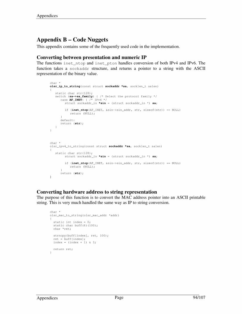
Appendices
Appendices Page 94/107
Appendix B – Code Nuggets This appendix contains some of the frequently used code in the implementation.
Converting between presentation and numeric IP The functions inet_ntop and inet_pton handles conversion of both IPv4 and IPv6. The
function takes a sockaddr structure, and returns a pointer to a string with the ASCII representation of the binary value.
char *
olsr_ip_to_string(const struct sockaddr *sa, socklen_t salen)
{
static char str(128); switch (sa->sa_family) { /* Select the protocol family */
case AF_INET: { /* IPv4 */
struct sockaddr_in *sin = (struct sockaddr_in *) sa;
if (inet_ntop(AF_INET, &sin->sin_addr, str, sizeof(str)) == NULL)
return (NULL);
}
default: return (str);
}
}
char *
olsr_ipv4_to_string(const struct sockaddr *sa, socklen_t salen)
{
static char str(128);
struct sockaddr_in *sin = (struct sockaddr_in *) sa;
if (inet_ntop(AF_INET, &sin->sin_addr, str, sizeof(str)) == NULL)
return (NULL);
} return (str);
}
Converting hardware address to string representation The purpose of this function is to convert the MAC address pointer into an ASCII printable string. This is very much handled the same way as IP to string conversion.
char *
olsr_mac_to_string(olsr_mac_addr *addr)
{
static int index = 0;
static char buff(6)(100);
char *ret;
strncpy(buff[index], ret, 100);
ret = buff[index];
index = (index + 1) & 3;
return ret;
}

Appendices
Appendices Page 95/107
Sending ICMP echo requests These methods are responsible for updating the local ARP cache with valid information on the existing OLSR neighbors. Some of the text might be truncated.
struct olsr_mac_addr *
olsr_arp_query(union olsr_ip_addr *ip, char *ifname)
{
…..
/* Allocate memory for arp result */
mac = olsr_malloc(MAC_ADDR_SIZE,"ARP resolver");
/* Create a socket to communicate with the kernel */
sockfd = socket(AF_INET, SOCK_DGRAM, 0);
/* Prepare the Protocol Address part -> arpreq .arp_pa */
memcpy(&sin.sin_addr, ip, olsr_cnf->ipsize);
sin.sin_family = AF_INET;
/* Prepare the Hardware Address Placeholder -> arpreq.arp_ha */
memset(&arp_query, 0 , sizeof(struct arpreq));
memcpy(&arp_query.arp_pa, &sin, sizeof(struct sockaddr_in));
strncpy(arp_query.arp_dev, ifname, IFNAMSIZ); /* specify interface name */
if( ( ioctl(sockfd, SIOCGARP, &arp_query) < 0) ||
!(arp_query.arp_flags & ATF_COM)) /* ATF_COM - hw addr valid */
{
OLSR_PRINTF(1, " +ARP failed: (%s) - trying lookup\n", strerror(errno));
/* No address - create a thread that sends a PING */
send_ping(ip);
return NULL;
}
memcpy(mac, &arp_query.arp_ha.sa_data, MAC_ADDR_SIZE);
close(sockfd);
OLSR_PRINTF(9," +ARP Success -> %s\n", olsr_mac_to_string(mac));
return mac;
}
void
send_ping(union olsr_ip_addr *ip)
{
int ping_s;
struct sockaddr dst;
struct sockaddr_in *dst_in;
char *packet;
struct icmphdr *icp;
dst_in = (struct sockaddr_in *) &dst;
dst_in->sin_family = AF_INET;
memcpy(&dst_in->sin_addr, ip, olsr_cnf->ipsize);
if ((ping_s = socket(AF_INET, SOCK_RAW, PF_INET)) < 0) {
OLSR_PRINTF(1, "Could not create RAW socket for ping!\n%s\n", strerror(errno));
return;
}
/* Create packet */
packet = malloc(MAXIPLEN + MAXICMPLEN);
icp = (struct icmphdr *)packet;
icp->type = ICMP_ECHO;
icp->code = 0;
icp->checksum = 0;
icp->un.echo.sequence = 1;
icp->un.echo.id = getpid() & 0xFFFF;
if((sendto(ping_s, packet, MAXIPLEN + MAXICMPLEN + 8, 0, &dst,
sizeof(struct sockaddr))) != MAXIPLEN + MAXICMPLEN + 8) {
OLSR_PRINTF(1, "Error PING: %s\n", strerror(errno));
}
close(ping_s);
free(packet);
return;
}

Appendices
Appendices Page 96/107
Appendix C – How to modify OLSRd configuration file options This appendix contains a detailed description of how to add configuration options to the Unik OLSRd configuration file. These extensions were needed to provide additional functionality related to the MF-OLSR implementation.
Adding configuration file options to oscan.lex The configuration options that can be used in the configuration file is defined in the scan.lex file. The following lines were added to oscan.lex to achieve the functionality needed in this implementation.
"MetricFrameworkLevel" {
yylval = NULL;
return TOK_MF_LEVEL;
}
"MetricFrameworkDijkstraLimit" {
yylval = NULL;
return TOK_MF_DLIMIT;
}
"MetricFrameworkWinSize" {
yylval = NULL;
return TOK_MF_WSIZE;
} "Cost" {
yylval = NULL;
return TOK_IFCOST;
}
Defining default values and attributes for additional values Default values are defined in src/olsr_cfg.h
/* Metric Framework */
#define DEF_MF_LEVEL 2
#define DEF_MF_WSIZE 10
#define DEF_MF_DIJK_INTER 0.0
#define DEF_MF_DIJK_LIMIT 255
#define MAX_MF_LEVEL 2
#define MIN_MF_LEVEL 0
#define MIN_MF_WSIZE 3
#define MAX_MF_WSIZE 128
/* Metric Framework */
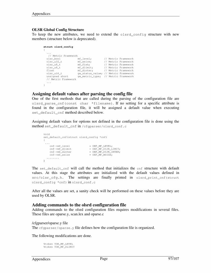
Appendices
Appendices Page 97/107
OLSR Global Config Structure
To keep the new attributes, we need to extend the olsrd_config structure with new members (structure below is deprecated).
struct olsrd_config
{
...
// Metric Framework
olsr_bool mf_level; // Metric Framework
olsr_u32_t mf_wsize; // Metric Framework
olsr_u8_t mf_fish; // Metric Framework
olsr_u8_t mf_dlimit; // Metric Framework
float mf_dinter; // Metric Framework
olsr_u16_t gw_status_value; // Metric Framework
unsigned short gw_metric_type; // Metric Framework
// Metric Framework
...
}
Assigning default values after parsing the config file One of the first methods that are called during the parsing of the configuration file are
olsrd_parse_cnf(const char *filename). If no setting for a specific attribute is found in the configuration file, it will be assigned a default value when executing
set_default_cnf method described below. Assigning default values for options not defined in the configuration file is done using the
method set_default_cnf in /cfgparser/olsrd_conf.c
void
set_default_cnf(struct olsrd_config *cnf)
{
...
cnf->mf_level = DEF_MF_LEVEL;
cnf->mf_dlimit = DEF_MF_DIJK_LIMIT;
cnf->mf_dinter = DEF_MF_DIJK_INTER;
cnf->mf_wsize = DEF_MF_WSIZE;
........
}
The set_default_cnf will call the method that initializes the cnf structure with default values. At this stage the attributes are initialized with the default values defined in
src/olsr_cfg.h. The settings are finally printed in olsrd_print_cnf(struct
olsrd_config *cnf) in olsrd_conf.c After all the values are set, a sanity check will be performed on these values before they are used by OLSR.
Adding commands to the olsrd configuration file Adding commands to the olsrd configuration files requires modifications in several files. These files are oparse.y, scan.lex and oparse.c /cfgparser/oparse.y file
The cfgparser/oparse.y file defines how the configuration file is organized.
The following modifications are done.
%token TOK_MF_LEVEL
%token TOK_MF_DLIMIT

Appendices
Appendices Page 98/107
%token TOK_MF_WSIZE
%token TOK_IFCOST
conf:
| conf block
| conf stmt
stmt:
| amf_level
| amf_dlimit
| amf_wsize
ifstmt: vcomment
| isetcost
isetcost: TOK_IFCOST TOK_INTEGER
{
int ifcnt = ifs_in_curr_cfg;
struct olsr_if *ifs = cnf->interfaces;
PARSER_DEBUG_PRINTF("\tCost: %d\n", $2->integer);
while(ifcnt)
{
ifs->cnf->cost = $2->integer;
ifs = ifs->next;
ifcnt--;
}
free($2);
}
;
amf_level: TOK_MF_LEVEL TOK_INTEGER
{
PARSER_DEBUG_PRINTF("Metric framework level %d\n", $2->integer);
cnf->mf_level = $2->integer;
free($2);
}
;
amf_dlimit: TOK_MF_DLIMIT TOK_INTEGER TOK_FLOAT
{
PARSER_DEBUG_PRINTF("Metric framework dijkstra limit %d, %0.2f\n", $2->integer, $3-
>floating);
cnf->mf_dlimit = $2->integer;
cnf->mf_dinter = $3->floating;
free($2);
}
;
amf_wsize: TOK_MF_WSIZE TOK_INTEGER
{
PARSER_DEBUG_PRINTF("Metric framework window size %d\n", $2->integer);
cnf->mf_wsize = $2->integer;
free($2);
}
;

Appendices
Appendices Page 99/107
Appendix D – Additional Software Details This appendix provides additional information related to the software used to perform testing and/or development in this thesis.
Building and using tcpdump for wireless capture10
The version of tcpdump is important as it seems that older version has limited WLAN features. A newer version is recommended and at least the versions described below. Tcpdump requires the libpcap libraries to be installed, building libpcap could require bison and flex. These packages are widely available. To build libpcap, untar the source package, enter the directory and execute the following commands:
./configure
make
make install
Flex and bison are both built in exactly the same way. You must then ensure that they are in your path before building libpcap. To build tcpdump, untar the source package, enter the directory and execute the following commands
./configure
make
make install
Now tcpdump captures everything in monitor mode, when the interface is set to promiscuous mode. OPTIONS:
-c exit after receiving count number of packets.
-D List the available interfaces to use tcpdump on.
-e Include header link layer information.
-XX Print headers/data, link level header, in hex and ASCII
-vvv
EXAMPLES:
tcpdump –c 10 –w packets.file Capture 10 packets to file.
tcpdump –i ath0 –XX –vvv
10 Currently there is a problem using tcpdump to capture traffic on Madwifi configured interfaces. This is solved in the latest tcpdump versions.

Appendices
Appendices Page 100/107
Basic information on the Wireless Tools (WT) suite Wireless Tools is the reference installation for the Wireless Extensions, and is heavily used when working with wireless interfaces in Linux.
Command Arguments Comment
iwconfig interface i.e wlan0
Will provide details on the physical interface.
iwlist Interface i.e eth0
Scan the wireless networks. List SSID.
iwpriv -all iwpriv can be used to configure/query the private parameters of the wireless network interface. The parameters available will depend on the driver/card combination.
iwspy interface i.e ath0
Extract wireless statistics for a specific destination.
Wireless tools basic command set
Quick Introduction to Kernel Upgrades The development of wireless support for the Linux platform has been tremendous in the last couple of years. It is therefore recommended that Linux kernels and additional wireless tools / extensions are updated to a newer version. As a ground rule, it is currently a good idea to install the latest kernel etc. available. Here is a short and basic description on how to upgrade the kernel (extensive information on this topic can be found on the internet, so it is also recommended to search for information related to your specific operating system).
1. Download the kernel you need (i.e from http://www.kernel.org/ (>= 2.6.18) 2. Unpack and move to the directory where you unpacked the package.
3. make menuconfig (select the features you need especially Wireless features ☺ )
a. If you need to keep the old config do make oldconfig instead (first you must copy the old kernel .configure file to te root of your new kernel src).
4. make bzImage (will create the Kernel Image File)
5. make modules (copies all module files to /lib/modules/x.x.x/
6. cp arch/i386/boot/bzImage /boot/vmlinuz-x.x.x/ (copy image to /boot)
7. cp System.map /boot (copy system.map to boot). 8. Edit the Boot Loader
a. Edit /etc/lilo.conf for if using the LILO boot loader.
b. Edit /boot/grub/grub.conf if using the GRUB boot loader.

Appendices
Appendices Page 101/107
Appendix E – Deliverable D16 ADHOCSYS (FrontPage Only)
Project No. 026548, ADHOCSYS
Deliverable D16
Software implementation, final version
Contractual Date of Delivery to the CEC: Month 18 (May 1st, 2007)
Actual Date of Delivery to the CEC: May 17, 2007
Author(s): Franco Pagliazzo (ed.), Lorenzo Vandoni, Giampietro Zicca, Gian Maria Giani, Matteo Giulini, Stefano Zanoli, Miodrag Mihaljevic, Frank Y. Li, Geir Egeland, Thomas Aure, Oscar Lazaro, Pedro Sanchez, Marco Ravalli, Paolo Bucciol
Participant(s): EMISFERA, HAL, HT, MISANU, UNIK, INNOVALIA, HP, POLITO
Workpackage: WP4 Implementation
Est. person months: 20
Security: Pub.
Nature: P
Version: 1.0
Total number of pages: 175
Abstract:
This deliverable describes the work that has been performed in the whole period of WP4, from 1 November 2006 to 1 May 2007. The objectives of this work package are the implementation of the algorithms specified in WP2 and WP3 for network operation and low-power consumption, testing of these implementations based on small-scale testbeds, and the deployment of the implemented algorithms over the selected hardware platform. This deliverable, D16, produced as the final version of the technical report for WP4, describes the software implementation activities carried out during this period, following the algorithm descriptions and implementation specifications described in D14 and D15. Compared with our work in WP2 and WP3 which is more research oriented, aiming at finding solutions to ADHOCSYS networks, this deliverable deals with more practical issues, i.e. on how these solutions are implemented and how they behave.

Appendices
Appendices Page 102/107
As the final version of this report, all implementation activities in WP4 have been described in details. More specifically, the implementation activities include the following aspects: - implementation of algorithms for auto configuration - implementation of mechanisms for network self healing - deployment of security and authentication mechanisms - implementation of QoS mechanisms and test of multimedia services - implementation of various enhancements to the OLSR routing protocol - implementation of the centralized configurator The deployment of the implemented algorithms over the selected hardware platform has also been performed in the context of WP4, but is described in a separate deliverable, D17. During the past six months for this work package, we have put most efforts on implementation OLSR enhancements, due to their importance in the project. As a result, all OLSR enhancements specified in D14 have been implemented and tested based on small-scal testbeds. Other implementation activities, e.g. security and authentication mechanisms, auto-configuration, and QoS mechanisms have also been performed and corresponding results have been included in this deliverable, whereas a few QoS implementation activities are mainly conducted in the context of WP2 which runs in parallel with WP4 during this period. The above implementation list covers most important aspects for operating an ADHOCSYS network. For instance, the enhancements to OLSR provide better scalability, more reliable routing using multi-homing, optimized routing using load balancing, and power-aware routing, etc. The QoS mechanisms ensure the provided quality of the basic set of services while increasing network efficiency for other types of applications like multimedia services. The security and authentication mechanisms prevent the network from being attacked and allow only authenticated nodes to enter the network. The self healing mechanisms allow the network to quickly react and recover from possible failures. A centralized management tool makes the supervision of the network by fewer people possible and allows the administrator to remotely reset every node with a new default configuration. Another effort has also been made to let the network be more autonomous and automatic when it is installed. This aspect of the project aims at not only allowing an easy management by the network administrator but also making the setup of new nodes simpler and quicker. Through the script developed here, any potential user of ADHOCSYS networks should be able to install nodes without external assistance from the ADHOCSYS consortium. In the end, all implementations have been converted into a software image based on the Linux operating system installed in the ADHOCSYS hardware platform with wireless drivers and extensions. This aspect of the work is covered by deliverable D17. The above features which have been implementation have also been tested based on Linux laptops and small-scale test-beds during WP4. More testing activities have been planned in the context of WP5, based on the pilot ADHOCSYS network deployed in Coggiola, Italy.

Appendices
Appendices Page 103/107
Appendix F – Paper – Load-balancing in Multi-homed OLSR Networks
Abstract—Wireless Mesh Networks used for broadband access
may be equipped with multiple Internet gateways. Using airtime
metric as the main criterion for path selection is an effective
method for achieving load-balancing in such a multi-homed mesh
network. In this paper, we describe how the radio-aware path
selection using airtime as a metric can be implemented in order
to achieve this functionality, based on a modified version of an
open source OLSR implementation. The paper presents both the
principle of this method, its implementation and the testing
results, focusing on the airtime metric functionality deployed in a
small-scale test network.
I. INTRODUCTION
Among various potential application scenarios provided by Wireless Mesh Networks (WMNs) [1], broadband Internet access using WMNs appears as one of the most promising directions for applying this technology. When a WMN is connected to the global Internet, it exhibits great advantages when the WMN is connected via multiple gateways, in terms of achieving both reliability and load balancing. When multi-homed, an end-user can still enjoy network connection if at least one gateway is working. On the other hand, traffic load inside the WMN access network can be kept balanced among different paths and gateways, to avoiding congestion of certain heavily loaded paths or gateways.
Furthermore, a routing protocol must be supported in order to keep a WMN running. Given the fact that the mesh routers are placed in a static topology in typical Internet access scenarios, we are in favor of using a proactive routing protocol for routing purpose in this case. Consequently, Optimized Link State Routing (OLSR) (4) has been selected as the baseline routing protocol in this study.
To achieve load balancing, the path selection from a mesh router to a gateway has to rely on specific metrics. In the legacy OLSR, path selection is purely based on the hop count metric. This will cause multi-homed OLSR networks to route traffic towards the closest gateway, in hop count, even though the path to the gateway or the gateway itself could be congested. It is quite common that traffic is directed via links with lower capacity radio types or higher error rate. None of these factors are considered in the pure hop-count based routing protocols. In addition to the path selection problem,
there is also a challenge when selecting the most appropriate gateway to handle Internet traffic. Problems such as overloaded Internet links or congested CPU might also cause problems for OLSR networks.
In OLSR, gateway availability is advertised by using the Host and Network Association (HNA) messages. If several gateways are announced in the same network, the gateway with the lowest hop count will be elected. To improve the gateway selection, modified HNA messages including various gateway metrics, such as powerinfo, CPU load and the Link Quality (LQ) extension to OLSR (6), have been introduced in several different implementations. The purpose of these extensions was to provide dynamic gateway selection based on specific gateway attributes. However, most of these types of extensions have only considered attributes of the gateway itself, not the overall path towards the gateway.
In this paper, we present the airtime metric introduced in (5) and describe how the airtime metric can be implemented and employed in order to provide an improved load balanced multi-homed OLSR network. The features described in this paper have been implemented as an extensive enhancement to OLSR (3). The enhancement includes the introduction of three new message types, a new local association set and a revision of the route calculation method.
After presenting background information and principle of this OLSR enhancement, we present in details how the airtime metric is implemented, which is based on a popular OLSR implementation (6). The most important parts of our enhancement, i.e. airtime-based path selection, as well as some test results obtained from a test network, are also presented in the paper.
The rest of the paper is organized as follows. Sec. II gives background information on OLSR. Sec. III presents RA-OLSR and the airtime metric. Sec. IV presents MF-OLSR (implemented extensions to the open source OLSR implementation in (6), while Sec. V describes the expected behavior and some test results. Finally, the paper is concluded in Sec. VI.
II. BACKGROUND INFORMATION ON OLSR
Load-balancing in Multi-homed OLSR Networks
using Airtime Metric and Radio-aware Path Selection:
Implementation and Testing
Thomas Aure* and Frank Y. Li‡ *UniK, University Graduate Center, University of Oslo, N-2027 Kjeller, Norway
‡Dept. of Information and Communication Technology, University of Agder, N-4898 Grimstad, Norway
Email: *[email protected]; ‡[email protected]

Appendices
Appendices Page 104/107
A. OLSR BRIEF
OLSR is the most representative proactive routing protocol for ad hoc networking, and it has been extensively studied both in theory and in practice. Inherited from Open Shortest Path First (OSPF), it is a link state protocol, where each router keeps the topology information of the entire network, and the routes to all other nodes are always available, no matter whether there is any ongoing traffic or not.
To minimize protocol overhead introduced by link state protocols, OLSR is built based on the concept of Multipoint Relay (MPR). The MPR of a node is one of its one-hop neighbors that have been selected as the next hop to reach a maximum number of its two-hop neighbors. The node that has selected its MPRs is referred to as an MPR selector. The set of MPRs, which is a sub-set of all one-hop neighbors of the MPR selector, can therefore reach all two-hop neighbors of the MPR selectors.
The optimization of protocol overhead is achieved through the use of MPRs in a distributed network. Firstly, only MPRs with non-empty MPR selectors can generate Topology Control (TC) messages. Secondly, when TC messages are received by a node, only those nodes which are MPRs will further forward TC messages to other nodes inside the same network. Thirdly, an MPR node may choose to report partial link state.
OLSR operates in three main steps:
• Neighbor sensing. This is achieved by exchanging HELLO messages between all one-hop neighbors in a network. Through periodic HELLO messages received from its one-hop neighbors, a node is able to select its MPRs. Then a link state database and a neighborhood database are established by each node based on neighbor sensing.
• TC messages dissemination. Each node, through its MPRs,
periodically advertises its link information to all other
nodes inside the network. As a consequence, all nodes
inside a network have necessary topology information for
all links between any two nodes inside the same network.
• Routing table calculation. Based on TC messages received from other nodes, a node is able to compute its shortest-path routes to all reachable nodes in the network, by using an algorithm similar to the Dijkstra algorithm. According to (4), the shortest-path in terms of the number of hops is used for route calculation in OLSR.
Furthermore, two other messages are defined in OLSR, i.e. Multiple Interface Declaration (MID), and HNA. MID messages are used when a node is equipped with multiple interfaces. However, only one interface is selected as the ID (main address) of the node. HNA messages are used when a node functions as a gateway node, and it is especially useful when an ad hoc network is connected to the Internet. It is worth mentioning that multi-homing is already supported in the legacy OLSR. However the default gateway selection is solely based on hop count to the gateway.
III. RA-OLSR AND AIRTIME METRIC INTRODUCTION
A. RA-OLSR
The RA-OLSR (radio aware OLSR) specification was introduced in the 802.11s mesh networks draft. The original intention was to use RA-OLSR as an optional routing protocol in wireless mesh networks. This feature was however not included in the latest draft (5), because the TGs task group decided to only specify the features of the mandatory protocol in 802.11s, Hybrid Wireless Mesh Protocol (HWMP) (5). However, the proactive features originated from OLSR have been imbedded in HWMP and the airtime metric has been kept for path selection in 802.11s Mesh networks. In the next subsection we give a brief introduction to the airtime metric. B. Airtime Metric
The airtime metric drafted in (5) was developed to provide the path selection protocol, in a mesh network, with an efficient radio-aware path. Airtime reflects the amount of channel resources consumed by transmitting the frame over a particular link. Combing features described in 802.11s (5) with existing features in the OLSR routing protocol gives us a new vision for OLSR. The metric takes into consideration the radio type used, the current data rate and the frame error probability. The following algorithm for airtime metric calculation for each link is defined in (5)
Figure 1 - Airtime metric algorithm.
where O and Bt are constants as listed in Table 1, and the input parameters r and ef are the data rate in Mb/s and the frame error rate for the test frame size Bt respectively. According to (5) Overhead (O) is defined as the combined channel access and protocol overhead, including frame headers, training sequences, access protocol frames, etc.
802.11a 802.11b/g Description
caO 75 sµ 335 sµ Channel access overhead
pO 110 sµ 364 sµ Protocol overhead
tB 8192 8192 Bits in test frame
Table 1: Airtime metric constants.
The values listed in Table 1 are all constants defined in (5).
Description Determined
fe Frame Error Probability
Link State Discovery
r Data rate Link State Discovery
Table 2: Airtime metric variables.
Two other parameters used for airtime calculation are listed in Table 2. The 802.11s standard itself does not specify how the airtime metric is obtained in a mesh network. In the implementation described in this paper, the
frame error rate (error probability) ef is approximated and

Appendices
Appendices Page 105/107
implemented as the ETX (expected transmission count) value as suggested in (9). The data rate r is extracted using the wireless extensions (2) API. This is an open source commonly distributed API that provides a generic driver interface for accessing network interface card information. The radio type detection needed for assigning the constants in Table 1 is also retrieved using this generic API.
C. Airtime based path selection
Based on the airtime metric obtained, a mesh router is able to select a path towards destination with least airtime cost. The figure below illustrates an example on how the airtime metric will provide an efficient path through the network considering the data bit rate, radio type and frame error probability. All airtime metrics given below include the radio type on each link.
Figure 2 : Airtime based path selection example.
As illustrated in the above figure, the shortest path from Node C to Node E would normally be directly through Node D because this is only two hops. However, based on the total path airtime cost between Node C and Node E, the path via Node F and Node G are selected, even though this path has one additional hop. Similarly in the same figure we observe that the preferred path from Node A to Node D is via Node C, despite a direct link between Nodes A and D.
IV. MF-OLSR AND AIRTIME IMPLEMENTATION
In order to support metric-based routing in OLSR, we need to extend existing HELLO, TC and HNA messages to carry out necessary metrics for neighbor, link and topology dissemination. This task has been designed and implemented in a generic framework, referred to as Metric-based Framework (MF) for OLSR, MF-OLSR. The MF-OLSR includes three new messages types, as MF-HELLO, MF-TC and MF-HNA messages. These message types are all capable of carrying single or multiple metric values and metric types. The ability to carry several metrics allows us to deploy both LQ metrics and airtime metrics in the same domain. In other words, the implemented MF-OLSR described in this paper can be used for multiple metrics. The default metric used in MF-OLSR is airtime which is described below.
In the following subsections, we present first the format of the extended messages and then describe how the airtime metric is obtained in our implementation. A few associated aspects are also discussed in this section.
A. Format of the extended OLSR messages
The format of the extended OLSR messages are illustrated in Tables 3-5. These parts are included in the data field in the generic OLSR packet format.
Table 3: Extended HNA message packet format.
Table 4: Extended HELLO message packet format.
Table 5: Extended TC message packet format. B. ETX as frame error probability
In [5] the implementation of error probability is described as a local implementation choice. Obviously, there are several methods that could be used to approximate this value. In this implementation we have decided to use the ETX for this purpose. The ETX values are estimated using the LQ extension featured in OLSR [6]. This will cause the airtime metric to be calculated using cross-layer information. The LQ and NLQ information carried in HELLO messages are exchanged between neighbors and eventually used as the error probability parameter in the airtime metric calculation. This means that the link quality extensions previously distributed in the OLSR domain is now used to measure the quality of a single link. ETX is no longer distributed in TC messages.
Figure 3 : MF-HELLO messaging with Link Quality.
C. Airtime metric based routing
The path selection enhancements described are based on
an optimized routing calculation algorithm, which allows us
to use airtime metrics as the cost value for route
computation. As the input of this algorithm, the airtime
metric of each link within the network is advertised
throughout the whole network, using MF-TC messages, so
that each router has the topology and cost information
needed for its routing calculation. Based upon the airtime

Appendices
Appendices Page 106/107
metric information, a router is able to build its routing table
according to the minimal path cost criterion similar to the
Dijkstra algorithm. This metric-based routing algorithm allows also the use of
multiple metrics at the same time, and to assign a relative weight at each of these metrics. As mentioned earlier, using MF-OLSR for a given network, it is also possible to specify other metrics for path selection. Which metric(s) will be used, as well as its/their relative weight(s), are specified by the network administrator though a configuration file. Based upon this information, each mesh router is able to build its routing table according to the minimal path cost criterion. D. Local Association Base (LAB)
The Local Association Base is adopted from the 802.11s draft. The purpose of the LAB is to contain the MAC layer statistics of each associated neighbour (pairs of MAC addresses). In addition, the LAB set currently contains other attributes needed for airtime metric calculation. The attributes in the LAB set are updated on a regular basis using the wireless extensions API (2). On given intervals, or based on specific criteria, the values in the LAB set will cause the link set to be updated. Finally, after the link attributes are updated this could trigger routing re-calculation.
Figure 4 – Subset of the Local Association Base.
Figure 5 : Airtime information in the LAB set.
Figures 4 and 5 illustrate how a LAB looks like. The values shown in the above figures are extracted from the HTTP+ plugin interface to the developed MF-OLSR daemon presented in this paper [3]. E. Convergence and route stability
The nature of wireless networks is that the link quality is time varying. This presents a challenge to the process of quick detection of new routes and to avoid too many route changes. Hence there is a trade-off between prompt route re-calculation and avoiding situations where the network is unstable due to routes changing too frequently. To control how aggressively we should convert to potentially better routes/links we have defined two configuration parameters, in order to figure out the optimized values which give the best trade-off between prompt route re-calculation and path stability. The first parameter, AirtimeUpdateTriggr, defines how much the airtime metric must have changed in percent before the metric in the MF-OLSR link set is updated with the current airtime metric in the link set (a default value of 20% is used to stabilize the implementation, as explained in Subsection V.D). The second parameter, AirTimeHoldTimer, defines the period of time that must have passed before the airtime metric can be changed (unless connectivity is lost).
The optimized values for these two parameters in a mesh network should be obtained empirically.
V. IMPLEMENTATION, DEPLOYMENT AND TEST RESULTS
To validate the behavior and performance of the implemented OLSR extension, we have conducted a set of testing activities, and the results are summarized in the section. In what follows, the deployment of a test network and the test results will be presented, after a brief introduction to our implementation.
A. Implementation of the MF-OLSR enhancements
The MF-OLSR enhancements described above is based on an open source implementation of OLSR (6), and the implemented codes have been released as an open source available for free downloading at (3).
B. Test scenarios
To verify the correctness and effectiveness of our airtime extension for OLSR, we have considered the following two test scenarios.
The first scenario is called the proximity based convergence scenario where the values of the airtime metric vary as the distance between nodes changes. Since the received signal strength varies as the distance between transmitter and receiver changes, the data rate used between these two nodes may change in order to receive the packets correctly. This will lead to a different airtime value with different transmission data rate and frame error probability. As a consequence, a mesh router may choose another node as its gateway, as observed in the next subsection.
The second scenario is called load-based convergence scenario, where the values of the airtime metric vary as the traffic load of the network changes. For instance, as the traffic load increases, the probability of collision will increase, resulting different values for the airtime metric. Thanks to the metric-based routing path selection, the network is expected to achieve a balanced load since some nodes may choose to switch to another less-congested gateway when the airtime path value exceeds a threshold.
C. Tests configuration and observed results
Based on the implementation described above, a small-scale MF-OLSR test-bed network was set up within the seismic company PGS in Oslo. The entire network contained four mobile OLSR nodes and two additional stationary OLSR nodes with Internet connectivity. Figures 6 and 7 illustrate the tests performed in this network, which correspond to the above described two test scenarios respectively.
Figure 6: Route re-calculation for mobile node. Figure 6 illustrates how the default gateway for Node B changes after moving the node from position 1 to position 2. At point 1, Node B chooses Node A as its default gateway

Appendices
Appendices Page 107/107
since the total airtime cost to A is lower. After re-locating to position 2, Node D has been selected as the default gateway, along a path via C. The reason for this change is that the accumulated airtime cost along this path is now lower than that of the direct link to A. In the scenario, this gateway switch is mainly caused by lower data rate on the connection between node A and B when B was moved farther away from Node A. This illustrates how routes can be changed even though the closest gateway in hop count is still available. The node was moved approximately 15 meters in our test.
Figure 7: Route re-calculation on congestion.
Figure 7 illustrates the test topology based on the
second scenario described about. It illustrates how routes can be changed when congestion and packet loss occur on a specific link.
As illustrated in the figure, Node C chooses Node D as its default gateway, since the airtime value for this path (C � D) is smaller that of the other path (C� D). We then increase traffic load towards gateway Node D by generating heavier and heavier traffic from Nodes C, E and F. The traffic types used are ftp and ping, and are monitored by using iptraf (8) and tcpdump (7) on the clients.
When the generated traffic load exceeds threshold, the links towards Node D will experience more packet loss, resulting higher airtime cost. When the accumulated airtime metric value exceeds certain threshold, Node C will re-redirect its traffic towards another gateway, Node A. As a result of this traffic load re-allocation, the total traffic inside this network is fairly balanced among two available gateways.
D. Parameter optimization for triggering of route re-
calculation
As discussed in Subsection IV.E, two parameters have been set up to test the trade-off between prompt link route re-calculation and path stability. These predefined values that will trigger route re-calculation and airtime metric updates are important for the network stability, thus need to be optimized. Setting a low threshold could make the network converge too often, resulting in unstable routing tables on mesh routers. On the other hand, setting a high threshold will lead to less frequent convergence and a more stable network, but more serious network congestion and higher packet loss.
In our tests, we have conducted extensive experiments with different parameter settings, in order to find the optimal values for these two parameters. Empirically, we conclude that
a triggering value of 20% (i.e. route re-calculation will be triggered when the change of the accumulated airtime metric values exceeds 20%) and an airtime hold timer equaling to two HELLO periods give us the best performance for our test network. This results in the link metrics being updated on every data rate signaling change. Furthermore this means that an improved route will be re-calculated and become effective if the current airtime changes beyond the AirtimeTrigger window and the existing route are older than the AirtimeHoldTimer.
VI. CONCLUSIONS AND FUTURE WORK In this paper, we have presented how a cross-layer
design based on the airtime metric defined in the 802.11s standard draft can be used in an open source OLSR implementation, in order to provide an improved load-balanced wireless mesh network with multi-homing. Through implementation and experiments carried out with Linux-based test-beds, we have demonstrated the airtime metric-based OLSR mesh network performs properly as designed. Furthermore, we have also described how the airtime metric parameters can be adjusted for an optimized path selection protocol.
There is still work to be done related to the interoperability with different wireless drivers on different platforms, mainly due to the lack of standardization on how the network drivers interpret and present lower layer information to the user level. Furthermore, the tests performed in this paper are based on realistic however small-scale test-bed networks. More tests and possibly further improvements need to be done based on real-life large-scale mesh networks.
ACKNOWLEDGMENTS The work presented in this paper is supported by the
European Commission in the context of the FP6 ADHOCSYS (No. IST-2004-026548) project.
REFERENCES
[1] I. F. Akyildiz, X. Wang, W. Wang, “Wireless Mesh Networks: a
Survey”, Computer Networks, Volume 47, No. 4, March 2005, pp. 445-487.
[2] J. Tourrilhes, "Wireless Tools / Extensions, Available: http://www.hpl.hp.com/personal/Jean_Tourrilhes/Linux/Tools.html,", 1996-2008.
[3] MF-OLSR implementation, Available: http://olsr.pgs.com/mediawiki [4] T. Clausen and P. Jacquet, "Optimized Link State Routing Protocol
(OLSR)", IETF RFC 3626, Oct. 2003. [5] IEEE 802.11 WG TGs, “Draft Amendment to Standard IEEE
802.11TM: ESS Mesh Networking”, P802.11sTM /D1.08, Jan. 2008. [6] UniK OLSR daemon software, Available: http://www.olsr.org/ [7] tcpdump, Available: http://www.tcpdump.org/ Linux open source
utility. [8] iptraf, Available: http://iptraf.seul.org/ OSI Certified open source
utility. [9] D. S. J. D. Couto, D. Aguayo, J. Bicket, and R. Morris, "A high
throughput path metric for multi-hop wireless routing," in Proc. ACM Mobicom, San Diego, USA, 2003, pp. 419-434.


![Performance Improvement of Optimized Link State …worldcomp-proceedings.com/proc/p2012/ICW4199.pdfThe Optimized Link State Routing Protocol (OLSR) [4] is developed for MANETs and](https://static.fdocuments.in/doc/165x107/5f44c346a76e207a7171e6e5/performance-improvement-of-optimized-link-state-worldcomp-the-optimized-link-state.jpg)


![Lightweight and Energy-Aware Wireless Mesh Routing for ...staff.ui.ac.id/system/files/users/riri/publication/paper_lukman_inteli... · Optimized Link State Routing (OLSR) [9], and](https://static.fdocuments.in/doc/165x107/5f5c9ae7b5e64a779b3eea85/lightweight-and-energy-aware-wireless-mesh-routing-for-staffuiacidsystemfilesusersriripublicationpaperlukmaninteli.jpg)