
An Ontological Approach to Autonomous Navigational ...
65
An Ontological Approach to Autonomous Navigational Decision Making in Aircraft Systems Paul Vajda A Thesis In the Department of Mechanical, Industrial & Aerospace Engineering (MIAE) Presented in Partial Fulfillment of the Requirements For the Degree of Master of Applied Science (Mechanical, Industrial & Aerospace Engineering) at Concordia University Montréal, Québec, Canada April 2020 © Paul Vajda, 2020
Transcript of An Ontological Approach to Autonomous Navigational ...

An Ontological Approach to Autonomous Navigational
Decision Making in Aircraft Systems
Paul Vajda
A Thesis
In the Department of
Mechanical, Industrial & Aerospace Engineering (MIAE)
Presented in Partial Fulfillment of the Requirements
For the Degree of
Master of Applied Science (Mechanical, Industrial & Aerospace Engineering)
at Concordia University
Montréal, Québec, Canada
April 2020
© Paul Vajda, 2020

Concordia University
School of Graduate Studies
This is to certify that the thesis prepared
By: Paul Vajda
Entitled: An Ontological Approach to Autonomous Navigational Decision Making in
Aircraft Systems
and submitted in partial fulfillment of the requirements for the degree of
Degree of Master of Applied Science (Mechanical, Industrial & Aerospace Engineering)
complies with the regulations of the University and meets the accepted standards with respect to
originality and quality.
Signed by the final Examining Committee:
____________________________________________________ Chair
Dr. W. Xie
__________________________________________ Internal Examiner
Dr. W. Xie
__________________________________________ External Examiner
Dr. F. Naderkhani
________________________________________________ Supervisor
Dr. C. Marsden
Approved by:
_____________________________________________________________ 2020
Waizuddin Ahmed Graduate Program Director
_________________________________________________________________
Amir Asif Dean of Faculty

Abstract
An Ontological Approach to Autonomous Navigational Decision Making in Aircraft Systems
Paul Vajda
Aircraft systems are becoming increasingly complex, and automation increasingly necessary forsafe aircraft operation. Current industry trends are encouraging either a reduction of crew num-bers or complete elimination. After surveying the evolution of aircraft automation systems, pilottasks and situational awareness, we argue that a hurdle to crew reduction is that of autonomousnavigation. In this thesis, we put forth an ontology based approach for defining autonomousnavigational decision making. The ontology is designed to capture elements representing theenvironment in which aircraft operate; the “air environment”. An expert system is then pro-grammed and uses the ontology as its knowledge base. Combining the environmental ontologywith a second one describing a generic air vehicle, the expert system is programmed to makenavigational decisions based on environment, vehicle state and mission. Case studies show thefunctionality of the implementation, and a validation study demonstrates the feasibility of thesolution. The thesis closes by relating it to other research and recently released industry avionicssolutions.

Contents
List of Figures . . . . . . . . . . . . . . . . . . . . . . . . . . . . . . . . . . . . . . . . iii
List of Tables . . . . . . . . . . . . . . . . . . . . . . . . . . . . . . . . . . . . . . . . . v
1 Introduction . . . . . . . . . . . . . . . . . . . . . . . . . . . . . . . . . . . . . . . 1
2 Literature Review . . . . . . . . . . . . . . . . . . . . . . . . . . . . . . . . . . . . 3
2.1 A brief historical background of automation and autonomy in aviation . . 3
2.2 De-crewing and Single Pilot Operations (SPO) . . . . . . . . . . . . . . . 3
2.3 Unmanned Aerial Vehicles (UAV – i.e. un-crewed aircraft) . . . . . . . . . 4
2.4 Situational awareness . . . . . . . . . . . . . . . . . . . . . . . . . . . . . 5
2.4.1 Situational awareness and autonomous cars . . . . . . . . . . . . 6
2.4.2 Situational awareness in the FAA National Airspace System (NAS) 6
2.4.3 The Air Environment vs. the Road Environment . . . . . . . . . 7
2.5 Navigational decision making . . . . . . . . . . . . . . . . . . . . . . . . . 7
2.6 Expert systems in air vehicle autonomous research . . . . . . . . . . . . . 8
2.7 Research objectives . . . . . . . . . . . . . . . . . . . . . . . . . . . . . . . 10
3 Methodology . . . . . . . . . . . . . . . . . . . . . . . . . . . . . . . . . . . . . . 12
3.1 A Taxonomy for Defining the Air Environment . . . . . . . . . . . . . . . 12
3.2 An ontological approach to defining the Air Environment . . . . . . . . . 17
3.2.1 Weather . . . . . . . . . . . . . . . . . . . . . . . . . . . . . . . . 19
3.2.2 Navigational Facilities, Airfields and Airspace . . . . . . . . . . . 20
3.2.3 Air Traffic and Air Traffic Control . . . . . . . . . . . . . . . . . 21
3.2.4 Terrain . . . . . . . . . . . . . . . . . . . . . . . . . . . . . . . . 21
3.3 The Air Vehicle . . . . . . . . . . . . . . . . . . . . . . . . . . . . . . . . . 21
3.4 Establishing Context . . . . . . . . . . . . . . . . . . . . . . . . . . . . . . 22
i

3.5 Decision-making . . . . . . . . . . . . . . . . . . . . . . . . . . . . . . . . 23
3.5.1 Scenario 1: Icing Encounter . . . . . . . . . . . . . . . . . . . . . 24
3.5.2 Scenario 2: Engine Failure . . . . . . . . . . . . . . . . . . . . . 25
4 Implementation . . . . . . . . . . . . . . . . . . . . . . . . . . . . . . . . . . . . . 27
4.1 Ontology . . . . . . . . . . . . . . . . . . . . . . . . . . . . . . . . . . . . 27
4.1.1 The Environment . . . . . . . . . . . . . . . . . . . . . . . . . . 27
4.1.2 The Air Vehicle (aka FlyingBlob) . . . . . . . . . . . . . . . . . 28
4.2 The Route Class . . . . . . . . . . . . . . . . . . . . . . . . . . . . . . . . 28
4.3 Databases . . . . . . . . . . . . . . . . . . . . . . . . . . . . . . . . . . . . 30
4.4 Programming Implementation . . . . . . . . . . . . . . . . . . . . . . . . . 31
4.4.1 The Python Route Class . . . . . . . . . . . . . . . . . . . . . . 32
4.4.2 CLIPSPy – A Python CLIPS Binding . . . . . . . . . . . . . . . 33
5 Results . . . . . . . . . . . . . . . . . . . . . . . . . . . . . . . . . . . . . . . . . . 36
5.1 Scenario 1: Anti-ice activation/de-activation and approach mode . . . . . 36
5.1.1 Departing Burlington (KBTV) . . . . . . . . . . . . . . . . . . . 37
5.1.2 Encountering Icing Conditions . . . . . . . . . . . . . . . . . . . 37
5.1.3 Arrival Into Newport (KEFK) . . . . . . . . . . . . . . . . . . . 39
5.2 Scenario 2: Engine failure . . . . . . . . . . . . . . . . . . . . . . . . . . . 40
5.3 Validation Exercise . . . . . . . . . . . . . . . . . . . . . . . . . . . . . . . 41
5.3.1 Position Determination . . . . . . . . . . . . . . . . . . . . . . . 42
5.3.2 Engine Failure Scenario . . . . . . . . . . . . . . . . . . . . . . . 44
5.3.3 Burlington to Newport Flight . . . . . . . . . . . . . . . . . . . . 46
6 Discussion . . . . . . . . . . . . . . . . . . . . . . . . . . . . . . . . . . . . . . . . 50
7 Conclusion . . . . . . . . . . . . . . . . . . . . . . . . . . . . . . . . . . . . . . . . 52
7.1 Future Work . . . . . . . . . . . . . . . . . . . . . . . . . . . . . . . . . . 52
ii
List of Figures
1 Montreal - Portland pipeline (blue) . . . . . . . . . . . . . . . . . . . . . . . . . . 13
2 Pipeline inspection Air Environment taxonomy . . . . . . . . . . . . . . . . . . . 13
3 Flight situation Venn diagram examples . . . . . . . . . . . . . . . . . . . . . . . 14
4 Montreal - Portland pipeline (sectional chart) . . . . . . . . . . . . . . . . . . . . 15
5 Montreal - Portland pipeline (low altitude en-route chart) . . . . . . . . . . . . . 16
6 NAS airspace structure [45] . . . . . . . . . . . . . . . . . . . . . . . . . . . . . . 17
7 Examples of systems, functionality and state . . . . . . . . . . . . . . . . . . . . . 22
8 Context . . . . . . . . . . . . . . . . . . . . . . . . . . . . . . . . . . . . . . . . . 22
9 Icing context . . . . . . . . . . . . . . . . . . . . . . . . . . . . . . . . . . . . . . 23
10 Decision making question cycle . . . . . . . . . . . . . . . . . . . . . . . . . . . . 24
11 Icing encounter question flow . . . . . . . . . . . . . . . . . . . . . . . . . . . . . 25
12 Engine failure question flow . . . . . . . . . . . . . . . . . . . . . . . . . . . . . . 26
13 Ontology high-level concepts . . . . . . . . . . . . . . . . . . . . . . . . . . . . . . 27
14 Environment concepts . . . . . . . . . . . . . . . . . . . . . . . . . . . . . . . . . 27
15 Air Vehicle concepts . . . . . . . . . . . . . . . . . . . . . . . . . . . . . . . . . . 28
16 Route object properties . . . . . . . . . . . . . . . . . . . . . . . . . . . . . . . . 29
17 Runway object . . . . . . . . . . . . . . . . . . . . . . . . . . . . . . . . . . . . . 29
18 runway15-33 object data properties . . . . . . . . . . . . . . . . . . . . . . . . . . 30
19 Python route class . . . . . . . . . . . . . . . . . . . . . . . . . . . . . . . . . . . 32
20 CLIPS Python integration . . . . . . . . . . . . . . . . . . . . . . . . . . . . . . . 34
21 KBTV to KEFK routing (purple) . . . . . . . . . . . . . . . . . . . . . . . . . . . 36
22 OpenGL render - Climb to 7000 ft departing Burlington . . . . . . . . . . . . . . 37
23 OpenGL render - Icing encounter . . . . . . . . . . . . . . . . . . . . . . . . . . . 38
iii

24 OpenGL render - Sequencing to waypoint LUNFI after passing waypoint PLOTT 39
25 OpenGL render - AV descending below the icing layer passing YISXI . . . . . . . 40
26 OpenGL render - AV diverting to KMVL after an engine failure . . . . . . . . . . 41
27 Cessna Cardinal CE-177-B flown in the validation flights . . . . . . . . . . . . . . 42
28 VK-162 GPS chip . . . . . . . . . . . . . . . . . . . . . . . . . . . . . . . . . . . . 43
29 Setup used in flight . . . . . . . . . . . . . . . . . . . . . . . . . . . . . . . . . . . 43
30 Engine failure scenario initial position . . . . . . . . . . . . . . . . . . . . . . . . 44
31 Blob diverting to KMVL . . . . . . . . . . . . . . . . . . . . . . . . . . . . . . . . 45
32 Cardinal positioned in Burlington ready for departure . . . . . . . . . . . . . . . 46
33 Normal flight (Burlington - Newport [purple trajectory]) . . . . . . . . . . . . . . 47
34 Google Earth GPS & FlightAware overlay . . . . . . . . . . . . . . . . . . . . . . 48
35 Flight track recorded by Vk-162 GPS in Google Earth . . . . . . . . . . . . . . . 48
iv

List of Tables
1 Pipeline inspection Air Environment taxonomy . . . . . . . . . . . . . . . . . . . 17
2 Wind Sub-classes . . . . . . . . . . . . . . . . . . . . . . . . . . . . . . . . . . . . 20
3 Convection Sub-classes . . . . . . . . . . . . . . . . . . . . . . . . . . . . . . . . . 20
4 Icing Sub-classes . . . . . . . . . . . . . . . . . . . . . . . . . . . . . . . . . . . . 20
5 Precipitation Sub-classes . . . . . . . . . . . . . . . . . . . . . . . . . . . . . . . . 20
6 Airport Infrastructure Component Sub-classes . . . . . . . . . . . . . . . . . . . . 20
7 Air Traffic Class . . . . . . . . . . . . . . . . . . . . . . . . . . . . . . . . . . . . 21
8 Weather Data Sources & Formats . . . . . . . . . . . . . . . . . . . . . . . . . . . 30
9 Weather Data Sources & Formats . . . . . . . . . . . . . . . . . . . . . . . . . . . 30
10 SQL Databases . . . . . . . . . . . . . . . . . . . . . . . . . . . . . . . . . . . . . 31
11 Route Object: Protege vs. Python . . . . . . . . . . . . . . . . . . . . . . . . . . 33
12 Video 1 - Aircraft video pilot action descriptions . . . . . . . . . . . . . . . . . . 46
13 Video 1 - Aircraft video pilot action descriptions . . . . . . . . . . . . . . . . . . 46
v

1 Introduction
The history of aircraft automation can be linked to changes in technology, infrastructure andregulation. Innovations in communication and navigation equipment simplified core tasks per-formed by flight crews. The implementation of these innovations required infrastructure such asair route traffic control centers be built, and necessitated updates in airworthiness, training andoperations regulations. A significant impact of automation on aircraft operations has been thereduction of crew numbers, or de-crewing. Technological advances in automated systems havemade it possible to reduce the number of crew required to operate a commercial aircraft from 5in the 1940’s to 2 today. A current focus of the aerospace research and development communityis to develop enabling technologies for single pilot operations (SPO).
Research concerning single pilot operations does not always support the implementation of acompletely un-crewed or autonomous aircraft (excluding remotely piloted aircraft (RPA)). Whileincreased vehicle autonomy is central to SPO, the technological advances are still centered arounda “human-in-the-loop” approach. This implies that the air vehicle interfaces with its environmentthrough human perception and decision making. While pilots obtain their situational dataprimarily through vision, tactile and auditory cues, autonomous vehicles interact with theirenvironment differently from piloted vehicles, with the “machine-environment” interface beingthe primary difference. Research in support of un-crewed air vehicles and their introduction intoa shared airspace must focus on autonomous situational awareness and the interface between thevehicle and the environment in which it operates.
There may be more similarities between autonomous ground and air vehicles than there arebetween SPO aircraft and autonomous air vehicles. Both need to acquire information abouttheir environment without a human interface, process this information, and implement naviga-tional decisions while maintaining awareness of changes in the operational environment. In fact,the environment in which an autonomous air vehicle operates is simpler than the autonomousground vehicle environment, with more regulation, more data available and substantially lessunanticipated activity. In this research, we demonstrate that given the current state of existingtechnologies, the difficulty in attaining a safe fully autonomous aircraft lies in obtaining therequired design assurance level in the integration of existing technologies, rather than in thedevelopement of new and innovative hardware and software.
This thesis investigates the environment in which air vehicles operate; the data that is currentlyavailable to inform the user about the state of that environment; how the data is processed forthe human pilot; and how it could be effectively made accessible to an autonomous air vehicle.Validation is provided through case studies developed for an autonomous vehicle operating in ashared airspace.
This thesis is organized in chapters, where Chapter 1 is the introduction. Chapter 2 is a review ofthe relevant literature that begins in Section 2.1 with a brief history of aerospace vehicle automa-tion and communication/navigation systems. Section 2.2 introduces the concept of “de-crewing”and reviews literature on current research efforts aimed at enabling single pilot operations (SPO).In Section 2.3, the motivation for integrating the un-crewed air vehicle (UAV) into a commonairspace is presented, and the tasks to be performed by autonomous technologies for UAV opera-tion are presented. Section 2.4 introduces the topic of situational awareness and how it manifestsitself differently for piloted aircraft, un-crewed aircraft and autonomous cars. Situational aware-ness is discussed in terms of risk, task, information and automation management. Differencesbetween the ground and air environments are highlighted. The navigational decision-makingprocess that follows from situational awareness is presented in Section 2.5, and a number ofapproaches to the automation of navigational decision-making are presented for the air envi-ronment. Section 2.6 introduces the topic of expert systems in aviation and discusses severalapplications. Chapter 2 concludes with a presentation of the objectives of the study, centered
1

on the use of ontological methods to describe the air vehicle environment, the use of existingdata for the purposes of simulating that environment in a systematic manner, and how to usethat data for navigation. Chapter 3 presents the methodology developed to define the ontologyand build the decision-making system. Chapter 4 discusses how the method is implemented insoftware, and Chapter 5 presents the results of the software validation through case studies for anumber of different flight scenarios. Chapter 6 discusses the research more broadly and Chapter7 concludes and provides suggestions for future work.
�
2

2 Literature Review
2.1 A brief historical background of automation and autonomy in aviation
The concept of “pilot assistance” has existed since the beginning of aviation. In 1898, Sir HiramMaxim filed a patent named "Improvements in Aerial or Flying Machines" in which he describeda system that “counteract[s rolling] by the automatic action of a weighted pendulum which, whenthe machine rolls to one side, cuts the supply of motive fluid from the motor on the side whichis higher and opens wider the supply valve of the motor on the lower side.” [67]. This was fiveyears before the Wright brothers successfully flew their machine in Kitty Hawk, North Carolinain 1903. In 1908, Sir Hiram Maxim published a book named “Artificial and Natural Flight”in which he described a gyroscopic system to keep a flying machine “on an even keel in flight”[66]. These two systems, which maintained the wings level and the pitch constant were refinedby Lawrence Sperry who demonstrated their functionality in France in 1914 by standing up,hands on his head in the cockpit while his mechanic walked along the wing, all while the aircraftmaintained a straight trajectory [37]. In 1930, a Ford Tri-Motor flew for over three hours on itsway to Washington DC automatically, further establishing the feasibility and pilot confidence inautopilots [72].
World War II pushed the need for technological innovation. If bombers and fighters could landin all-weather and black-out conditions, greater operational flexibility could be gained over theiropponents. In 1941, Captain Köster of the Luftwaffe made an automatic landing in zero-zeroconditions. Tests in Allied B-17 and B-24 bombers also showed promise [52]. By 1959, BillLear had developed and matured the F5 autopilot which was capable of auto-landing aircraftincluding the C47, C54, Convair 440 and the F89/86 [52]. Radio communications and navigationtechnologies matured in tandem with autopilot systems. Wireless Morse code transmission sys-tems developed in 1911 [39] evolved into systems capable of transmitting voice by radio waves,which could also be used to navigate. In 1930, Cleveland airport opened the first radio-equippedcontrol room, and two years later, the US department of commerce installed 83 navigation radiobeacons across the country. In 1936, Newark, Cleveland and Chicago were designated operatingAir Route Traffic Control Centers (ARTCC) to control en-route air traffic [71]. These advancesin technology and infrastructure were accompanied by corresponding regulations. In 1941, theUnited States’ former Civil Aeronautics Board issued regulations for type certification of radioequipment [29]. In 1960, the FAA amended Part 20 of the Civil Air Regulations to mandate thatprivate and commercial pilots be trained in “radio communication and navigation procedures”[16].
2.2 De-crewing and Single Pilot Operations (SPO)
As a result of technological advances and the evolution of infrastructure and regulations, thetasks of communication and navigation could be performed by pilots, rendering the communi-cation and navigation flight crew unnecessary [82]. The 1940’s crews of 5 were reduced to 3; apilot, co-pilot and flight engineer. While the pilot and co-pilot managed the flight, navigation andcommunication, the flight engineer managed the on-board systems [46]. The Lockheed L-1011TriStar is often regarded as the culmination of this technological innovation. Its flight controlsystem and autopilot were highly integrated, and in 1978 it became the first aircraft to receiveFAA certification for category IIIb Instrument Landing System (ILS) procedures, allowing op-erators to land with a zero ceiling and in near zero visibility conditions [31, 56]. The HawkerSidley Trident followed soon after, and in 1979 received its category IIIc approval for zero-zerolandings [56].
The Douglas DC-9-80 represents the next step in de-crewing with a reduction from 3 to 2 pilots
3

[59]. Technological advances were such that much of the systems management task could beautomated. The Douglas design philosophy, aimed at reducing crew workload, was that “if youknow what you want the pilot to do, don’t tell him, do it” [31]. In 1981, the DC-9-80 was certifiedfor 2 pilot operations.
The gradual crew reduction from 5 to 2 was equipment-driven. As improved radios and nav-igation equipment became available, radio operators and navigators were no longer required.As the computational power of computers increased, management of aircraft systems could belargely automated. Task complexity has been modified and in part reduced to the extent that 2pilot crews can today fly the worlds most advanced and heavily automated airliners. For exam-ple, during a typical transatlantic flight, B777 pilots reported hand-flying for about 7 minutes,and A320 pilots only half that time [64]. Today, a pilot’s principal tasks are communicatingwith ATC, evaluating routings, programming and configuring the aircraft, and managing ab-normal situations. In effect, today’s pilots manage the flight by delegation [31]. They requestactions by programming the aircraft through the flight deck interface, and automated systemsare responsible for executing them. This is a human centered approach.
There are compelling commercial reasons to move to air-carrier SPO, particularly for smalleroperations where crew costs account for 15% to 35% of direct operating costs [87]. Pilot shortagesare another important factor, with Boeing estimating that by the year 2038, the world will needan additional 804,000 qualified pilots [30]. SPO is authorized under FAA’s Part 135 but, due tothe risk-based approach to certification, the operations are limited in frequency and size of theaircraft in which they can be conducted. High workload situations such as ILS category II andIII approaches are also prohibited [8]. A technology recently developed to address the landingminimums is the Enhanced Flight Visual System (EFVS) [19], which enables properly equippedaircraft and trained crews to land and rollout entirely by reference to the EFVS display, withoutlooking out the window. Innovations like the EFVS are important enablers for SPO, whichallows a single pilot to accomplish a landing in category IIIc conditions, which otherwise requirestwo pilots. Part 135 operators may be granted permission [22] by the regulator to use such asystem which is currently installed on Gulfstream aircraft [7, 50] certificated for operations witha minimum crew of 2 [27]. A human factors study has shown that the workload using the EFVSis almost identical for a crew of two as it is for a single pilot [62]. This system is poised to beoffered as an option on the B737MAX and B787 airliners operated by major airlines around theworld [36].
The evolution of de-crewing as established in the literature is founded on technological advancesin communication, navigation and systems management. These equipment-based advances aredesigned to assist the pilots in the accomplishment of their tasks. In contrast, the “un-crewed”or autonomous air vehicle (excluding RPA since a remote human is in the loop) is fundamentallydifferent from any version of crewed vehicle. This research is based on the observation thatthe technologies required for un-crewed aircraft are different from those for de-crewed aircraft.The requirements for un-crewed flight are centered on the interface between the vehicle and theenvironment in which it operates, rather than the interface between the pilot and the aircraft.It is observed that the technologies for autonomous flight either exist or are at a mature stageof development. However, research into the technologies for the acquisition and processing ofthe data necessary to provide a functional interface between un-crewed air vehicles and theenvironment in which they operate are lagging and are inadequate to enable the safe and effectiveintegration of un-crewed aircraft into a common airspace.
2.3 Unmanned Aerial Vehicles (UAV – i.e. un-crewed aircraft)
UAVs have generated a lot of recent interest, particularly in the Unmanned Air Mobility (UAM)or “on-demand mobility” market. Uber’s white paper, “Fast-Forwarding to a Future of On-
4

Demand Urban Air Transportation” [58] calls for autonomous aircraft operation and has servedas the impetus for many novel aircraft designed for the ‘air-taxi’ mission. Other UAV applica-tions include aerial firefighting, search and rescue, surveying and agricultural applications. Forexample, if unconstrained by human pilot limitations, firefighting aircraft could operate by nightand for longer periods of time [60]. Search and rescue operations would also benefit from the useof autonomous aircraft in much the same way. Regardless of their mission, un-crewed aircraftmust be capable of autonomous decision making. According to NASA’s autonomous systemstaxonomy, autonomy is “the ability of a system to achieve goals while operating independentlyof external control” [92]. The following terms are defined as follows:
• “external control” is taken to be synonymous with any form of “human pilot”
• “goals” vary along the flight, and are blocks of acheivable actions, which when executedlead to a desired outcome. Goals are further discussed in Sections 3 and 4.
• “system” is an abstraction. It refers to the integration of software and hardware capable ofaccomplishing goals.
“Un-crewed” is taken to be synonymous with “autonomy”. The NASA taxonomy defines fourelements of autonomy: situation and self-awareness; reasoning and acting; collaboration andinteraction; engineering and integrity. This research presents solutions to the first two in thecontext of autonomous decision making for navigation; situation and self-awareness, and reason-ing and acting. These “navigational decisions” are made as a result of data acquired describingthe environment and their assessment in the context of air vehicle mission and performance.For the case study validation presented here, decisions include: adjusting a route for weatheravoidance, determining if an airport is suitable for diversion purposes and selecting appropriatepublished procedures.
2.4 Situational awareness
The FAA’s Pilot Handbook of Aeronautical Knowledge (PHAK) defines four risk elements: pilot,aircraft, environment, and external pressures [24]. In the case of autonomous vehicles, the pilotand external pressure elements are not considered. The “aircraft” risk element originates from anyparameter relevant to the air vehicle performance capabilities provided by its on-board systems.This includes information such as how long can it fly, how high can it go, how slow can it travel,can it fly through ice, etc. The “environment” risk element refers to the environmental factorsthat surround the machine including parameters such as the weather, the nearest usable fields,ATC delays, etc. The environment has a direct and non-negotiable impact on how the machineuses its on-board systems to navigate and complete its mission. An example of the non-negotiablenature of the environment is that if the aircraft detects a severity of icing it is not equipped for,then it must react to those conditions.
In addition to the risk elements described above, the PHAK defines risk, task, informationand automation management as the factors that combine to create and maintain situationalawareness about the aircraft and the environment. In this context, “information management” isthe process of acquiring information about weather, airports, aircraft capability, and frames thecurrent and future situation [24]. Given a complete picture of the current flight situation, therisk management process is used to systematically identify hazards and to define the best courseof action, which is then put into practice with task management. Tasks are executed by propermanagement of the automated systems. In reality, the process described above is not linear, andsituational awareness involves juggling numerous management items in order to safely navigatethe aircraft through the environment.
5

2.4.1 Situational awareness and autonomous cars
Technologies such as Tesla’s autopilot, Uber’s self-driving taxis or Alphabet’s Waymo taxi ser-vice have been under extensive testing, demonstrating the feasibility of autonomous self-drivingcars. Like aircraft, self-driving cars require situational awareness in order to safely navigate theirenvironment. A component of information management, referred to as ‘perception’ by Schwart-ing et al. [96], deals with interpreting the nature of the objects surrounding the vehicle. Amethod termed “mediated perception” [32, 96] uses “semantic segmentation”, where image pixelsare classified as belonging to different classes of objects including cars, pedestrians and streetsigns. Neural networks identify the object classes, distances, speeds and directions, while analgorithm establishes navigation constraints according to established policies. Using task man-agement, an appropriate path is then planned for the automated systems to execute. The neuralnetworks rely on large amounts of data to generalize semantic segmentation well enough in differ-ent environments because the road environment is highly variable. Traffic signs may be partiallyobstructed and lane painting covered by snow. Pedestrians are all different in appearance andbehavior, and no one vehicle, cyclist or building is identical. Manually labeled datasets such asCityscapes Dataset are used to feed the neural networks with pre-established segmentation datafor learning purposes [35]. A second approach, “behavior reflex approach” teaches a neural net-work to extract steering angles directly from camera images, bypassing semantic segmentation[63] and effectively combining the information and task management tasks. This simpler andcomputationally lighter approach has been implemented in off-road obstacle avoidance [98] andhas been shown to be able to learn the tasks of lane and road following [63].
A second component of situational awareness relates to the smooth integration of self-drivingcars into a shared road environment. The algorithms must be capable of deducing other drivers’intentions, and of understanding and abiding by the “unspoken rules” of road etiquette, termed bythe research community as “socially compliant driving” [96]. Ulbrich et al. discuss lane changesand merging as a ubiquitous driving task that requires cooperation from at least two vehicles atthe same time [91]. Several methods have been applied to address this challenge, including gametheory, probability, and machine learning approaches. Lenz et al. [38] apply a Monte-Carlo treesearch algorithm to determine the “next best” action for lane changes, while Wei et al. [61] usea probabilistic Markov decision process. Vallon et al. [34] tackle the same issue using machinelearning techniques. The common thread between these approaches is that they attempt to makesafe decisions in an uncertain environment where no two-lane change situations are the same.For example, vehicles that are expected to yield way may not do so, and algorithms must havethe flexibility and level of abstraction required to deal with unpredictable behavior on the partof human operators.
2.4.2 Situational awareness in the FAA National Airspace System (NAS)
Aircraft must also consider a large amount of information about the environment they oper-ate in. Airport information such as runway data, altitude, and navigation and communicationfrequencies must be known. Departure procedures, waypoints and en route airway informationmust be available. Air traffic and expected weather along the route are important pieces ofinformation required to establish situational awareness. The FAA regulates the disseminationof information such that essential information is known to pilots. Chart supplements are up-dated every 56 days [15] and list airport, navaid and airspace information. Notice To Airmen(NOTAM(s)) are used to distribute information not known sufficiently in advance to be publi-cized by other means [20]. The Coded Instrument Flight Procedures (CIFP) is updated every28 days and encodes departure, arrival and approach procedures, airway and runway informa-tion, etc. A complete list of information coded in the CIFP can be accessed at the FAA website[18]. The Aviation Weather Center (AWC) distributes weather information at regulated intervals
6

to describe weather throughout the United States. Advisory Circular (AC) 00-45 [14] compre-hensively outlines all weather services, dissemination intervals and what information is provided.Recent Automatic Dependent Surveillance Broadcast Out (ADS-B) requirements 14 CFR 91.225and 14 CFR 91.227 [23] provide the air traffic position reporting required to support the FAAsNextGen National Airspace System (NAS), which requires all aircraft in controlled airspace beADS-B equipped. ADS-B equipment broadcasts aircraft identification, position and trajectoryparameters, among many others [44]. Flight plans may be retrieved from online services suchas FlightAware.com and data from Enhanced Mode-S [44] or Automatic Dependent SurveillanceContract (ADS-C) can be used to obtain intent data on flight route and expected position at alater time [9, 83].
2.4.3 The Air Environment vs. the Road Environment
The air environment is described by a wealth of data, the content of which is tightly controlledby regulatory authorities. In comparison, the road environment is subject to a greater levelof uncertainty and is characterized by unpredictable events that cannot be programmed into adatabase. Automated systems must be highly adaptive in order to correctly perceive and react tothe world around them. Autonomous road vehicles share their environment with cars, pedestriansand other street users in close proximity, so require robust decision making to avoid and copewith unexpected and hazardous situations. Aircraft, on the other hand, have the benefit of Airtraffic Control (ATC), which maintains a global picture of all aircraft positions and trajectoriesto organize and sequence air traffic. Aircraft do not have to deduce the intention of other usersof their environment in the same way as autonomous ground vehicles because of the existenceof intent data and ATC. Aircraft operations are subject to strict operational regulations underthe FAAs Part 91 which dictates Flight Rules including, but not limited to, speed limits, airwayand airspace rules, and communications procedures [23]. Under normal (non-emergency) flightconditions this makes air vehicle behavior very predictable because, unlike the road environment,the air environment is a scripted, rule-based space.
2.5 Navigational decision making
To make informed navigational decisions, aircrews must have a mental picture of the flight situa-tion, the aircraft state and the environment in which they are operating. Automated navigationalsystems have been researched for many years. In 1948, Anast [53] described a system that couldconfigure and navigate an aircraft automatically. Flight was separated into 12 distinct phases;given distance, altitude, localizer and glide path information, the system used pre-programmedvalues to determine when a flight phase was over to automatically switch to the next one. Aircraftconfiguration items such as landing gear and flap position were automatically set for takeoff andlanding, and performance parameters were automatically updated. A more recent autonomousnavigational implementation was described in 2017 by Fallast [4] where an automated emergencylanding system was developed and flight tested in a Diamond DA42 aircraft (Part 23 certified).The system is capable of selecting the best landing site when an incapacitated pilot is detected.The site is selected according to a “risk-based approach” and considers environmental elementsincluding distance to airfields, runway dimensions, crosswinds at runways and aircraft endurance.The system correlates aircraft capability (endurance) to the environment conditions to make thesafest possible navigational decision, and is capable of not only selecting the appropriate field,but can also fly the full approach and land the aircraft without pilot input. Although the researchwas focused on the emergency situation of pilot incapacitation, the paper closes by stating that“[a] second future implementation may target the task of flight planning without an emergencysituation solely for convenience”, such as flying into a canyon too narrow to turn around, orre-routing flight around hazardous weather.
7

Meuleau [70], like Fallast [4], focused on aircraft emergency situations and selects the best suitedlanding field based on risk. The flight trajectory is divided into 4 elements (en route, approach,runway, airport) for which environmental elements are scored based on risk. The “en route” phaseconsiders icing and turbulence, “approach” population density, “airport” emergency services, and“runway” dimensions and surface conditions. Aircraft capability is considered when calculatingthe best (lowest risk) path. The research described uses a defective aileron as an example toindicate that the aircraft can fly more effectively to the left, making left crosswinds more fa-vorable than right crosswinds, and left turns more favorable than right turns. The algorithmthen calculates the best trajectory based on these parameters, “fusing” performance informationwith environmental information in order to make the best navigational decision. A difficultymentioned in the paper is that of determining the degraded flight characteristics of the aircraft.McCrink [65] demonstrated this problem is solvable through machine learning techniques. Ar-manini [88] proposed a belief-desire-intention (BDI) system for detecting ice and deciding on thenext best action. His research considered aircraft fuel quantity, current flight conditions, aircraftstate/performance and meteorological and atmospheric information. Environmental and aircraftcapability information are combined to make a navigational decision based on whether or notthe aircraft has the capability of handling the current environmental conditions. These studieshave all considered an aircraft centric approach to navigation.
In contrast, Vela [84] used an ATC centric approach to discuss aircraft routing around hazardousweather at and around airports to sequence departing and arriving traffic. His research looksat the problem space in a single dimension where altitude and flight plan are constants andonly aircraft speed is variable for the purposes of sequencing aircraft. Kuenz [6] made the casethat individual aircraft capability must be considered when routing in order to make efficientuse of the airspace, and suggests that ATC could use this planning approach to allow aircraftto share the NAS more cooperatively, thus reducing flight and holding times. Kuenz uses icingas an example and explains that aircraft capable of flight into known icing conditions do notneed to be routed around areas of icing, while aircraft with no ice protection do. The case studyexplains that the way in which ATC sequences aircraft should be a function of their individualcapabilities, rather than indiscriminately sequencing them on the same trajectory. These twoapproaches capitalize on the fact that ATC maintains a global picture of all aircraft in their area.
Though both approaches provide navigational solutions in a broad sense, they differ in what isachievable. The aircraft centric approach allows for system feedback. For example, if icing isdetected, an equipped aircraft can activate anti-icing measures to remain on trajectory and adjustaccordingly if system failures occur. The ATC centric approach would need prior knowledge ofevery aircraft profile to know what environmental factors need or need not be avoided on anindividual basis, without having the ability to re-plan routings based on on-board system status.This research focuses on the aircraft centric approach, since system feedback is essential to fullvehicle autonomy.
2.6 Expert systems in air vehicle autonomous research
A common theme across all the above reported aircraft centric research is a focus on routeplanning given aircraft capability and environmental conditions. Boskovic et al. [55] propose anarchitecture to design autonomous intelligent controllers for uncrewed aerial vehicles composedof 5 layers, which communicate with each other:
1. decision-making based on mission
2. environment and system health
3. path planning
8

4. trajectory generation
5. inner-loop control for monitoring system health.
With the exception of Armanini [88], all of the research presented in section 2.5 assumes thatthe decision to divert or otherwise alter a trajectory has already been made and does not addresspoint 1 in Boskovic’s list.
Decision making tools have recently been proposed by several authors. The Cockpit HierarchicalActivity Planning and Execution (CHAP-E) system by Benton et al. [54] looks at “the problemof real-time monitoring of all phases of flight from takeoff to landing, and providing feedbackto the pilots when actions are overlooked or are inappropriate, or when the conditions of flightare no longer in accordance with the objectives or clearance.” The system must be aware ofaircraft variables such as speed and altitude, and has internal representations of phases of flightdescribing knowledge about how they should be carried out. The authors study the exampleof executing an Instrument Landing System (ILS) approach and define rule-based actions tobe carried out by the system. Koczo et al. [90] discuss the Traffic Aware Strategic AircrewRequests (TASAR) Electronic Flight Bag (EFB) which “seeks to identify and recommend can-didate trajectory improvements for consideration by the pilot that have higher probability ofATC approval” based on own-ship performance data, route, airspace, winds, traffic, and otherenvironmental constraints. A third implementation is that of MITREs Digital Copilot (DC) [68],which aids general aviation pilots in situational awareness. An iPad implementation follows theflight track, is voice configurable by the pilot, aids in checklist execution and provides pertinentflight information at desired times. For example, when approaching an airport, the system willprovide a briefing of the airport environment such as frequencies, runway lengths and weather.Like CHAP-E, the DC must have programmed conceptual knowledge to know when to providewhat information to the pilot.
The CHAP-E, TASAR and DC systems described above exhibit behaviors comparable to thatof a Belief, Desire, Intention (BDI) agent, a term used in robotics. According to Rao et al. [2]and Fox [57], such agents must first hold beliefs representing what the agent knows about theenvironment around it. In the case of TASAR, CHAP-E, and the DC, beliefs include wind,airport locations and regions of weather. In the case of CHAP-E and the DC, assumptions onhow flight phases differ from each other are also held, reflected by which information the systemdecides is relevant to the crew. These agents must also have goals or desires which define theirsense of purpose. TASAR desires to optimize trajectory, CHAP-E to ensure pilots follow all theappropriate procedural steps, and the DC to make sure the pilot has all the pertinent informationat hand and executes procedures at the right time. Finally, the “intentions” constitute how theagent plans on accomplishing its desires. These three systems differ from BDI systems in thatthey are “human-in-the-loop” approaches and rely on their human operator for execution.
A popular method for planning execution is by production-rule systems. Santorro [33] implementsan Erlang framework for robotic control, which serves as an implementation platform for BDIlanguages [1]. Caesar, the Erlang robot that competed in the Eurobot 2007 competition, iscapable of sensing its environment, navigating and accomplishing goals such as picking up trashand placing it in appropriate bins [33]. The Erlang framework uses the ERESYE inferencingengine [33] which is at the heart of the behavior exhibited by the robot. The inferencing engineallows the robot to react to the environment to accomplish its goals by executing rules basedon sets of preconditions [3], where rules combine sensory information with goals to produceachievable actions. In this example, production rules not only plan and execute actions, but alsocharacterize the environment around the robot. For example, a rule may specify that if anotherrobot is detected and is in the way, then the action will be to avoid it. A planning algorithm maythen be called to determine how the trajectory should be altered to avoid a collision. Anotherrule may define the knowledge required to know to place batteries in the battery recycling bin,
9

and the leftover lasagna into the compost bin, and not the opposite.
These “production rule” or expert system (ES) reasoning systems have also been used in aviationfor planning purposes. HaiQiang et al. [97] identifies the need and discusses the design of aPilot-Assistant Navigation Expert System (PANES) programmed in PROLOG and PASCAL,capable of “navigation calculation, situation estimation [and] decision-making recommendation”.PANES ingests the state of the environment and of the aircraft to assist the pilot in achievinga given plan. A similar system to the EREYSE inferencing engine, the C Language IntegratedProduction System (CLIPS) [94], has been used for satellite navigation to configure navigationsoftware to achieve desired orbits as well as to determine the current satellite maneuver [95].CLIPS was also found to work well when used for navigation of an autonomous underwatervehicle (AUV) [93]. Rao et al. [2] describe OASIS, an air traffic management system which usesprocedural reasoning built on declarative rules to optimize air traffic throughput in real time. Inthis case, production rules are used to plan and direct many converging aircraft trajectories.
Expert systems in aviation have also been used in diagnostics. Cochran [48] discusses expertsystem development for real time diagnostics of fuel and electrical system failures using theCLIPS ES shell. The system was able to accurately diagnose 95% of failures and reconfigure theon-board systems in real time accordingly. Similarly, Long et al. [51] use the CLIPS ES shellto design a fuel system failure diagnostics system for aircraft capable of suggesting correctiveactions to human users. Dreyer [89] and Liu et al. [99] have studied the implementation ofexpert systems for aircraft system diagnostics in general, with the former applying the methodto helicopters and the latter to UAVs. Dreyer highlights the fact that such systems work wellonly if they have organized “interrelated data” to work with. Liu et al. also recognize that theamount and quality of the data fed to an expert system directly impacts its ability to solveproblems. In their application, they design a system capable of diagnosing over two hundreddifferent faults.
2.7 Research objectives
The research presented in this thesis is concerned with providing a functional interface betweenun-crewed air vehicles and the environment in which they operate. The study focuses on method-ologies for situational and self-awareness, and reasoning and acting on the part of autonomousair vehicles. The methodologies do not depend on visual, tactile or auditory cues, but rather ac-cess data directly describing their environment. Decision-making for the purposes of navigationis accomplished based on data acquired and assessed in the context of air vehicle performanceparameters. The study has four main objectives:
1. The development of an ontology to describe the air vehicle and the air environment, suitablefor the development of a data-based situational and self-awareness system, independent ofhuman-in-the-loop, auditory, tactile or visual cues.
2. The use of the ontology to develop a software environment that accurately reflects a real-lifeshared airspace in which an autonomous air vehicle must navigate.
3. The development of an expert system to represent an autonomous aircraft, with genericvariables that can be adjusted to represent a range of aircraft performance parameters. Theaircraft model will be implemented in, and navigate through, the environment describedin objective 2.
4. Validation of the software model and proof-of-concept demonstration using case studies in-volving a self-aware, decision-capable air vehicle using information from publicly accessiblesources.
10

�
11

3 Methodology
Taxonomies and ontologies are means for representing a domain and are used to group differentconcepts and entities to show how they relate to each other. The principle objective of a tax-onomy or ontology is to provide a common, referenceable grouping of entities for the purposeof communicating concepts in a consistently understood manner. A taxonomy can be seen asa simple ontology, where entities are grouped in a hierarchical manner according to categoriesand sub-categories. A taxonomy classifies objects according to consistent and unambiguousrules, where sub-categories generally define more specific concepts that are of the same type asthe main category. For example, “Airbus” may be a category, and “A320” and “A380” may besub-categories.
An ontology allows for more complex relationships between entities than does a taxonomy. Itformalizes a world through the definition of concepts, properties and their relationships to eachother [69], and is therefore well suited to define a complex system. To build on the Airbusexample, instead of defining separate categories for A320 and A380, a variant property is assignedto the concept “Airbus”, and that variant property may have different values such as “A320” and“A380”. Similarly, “number of engines”, “engine type” or “maximum takeoff weight” are otherproperties that can be assigned to “Airbus”. In this way, a single concept “Airbus” can beinstantiated to define several different kinds of airbus’ without having to redefine the propertiesmultiple times.
An ontology should also describe a domain in such a way that useful tasks can be performedbased on that description. In the case of the current research, the domain of interest is theaircraft operational environment, and the ontology is developed as a tool to enable the aircraftto navigate within that environment. For the purpose of defining the concepts and properties,the domain is referred to as the “Air Environment” for the rest of this thesis.
This chapter describes the approach used to create the ontology for the air environment. Theapproach begins with a taxonomic examination of a typical air environment using a case scenarioas described in section 3.1. It is shown that, as the taxonomy becomes larger, the interactionsbetween individual entities are increasingly complex, and the hierarchy is increasingly difficult tomaintain. In Section 3.2 the taxonomy is used as the basis for the development of an ontology.Section 3.3 presents the expert system that is used to represent the autonomous air vehicle thatwill be deployed in the Air Environment.
3.1 A Taxonomy for Defining the Air Environment
A selected case study was used to examine the Air Environment and initialize the developmentof an appropriate taxonomy to describe the distinct elements from which it is composed. Thepipeline inspection flight shown in Figure 1 was used for the first iteration. The blue line inthe figure shows the path of the pipeline, as well as the assumed flight path of the inspectionaircraft. The flight path crosses both urban and rural areas, and includes several different classesof airspace. The flight begins inland, flies through mountainous terrain and ends beside thesea. In the summer time, a pilot may expect to encounter weather phenomena such as rain,thunderstorms, turbulence, or wind; in the winter, snow and ice are possibilities.
Figure 2 is an example of a simple air environment taxonomy that could be extracted from theelements observed or anticipated during the pipeline inspection flight in Figure 1. The taxonomyhas little detail and does not anticipate the relevance of the individual entities to the missionbeing flown. Nor does it consider the nature of the interaction between the aircraft and theentities that compose the environment. For example, if the aircraft is capable of vertical flight,
12
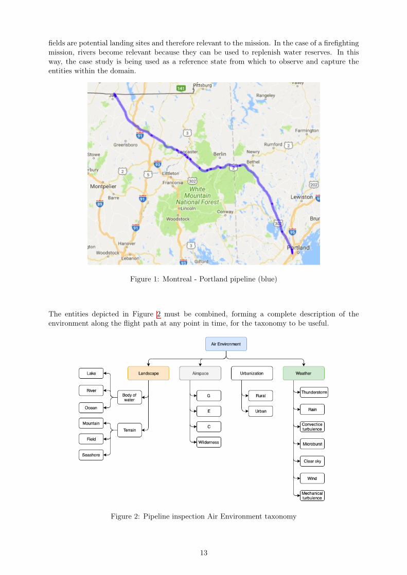
fields are potential landing sites and therefore relevant to the mission. In the case of a firefightingmission, rivers become relevant because they can be used to replenish water reserves. In thisway, the case study is being used as a reference state from which to observe and capture theentities within the domain.
Figure 1: Montreal - Portland pipeline (blue)
The entities depicted in Figure 2 must be combined, forming a complete description of theenvironment along the flight path at any point in time, for the taxonomy to be useful.
Figure 2: Pipeline inspection Air Environment taxonomy
13

Figure 3 is an example of the use of the taxonomy to describe environments that may be encoun-tered by the inspection aircraft as it moves along its flight path. The three Venn diagrams in thefigure are used to represent different flight environments, where each diagram is associated witha type of airspace. In the case of this example, class G, C and wilderness areas are representedseparately, and for each airspace, a set of potential environmental conditions are depicted in thediagram. Each diagram has four possible combinations of environmental entities, each denotedby a letter. Using all possible combinations of the environmental entities listed in Figure 2,several hundred descriptions of possible air environments could be generated.
Figure 3: Flight situation Venn diagram examples
The problem with this approach is the difficulty in visualizing the relationships between entitiesas the number of categories and sub-categories increases. The other difficulty with the taxonomicapproach is communicating the relationship between the various entities of the air environmentand the air vehicle itself, such as the fact that a helicopter may land in a field while an aircraftrequires a runway. In order for the taxonomy to be employed in a useful manner, this relationshipmust somehow be embedded in the taxonomy itself. For example, the pipeline route shown in aGoogle Maps setting in Figure 1 is useful for visualizing the route with respect to geographicalfeatures such as mountains, rivers and coastline; and urban features such as highways and largeurban centers.
In the case where the operator of the aircraft requires more detailed topographic information,
14

visual checkpoints, and information about infrastructure such as navigational aids, airports andairspace boundaries, the map shown in Figure 4 is more representative of the data that needsto be accessed. Produced by the FAA, sectional aeronautical charts are one of the primarynavigational reference media used by the aerospace community. They contain topographic andcheckpoint information including populated areas, drainage patterns, roads, railroads, and otherdistinctive landmarks. Aeronautical information on the charts includes visual and radio aids tonavigation, airports, controlled airspace, restricted areas, obstructions and related data. Themap indicates the geographic limitations of airspace, as well as special use airspaces (SUA) suchas military operations areas (MOA). Sectional charts are prepared by the FAA, primarily for useby slow to medium-speed aircraft operating under Visual Flight Rules (VFR) at lower altitudes,and are updated every 6 months. The information shown in Figure 4 is an example of a groupof air environment entities that would need to be accessed and their relationship defined for thesame Montreal-Portland pipeline inspection mission depicted in Figure 1.
Figure 4: Montreal - Portland pipeline (sectional chart)
While the sectional chart in Figure 4 provides information for the VFR pilot who relies primarilyon visual cues, aircraft operating under Instrument Flight Rules (IFR) rely on a different set ofdata, rather than visual references, for navigation. The En-route Aeronautical Navigation chartsare provided by airworthiness authorities such as the FAA in the United States and provide nav-igational information in the form of data that may be entered into computer-based navigationalsystems for the purpose of planning and executing flight routes. En-route charts are available inboth low and high altitude versions and contain information on radio navigation aids (navaids)such as VORs and NDBs, navigational fixes (waypoints and intersections), standard airways,airport locations and minimum altitudes. Information not directly relevant to instrument navi-gation, such as visual landmarks and terrain features, is not included. Figure 5 shows the same
15

pipeline inspection route shown in Figure 1 and Figure 4 plotted in the context of a low-altitudeen-route chart. The black lines in Figure 5 denoted “Vxxx” are designated Victor routes used fornavigation. The routes are analogous to a highway system in the sky. The high-altitude versionof the map is used to plot jet routes.
Figure 5: Montreal - Portland pipeline (low altitude en-route chart)
While the taxonomy from Figure 2 could be expanded to include navigational facilities, airfields,ATC and air traffic as shown in Table 1, the result is cumbersome for the stated purpose ofcommunicating a common understanding of the air environment. All three maps show thepipeline inspection route and in a global sense, could be used as a basis for a single taxonomy. Infact, the different maps lend themselves to very specific uses. For example, the map in Figure 1would be useful to provide information on the routing and length of the pipeline, and its locationwith respect to major roadways and urban infrastructure for an individual that wished to bidon a contract for the pipeline inspection and was interested in general information regardingthe environment. However, an individual wishing to fly the pipeline inspection in an aircraftflying under VFR conditions would find the information provided in Figure 4 more useful forplanning and executing the inspection. A third individual wishing to fly a portion of the routeunder IFR conditions would not find the map in Figure 4 adequate, and would require the dataprovided in Figure 5 in order to complete the mission. While a taxonomy is adequate to presenta hierarchical ordering of entities, it is unable to express complex relationships and does notconsider the relationship between the choice of entities and the planned use that is to be madeof the information such as flight operations.
The example provided above demonstrates that, while a taxonomy can be used as a generalcategorization, the taxonomical approach is limited by the hierarchical relationship between cat-
16
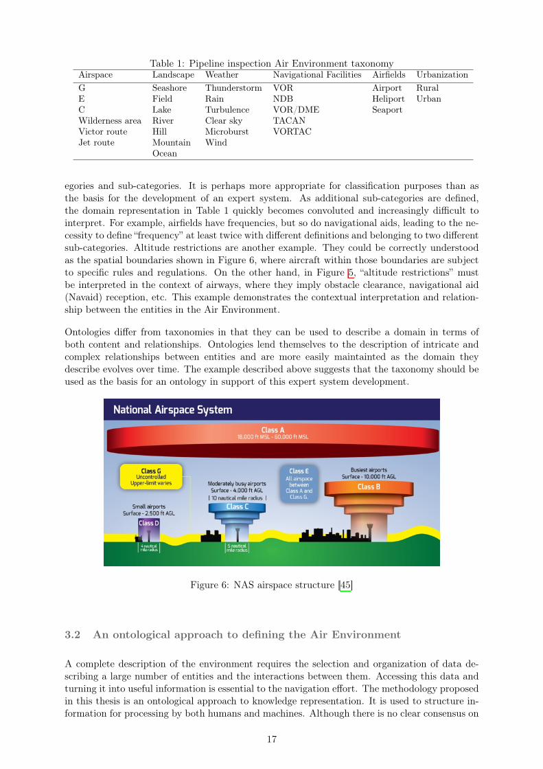
Table 1: Pipeline inspection Air Environment taxonomyAirspace Landscape Weather Navigational Facilities Airfields UrbanizationG Seashore Thunderstorm VOR Airport RuralE Field Rain NDB Heliport UrbanC Lake Turbulence VOR/DME SeaportWilderness area River Clear sky TACANVictor route Hill Microburst VORTACJet route Mountain Wind
Ocean
egories and sub-categories. It is perhaps more appropriate for classification purposes than asthe basis for the development of an expert system. As additional sub-categories are defined,the domain representation in Table 1 quickly becomes convoluted and increasingly difficult tointerpret. For example, airfields have frequencies, but so do navigational aids, leading to the ne-cessity to define “frequency” at least twice with different definitions and belonging to two differentsub-categories. Altitude restrictions are another example. They could be correctly understoodas the spatial boundaries shown in Figure 6, where aircraft within those boundaries are subjectto specific rules and regulations. On the other hand, in Figure 5, “altitude restrictions” mustbe interpreted in the context of airways, where they imply obstacle clearance, navigational aid(Navaid) reception, etc. This example demonstrates the contextual interpretation and relation-ship between the entities in the Air Environment.
Ontologies differ from taxonomies in that they can be used to describe a domain in terms ofboth content and relationships. Ontologies lend themselves to the description of intricate andcomplex relationships between entities and are more easily maintainted as the domain theydescribe evolves over time. The example described above suggests that the taxonomy should beused as the basis for an ontology in support of this expert system development.
Figure 6: NAS airspace structure [45]
3.2 An ontological approach to defining the Air Environment
A complete description of the environment requires the selection and organization of data de-scribing a large number of entities and the interactions between them. Accessing this data andturning it into useful information is essential to the navigation effort. The methodology proposedin this thesis is an ontological approach to knowledge representation. It is used to structure in-formation for processing by both humans and machines. Although there is no clear consensus on
17

the definition of “ontology”, the research presented here adopts the definition from Kendall andMcGuiness [40]:
“The primary reason for developing an ontology is to make the meaning of a set of concepts,terms, and relationships explicit, so that both humans and machines can understand what thoseconcepts mean. An ontology specifies a rich description of the
1. terminology, concepts, nomenclature;
2. relationships among and between concepts and individuals; and
3. sentences distinguishing concepts, refining definitions and relationships (constraints, re-strictions, regular expressions)
relevant to a particular domain or area of interest.”
The intent is to demonstrate that, through a precise definition and organization of terms, an AirEnvironment ontology will define a comprehensive picture of the environment in which aircraftoperate. This definition can be used as a foundation for autonomous navigational decision-makingin a shared airspace. The study uses a descriptive logic approach where the ontology is specifiedin terms of concepts (classes), roles (properties or relationships) and instances (individuals).This structure provides a means of accessing and communicating the data that exists within theenvironment in a form that is useful for expert systems. The terms that are used in the studyare defined below:
1. Domain: A subset of “All Things” (ie. the super-class or highest possible level of abstrac-tion). In this case, the domain is the “Air Environment”.
2. Class: A concept in the domain. Classes can be connected to other classes through re-lationships, or object properties. Classes may also have attributes described by datasetsand are called data properties. In an ontology, classes are organized in a hierarchicalsub-class/super-class manner.
3. Property: used to further refine class definitions in an ontology. They typically describe thecharacteristics and features of the members of a class, as well as link that class to others.Properties are divided into two types; object properties (relationships between classes andindividuals that are members of those classes) and data properties. Data properties are usedfor simple attributes that typically have primitive data values (e.g., strings and numbers).
4. Individual: A specific named instance of a class.
The approach to developing the ontology is adapted from Kendall and McGuinness [40] andemploys the following steps:
1. Select a subset of a domain, identify use cases and prepare a list of terms;
2. Research existing ontologies/vocabularies to determine reusability;
3. Identify concepts and preliminary relationships between them;
4. Identify and extend concepts in existing ontologies/vocabularies that they are appropriatefor our use case;
5. Connect concepts through properties (relationships); and
18

6. Conduct a basic verification test.
Domain and use case selection
The domain of study is the Air Environment. The ontology produced enables a computer tomake navigational decisions in the context of the aircraft mission. For this reason, an additionalontology is added; the Air Vehicle (AV). The Air Vehicle ontology, when reconciled with the AirEnvironment, provide the necessary elements to make navigational decisions. The use cases aredescribed in section 5. The data properties defining specific class individuals are stored externallyin SQL databases and the relationships between all objects is by nature defined in the ontology.
Identifying existing ontologies
The concept of an Air Environment ontology has been considered by a number of organizations.Keller describes NASA’s air traffic management ontology, the development of which was driven bya need to “integrate heterogenous forms of aviation data for use in aeronautics research.” [86, 85].It contains concepts that relate to all aspects of the national airspace such as flight information,aircraft and manufacturers, infrastructure, airlines, and NAS facilities. The ontology producedin this thesis builds on Keller’s work and maintains a consistent terminology by retaining thoseconcepts relevant to in-flight navigation and removing those that are not.
The European Organization for Safety of Air Navigation (EUROCONTROL), the FAA and IATAhave also collaborated to generate industry-wide standards for data interoperability. The goalis to address the increasingly large amounts of data that are becoming available by facilitatingcommunication between data suppliers (for example the FAA or NOAA) and consumers such aspilots and aviation data providers. The collaboration has yielded three different models which canbe downloaded for free as XML files: Aeronautical Information Exchange Model (AIXM), FlightInformation Exchange Model (FIXM) and Weather Information Exchange Model (WXXM).The AIXM provides data including airspace routes and boundaries, procedures, navaids andairports [41]; FIXM data is related to individual flights [42]; and WXXM provides meteorologicalinformation [43]. All three models are highly granular and complex. For the purpose of this thesis,concepts are taken from the AIXM and WXXM, but the terminology is adapted.
Identifying concepts and preliminary relationships
The Air Environment domain maps the concepts describing the environment in which the AirVehicle operates for the purpose of in-flight navigation. Preliminary classes selected to describethe Air Environment domain include weather, navigational facilities, airfields, airspace, air traf-fic, terrain, and Air Traffic Control (ATC). The following sections provide a non-exhaustivedescription of these concepts and class descriptions. The full ontology, complete with all classes,is linked at the end of Section 4.2.
3.2.1 Weather
A survey of all FAA weather Advisory Circulars (AC) was performed to source weather propertiesfor the ontology. AC00-6 [12] provides information on weather phenomena and their mechanisms;AC00-45 [13] on where and when what information can be found; and AC00-30 [17], AC00-54 [25]and AC00-57 [21] provide heuristics on how to detect the possibility of and manage encounterswith clear air turbulence, wind shear and hazardous mountain winds, respectively. Based on thesedocuments, the weather class is divided into four sub-classes: icing, precipitation, convection andwind. This subclass selection is meant to represent a high level of abstraction from which manyother weather phenomena can be defined. Tables 2 through 5 show the sub-classes, properties,and data sources used to define individuals stored in external databases.
19

Table 2: Wind Sub-classesSub-class (‘is-a’ relationship) Properties (‘has-a’ relationship) Individual Data SourcesLow level wind shear (LLWS) has-altitude, -latitude, -longitude AIRMET T, SIGMET, SIG WXSurface wind has-altitude, -latitude, -longitude AIRMET TMountain wave turbulence has-altitude, -latitude, -longitude AIRMET T, GTGClear air turbulence has-altitude, -latitude, -longitude AIRMET T, GTGTemperature has-altitude, -latitude, -longitude FD, METAR/SPECI, TAFWind speed has-altitude, -latitude, -longitude FD, radar VWP, METAR/SPECI, TAFWind direction has-altitude, -latitude, -longitude FD, radar VWP, METAR/SPECI, TAF
Table 3: Convection Sub-classesSub-class (‘is-a’ relationship) Properties (‘has-a’ relationship) Individual Data SourcesConvection line has-altitude, -latitude, -longitude, -probability CCFPConvection area has-altitude, -latitude, -longitude, -probability CCFPCumulonimbus has-altitude, -latitude, -longitude SIG WX (mid/high-level)Cloud top has-altitude, -latitude, -longitude SIG WX (mid/high-level), SIGMETCell movement has-altitude, -latitude, -longitude SIGMETThunderstorm has-altitude, -latitude, -longitude SIGMET, PIREP
Table 4: Icing Sub-classesSub-class (‘is-a’ relationship) Properties (‘has-a’ relationship) Individual Data SourcesFreezing level has-altitude, -latitude, -longitude FD, SIG WX (low-level), SIGMET, AIRMET ZSeverity has-altitude, -latitude, -longitude AIRMET Z, PIREP, SIG WX (mid/high-level), CIP/FIPProbability has-altitude, -latitude, -longitude CIP/FIPSLD potential has-altitude, -latitude, -longitude CIP/FIPFreezing drizzle has-latitude, -longitude METAR/SPECI, TAFFreezing rain has-latitude, -longitude METAR/SPECI, TAFSleet has-latitude, -longitude METAR/SPECI, TAF
Table 5: Precipitation Sub-classesSub-class (‘is-a’ relationship) Properties (‘has-a’ relationship) Individual Data SourcesRain has-altitude, -latitude, -longitude, -intensity Radar, PIREP, METAR/SPECI, TAFSnow has-altitude, -latitude, -longitude, -intensity Radar, PIREP, METAR/SPECI, TAF
3.2.2 Navigational Facilities, Airfields and Airspace
Concepts related to infrastructure are grouped together. Properties pertaining to those con-cepts are sourced from documents available to pilots, namely sectional maps, IFR low and highen route maps, the airport/facility directory (A/FD) and the terminal procedures publication(TPP). Table 6 provides examples of sub-classes, properties and data sources for the AirportInfrastructure Component class.
Table 6: Airport Infrastructure Component Sub-classesSub-class (‘is-a’ relationship) Properties (‘has-a’ relationship) Individual Data SourcesAirspace has-Airspace-Area Sectional chartApproach has-Approach-Procedure TPPRunway has-Runway ID AF/DStandard Terminal Arrival Route has-STAR-Procedure TPPStandard Instrument Departure has-SID-Procedure TPP
20

3.2.3 Air Traffic and Air Traffic Control
Traffic properties are taken from what can be obtained from an ADS-B Out message. Given theFAA’s recent requirements for ADS-B equipment and that the rest of the world is also adoptingADS-B, it is assumed that aircraft will be properly equipped and hence, that the following datais available [44].
Table 7: Air Traffic ClassProperties (‘has-a’ relationship) Individual Data Sourceshas-Heading ADS-B Outhas-Callsign ADS-B Outhas-Time since last report ADS-B Outhas-Speed ADS-B Outhas-Altitude ADS-B Outhas-Vertical speed ADS-B Outhas-Longitude ADS-B Outhas-Latitude ADS-B Outhas-On ground status ADS-B Outhas-Squawk ADS-B Out
3.2.4 Terrain
Terrain details are obtained from results of the NASA Shuttle Radar Topography Mission(SRTM), which freely provides topographical data of 30m resolution [28]. Terrain is describedas sets of discrete points for which there are elevation, latitude and longitude figures.
3.3 The Air Vehicle
The Air Vehicle (AV) is the ontological domain used to describe a generic form of aerial vehi-cle. In the current study the Air Vehicle ontology is populated with the minimum amount ofinformation necessary for a specific navigational use case in the Air Environment. Two types ofclasses are specified; systems and system state.
The AV is understood as a “collection of systems”, where a “system” is a physical construct thatprovides a function or collection of functions. The system functionality relates directly to systemhealth or state. Specific examples of generic air vehicle systems and their functions are listedbelow:
1. The anti-ice system is a collection including pipes, reservoirs (TKS) and pumps that enablesthe AV to remove ice from the airframe.
2. The flight control system (FCS) is a collection including moveable surfaces and actuatorsthat enables the AV to maintain control.
3. In the case of hydraulically actuated controls, the hydraulic system is a collection includingpipes, pumps, and reservoirs, and is related to the FCS.
Each system has properties to describe its functionality, as well as a group of classes to de-fine that functionality. For example, the Class ‘TKS anti-ice system’ can have subclassesincluding ‘OperationalState’, ‘FluidQuantity’, and ‘FluidFlowRate’; and Properties including‘has-OperationalState”, ‘has-a-FluidQuantity’, and ‘has-a-FluidFlowRate”. These anti-ice sys-tem classes, individuals and properties can be used to define the anti-ice system performance
21

of the Air Vehicle in terms of available flight time in icing conditions. Similarly, if an AV isequipped with high lift devices (HLD), the “landing distance” performance parameter dependson the functionality of the HLD.
The anti-ice system description demonstrates how “system” and “functionality” combine to define“performance”, or the ability of the AV to interact with the air environment. Figure 7 providesexamples of how system functionality and performance are linked.
Figure 7: Examples of systems, functionality and state
3.4 Establishing Context
Context frames the goals by gathering all ontological concepts; the AV performance, functionality,and the environment. The first step in establishing context is to determine what is achievableby the AV, which considers both the functionality of the systems and the air environment. Thisconsideration results in a flight mode which reflects the intent of the AV. For example, if the AVis flying in icing conditions and the anti-icing system fails, the intent of the AV is to exit theicing conditions. Flight mode, performance and environment are then combined to determinewhich actions reflective of the intent should be carried out to navigate the environment. Thisflow is shown in Figure 8. In the icing scenario, the AV may opt to increase airspeed andclimb to exit the hazardous flight situation, or it may choose to do nothing if it is alreadydescending towards its destination. To make these decisions, the AV must consider its availableperformance. Ontologically, flight modes are described by short expressions such as “avoid ice”,“degraded cruise”, or “diversion”.
Figure 8: Context
Figure 9 shows an example of a possible icing context and gives examples of the kinds of environ-mental and performance elements the AV must consider when making a decision. In the contextof avoiding ice, there are three possible actions; climb, descend or otherwise alter the trajectory.
22

Figure 9: Icing context
3.5 Decision-making
The decision-making process is iterative and considers the environment, the AV, and the flightmode. It aims to determine if the current context is maintainable, or if it must change. Thedecision-making cycle also recognizes that the state of the environment is a variable that cannotbe changed by the AV, it is non-negotiable. The process is shown in Figure 10 and built of threemain questions:
1. Given the state of the environment and the flight mode, are the AV systems capable?
2. Given the state of the environment and the state of the AV systems, can the AV systemsbe reconfigured to maintain the current flight mode?
3. Given the capabilities of the AV systems and the flight mode, how can the environment benavigated?
The following Sections 3.5.1 and 3.5.2 provide examples of how the decision-making processunfolds for two specific scenarios. Section 3.5.1 describes the process for the case of an icingevent, and Section 3.5.2 for the case of an in-flight engine failure.
23

Figure 10: Decision making question cycle
3.5.1 Scenario 1: Icing Encounter
The air vehicle is configured as a twin-engine, piston-powered Part 23 aircraft certified for flightinto known icing conditions, equipped with a TKS ice protection system.
Initial conditions:
1. The aircraft is cruising at altitude when icing conditions on the planned flight path aredetected.
2. The flight mode is “cruise normal”.
3. All aircraft systems are performing normally and the anti-ice system is off.
Iterative decision-making process:
1. Q: Given the state of the environment and the flight mode, are the AV systems capable?A:No, because icing conditions have been detected and the anti-ice system is off.
2. Q: Given the state of the environment and the state of the AV systems, can the AV systemsbe reconfigured to maintain the current flight mode?A: Yes, and the required reconfiguration is to turn on ice protection.
3. Q: Given the capabilities of the AV systems and the flight mode, how can the environmentbe navigated?A: Evaluate how long the TKS system can operate to determine range on TKS. If insuffi-cient fluid is on-board to traverse region of icing, then find a new altitude, alter the route,fly faster, etc. . .
4. Return to step 1.
24

Figure 11: Icing encounter question flow
3.5.2 Scenario 2: Engine Failure
The air vehicle is again configured as a twin-engine, piston-powered Part 23 aircraft certified forflight into known icing conditions, equipped with a TKS ice protection system.
Initial conditions:
1. The aircraft is cruising at altitude when an engine failure is detected.
2. The flight mode is “cruise normal”.
Iterative decision-making process:
1. Q: Given the state of the environment and the flight mode, are the AV systems capable?A: No, because an engine has failed
2. Q: Given the state of the environment and the state of the AV systems, can the AV systemsbe reconfigured to maintain the current flight mode?A: No, because the engine cannot be restarted. Decide to change the flight mode to“degraded cruise” and “divert”.
3. Q: Given the capabilities of the AV systems and the flight mode, how can the environmentbe navigated?A: Find the nearest suitable field and fly to it.
4. Return to step 1.
25

Figure 12: Engine failure question flow
�
26

4 Implementation
4.1 Ontology
The ontology was implemented in Protégé (Stanford University, USA), a free open-source plat-form for opening, building and visualizing ontologies. Its ability to open a wide array of formats,and user-friendly interface lends itself well to quick development. Protégé can also be used toopen existing ontologies such as AIXM and NASA ATM to better understand how they areconstructed. A final ontology was built for the purpose of navigation in the air environment.
The ontology in Figure 13 contains the following classes; Environment, FlyingBlob (the AV),TimeSlice, and Value. TimeSlice introduces the concept of time, necessary because the state ofthe air environment depends on time. Weather is highly dynamic since conditions are constantlychanging, and even though the airspace infrastructure changes slowly, it does change over time.For example, airports may extend runways or navigational aids may be taken out of service.Value is added as a mechanism to create sequential or non-sequential groups of elements. Forexample, airport weather reports can at times report sequences of cloud layers. Value is used togroup them together into a single sequential element. This helps keep the ontology organized.
Figure 13: Ontology high-level concepts
4.1.1 The Environment
The environment is divided into terrain, National Airspace System (NAS), weather, air trafficand regulations as shown in Figure 14. A Regulations concept is included because the airenvironment is a regulated domain and depending on the context, aircraft decisions depend onwhat is permitted by operational regulations. The NAS concept groups sub-classes includingairports and airspace.
Figure 14: Environment concepts
27

4.1.2 The Air Vehicle (aka FlyingBlob)
The air vehicle is defined by several sub-classes depicted in Figure 15. Performance and Sys-temHealth are related in that performance depends on the state of the systems. For example,an aircraft which has a failed engine will not climb as well as if it had all engines operating.Route represents the air vehicle’s flight plan. Air routes, airports, waypoints and other suchinformation are contained in the Route class. Blobaroo is an instance of the FlyingBlob class,and defines concrete values for performance, route, mode and system health that are specific toBlobaroo.
Figure 15: Air Vehicle concepts
4.2 The Route Class
This section describes the route class to explain how the ontology is implemented in Protégé,which uses properties to define relationships between classes. Data properties are used to specifyallowable class property values. This mechanism builds the ontological web.
Further expanding Route reveals the following object properties, shown in Figure 16 by dashedarrows. The object properties connect other classes to the Route class. Object property rela-tionships are denoted by <>.
1. <hasPlannedArrivalRunway>
2. <hasPlannedSID>
3. <hasPlannedSTAR>
4. <hasPlannedApproach>
5. <hasPlannedArrivalAirport>
6. <hasPlannedDepartureAirport>
7. <hasPlannedDiversionAirport>
8. <hasPlannedRoute>
9. <hasPlannedDepartureRunway>
28

Figure 16: Route object properties
Inspecting the _runway object reveals the following:
Figure 17: Runway object
1. _runway is a subclass of Airport Infrastructure Component
2. Airport Infrastructure Component <hasRunway >_runway
3. Route <hasPlannedDepartureAirport>, <hasPlannedArrivalAirport>and <hasPlanned-DiversionAirport>which are of class Airport Infrastructure Component
4. Flight modes _takeoff and _landing <hasActiveRunway>_runway
5. _runway has 4 defined instances (purple diamonds); runway15-33, runway18-36, runway5-23 and runway1-19
6. Airport Infrastructure Component has an instance KBTV which <hasRunway>runway15-33
7. Route <hasPlannedArrivalRunway>and <hasPlannedDepartureRunway>which are of class_runway
Class instances are referred to as individuals (or objects). Each runwayXX-XX individual isa concrete definition of a runway in the domain. For example, runway15-33 is defined bythe following data properties: dp_RunwayWidth, dp_RunwayLength, dp_RunwayDirection,dp_RunwaySurface. All data properties are prefixed by “dp_”.
29

Figure 18: runway15-33 object data properties
The complete ontology can be viewed here:http://www.visualdataweb.de/webvowl/#iri=https://sigur.ovaltofu.org/paul.public/website/environment.owl
4.3 Databases
Before implementing the concepts previously listed (weather, navigational facilities, airfield,airspace, air traffic, terrain, ATC, Air Vehicle), internet searches were performed to determinewhat data are openly available. Results of those searches indicate that the United States pro-vides many data. The implementation is however not limited to the United States, as long asdata from other countries is available. Data describing the United States is taken for the studybecause it is plentiful and easily accessed.
The following tables list the associated data sources. This list is not exhaustive, and pools linksfrom the National Oceanic and Atmospheric Administration website, since it is open access andeasily accessible.
Table 8: Weather Data Sources & FormatsIcing Wind Precipitation Convection
CIP/FIP GRIB 1 [73]Airmet Z BUFR [74], XML [81]Sigmet BUFR [75], XML [81] BUFR [75], XML [81] BUFR [75], XML [81]PIREP XML [81] XML [81] XML [81]Sig Wx BUFR [75], XML [81] BUFR [75], XML [81] BUFR [75], XML [81]TAF XML [81] XML [81] XML [81] XML [81]METAR TXT [76], XML [81] TXT [76], XML [81] TXT [76], XML [81] TXT [76], XML [81]GTG GRIB 1/2 [73]Airmet T BUFR [77], XML [81]Radar BIN [78] BIN [79]CCFP TXT [80]
Table 9: Weather Data Sources & FormatsNavigational Facilities Airports Airspace
Airports JSON [10]Runways JSON [26]Routes JSON [11]CIFP ARINC 424-18 [18] ARINC 424-18 [18] ARINC 424-18 [18]
The CIFP is entered as a row of its own because it contains many data. Listing them individuallywould be too exhaustive.
30

Air Traffic data is obtained from the ADS-B Exchange website [44], which provides a pythonAPI. The API returns traffic data in JSON format.
SRTM terrain data is downloaded as a binary data file. Each file carries discrete points for a1 degree of latitude by 1 degree of longitude tile. Each file contains a series of 16-bit integersgiving the altitude of each cell. Each tile is separated into a grid of 3601 by 3601 cells for atotal of 12967201 cells. Each 16-bit integer can then be associated to the correct latitude andlongitude, since the coordinates of the first cell is known.
Since the data come in seven different formats, Structured Query Language (SQL) databases arecoded. This not only unifies all data into one format but is also useful to efficiently search fordata.
Data is coded into four distinct databases: CIFPRev12.sqlite, environmentRev8.sqlite, Icin-gRev3.sqlite and srtm3.sqlite. Each database contains tables that each contain data describingthe air environment. Table 10 lists what SQL tables are contained in each SQL database.
Table 10: SQL DatabasesCIFPRev12.sqlite environmentRev8.sqlite IcingRev3.sqlite srtm3.sqliteAirspaces airfields IcingInfo1 N44W073AirwayRoutes airports IcingInfo2 N44W073_LR_1in10Approaches runways IcingInfo3 N44W073_LR_1in3Runways . . . N44W073_LR_1in50SIDs . . . N44W074STARs . . . N44W074_LR_1in10Waypoints IcingInfo30 N44W074_LR_1in3
N44W074_LR_1in50
Notes:
1. Airfields and airports are different from each other because the “airfields” table does notcontain any runway information. “airports” table combines “airfields” and “runways”
2. IcingInfoXX contains icing information for 1000 feet increment. For example, icing infor-mation at 3000 feet is contained in table “IcingInfo3”
3. NxxWxxx contains topographical information for a tile of 1 degree latitude and longitude.LR abbreviates “low resolution”, and 1inX means the table in question contains 1 in Xpoints from the original table. For example, N44W073_LR_1in50 contains 50 times lesspoints than N44W073. Certain flight modes may require a certain resolution. For example,an aircraft on approach needs access to high resolution terrain data, while one cruising at30000 feet may not need any at all.
4.4 Programming Implementation
Python is the programming language used to integrate the different program components. It isused as the interface to join CLIPS, SQL and OpenGL. The CLIPS python binding CLIPSPybrings CLIPS 6.30 capabilities into the program and is used as the expert system shell. OpenGLruns a graphical interface to display the data in real time, and SQL stores and provides aninterface to quickly query the data.
Since most of the data queries are geographical queries, a means to quickly search 3D space isneeded. Operations to determine icing severity around the AV within a certain radius at a certainaltitude, the locations of nearest airports, or if the AV is in a given type of airspace are examples
31

of computations that need to be efficiently calculated during short time intervals. SpatiaLite [5]is an open-source library intended to extend the SQLite core to support spatial SQL capabilities,and is seamlessly integrated into SQLite. SpatiaLites’ spatial computational abilities dependon geometries, which exist as BLOBs (Binary Large OBject) in SpatiaLite terminology. Forthat reason, several SQL tables in the databases described above have BLOB columns. Thedata contained in those columns are repackaged human readable data (latitude, longitude andaltitude) into the binary format required by SpatiaLite.
4.4.1 The Python Route Class
Pythons object-oriented programming paradigm lends itself well to recreating the Protégé ontol-ogy.
To compare the Protégé ontology with the python class structure, this section looks at howthe Route class is implemented in python code. The Route class is defined by properties andinstance methods. The properties are the python analogues to the Protégé <has_>possessives.The instance methods provide a mechanism to build the individuals and their possessive linksat runtime.
Figure 19: Python route class
The Python Route class contains many of the Protégé possessives. The following differences arenoted and explained:
1. Missing <hasPlannedDiversionAirport>. Though the object structure does not explicitlyinclude one, the python implementation includes a function that searches for the nearestusable diversion field when one is required. The criteria for a field to qualify as usable arecontext dependent, and rely on required landing distance, fuel range, wind, etc. Since theprogram only uses a diversion airport when it is required, it is not included in the objectstructure. This is a design choice, and it would have also been acceptable to provide it aplaceholder in the Route object structure.
2. Missing <hasPlannedSID>. Standard Instrument Departures are left out because the SIDdata in the CIFPRev12.sqlite database have not been formatted into SpatiaLite BLOBs.
32

3. Missing <hasPlannedDepartureRunway>and <hasPlannedArrivalRunway>. It is redun-dant to include runways in the Route object since the STAR and Approach objects specifythe selected arrival runway as a property. Therefore, Table 11 marks <hasPlannedArrival-Runway>as included, even though it is not shown in Figure 19.
4. <hasPlannedRoute>_plannedRouting is implemented by AirwayLeg and WptLeg classes.Both objects build route legs along airways or a succession of waypoints, respectively.
Table 11: Route Object: Protege vs. PythonProtégé Python<hasPlannedArrivalRunway> �<hasPlannedSID> �<hasPlannedSTAR> �<hasPlannedApproach> �<hasPlannedArrivalAirport> �<hasPlannedDepartureAirport> �<hasPlannedDiversionAirport> �<hasPlannedRoute> �<hasPlannedDepartureRunway> �
Each class has methods to build the object properties during initialization, and to modify themat runtime. For example Route has a method called “buildAirwayLeg”. By calling “buildAirway-Leg([“MPV”, “V447”, “PLOTT”])”, the function searches the CIFP database for all points alongvictor route 447 starting at MPV and ending at PLOTT. All other objects in the python codefollow a similar methodology.
4.4.2 CLIPSPy – A Python CLIPS Binding
CLIPSPy is central to the decision-making process. It depends on an internal representationof the environment, the knowledge base, which is distinct from the Python object structure.The knowledge base is made up of facts and rules which define what CLIPS knows as “true”about the world, and what to “do” given a state of truth. Since environmental parameterssuch as Routing and weather are stored in Python objects, python listeners are used to detectchanges in environment state, so that the CLIPS internal representation (facts) can be updatedaccordingly. This ensures that the CLIPS knowledge base identically mirrors the Python objectindividuals. For example, if the next active waypoint in the Route object updates because theAV has sequenced to the next point in the flight plan, listeners update the CLIPS knowledge baseto reflect the change. Additionally, because navigational decisions are made by CLIPS but areexecuted by python, listeners are also used to determine what navigational action plans need tobe performed by python given a CLIPS truth state. The CLIPSPy binding makes this seamless.Finally, all AV system configurations are managed internally by CLIPS. Figure 20 visualizes thismethod.
Figure 20 shows that:
1. The CLIPS knowledge base Weather knowledge listens for changes in weather data
2. The CLIPS knowledge base Flight plan knowledge listens for changes in active waypointfrom the python flight plan object (the route object).
3. Python listens to the CLIPS knowledge base Flight Mode to determine which navigationalaction plan should be executed.
33

4. Changes in data and flight plan are rendered in an OpenGL window. This window existsto accomodate the human user, who may be monitoring the system. The program doeshowever work indepentently of the display, and it is not required.
Figure 20: CLIPS Python integration
Various combinations may lead to changes in flight mode, for which python listens to. If a flightmode has a corresponding navigational action plan, then python executes it. The second methodfor python to execute a navigational action plan is through air traffic control commands, whichare implemented in python by means of hotkeys.
Figure 20 also shows that in the CLIPS knowledge base, Weather and AV performance impactFlight Mode, but that the relation does not go in the other direction (ie these are ‘non-negotiable’elements of the world). Flight plan and AV system configuration have a bi-directional relationshipwith Flight Mode. This is also described in 3.5 Decision-making.
The knowledge base is composed of the following facts and rules:
• Facts:
– BlobPerf: AV performance information– BlobSystem: AV system status information– FlightMode: current flight mode– NavWaypoints: next active flight plan waypoint information– NavApproach: airport approach information– EnrouteWx: enroute weather information
• Rules:
– Engine_failure_diversion: diversion action– Anti_ice_system_on: manage anti-ice system– Anti_ice_system_off: manage anti-ice system
34

– Anti_ice_fail_climb: anti-ice failure– Anti_ice_fail_cruise: anti-ice failure– Approach_fight_mode: switch to approach flight mode– Landing_gear_down: when to lower the landing gear
If the decision-making process impacts the routing or the altitude, the OpenGL render reflectsthose changes. The terminal window displays the CLIPS knowledge base. Each time the knowl-edge base is updated, the terminal window reprints the entire knowledge base, as well as whatchange was detected, and what decision if any, was made.
�
35

5 Results
This section presents results of two simulated scenarios and introduces a validation exerciseperformed on-board an aircraft. All scenarios take place on a flight between Burlington airport(KBTV) and Newport State airport (KEFK). For the simulated scenarios, a twin-engine aircraftwith anti-ice capability is assumed, represented in the program render by a red dot and followsa simulated trajectory.
The waypoints on the flight plan are in order and plotted on a sectional in Figure 21:
1. PLOTT
2. LUNFI
3. YISXI
4. AHTON
5. ROMUW
6. KEFK (Northeast Kingdom): this is the destination airport
Figure 21: KBTV to KEFK routing (purple)
5.1 Scenario 1: Anti-ice activation/de-activation and approach mode
In this scenario, the anti-ice activation rules are tested, as well as the transition to “approach”flight mode. As changes in ice severity are detected, the status of the anti-ice system is adjustedinternally by CLIPS. The following sequence of figures demonstrates how the program works.
36

5.1.1 Departing Burlington (KBTV)
After departing Burlington, the AV initiates a climb to 7000 feet. Initially, the AV is not in aregion of ice. The terminal displays the CLIPS knowledge base. Each fact holds a representationof what is true, and CLIPS bases its decisions on those facts. Each fact discussed in 4.4.2CLIPSPy is displayed below:
This information indicates that all systems are running normally, the AV is climbing through2000 feet and is headed to the PLOTT waypoint. The OpenGL render is shown in Figure 22,with the AV represented as a red dot.
Figure 22: OpenGL render - Climb to 7000 ft departing Burlington
5.1.2 Encountering Icing Conditions
Upon reaching 3000 feet, the system encounters icing of severity 4, rendered as purple squares.The icing scale ranges from 0 to 5, 5 being the most severe. At this point, the flow of Scenario1 in the methods section is executed. In Python, the flow is as follows:
1. Weather data is obtained from the SQL icing database and updated in the Python object
37

structure
2. Highest icing severity in the area is updated to the CLIPS knowledge base by listeners
3. The icing severity triggers a response from the CLIPS knowledge base: at icing severity 4,anti-ice systems must be turned on.
4. CLIPS turns on the anti-ice system. Since the system has not failed, no change to theflight plan is required and the AV continues on to PLOTT.
Figure 23: OpenGL render - Icing encounter
After passing PLOTT, the AV turns north to LUNFI, which is part of the GPS 36 approachinto Newport. The system switches to “approach” flight mode, which in turns lowers the landinggear. CLIPS displays any change in the environment by declaring “Event:” and announces anydecisions by declaring “Decision:”. CLIPS then re-prints the updated truth state to the terminalwindow. The terminal displays the following:
This information indicates:
38

• the Blob is in flight mode “Approach”
• the anti-ice system is “on”
• the landing gear is “down”
• the Blob is flying to waypoint “LUNFI” which is an approach waypoint.
Figure 24: OpenGL render - Sequencing to waypoint LUNFI after passing waypoint PLOTT
5.1.3 Arrival Into Newport (KEFK)
As the AV continues its descent into Newport, it eventually descends below the icing layer, andsubsequently turns off the anti-ice system. This change in icing severity is also reflected in theOpenGL render, with the absence of purple “icing squares”. The terminal outputs the following:
39

Figure 25: OpenGL render - AV descending below the icing layer passing YISXI
5.2 Scenario 2: Engine failure
The AV is on the same flight presented in scenario 1, but experiences an engine failure on its wayto PLOTT. At this point, the flow of Scenario 2 in the methods section is executed. In Python,the flow is as follows:
1. Engine failure is updated in the CLIPS knowledge base
2. This triggers a response by CLIPS to change the flight mode to “Degraded Cruise”, and to“Diversion True”
3. This change in flight mode is listened to by Python, which then executes the appropriatenavigational action plan; a diversion.
4. The action plan searches for the nearest usable airfield based on required landing distanceand obtains real time weather at the airport from the NOAA website. It then modifies theflight plan to direct the AV towards the new destination, in this case Morrisville (KMVL).At the time the simulation was run, KMVL was reporting light winds out of the north andlight snow.
40

Figure 26: OpenGL render - AV diverting to KMVL after an engine failure
5.3 Validation Exercise
The validation exercise is carried out in a Cessna Cardinal CE-177-B. Even though the Cardinalis not a twin engine piston aircraft with anti-ice capability, it serves as a proxy for the exercise.The objective is to demonstrate that:
1. The data used in the program corresponds to data used by the Garmin 430W, a widely usedcertified GPS navigation system. Examples of data contained by the Garmin 430W aredata describing the airport infrastructure component, terrain, and airspace among others.
2. The program is designed in such a way that it is suitable for making decisions in real timebased on GPS location and the data contained in the SQL databases previously discussed.
Both scenarios discussed in this section compare the program output to the Garmin 430W output.The included videos show how the tests were carried out, as well as their results.
41

5.3.1 Position Determination
Since the program is to be tested in the real environment in an actual aircraft, the simulatedtrajectory position used in the simulated tests discussed in sections 5.1 and 5.2 needs to besubstituted for actual GPS position. To obtain actual position (latitude, longitude, altitude),the Vk-162 USB GPS chip is used. The chip transmits information as per a standard defined bythe National Marine Electronics Association (NMEA) in the form of sentences [47].
The two time-stamped sentences used in the program are labelled “GNGGA” and “GNRMC”.“GNGGA” carries latitude, longitude and altitude while “GNRMC” carries speed and course.As the GPS measures these parameters, the python program reads the sentences and updatesthe latitude, longitude and altitude values in the program, effectively replacing the simulatedtrajectory by actual GPS position. That way, position, speed and heading are updated everysecond and changes are reflected in the OpenGL render. This program configuration is referredto as “real flight mode”.
Figure 27 shows the aircraft flown during the tests, and figure 28 the specific GPS chip used.Figure 29 is the in-flight setup. The left seat is occupied by the safety pilot and the right seatby the pilot in command. The image also depicts the laptop running the program, the Garmin430W and the Vk-162 GPS chip, which is not visible since it is placed on the dashboard to havesatellite visibility.
Figure 27: Cessna Cardinal CE-177-B flown in the validation flights
42

Figure 28: VK-162 GPS chip
Figure 29: Setup used in flight
Two scenarios are presented; an engine failure and a normal flight from Burlington to Newport.The ADS-B track for the flight from Burlington to Newport is obtained from flightaware.comand is shown in Figure 33. Waypoints PLOTT and LUNFI are added to the map to help situatethe reader.
43

5.3.2 Engine Failure Scenario
In the following in-flight scenario, the aircraft is positioned southwest of waypoint PLOTT,northwest bound. Prior to the simulated engine failure, the terminal displays the following:
Figure 30: Engine failure scenario initial position
At an arbitrary point in time, an engine is failed in the python program. The terminal nowdisplays the diversion airport, and updates the air vehicle system state:
44

The render now shows the calculated diversion trajectory and updated flight plan to Morrisvilleairport (KMVL):
Figure 31: Blob diverting to KMVL
The following two videos show the scenario carried out in the Cardinal. The first video is shotwith a GoPro by the safety pilot. The video shows the programs results and compares themto the Garmin 430W results by navigating to the “Nearest Airport” page, which also displaysKMVL, with a runway 3700ft long. The second video is a screen recording of the laptop as theprogram ran during the test.
1. Video 1 - Aircraft video: https://www.youtube.com/watch?v=NQLfZFU_UzM
2. Video 2 - Screen recording: https://www.youtube.com/watch?v=aYq4LB9UMTs
45

Table 12: Video 1 - Aircraft video pilot action descriptionsTime (seconds) Action5 Simulate an engine failure in the python program running in “real flight mode”14 Show the programs nearest airport selection; KMVL airport with a 3700ft runway20 Show the programs OpenGL map, reflecting the revised flight plan31 Compare program results shown at 14s with the Garmin 430W results,
which also displays KMVL with a 3700ft runway as the nearest airfield
Table 13: Video 1 - Aircraft video pilot action descriptionsTime (seconds) Action4 Simulate an engine failure in the python program running in “real flight mode”6 Pick a diversion airport and revise the active flight plan11 Icing severity 4 detected, turn on anti-ice system
5.3.3 Burlington to Newport Flight
The objective of this flight is to demonstrate that the system is capable of sequencing waypointsand properly configuring the systems given icing and flight mode in real time, as the aircraftnavigates along its route. It is also intended to validate the data in the SQL databases.
Initially, the Cardinal is positioned at Burlington (KBTV) airport. The OpenGL render displaysthe following:
Figure 32: Cardinal positioned in Burlington ready for departure
The terminal displays the following:
46

For the remainder of the flight, the OpenGL render and terminal outputs are identical to theflight presented in 5.1 and are thus not presented in this section. However, videos of the flightare linked below:
1. Video 1 – Aircraft video: this clip films waypoint transitions on the GPS36 approachinto Newport (KEFK). It shows the system sequencing between waypoints, changing flightmodes and taking appropriate action as the flight mode changes. Each event is captioneddirectly in the video.Link: https://www.youtube.com/watch?v=BKB3LLcbx-Y
2. Video 2 – Screen recording: this video initially shows the aircraft enroute to waypointPLOTT, climbing to 7000 feet. As the aircraft climbs, the altitude is updated in the“Blob_perF” fact, and the icing data is updated accordingly. Reaching PLOTT, the flightmode switches to Approach and the system lowers the landing gear. On the approach, thevideo shows the aircraft descending through the icing layer until there eventually no icingdata to display. Each event is captioned directly in the video.Link: https://www.youtube.com/watch?v=ErOuB8e_Vp8
To verify the accuracy of the VK-162 GPS chip, the flights ADS-B track is obtained fromflightaware.com. Figure 33 shows the Burlington to Newport ADS-B flight track in purple. There-positioning flight from Newport to Burlington is shown in green, and is not part of the scenario.
Figure 33: Normal flight (Burlington - Newport [purple trajectory])
47

The raw GPS data is saved during the flight and is plotted in google earth for comparison to theflightaware ADS-B track. A sectional overlay is loaded so that relevant aeronautical informationis displayed such as airport locations. The google earth “.KMZ” file is attached as a downloadablefile: https://sigur.ovaltofu.org/paul.public/website/vk162_FlightAware.kmz and can be openedin google earth, a free program downloadable here: https://www.google.com/earth/versions/#earth-pro.
The KMZ loads the flight track as recorded by the Vk-162 GPS chip, the exportable ADS-Btrack from the flightaware website, and the sectional overlay. Figures 34 and 35 both show thatthe Vk-162 track for the Burlington to Newport flight is identical to the ADS-B track.
Figure 34: Google Earth GPS & FlightAware overlay
Figure 35: Flight track recorded by Vk-162 GPS in Google Earth
48

�
49

6 Discussion
These examples serve as a proof of concept to demonstrate the functionality of the program.The behavior coded into the rules is purely arbitrary and was written from a first principlesapproach based on experience. For instance, if in icing conditions and the anti-icing systemfails, the program by default searches for a higher altitude where there is no ice, since theassumption is that icing conditions must be avoided. It does not take into consideration thedistance from destination. If the AV is 25 miles from its destination, it may make no sense toclimb. A descent or no action at all may be more appropriate, depending on the severity of theice. Similarly in the engine failure scenario, an immediate diversion may not be appropriate.If the AV can safely continue to operate, the decision to continue on to the final destinationmay be a good one. All these scenarios are arbitrarily determined. This tool simply provides aplatform to the designer to write and test different rules. The advantage of simulation is thatmany instances of the program can be run continuously to test the programmed behavior. Aswas then demonstrated in the CE-177-B, the program translates directly to actual flight, sincethe data represents the real world. Such a tool would have been useful for Fallast and his team [4]in the design and testing of their autonomous landing system. In the article, the authors describedifficulties coordinating the test flights with air traffic control. They discuss hurdles in obtainingthe proper authorizations and finally testing the system in a realistic environment unaffectedby the limitations imposed by the regulators, one being that they were only permitted to usea specific runway. A second example relates to the recent announcement by Garmin describingtheir “Safe Return” technology. Garmin describes the system as being capable of directing “theaircraft to a suitable airport nearby for landing based upon a variety of conditions, includingbut not limited to weather, terrain, approach, runway and aircraft suitability” [49]. This pythonprogram has the tools to achieve the same thing. Applications such as “Safe Return” couldbenefit from such a tool to test and demonstrate their safety in a zero-risk environment. Firstly,developing a set of rules in a simulated environment could save a considerable amount of time andresources. In addition, as the aerospace industry introduces increasingly autonomous decision-making systems, a multitude of scenarios will have to be taken into account and programmedfor. This type of platform can be used to cover a wide range of scenarios, some of which couldbe difficult to test in an actual aircraft.
The need for more pilots may be fulfilled by training, but can also be offset by reducing crewnumbers. Expanding single pilot operations to Part 121 carriers is not unfeasible, given tech-nologies like the EFVS. However, to enable SPO, the role of the crew has to be reconsidered.In 1980, when the Presidential Task force on the MD80 studied the reduction of crews from3 to 2, the subject of pilot incapacitation was discussed and the team concluded it was not asignificant factor. Are regulators and the flying public ready to make the same assertion for atransition from 2 to 1? If not, then SPO part 121 aircraft must be treated as fully autonomous.Such aircraft could use an implementation of the method presented in this research to cover thecorner case where a pilot may become incapacitated. In this case, SPO actually adds complex-ity to the problem set given the autonomous decision-making system must also cooperativelyinvolve the single pilot in the operation of the aircraft during normal operations. This also posesother questions about the roles of flight attendants and ATC. If onboard an SPO aircraft thepilot becomes incapacitated, should the flight deck have provisions to enable a well-trained flightattendant to take over and land the aircraft? Or should ATC be able to remotely take control ofthe aircraft to bring it to a safe landing? And if aircraft are capable of being remote controlled,how can their systems be well protected from hacking and remote hijacking?
This research was done considering the “conventional air environment” used by well-equippedaircraft performing cooperative A to B flights in Instrument Flight Rule (IFR) operations. Air-craft operating IFR communicate with ATC, have flight plans, and by nature of their operationsare required to have radios, transponders and now ADS-B. As such, they are cooperative and
50

well integrated in the air environment. Missions such as aerial firefighting, UAM, cropdustingor the VFR aircraft not equipped with a transponder are not considered “cooperative” and/or“conventional” . This approach is taken for several reasons. The first is that the aircraft that usethe conventional environment such as airliners are heavily instrumented. They already possessthe technologies required for autonomous flight, mainly autopilots and automatic system man-agement. Their flight deck interfaces provide the crew with a plethora of information, whichthey must analyze to create an accurate mental model of the world around them. So, why nothave a system that displays the information and also uses it to suggest navigational decisions?The second reason is that the FAA and NOAA make available large amounts of data describingthat environment in the United States at no cost. It is simply up to the user of the data to gosearching for it. Applications like ForeFlight and FltPlan Go are widely used by pilots becausethe service they provide packages the data into a user-friendly format. As it is now, the programcannot be used for “unconventional” applications such as urban air mobility because the datawe currently have is not sufficiently granular. For example, locations of power lines, rooftops,TV antennae, tree lines and other features associated with the urban environment are not asrigorously published as airport data for instance, if published at all. The urban space is also notas rigorously regulated as the air environment is, increasing its unpredictability. This is the sameproblem autonomous cars have to cope with, justifying vision systems. For the urban low-levelflying required by missions such as UAM, technologies used in autonomous cars will likely haveto be borrowed to detect static obstacles and other traffic that is not ADS-B equipped. Thisstands in contrast with the data describing the “conventional” air environment, which enables anaircraft to land fully autonomously. From that point of view, the autonomous air taxi missionflying from rooftop to rooftop is more complex than the autonomous A350 mission flying fromLos Angeles to Tokyo.
For the conventional air environment in highly instrumented airliners, the hurdles to implemen-tation of autonomous decision making are in technology integration, data management, legalmatters, and social perception. Airliners have the capability to follow a flight plan, land them-selves and manage their on-board systems. However, taking these technological capabilities inisolation of the other components of the NAS does not provide a complete solution. The rolesof ATC, airport personel, flight crew and others will have to be re-considered and likely evolved.Transmission of ADS-B type data will have to become mandatory for all aircraft regardless ofwhere they are operating, and IFR operations will have to become mandatory at altitudes muchlower than FL180 (in the USA). This will avoid potential conflicts between ill-equipped VFRflights and IFR traffic. In addition, data and how it is organized will have to regulated. Thatway, what information is available and how it is presented is uniform across all future suppliers ofdata and autonomous systems. The AIXM, FIXM, WXXM and NASA ATM ontologies shouldalso be harmonized and kept freely available so that avionics providers can deliver their solutionson the same notion of what exists in the world. This point is based on the understanding thatdata is at the foundation of what is required for autonomous decision making to be possible, andso the ontologies that organize them should be standardized. In manned aircraft, all pilots aretrained to the same standards and follow the same rules. That makes their behavior predictableto other pilots and to ATC, who are then able to anticipate future actions and instructions.This also helps ATC efficiently sequence aircraft. In much the same way, if autonomous systemsdo not operate on the same understanding of what exists in the world, then the behavior fromone system to the next may be inconsistent. To support this harmonization, new certificationrequirements and processes will have to be written, and made compatible with existing ones. Fi-nally, social perception will have to change. Passengers believe that having someone that wantsto safeguard their own life means that their own lives are safer, and that two pilots is better thanone. This is particularly true for transportation of passengers, and to some extent still true forcargo, since cargo aircraft also fly over populated areas.
�
51
7 Conclusion
In this research, we have presented a methodology for establishing a data driven interface betweenthe air vehicle and the environment, usable for autonomous decision making in the context ofnavigation. We discussed the subject of knowledge representation and presented a methodologyfor capturing relevant information in an ontology. We discussed the implementation of theinterface for the “conventional” air environment, fed by publicly available data and used CLIPSto program a decision-making framework. The final solution is implemented in Python, andwe presented several scenarios to show how the system works. We concluded the results bydiscussing the same scenarios in an actual airplane and demonstrated the direct applicability ofthe system to the real world.
Modern aircraft systems are becoming increasingly complex. Airliners require pilots to processa large amount of information displayed and to act upon it appropriately. The same is true ofsmaller part 23 general aviation aircraft which are seeing the widespread use of glass panels andautopilots. Unlike their steam gauge counterparts, these systems do more than describe the stateof the aircraft. They also describe the environment by displaying weather, maps, air traffic, andmore. Though these systems can provide large amounts of information, they do increase thepotential for information overload and confusion. The industry is also witnessing a shortage ofqualified pilots and increasing interest in un-crewed flight. This combination of elements shouldprompt the aerospace community to rethink how aircraft are flown and integrated in the nationalairspace system, and to evaluate the ramification of those changes on the roles of its users.
7.1 Future Work
This research can be used as a starting point to design autonomous decision-making systems.Though an expert system can provide baseline behavior, it is incapable of extrapolating to newsituations for which it has not been programmed, and it is widely agreed upon that providing anexhaustive list of all possible scenarios and actions is not a tractable exercise. Python has beenvery successful in the developer community and there exist many sources that support researchin machine learning. Machine learning techniques could be used to evaluate the quality of therules based on outcome and inform the writing of new or better rules. Modules for reactiveactions to cover gaps in the expert system should also be implemented. Because the simulationreflects the real environment, the output can be used to support the development of risk andnumber-based certification requirements. In addition, the ability to easily test the program inreal flight makes this program an ideal sandbox for future experimental development. Finally,human factors research on how to achieve a synergy between the expert system and the pilot ina SPO should be carried out.
�
52

Bibliography
[1] Díaz Á. F., Earle C. B., and Fredlund L-A. Erlang as an Implementation Platform for BDILanguages. Madrid, 2012.
[2] Rao A. S. and Georgeff M. P. “BDI Agents: From Theory to Practicen”. In: First Interna-tional Conference on Multiagent Systems. San Francisco, 1995.
[3] Di Stefano A., Gangemi F., and Santoro C. “ERESYE: Artificial intelligence in Erlangprograms”. In: ACM SIGPLAN Workshop on Erlang. Tallin, 2005.
[4] Fallast A. and Messnarz B. “Automated trajectory generation and airport selection foran emergency landing procedure of a CS23 aircraft”. In: CAES Aeronautical Journal 8 (32017), pp. 481–492.
[5] Furieri A. SpatiaLite. url: https://www.gaia-gis.it/fossil/libspatialite/index.(accessed: 2019.11.10).
[6] Kuenz A. “The 5th dimension in conflict management—xyzt+capability”. In: IEEE/AIAA34th digital avionics systems conference (DASC). Prague, 2015.
[7] Federal Aviation Administration. 135 Operators. url: https://www.faa.gov/about/office_org/headquarters_offices/avs/offices/afx/afs/afs200/afs260/media/135aircraft.xlsx. (accessed: 2019.10.02).
[8] Federal Aviation Administration. AC 120-49A - Parts 121 and 135 Certification. Washing-ton D.C., 2018.
[9] Federal Aviation Administration. AC90-117 - Data Link Communications. WashingtonD.C., 2017.
[10] Federal Aviation Administration. Airports. url: https://ais-faa.opendata.arcgis.com/datasets/e747ab91a11045e8b3f8a3efd093d3b5_0?geometry=112.975%2C1.231%2C79.577%2C72.343. (accessed: 2019.11.07).
[11] Federal Aviation Administration. ATS Routes. url: https://ais-faa.opendata.arcgis.com/datasets/acf64966af5f48a1a40fdbcb31238ba7_0. (accessed: 2019.11.07).
[12] Federal Aviation Administration. Aviation Weather. Washington D.C., 2016.[13] Federal Aviation Administration. Aviation Weather Services. Washington D.C., 2014.[14] Federal Aviation Administration. Aviation Weather Services. Washington D.C., 2016.[15] Federal Aviation Administration. Chart Supplements. url: https://www.faa.gov/air_
traffic/flight_info/aeronav/productcatalog/supplementalcharts/AirportDirectory/.(accessed: 2019.10.16).
[16] Federal Aviation Administration. Civil Air Regulations Amendement 20-12. WashingtonD.C., 1959.
[17] Federal Aviation Administration. Clear Air Turbulence Avoidance. Washington D.C., 2016.[18] Federal Aviation Administration. Coded Instrument Flight Procedures (CIFP). url: https:
/ / www . faa . gov / air _ traffic / flight _ info / aeronav / digital _ products / cifp/.(accessed: 2019.10.16).
53
[19] Federal Aviation Administration. EFVS Overview. url: https://www.faa.gov/about/office_org/headquarters_offices/avs/offices/afx/afs/afs400/afs410/efvs/media/EFVS_Overview.pdf. (accessed: 2019.10.03).
[20] Federal Aviation Administration. FAI FSS - NOTAM Overview. url: https://www.faa.gov/about/office_org/headquarters_offices/ato/service_units/systemops/fs/alaskan/alaska/fai/notam/ntm_overview/. (accessed: 2019.10.16).
[21] Federal Aviation Administration. Hazardous Mountain Winds. Washington D.C., 1988.[22] Federal Aviation Administration. OpSpec/MSpec/LOA C048/MC048, Enhanced Flight Vi-
sion System (EFVS) Operations. Washington D.C., 2018.[23] Federal Aviation Administration. Part 91—General Operating and Flight Rules. url: https:
//www.ecfr.gov/cgi-bin/text-idx?node=14:2.0.1.3.10#_top. (accessed: 2019.10.16).[24] Federal Aviation Administration. “Pilot Handbook or Aeronautical Knowledge”. In: Wash-
ington D.C.: Flight Standards Service, 2016. Chap. Aeronautical Decision-Making, pp. 2.30–2.31.
[25] Federal Aviation Administration. Pilot Windshear Guide. Washington D.C., 1988.[26] Federal Aviation Administration. Runways. url: https://ais-faa.opendata.arcgis.
com/datasets/4d8fa46181aa470d809776c57a8ab1f6_0. (accessed: 2019.11.07).[27] Federal Aviation Administration. Type Certificate No. A12EA. url: https://fas.org/
man/dod-101/sys/ac/docs/a12ea.pdf. (accessed: 2019.10.03).[28] National Aeronautics and Space Administration - Jet Propulsion Laboratory. U.S. Re-
leases Enhanced Shuttle Land Elevation Data. url: https://www2.jpl.nasa.gov/srtm/.(accessed: 2019.10.25).
[29] Civil Aeronautics Board. Part 16 - Aircraft Radio Equipment Airworthiness. WashingtonD.C., 1941.
[30] Boeing. Pilot and Technician Outlook 2019-2038. url: https : / / www . boeing . com /commercial/market/pilot-technician-outlook/. (accessed: 2019.10.03).
[31] Billings C. E. Human-Centered Aviation Automation: Principles and Guidelines. AmesResearch Center, Moffet Field: National Aeronautics and Space Administration, 1996.
[32] Chen C. et al. “DeepDriving: learning affordance for direct perception”. In: IEEE Interna-tional Conference on Computer Vision. Santiago, 2015.
[33] Santorro C. “An Erlang framework for autonomous mobile robots”. In: ACM SIGPLANWorkshop on Erlang. Freiburg, 2007.
[34] Vallon C. et al. “A machine learning approach for personalized autonomous lane changeinitiation and control”. In: IEEE Intelligent Vehicles Symposium (IV). Redondo Beach,2017.
[35] CityScapes. Dataset Overview. url: https://www.cityscapes-dataset.com/dataset-overview/#features. (accessed: 2019.10.15).
[36] Rockwell Collins. Boeing to offer Rockwell Collins Enhanced Flight Vision System andDual Head-up Guidance System as linefit options for the 737 MAX. url: https://www.rockwellcollins.com/Data/News/2018-Cal-Yr/CS/20181031-Boeing-to-offer-RC-EFVS-Dual-HGS-737-MAX.aspx. (accessed: 2019.10.03).
[37] McRuer D. T., Graham D, and Ashkenas I. Aircraft Dynamics and Automatic Control.Princeton: Princeton University Press, 2014.
[38] Lenz D., Kessler T., and Knoll A. “Tactical Cooperative Planning for Autonomous HighwayDriving using Monte-Carlo Tree Search”. In: IEEE Intelligent Vehicles Symposium (IV).Gothenburg, 2016.
[39] Ennis E. E. “Wireless Telegraphy From an Aeroplane”. In: Journal of Electricity, Powerand Gas 26 (13 1911), pp. 279–280.
54

[40] Kendall E. F. and McGuiness D. L. Ontology Engineering. Morgan and Claypool, 2019.isbn: 9781681733098. doi: 10.2200/S00834ED1V01Y201802WBE018.
[41] EUROCONTROL. Aeronautical Information Exchange Model. url: http://www.aixm.aero. (accessed: 2019.10.25).
[42] EUROCONTROL. Welcome to FIXM. url: https://www.fixm.aero. (accessed: 2019.10.25).[43] EUROCONTROL. Welcome to the Meteorological Information Exchange website. url:
http://wxxm.aero. (accessed: 2019.10.25).[44] ADS-B Exchange. Data Field Descriptions (JSON and Database). url: https://www.
adsbexchange.com/datafields/. (accessed: 2019.10.16).[45] Fly-Robotics. National Airspace System. url: http://www.fly-robotics.com/amaflightschool/
pluginfile . php / 134 / mod _ lesson / page _ contents / 155 / 1 - 1 % 20Classes % 20of %20Airspace.jpg. (accessed: 2019.09.30).
[46] Boy G. A. “Requirements for Single Pilot Operations in Commercial Aviation: A FirstHigh-Level Cognitive Function Analysis”. In: CEUR. Paris, 2014.
[47] Baddeley G. GPS - NMEA sentence information. url: http://aprs.gids.nl/nmea/.(accessed: 2019.11.10).
[48] Cochran G. Artificial Intelligence Techniques Applied to Vehicle Management System Di-agnostics. St. Louis, 1991.
[49] Garmin. Autonomi Autonomous Flight Solutions. url: https://www.garmin.com/en-US/autonomi/. (accessed: 2019.11.22).
[50] Gulfstream. More Of Gulfstream’s In-Service Aircraft Approved For Added Safety And Ef-ficiency Feature. url: https://www.gulfstreamnews.com/news/more-of-gulfstreams-in-service-aircraft-approved-for-added-safety-and-efficiency-feature. (ac-cessed: 2019.10.02).
[51] Long H. and Wang X. “Aircraft Fuel System Diagnostic Fault Detection through ExpertSystem”. In: World Congress on Intelligent Control and Automation. Chongqing, 2008.
[52] Anast J. L. “All-Weather Landing”. In: IRE Transactions on Aeronautical and NavigationalElectronics June (1959), pp. 75–77.
[53] Anast J. L. “Automatic Aircraft Control”. In: Aeronautical Engineering Review 7 (7 1948),pp. 20–24.
[54] Benton J. et al. “CHAP-E: A Plan Execution Assistant for Pilots”. In: Twenty-EighthInternational Conference on Automated Planning and Scheduling (ICAPS 2018). Delft,2018.
[55] Boskovic J., Prasanth R., and Mehra R. “A Multi-Layer Autonomous Intelligent ControlArchitecture for Unmanned Aerial Vehicles”. In: Journal of Aerospace Computing, Infor-mation, and Communication 1 (2004), pp. 605–628.
[56] Charnley J. “The RAE Contribution to All-Weather Landing”. In: Journal of AeronauticalHistory 1 (1 2011), pp. 3–21.
[57] Fox J. “Understanding Intelligent Systems: Analysis and Synthesis”. In: Ai Communications16 (3 2002), pp. 139–152.
[58] Holden J. and Goel N. Fast-Forwarding to a Future of On-Demand Urban Air Transporta-tion. San Francisco, 2016.
[59] McLucas J., Drinkwater F. J., and Leaf H. Report of the Preseidents Task Force on AircraftCrew Complement. Springfield, 1981.
[60] Serna J. and Kim K. Firefighting aircraft ‘increasingly ineffective’ amid worsening wildfires.url: https://www.latimes.com/local/california/la-me-aircraft-increasingly-ineffective-against-california-wildfires-20190407-story.html. (accessed: 2019.10.08).
55

[61] Wei J., Dolan J., and Litkouhi B. “Autonomous vehicle social behavior for highway entranceramp management”. In: IEEE Intelligent Vehicles Symposium (IV). Gold Coast, 2013.
[62] Kramer L. et al. Enhanced Flight Vision Systems and Synthetic Vision Systems for NextGenApproach and Landing Operations. Hampton, 2013.
[63] Bojarski M. and et al. End to End Learning for Self-Driving Cars. Holmdel, 2016.[64] Cummings M., Stimson A., and Clamman M. “Functional requirements for onboard intel-
ligent automation in single pilot operations”. In: AIAA Infotech @ Aerospace. San Diego,2016.
[65] McCrink M. “Design and Development of a High-Speed Autonomous UAS for Beyond Lineof Sight Operations”. In: Society of Flight Test Engineers Symposium. Savanah, 2018.
[66] Sir Hiram Maxim. Artificial and Natural Flight. Whittaker and Co, 1908.[67] Sir Hiram Maxim. Improvements in Aerial or Flying Machines. Great Britain Patent
GB189710620 (A), 02 04 1898.[68] MITRE. The Solo Pilot Gets a Second Set of Eyes. url: https://www.mitre.org/
publications/project- stories/the- solo- pilot- gets- a- second- set- of- eyes.(accessed: 2019.10.24).
[69] Noy N. F. and McGuiness D. L. Ontology Development 101: A Guide to Creating Your FirstOntology. url: https://protege.stanford.edu/publications/ontology_development/ontology101-noy-mcguinness.html. (accessed: 2019.10.20).
[70] Meuleau N. et al. “An Emergency Landing Planner for Damaged Aircraft”. In: 21st Inno-vative Applications of Artificial Intelligence Conference. Moffet Field, 2009.
[71] NATCA. A History of Air Traffic Control. url: https://www.natca.org/images/NATCA_PDFs/Publications/ATCHistory.pdf. (accessed: 2019.10.09).
[72] “Now - The Automatic Pilot”. In: Popular Science Monthly February (1930), p. 22.[73] National Oceanic and Atmospheric Administration. NOAA FTP. url: http://tgftp.
nws.noaa.gov/SL.us008001/DC.avspt/. (accessed: 2019.11.07).[74] National Oceanic and Atmospheric Administration. NOAA FTP. url: https://tgftp.
nws.noaa.gov/SL.us008001/DC.avspt/DS.zgairmet/PT.bin_DF.buf/. (accessed:2019.11.07).
[75] National Oceanic and Atmospheric Administration. NOAA FTP. url: http://tgftp.nws.noaa.gov/SL.us008001/DC.avspt/DS.sigwx/. (accessed: 2019.11.07).
[76] National Oceanic and Atmospheric Administration. NOAA FTP. url: http://tgftp.nws.noaa.gov/data/observations/metar/. (accessed: 2019.11.07).
[77] National Oceanic and Atmospheric Administration. NOAA FTP. url: http://tgftp.nws.noaa.gov/SL.us008001/DC.avspt/DS.tgairmet/. (accessed: 2019.11.07).
[78] National Oceanic and Atmospheric Administration. NOAA FTP. url: https://tgftp.nws.noaa.gov/SL.us008001/DF.of/DC.radar/DS.48vwp/. (accessed: 2019.11.07).
[79] National Oceanic and Atmospheric Administration. NOAA FTP. url: https://tgftp.nws.noaa.gov/SL.us008001/DF.of/DC.radar/. (accessed: 2019.11.07).
[80] National Oceanic and Atmospheric Administration. NOAA FTP. url: https://tgftp.nws.noaa.gov/SL.us008001/DF.c5/DC.textf/DS.cfpfa/. (accessed: 2019.11.07).
[81] National Oceanic and Atmospheric Administration. Text Data Server (TDS) ver 1.3. url:https://www.aviationweather.gov/dataserver. (accessed: 2019.11.07).
[82] International Civil Aviation Organisation. History: Review Of The Air Navigation SituationIn Europe At The End Of World War II. url: https://www.icao.int/EURNAT/Pages/HISTORY/history_1945.aspx. (accessed: 2019.10.09).
56

[83] International Civil Aviation Organization. Global Operational Data Link (GOLD) Manual.Montreal, 2016.
[84] Vela P., Vela A., and Ogunmakin G. “Topologically Based Decision Support Tools forAircraft Routing”. In: 29th Digital Avionics Systems Conference. Salt Lake City, 2010.
[85] Keller R. M. “Ontologies for Aviation Data Management”. In: IEEE/AIAA 35th DigitialAvionics Systems Conference (DASC). Sacramento, 2016.
[86] Keller R. M. The NASA Air Traffic Management Ontology. Moffet Field, 2017.[87] Ryanair. Full Year Results 2009. url: https://www.ryanair.com/doc/investor/2009/
q4_2009_doc.pdf. (accessed: 2019.10.03).[88] Armanini S. et al. “Decision-making for unmanned aerial vehicle operation in icing condi-
tions”. In: CEAS Aeronautical Journal 7 (4 2016), pp. 663–675.[89] Dreyer S. Air Vehicle Integrated Diagnostics. San Diego, 2004.[90] Koczo S. and Wing D. “An Operational Safety And Certification Assessment of a TASAR
EFB Application”. In: 32nd Digital Avionics Systems Conference. East Syracuse, 2013.[91] Ulbrich S. et al. “Structuring Cooperative Behavior Planning Implementations for Au-
tomated Driving”. In: IEEE 18th International Conference on Intelligent TransportationSystems. Las Palmas de Gran Canaria, 2015.
[92] Fong T. W. et al. Autonomous Systems Taxonomy. Ames Research Field, Moffet Field,2018.
[93] Teubler T., Shuang L., and Hellbrück H. “Integrating Expert System CLIPS into DUNEfor AUV Control”. In: (2015).
[94] Upadhyay T., Cotterill S., and Deaton A. W. “Autonomous CPS/INS Navigation Exper-iment for Space Transfer Vehicle”. In: IEEE Transactions on Aerospace and ElectronicSystems 29 (3 1993), pp. 772–785.
[95] Feucht U., Saliya M., and Subramania M. N. “Knowledge Based Analysis of a SatelliteNavigation System”. In: IEEE Systems, Man and Cybernetics. 1996.
[96] Schwarting W., Alonso-Mora J., and Rus D. “Planning and Decision-Making for Au-tonomous Vehicles”. In: Annual Review of Control, Robotics and Autonomous Systems 1(2018), pp. 187–210.
[97] HaiQiang X. et al. “Pilot-Assistant Navigation Expert System”. In: 22nd InternationalConference on Industrial Electronics, Control, and Instrumentation. Taipei, 1996.
[98] LeCun Y. et al. “Off-Road Obstacle Avoidance through End-to-End Learning”. In: NeuralInformation Processing Systems. Vancouver, 2005.
[99] Lui Z. and Chen Q. “Design and Implementation of Fault Diagnosis Expert System forHelicopter”. In: International Conference on Systems and Informatics. Yantai, 2012.
57