An Oil-Free Thrust Foil Bearing Facility Design, …€”2005-213568 2 ceramic ball bearings for...
30
Steve Bauman Glenn Research Center, Cleveland, Ohio An Oil-Free Thrust Foil Bearing Facility Design, Calibration, and Operation NASA/TM—2005-213568 March 2005 https://ntrs.nasa.gov/search.jsp?R=20050160253 2018-05-31T23:41:14+00:00Z
Transcript of An Oil-Free Thrust Foil Bearing Facility Design, …€”2005-213568 2 ceramic ball bearings for...

Steve BaumanGlenn Research Center, Cleveland, Ohio
An Oil-Free Thrust Foil Bearing Facility Design,Calibration, and Operation
NASA/TM—2005-213568
March 2005
https://ntrs.nasa.gov/search.jsp?R=20050160253 2018-05-31T23:41:14+00:00Z

The NASA STI Program Office . . . in Profile
Since its founding, NASA has been dedicated tothe advancement of aeronautics and spacescience. The NASA Scientific and TechnicalInformation (STI) Program Office plays a key partin helping NASA maintain this important role.
The NASA STI Program Office is operated byLangley Research Center, the Lead Center forNASA’s scientific and technical information. TheNASA STI Program Office provides access to theNASA STI Database, the largest collection ofaeronautical and space science STI in the world.The Program Office is also NASA’s institutionalmechanism for disseminating the results of itsresearch and development activities. These resultsare published by NASA in the NASA STI ReportSeries, which includes the following report types:
• TECHNICAL PUBLICATION. Reports ofcompleted research or a major significantphase of research that present the results ofNASA programs and include extensive dataor theoretical analysis. Includes compilationsof significant scientific and technical data andinformation deemed to be of continuingreference value. NASA’s counterpart of peer-reviewed formal professional papers buthas less stringent limitations on manuscriptlength and extent of graphic presentations.
• TECHNICAL MEMORANDUM. Scientificand technical findings that are preliminary orof specialized interest, e.g., quick releasereports, working papers, and bibliographiesthat contain minimal annotation. Does notcontain extensive analysis.
• CONTRACTOR REPORT. Scientific andtechnical findings by NASA-sponsoredcontractors and grantees.
• CONFERENCE PUBLICATION. Collectedpapers from scientific and technicalconferences, symposia, seminars, or othermeetings sponsored or cosponsored byNASA.
• SPECIAL PUBLICATION. Scientific,technical, or historical information fromNASA programs, projects, and missions,often concerned with subjects havingsubstantial public interest.
• TECHNICAL TRANSLATION. English-language translations of foreign scientificand technical material pertinent to NASA’smission.
Specialized services that complement the STIProgram Office’s diverse offerings includecreating custom thesauri, building customizeddatabases, organizing and publishing researchresults . . . even providing videos.
For more information about the NASA STIProgram Office, see the following:
• Access the NASA STI Program Home Pageat http://www.sti.nasa.gov
• E-mail your question via the Internet [email protected]
• Fax your question to the NASA AccessHelp Desk at 301–621–0134
• Telephone the NASA Access Help Desk at301–621–0390
• Write to: NASA Access Help Desk NASA Center for AeroSpace Information 7121 Standard Drive Hanover, MD 21076

Steve BaumanGlenn Research Center, Cleveland, Ohio
An Oil-Free Thrust Foil Bearing Facility Design,Calibration, and Operation
NASA/TM—2005-213568
March 2005
National Aeronautics andSpace Administration
Glenn Research Center
Prepared for the58th Annual Meetingsponsored by the Society of Tribologists and Lubrication Engineers (STLE)New York, New York, April 28–May 01, 2003

Available from
NASA Center for Aerospace Information7121 Standard DriveHanover, MD 21076
National Technical Information Service5285 Port Royal RoadSpringfield, VA 22100
This report contains preliminaryfindings, subject to revision as
analysis proceeds.
Available electronically at http://gltrs.grc.nasa.gov
NASA/TM—2005-213568 1
An Oil-Free Thrust Foil Bearing Facility Design, Calibration, and Operation
Steve Bauman
National Aeronautics and Space Administration Glenn Research Center Cleveland, Ohio 44135
Abstract
New testing capabilities are needed in order to foster thrust foil air bearing technology development and aid its transition into future Oil-Free gas turbines. This paper describes a new test apparatus capable of testing thrust foil air bearings up to 100 mm in diameter at speeds to 80,000 rpm and temperatures to 650 °C (1200 °F). Measured parameters include bearing torque, load capacity, and bearing temperatures. This data will be used for design performance evaluations and for validation of foil bearing models.
Preliminary test results demonstrate that the rig is capable of testing thrust foil air bearings under a wide range of conditions which are anticipated in future Oil-Free gas turbines. Torque as a function of speed and temperature corroborates results expected from rudimentary performance models. A number of bearings were intentionally failed with no resultant damage whatsoever to the test rig. Several test conditions (specific speeds and loads) revealed undesirable axial shaft vibrations which have been attributed to the magnetic bearing control system and are under study. Based upon these preliminary results, this test rig will be a valuable tool for thrust foil bearing research, parametric studies, and technology development.
Introduction
Recent improvements in foil air bearing performance, high temperature solid lubricants, and computer based modeling have resulted in the demonstration of new Oil-Free turbomachinery systems which go beyond conventional applications like air cycle machines and turboexpanders. Examples include microturbine based electrical generators, turbochargers, and small turbojet engines. For many of these applications, a build and test approach has been taken with the bearings because suitable test rigs for high speed, high temperature foil air bearings are difficult and expensive to build and are largely unavailable. To address this testing need and to foster technology development, NASA Glenn, working with industry, developed a journal bearing test facility that has been previously reported (ref. 1) and used extensively in the development of foil journal bearings.
Early attempts to incorporate foil bearings into gas turbines often encountered rotordynamic problems stemming from unfavorable bearing performance characteristics (refs. 2 and 3). Since shaft dynamics are largely dominated by journal bearing performance, much of the past research emphasis in foil bearings has been on journal bearing design, modeling, and testing. Now, however, as the technology is applied to larger turbomachinery, thrust load management has become a critical issue (ref. 4). To foster the development of thrust foil bearings, a new rig has been developed to enable testing over a wide range of speeds, loads, and temperatures expected in small gas turbine applications. In this paper, a new thrust foil air bearing test facility developed for NASA by industry is further described.
Background
Designing a turbine test rig to operate at very high speeds and temperatures places significant demands on the shaft bearings. An existing journal foil bearing test rig at NASA Glenn uses hybrid
NASA/TM—2005-213568 2
ceramic ball bearings for shaft support. These bearings are lubricated by an elaborate oil system consisting of pumps, flow-meters, coolers, filters, and seals. When operated at the rigs maximum design speed of 70,000 rpm, the bearings experience over 2.4 MDN and exhibit fatigue lives of only around 700 hours (ref. 1). In designing the new thrust foil bearing rig, it was desired to avoid rolling element bearings to enable even higher speeds and potentially longer rig bearing life between maintenance. The thrust bearing rig is designed to be Oil-Free by utilizing a combination of foil journal bearings and a magnetic thrust bearing. Specific details related to selection of shaft bearing types can be found in a related paper (ref. 5). The excellent rotordynamic stability offered by advanced technology journal foil bearings made them a better choice than hydrostatic bearings. For axial shaft support, a large magnetic thrust bearing system was determined to be the best method to counteract the test bearing load while not suffering from wear or damage during intentional test bearing overloads and the anticipated numerous start-stop cycling.
Foil bearings are self acting hydrodynamic bearings which use ambient air as their working fluid (fig. 1). The air film develops as a result of viscous air flow driven by the moving surface (the shaft for journal bearings, the thrust runner for thrust bearings). This is in contrast to externally pressurized or hydrostatic bearings in which air pressure is provided to “float” the moving surface over the stationary surface. Since the hydrodynamic air pressure depends upon surface motion, there is no film at initial start-up and shut down so rubbing and wear occurs. As the surface speed increases, the hydrodynamic pressure increases and, hence, so does the bearing load capacity.
Important measurement parameters for foil bearings include bearing torque, bearing load, bearing lift-off/touch down speed, and bearing temperature. Dynamic bearing characteristics such as stiffness and damping are useful for assessing whether a bearing and shaft system will be rotordynamically stable (ref. 6). In addition, wear of both the foil and journal or runner surfaces are important characteristics that affect and determine bearing life (ref. 7). The thrust bearing rig described here is intended to evaluate bearing load capacity, friction (torque), wear characteristics and general operation. Dynamic bearing properties are not specifically measured, but may later be inferred from the data with further processing beyond that which is currently employed.
Thrust foil bearings are made from a series of segmented foils or petals arranged circumferentially on a backing plate (fig. 2). In this typical thrust foil bearing arrangement, there are eight segments, each consisting of a thin metal top foil “petal” which lies over a bump foil. The bump foil is designed to form a ramp which increases in height towards the free end from the segment’s fixed inlet end as shown in the cross section (fig. 3). When operated against a rotating runner, surface air is dragged into the converging gap prescribed by this ramp causing a hydrodynamic air pressure rise (ref. 8). The pressure, acting over some portion of the segment’s area, determines that segment’s load capacity. During start-up and shut down when the speeds are too slow and hydrodynamic pressure is too low to support the bearing pre-load, rubbing between the runner and the top foil petals occurs. Solid lubricants applied to the top foils and to the runner are used to mitigate wear and reduce friction.
To serve the multiple functions of evaluating bearing performance (torque, load capacity, temperature, and durability) and solid lubricants, the test rig is designed for both continuous high speed operation and for start-stop cyclic operation, respectively.
Test Facility
The test rig, shown in figures 4 and 5, consists of three main sections or elements: 1) the rotating section, 2) the thrust section and 3) the instrumentation and controls system. The rotating section consists of a solid shaft, driven by a shaft mounted air impulse turbine. The shaft gets radial support from two foil air journal bearings and axial support from a double acting magnetic thrust bearing which also counteracts the test bearing thrust load. The thrust section holds the test bearing on a hydrostatically supported piston that simultaneously allows free rotation, so that torque can be accurately measured, and allows linear travel so that an axial load can be applied via air pressurization behind the piston. Heating of the test

NASA/TM—2005-213568 3
specimens is accomplished by flowing heated air into the test rig, and by a resistance electrical heater coiled around the thrust bearing. The instrumentation system, which is located in a separate control room, includes a controller, a data acquisition system, and a safety shut-down/health monitoring system.
The purpose of the rotating section (fig. 6) is to spin the runner at the required speeds, and to maintain its radial and axial position at all times and under all loads. The rotating section housing is firmly bolted to a heavy table top. The rotating shaft is a solid shaft with a drive turbine bolted on one end and a removable thrust runner specimen bolted to the other. The titanium axial turbine is driven by compressed air fed through a stationary nozzle box, and is capable of spinning the shaft to 80,000 rpm. The shaft is supported by two radial foil journal bearings and one double acting magnetic thrust bearing. The journal bearings provide rotordynamic stability to the shaft and maintain the radial shaft position to within about 20 microns dynamic orbit. The magnetic bearing acts on a disk on the shaft and can impart up to 3114 N (700 lbs.) of axial force. This force is automatically applied to counteract the thrust load of the test thrust foil bearing that is operating against the thrust runner, and to counteract the small aerodynamic thrust load of the drive turbine. Cooling air is supplied to the magnetic bearing to carry away electrically generated heat in the bearing coils, and heat generated by the viscous losses of the air surrounding the rotating shaft.
A single axial displacement probe is located on the turbine side of the shaft and is used by the magnetic bearing controller to maintain the axial position of the shaft to within 10 microns. Two radial displacement probes are located outside the magnetic bearing disk to monitor shaft orbit during operation as a safety/health monitoring function. The heavy steel thick-walled outer housings provide scatter shield protection for catastrophic failure containment of the shaft. Even at 80,000 rpm, fragments from a shaft failure would be contained with a safety factor of 3 or more.
Magnetic bearing cooling-air is fed into the housing on both sides of the magnetic bearing, and exhausted through holes just outside the shaft disk. This ensures circulation around all parts of the bearing. Half of the magnetic bearing cooling-air must flow through the turbine-end foil journal bearing. This helps prevent hot-spots in this bearing, and extends its life. A labyrinth seal and heat diffuser plates separate the magnetic bearing cooling-air cavity from both the runner, and the foil journal bearing near the runner end.
Separate cooling air, called the central cooling-air, is fed into the housing between the labyrinth seal and the foil journal bearing near the runner end. This air must pass through the foil journal bearing, past the runner, and exhaust through holes in the test section.
The purpose of the thrust section (fig. 7) is to hold the test thrust bearing on the same center as the rotating runner, and to move the bearing into engagement with the runner with varying amounts of force. The test bearing mounts to the end of the hydrostatic piston with a ceramic spacer sandwiched in between to insulate the bearing from the piston. A labyrinth seal prevents hydrostatic bearing air from leaking into the runner/bearing area where thrust air is flowing.
The piston floats on a hydrostatic bearing (fig. 8) in which air is fed into a .03 mm (.0012 inch) gap between the piston and the housing, and is typically fed 207 kPa (30 psi) air. The hydrostatic bearing allows the piston to freely move axially for thrust force application, and to freely twist for the measurement of reactionary bearing torque. Load is applied to the test bearing by pressurizing the cavity behind the piston. Free rotation of the piston is prevented by a torque arm which extends from the piston, through a clearance hole in the housing, and contacts an instrumented flex beam. Torque on the test bearing forces the rod against the beam and deflection of the beam is measured (after calibration) as bearing torque. The hydrostatic piston offers insignificant frictional resistance to bearing rotation, thus making accurate thrust foil bearing torque measurements possible while the bearing is operating at any speed or load.
Thrust air (TA) enters the thrust section through the central opening of the test bearing, past the bearing petals and thrust runner interface, and out exhaust holes in the test section housing. Before entering the thrust section, shop air enters the thrust air manifold (fig. 9) and is heated by two 6000 watt tube heaters that work in parallel before the air is united. An additional valve center passage of the manifold offers additional air flow capacity when the heaters are not used. Using TA, which can be heated to about 650 °C, the specimens can be heated to about 500 °C. For higher bearing temperature

NASA/TM—2005-213568 4
tests, a 6000 watt resistance-type electric coil heater surrounds the runner and bearing (shown in figs. 10, 5, 6, and 7). Proximity thermocouples located near the specimens measure test temperature and provide input signals for health monitoring and safety shut-downs. The flowing TA becomes moderately pressurized and has the effect of hydrostatically unloading the test bearing. A pressure sensor is located at the test bearing so that this counter-loading phenomenon can be accounted for, as is discussed later.
The third major section of the rig is the instrumentation and controls system (fig. 11). This section is not physically part of the rig, but rather, is a separate system housed in a control room. It is comprised of a controller for the magnetic thrust bearing, a temperature controller for the heaters, flow and pressure controls for the turbine, loading piston and air heaters, a data acquisition system, and a safety shut-down/health monitoring system. Because of the rig’s high speed capability, operation and control are performed remotely. A single, dedicated computer data acquisition and control system monitors rig performance and collects test bearing data. During operation, shaft axial position, radial orbit, and torque are continuously monitored on oscilloscopes and chart recorders respectively. All measured parameters are displayed with frequent updates on a central computer screen, and are digitally logged in the computer.
Test Preparation
A calibration fixture was developed to independently verify the test input load of the rig. To do this, the forward motion (bearing engagement) of the piston was restrained by evenly pulling on both piston ears with a bridle which led over a pulley to a calibrated load cell (fig. 12). Piston position was maintained across varying loads by adjusting a turnbuckle to compensate for the stretching of the cable. For the test, the magnetic bearing was activated, the hydrostatic bearing air was on, and the load air pressure was increased incrementally.
Also calibrated was the friction torque measurement system. The same piston ears were used to apply weights, which were placed at a known distance from the axial center of the piston. This weight-applied torque was balanced against the torque measurement rod, flexure, and sensor, and the reading was checked.
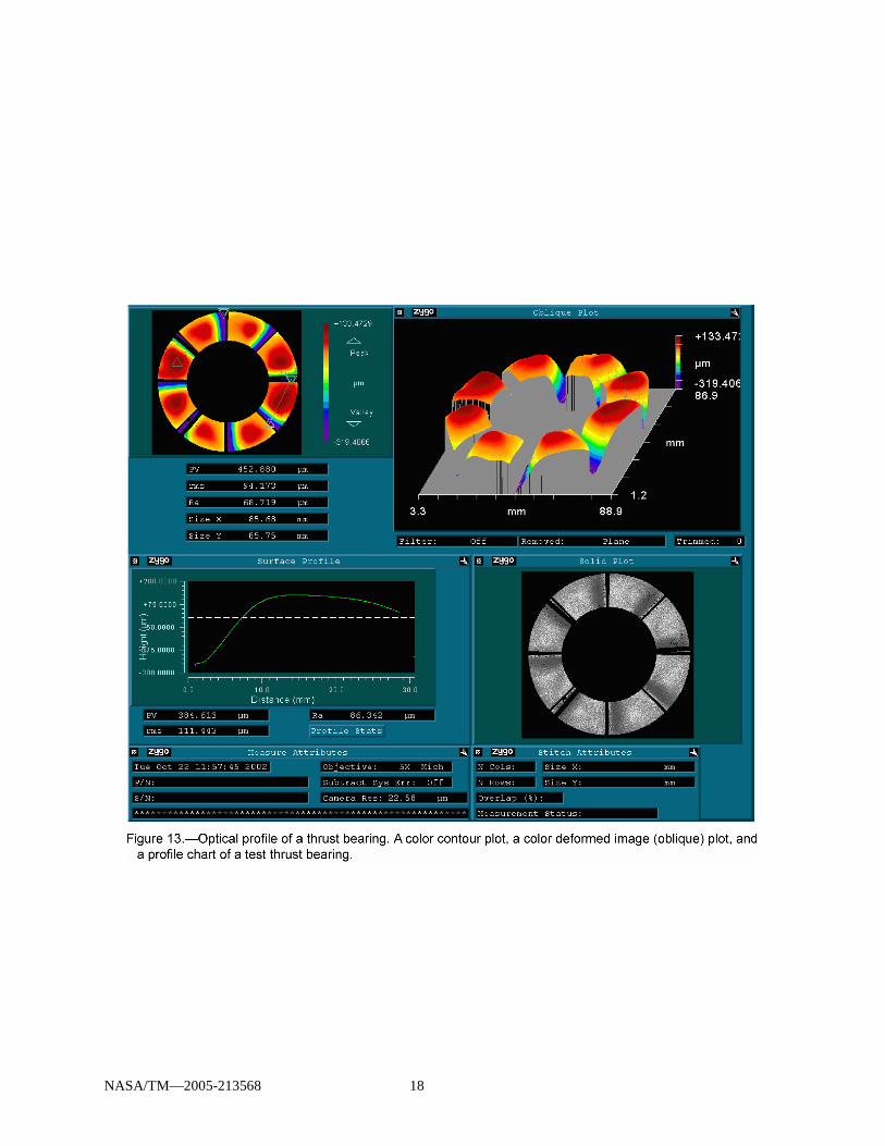
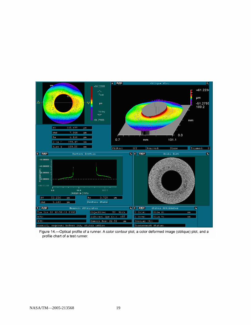
Prior to installation, the test thrust foil bearing and the runner are characterized (measured) using a noncontact, white-light-based interferometer surface profilometer. This instrument can determine the surface geometry of the specimens, calculate surface roughness and, for the thrust bearings, evaluate the uniformity of the thrust bearing petal geometry. Figure 13 shows an optical profile of a thrust bearing prior to testing. This figure includes a color contour plot, a color deformed image (oblique) plot, and a profile chart. Profilometry is again used after testing to determine if any wear of the specimens occurred as a result of testing. Figure 14 shows the optical profile of a test runner after a failed bearing left metal deposited on its surface.
Because the thrust bearing test rig is a high speed rotating machine, the rig must be properly prepared with particular attention given to the mounting and mass balancing of the thrust runner (fig. 15). The runner is a round disk approximately 10 mm thick with a diameter up to 108 mm. The runner is precision machined with concentricity and flatness typically within about 5 microns of the rotating axis. Prior to mounting, the runner is component balanced (single plane) to within 7.1 × 10⁻⁶ N-m (.001 oz-in). The runner is held on the rig shaft using four component balanced bolts. The surface of the runner which operates against the thrust foil bearing may be coated with a solid lubricant and is usually polished to an average surface roughness of 0.5 microns or less.
The thrust bearing is held onto the end of the loading piston with screws (fig. 10). A ceramic insulating block is used between the bearing and the loading piston to minimize thermal conduction from the test specimen area to the loading mechanism. After the test bearing is mounted, the thrust section is positioned onto the rig housing and bolted in place. Machined surfaces assure that the test thrust bearing is properly aligned and loaded against the runner.
NASA/TM—2005-213568 5
Operation
To conduct a typical thrust bearing test, the following general steps are taken. With the test thrust runner and thrust bearing in place (as described above), the air heater/manifold is rotated up and is bolted on. All the thermocouple and pressure transducer connections are made, and air flow lines are connected.
The magnetic thrust bearing is energized, and the axial shaft position is verified with an oscilloscope. Air is supplied, to a pressure of 207 kPa (30 psi), to the hydrostatic loader piston’s radial bearings to float the loader piston. Free motion of the piston is manually verified by slightly moving and rotating the piston via the torque arm to ensure that no binding is occurring. Caution signs and safety barriers are put into place and all personnel move to the separate control room to begin the test.
Cooling air flow is applied to the magnetic bearing and the central section, and TA (thrust air) is applied. All the instrumentation is checked for proper functioning and graphical display scales. The drive turbine is then started by applying approximately 300 kPa (45 psi) air pressure. This pressure is required to overcome the static torque of the shaft radial foil bearings. Since the running torque of these journal type foil bearings is much lower than the start-up torque, the shaft accelerates quickly and the drive air pressure must be promptly reduced. For a typical test speed of 30,000 rpm the running drive turbine air pressure is 9 psi.
If elevated temperatures are desired, the heaters are activated. There are three separate heater controllers, one for each TA manifold heater and one for the test section coil heater. Typically, all three are increased at the same time, and by the same amounts. To control thermal stresses, setting changes are usually made in 167 °C (300 °F) increments or less, with several minutes in between changes. Thrust force is typically applied after rotation has begun by slowly opening the loader valve and reading the resulting load, which is scaled by the computer from a pressure reading.
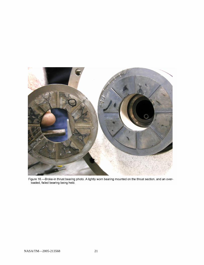
Typically, some tests are conducted to determine running torque as a function of load, speed or temperature, while other tests evaluate bearing load capacity at a given test condition (speed, temperature). Cyclic start-up and shutdown tests are designed to determine the wear rate and durability of the bearing. For these cyclic tests, an automated control system opens and closes the turbine drive air supply valve over a prescribed time sequence to simulate the starting and stopping of a turbo-machine. During starts and stops when the speed is low, no air lubricating film is present and the thrust foil bearing slides in contact with the runner surface, so wear occurs. Therefore, cyclic testing serves as an accelerated wear test, and can be used to evaluate solid lubricants for the foil bearing and runner surfaces. Figure 16 shows both a lightly worn bearing mounted on the thrust section, and an overloaded, failed bearing being held. Cyclic testing is also used as a break-in process for new foil bearing/runner specimen sets during which polishing of the mating surfaces occurs, often improving bearing load capacity (ref. 9).
Preliminary Test Results
Early test runs identified a few test rig anomalies. One is an axial shaft vibration observed during many different test conditions. This axial vibration has a magnitude of up to 0.05 mm (0.002 inches) which can have a significant effect on the test load and the results. This axial vibration occurs predominantly under low thrust bearing test loads at 11,000 and 19,000 rpm. It also occurs at higher speeds, but not as consistently. The cause for the vibration is not certain, but appears to be an artifact of interactions between the magnetic bearing controller and the thrust foil bearing/hydrostatic loader system.
The two piston ears, mentioned earlier, were used to experiment with various axial damping devices. Pairs of viscous dampers were mounted between each ear and a rigid mounting bracket attached to the table top. Several sizes of conventional carburetor-like dashpots were tried first. Later, two different sizes of “Airpot” dashpots, which are a refined piston-in-cylinder type design, were tried (fig. 17). None of these commercially available dampers appeared to make any significant difference to the axial vibration problem.
NASA/TM—2005-213568 6
Finally, coulomb friction damping was added using a “Friction Bar” design (fig. 7). Friction Bars pivot-mount to each ear and extend back where they are supported by a bracket that is mounted to the piston housing. The bar is sandwiched between shims of bronze, and the shims are point-supported (to minimize twist-binding) on set screws. Adjustment of these set screws determines the amount of clasping force on the bars, and thereby, the amount of frictional damping.
This design has not improved the registered vibration problem. However, with the rig operating and vibrating, when touching the friction bar or piston ears, the vibration can not be felt directly, but it can be felt, and heard as a hum, from the rotating section. Therefore, all the vibration may be occurring only on the rotating shaft, which is what is registered by the scope and is driven by the magnetic bearing. Ideas to damp the rotating shaft, or improve the magnetic bearing controller, are forthcoming. Further efforts are underway to better understand the cause of the vibration and to determine methods to reduce or eliminate it.
While conducting start/stop cycles to break-in new test bearings, it was noticed that for a set bearing load, the greater the TA flow rate was, the lower the resulting peak starting and stopping torques. It was later confirmed that TA pressure has a nearly proportional effect on these peak torques, which meant that it was working to un-load or “Counter Load” the bearing. There is also a direct relationship between load and TA pressure: The higher the load, the greater the pressure, which is due to the constraining of the exit passage of the air, that being between the bearing and runner. These phenomena warranted a focused investigation.
“Net Load” is the true resultant force between the bearing and the runner, and is the variable that must be accurately set and known during a test. There is no good way to measure this directly, so an indirect approach of measuring net load was conceived and executed. Consider that: Net Load = Load – Counter Load, where “Load” is the force that acts on the piston that results from applying air pressure behind the hydrostatic piston, and “Counter Load” is the unfortunate side effect of the TA pressure which acts to separate the bearing from the runner.
A new test was formulated that focused specifically on collecting data to quantify the TA Counter Load phenomenon. The only things activated were the magnetic bearing (to ensure that the runner position remained steady), the hydrostatic bearing to float the piston and bearing, and then the load and TA, which were the main variables studied. The runner was not spun, and the torque load cell and friction damper were removed for maximum piston freedom.
“Engagement Torque Force” (ETF) was measured by pulling straight up on one of the piston ears with a spring scale. The amount of force required to move the ear, which twists the bearing against the runner, was the recorded ETF. This is actually a measure of static friction between the bearing and the runner which will vary proportionally with the amount of Net Load between the two.
When the TA was off, or zero, then Net Load = Load. Therefore, it was known that the ETF measured when the TA was off represented a certain Net Load. When varying combinations of TA pressure and Load resulted in the same (or close) ETF, then this combination was resulting in the same known Net Load. The amount of Counter Load caused by the TA pressure could be calculated by: Counter Load = Load – Net Load.
Loads were varied from 0 to 116 N (26.1 lbs), and TA pressures varied from 0 to 56 kPa (8.1 psi). Of the data collected, 32 points were selected based on spotting groups having similar ETF’s, or approximately the same net loads. There are 8 different groups of 4 data points each, and the groups are graphed in figure 18. All 8 lines are nearly parallel, and all curve slightly in the same way, which confirms that good and consistent data had been collected.
An empirical relationship was sought to mathematically describe all the data, with priority given to those data groups that appear especially consistent. The best-fit equation derived is: B = Y – (1.0645) X – (.007018) X2 where B = Net Load (N), X = TA pressure (kPa) and Y = load (N) [or, B = Y – (1.65) X – (.075) X2 where B = Net Load (lbs), X = TA pressure (psi) and Y = load (lbs)]. This equation was used to create charts for use in the lab so that it can be determined what net loads result from various load and TA pressure combinations. A single graph was also devised (fig.19). Given a TA Pressure (x-axis),

NASA/TM—2005-213568 7
the graph will provide the Counter Load, and the Counter Load is subtracted from the Load setting to give the Net Load.
Due to these findings, the data acquisition programming of the controller will eventually be altered to add a “Net Load” readout. It may also be a graphical readout, probably superimposed onto the current “Load” graph. Also, the “Load” manual air valve may be replaced with a computer controlled electrically operated valve. Software will allow the rig operator to set the desired Net Load into the controller, and the computer, considering the TA pressure, will then vary the Load valve to maintain this Net Load.
Concluding Remarks
The thrust bearing test rig is a valuable tool for the development of thrust foil bearing technology. Using this facility, thrust foil bearings can be evaluated to determine their friction, load capacity and durability characteristics. Tests can be conducted under the high speed and high temperature conditions expected to be encountered in future turbine applications. The data generated by this rig can be used to corroborate developing analytical performance models, aid technology application, and to offer direct guidance for further bearing development. As more research is conducted with the rig it will be modified and improved and is expected to be a research asset for the foreseeable future.
References
1. DellaCorte, C., “A New Foil Air Bearing Test Rig for Use to 700 °C and 70,000 rpm”, NASA TM-107405, September, 1997.
2. Suriano, F.J.:”Gas Foil Bearing Development Program”, U.S. Airforce Report #AFWAL-TR-81-2095, September 1981.
3. Advanced Gas Turbine (AGT) Technology Development Project-Final Report, NASA CR-180891, December 1987. T. Strom Program Manager.
4. DellaCorte, C. and Pinkus, O., “Tribological Limitations in Gas Turbine Engines, A Workshop to Identify the Challenges and Set Future Directions”, NASA/TM–2000-210059, May, 2000.
5. Hryniewicz, P., Locke, D. and Heshmet, H., “New-Generation Development Rigs for Testing High-Speed Air-Lubricated Thrust Bearings”. Tribology Transactions, 46 (4), pp. 556–569, (2003).
6. Howard, S.A.: ”Preliminary Development of Characterization Methods for Compliant Air Bearings.” STLE Tribology Transactions, Vol. 42 (1999), 4, pp. 789–794.
7. DellaCorte, C., Lukaszewicz, V., Valco, M.J., Radil, K.C., and Heshmat, H.: “Performance and Durability of High Temperature Foil Air Bearings for Oil-Free Turbomachinery, “NASA/TM–2000-209187-REV1, March, 2000.
8. U.S. Patent 4,277,111 Gray and Hesmut, July 7, 1981. 9. Radil, K.C. and DellaCorte, C.: “The Effect of Journal Roughness and Foil Coatings on the
Performance of Heavily Loaded Foil Air Bearings.” STLE Tribology Transactions, Vol. 45 (2002), 2, pp. 199–204.

NASA/TM—2005-213568 8

NASA/TM—2005-213568 9

NASA/TM—2005-213568 10

NASA/TM—2005-213568 11

NASA/TM—2005-213568 12

NASA/TM—2005-213568 13

NASA/TM—2005-213568 14

NASA/TM—2005-213568 15

NASA/TM—2005-213568 16

NASA/TM—2005-213568 17
NASA/TM—2005-213568 18
NASA/TM—2005-213568 19

NASA/TM—2005-213568 20
NASA/TM—2005-213568 21

NASA/TM—2005-213568 22

NASA/TM—2005-213568 23

This publication is available from the NASA Center for AeroSpace Information, 301–621–0390.
REPORT DOCUMENTATION PAGE
2. REPORT DATE
19. SECURITY CLASSIFICATION OF ABSTRACT
18. SECURITY CLASSIFICATION OF THIS PAGE
Public reporting burden for this collection of information is estimated to average 1 hour per response, including the time for reviewing instructions, searching existing data sources,gathering and maintaining the data needed, and completing and reviewing the collection of information. Send comments regarding this burden estimate or any other aspect of thiscollection of information, including suggestions for reducing this burden, to Washington Headquarters Services, Directorate for Information Operations and Reports, 1215 JeffersonDavis Highway, Suite 1204, Arlington, VA 22202-4302, and to the Office of Management and Budget, Paperwork Reduction Project (0704-0188), Washington, DC 20503.
NSN 7540-01-280-5500 Standard Form 298 (Rev. 2-89)Prescribed by ANSI Std. Z39-18298-102
Form ApprovedOMB No. 0704-0188
12b. DISTRIBUTION CODE
8. PERFORMING ORGANIZATION REPORT NUMBER
5. FUNDING NUMBERS
3. REPORT TYPE AND DATES COVERED
4. TITLE AND SUBTITLE
6. AUTHOR(S)
7. PERFORMING ORGANIZATION NAME(S) AND ADDRESS(ES)
11. SUPPLEMENTARY NOTES
12a. DISTRIBUTION/AVAILABILITY STATEMENT
13. ABSTRACT (Maximum 200 words)
14. SUBJECT TERMS
17. SECURITY CLASSIFICATION OF REPORT
16. PRICE CODE
15. NUMBER OF PAGES
20. LIMITATION OF ABSTRACT
Unclassified Unclassified
Technical Memorandum
Unclassified
National Aeronautics and Space AdministrationJohn H. Glenn Research Center at Lewis FieldCleveland, Ohio 44135–3191
1. AGENCY USE ONLY (Leave blank)
10. SPONSORING/MONITORING AGENCY REPORT NUMBER
9. SPONSORING/MONITORING AGENCY NAME(S) AND ADDRESS(ES)
National Aeronautics and Space AdministrationWashington, DC 20546–0001
Available electronically at http://gltrs.grc.nasa.gov
March 2005
NASA TM—2005-213568
E–15014
WBS–22–714–09–17
29
An Oil-Free Thrust Foil Bearing Facility Design, Calibration, and Operation
Steve Bauman
Oil-free; Thrust bearings; Gas turbines
Unclassified -UnlimitedSubject Category: 23
Prepared for the 58th Annual Meeting sponsored by the Society of Tribologists and Lubrication Engineers (STLE),New York, New York, April 28–May 01, 2003. Responsible person, Steve Bauman, organization code RST,216–433–3826.
New testing capabilities are needed in order to foster thrust foil air bearing technology development and aid its transitioninto future Oil-Free gas turbines. This paper describes a new test apparatus capable of testing thrust foil air bearings up to100 mm in diameter at speeds to 80,000 rpm and temperatures to 650 °C (1200 °F). Measured parameters include bearingtorque, load capacity, and bearing temperatures. This data will be used for design performance evaluations and forvalidation of foil bearing models. Preliminary test results demonstrate that the rig is capable of testing thrust foil airbearings under a wide range of conditions which are anticipated in future Oil-Free gas turbines. Torque as a function ofspeed and temperature corroborates results expected from rudimentary performance models. A number of bearings wereintentionally failed with no resultant damage whatsoever to the test rig. Several test conditions (specific speeds and loads)revealed undesirable axial shaft vibrations which have been attributed to the magnetic bearing control system and are understudy. Based upon these preliminary results, this test rig will be a valuable tool for thrust foil bearing research, parametricstudies and technology development.