An Introduction to the Mechanics of 3D-Woven Fibre Reinforced ...
40
An Introduction to the Mechanics of 3D-Woven Fibre Reinforced Composites FREDRIK STIG Licentiate Thesis Stockholm, Sweden 2009
Transcript of An Introduction to the Mechanics of 3D-Woven Fibre Reinforced ...
An Introduction to the Mechanics of 3D-Woven FibreReinforced Composites
FREDRIK STIG
Licentiate ThesisStockholm, Sweden 2009
TRITA AVE 2009-20ISSN 1651-7660ISBN 978-91-7415-295-1
KTH School of Engineering SciencesSE-100 44 Stockholm
SWEDEN
Akademisk avhandling som med tillstånd av Kungl Tekniska högskolan framläggestill offentlig granskning för avläggande av teknologie licentiatexamen i lättkonstruk-tioner Fredagen den 8 maj 2009 klockan 13.15 i S40, Teknikringen 8, Kungl Tekniskahögskolan, Stockholm.
© Fredrik Stig, april 2009
Tryck: Universitetsservice US AB
iii
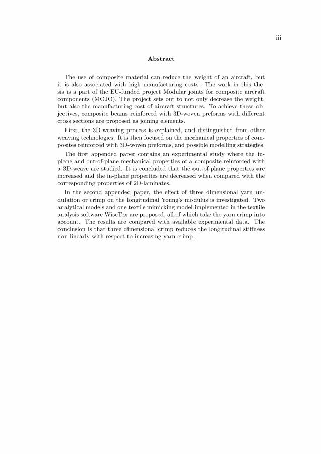
Abstract
The use of composite material can reduce the weight of an aircraft, butit is also associated with high manufacturing costs. The work in this the-sis is a part of the EU-funded project Modular joints for composite aircraftcomponents (MOJO). The project sets out to not only decrease the weight,but also the manufacturing cost of aircraft structures. To achieve these ob-jectives, composite beams reinforced with 3D-woven preforms with differentcross sections are proposed as joining elements.
First, the 3D-weaving process is explained, and distinguished from otherweaving technologies. It is then focused on the mechanical properties of com-posites reinforced with 3D-woven preforms, and possible modelling strategies.
The first appended paper contains an experimental study where the in-plane and out-of-plane mechanical properties of a composite reinforced witha 3D-weave are studied. It is concluded that the out-of-plane properties areincreased and the in-plane properties are decreased when compared with thecorresponding properties of 2D-laminates.
In the second appended paper, the effect of three dimensional yarn un-dulation or crimp on the longitudinal Young’s modulus is investigated. Twoanalytical models and one textile mimicking model implemented in the textileanalysis software WiseTex are proposed, all of which take the yarn crimp intoaccount. The results are compared with available experimental data. Theconclusion is that three dimensional crimp reduces the longitudinal stiffnessnon-linearly with respect to increasing yarn crimp.

v
Preface
The work presented in this licentiate thesis was carried out at the Department ofAeronautical and Vehicle Engineering, School of Engineering Sciences, KungligaTekniska högskolan (KTH). Funding is provided by the European Framework pro-gram 6, project MOJO, AST5-CT-2006-030871. The financial support is gratefullyacknowledged.I would also like to express my gratitude to my supervisor Dr. Stefan Hallström
for his excellent guidance, tireless support and positive aura. The beauty of ourrelation is that we both learn from each other. I learn the art of science, andStefan the art of how to hit the perfect straight backhand. I am grateful for theopportunity to work with the new and exciting 3D-woven material, and who wouldhave thought that I could put loom builder on my resumé. Dr Nandan Khokar, theinventor of 3D-weaving, is gratefully acknowledged for introducing me to the worldof weaving.
Furthermore, many thanks to my friends and colleagues at the Division of Light-weight structures for their encouragement, and lively lunch discussions. Marianneis acknowledged for proof-reading and morale-boosting. I would especially like tothank my office room mate Chris for being my partner in our ski-building project,that started as an after-hours hobby project and ended as a course in appliedcomposites design in sports applications for the fourth year students.
Finally, I would like to thank my beloved family for your endless support andJulia, my friend inspiration and love.
Fredrik Stig
Stockholm in April 2008

vi
As this thesis may be read outside of Sweden an explanation of the Swedish Licen-tiate degree may be necessary. An intermediate academic degree called Licentiate ofTechnology can be obtained half-way between an MSc and a PhD. While less formalthan a Doctoral Dissertation, examination for the degree includes writing a thesisand a public thesis defence.
vii
Dissertation
This licentiate thesis consists of an introduction to the area of research and the twofollowing appended papers:
Paper A
Fredrik Stig and Stefan Hallström, Assessment of the mechanical properties of anew 3D woven fibre composite material, Compos. Sci. Technol., doi:10.t1016/j.compscitech. 2008.04.047, 2008.
Paper B
Fredrik Stig and Stefan Hallström, Influence of Crimp on 3D-woven Fibre Rein-forced Composites, to be submitted.

Contents
I Introduction 1
1 Background 3
2 Objective 5
3 Weaving 63.1 2D-Weaving . . . . . . . . . . . . . . . . . . . . . . . . . . . . . . . . 73.2 3D-Weaving . . . . . . . . . . . . . . . . . . . . . . . . . . . . . . . . 83.3 Noobing . . . . . . . . . . . . . . . . . . . . . . . . . . . . . . . . . . 11
4 Mechanical properties 134.1 Crimp . . . . . . . . . . . . . . . . . . . . . . . . . . . . . . . . . . . 144.2 Other mechanical properties . . . . . . . . . . . . . . . . . . . . . . . 17
5 Modelling 18
6 Contribution to the field 21
7 Future work 21
Bibliography 23
II Appended papers 29
ix


Part I
Introduction
1

An Introduction to the Mechanics of 3D-Woven Fibre Reinforced Composites 3
1 Background
Three dimensionally woven textiles are not only beautiful, they also have the po-tential to change the way aircraft and other complex structures are built.Recently both Airbus and Boeing, the two leading aircraft manufacturers, have
in their strive to reduce structural weight, dramatically increased the use of fibrereinforced composite materials in their new aircraft. The development can be ex-emplified by the new Boeing 787 Dreamliner which is the first commercial aircraftwith both composite wings and fuselage, for which the combined weight of thecomposite parts account for 50% of the structural weight [1]. This trend marksa shift from using composite materials in only secondary structures (i.e. radardomes and control surfaces etc.) to also use composites in load bearing primarystructures. However, the increased use of composite materials is associated withincreased manufacturing costs [2].
Today the "state of the art" manufacturing method for primary aircraft struc-tures made of carbon fibre reinforced plastics (CFRP), is pre-preg layup1. Themechanical properties of composites made from pre-pregs are characterised by highin-plane stiffness and strength and lower out-of-plane stiffness and strength. Ac-cording to Naik and Ganesh [3] the majority of primary loads in aircraft structuresare in-plane, and hence motivate the use of pre-preg laminates. The fuselage is oneexample where this is true. However, in parts such as stiffeners and stringers notall loads are in-plane, making the pre-preg laminate with its low out-of-plane lam-ina stiffness and strength less suitable. Composite materials with better through-thickness mechanical properties are thus desired to substitute today’s metal partswhere such loads occur.Composites reinforced with net-shaped three dimensional (3D)-fabric pre-forms
have emerged as a viable option for parts like stiffeners and stringers. The 3D-fabricwas developed in the 1970’s [4], and is characterised by yarns oriented not onlyin-plane but also in the through-thickness direction, resulting in higher through-thickness strength and stiffness. That 3D-fabric reinforcement can overcome theproblems of low inter-laminar and through-thickness strength typical for traditional2D-laminates has been known for many years, and was pointed out by Kregers andMelbardis [5] already in 1978.
The driving forces for using 3D-fabrics instead of 2D-fabrics as reinforcementin composite materials are not only their increased through-thickness properties.Other benefits include [4, 6–8]:
• The option of using different types of yarns in different directions
• Flexible fibre orientation and fabric architecture1Pre-preg is short for pre-impregnated and indicate that the fibres are impregnated with partly
hardened resin. After the pre-preg is laid up, the composite part is cured using heat and elevatedpressure
4 Fredrik Stig
• Higher impact tolerance
• Lower manufacturing costs due to reduced labour intensity in the manufac-turing processes.
The work described in this thesis is a part of the EU-funded project Modularjoints for composite aircraft components (MOJO)2. The MOJO project was initi-ated in order to find strategies to meet future requirements of increased use of fibrereinforced composites in the primary load bearing aircraft structures. Many of theleading European aerospace companies, such as EADS Innovation Works, PremiumAEROTEC, Dassault aviation, Eurocopter and Sabca, are involved together withthe composite manufacturer Secar, the weaving innovation company Biteam, theresearch institutes DLR and CRC-ACS, VZLU and the University of Patras as wellas KTH. Biteam contributes to the project with the novel 3D-weaving technology.The objective of the MOJO project is to develop more integral composite aircraft
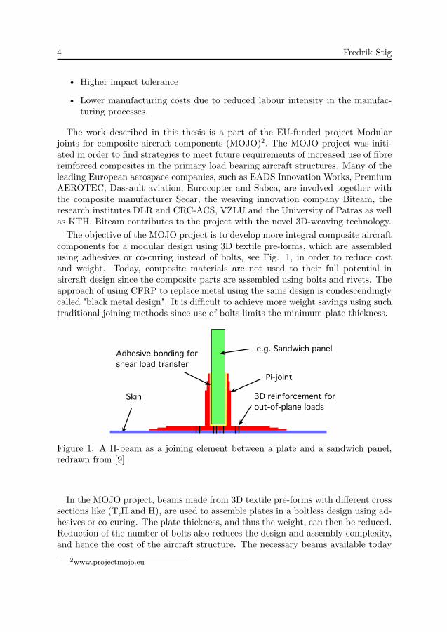
components for a modular design using 3D textile pre-forms, which are assembledusing adhesives or co-curing instead of bolts, see Fig. 1, in order to reduce costand weight. Today, composite materials are not used to their full potential inaircraft design since the composite parts are assembled using bolts and rivets. Theapproach of using CFRP to replace metal using the same design is condescendinglycalled "black metal design". It is difficult to achieve more weight savings using suchtraditional joining methods since use of bolts limits the minimum plate thickness.
Skin
Adhesive bonding for shear load transfer
e.g. Sandwich panel
Pi-joint
3D reinforcement for out-of-plane loads
Figure 1: A Π-beam as a joining element between a plate and a sandwich panel,redrawn from [9]
In the MOJO project, beams made from 3D textile pre-forms with different crosssections like (T,Π and H), are used to assemble plates in a boltless design using ad-hesives or co-curing. The plate thickness, and thus the weight, can then be reduced.Reduction of the number of bolts also reduces the design and assembly complexity,and hence the cost of the aircraft structure. The necessary beams available today
2www.projectmojo.eu
An Introduction to the Mechanics of 3D-Woven Fibre Reinforced Composites 5
are made from traditionally 2D-woven and non-woven textiles, which have to becut, stacked and draped. There are problems associated with this methodology,the main ones being difficulty to fixate the layers to the desired shape before cur-ing, and to achieve good enough through-thickness mechanical properties of thecured parts. To improve the through-thickness properties, various forms of stitch-ing, braiding, bonding or z-pinning (a form a stapling with small carbon rods) havebeen developed, each technique having different benefits and drawbacks [10]. Oneof the methods proposed in the MOJO project to solve this issue is to use 3D-wovenpre-forms, which have structural integrity on their own, and are easily handled be-fore curing. Furthermore, the yarns are all interlaced in a network structure, seeChapter 3, with reinforcements in all directions, altering the failure mechanisms ina favourable way.
The target of the MOJO project is to reduce component manufacturing cost by20-30% and reduce weight by at least 15% compared to pre-preg designs [9]. Theweight reduction is achieved by the elimination of fasteners and the reduction ofplate thickness previously governed by the requirements set by the use of bolts.Cost reduction is mainly achieved by the introduction of beams as joining elementswhich eliminate the use of bolts, and thereby reduce the cost of assembly. Boeingestimates that the number of components in a metal part can be reduced by 95%when replaced with a composite part [1]. Furthermore, the cost of manufacturingthe joining elements depends on the manufacturing method. The use of dry textilepre-forms in an out-of-autoclave3 vacuum assisted impregnation process in an openmould is less expensive than using pre-preg in an autoclave. In addition, the weightsavings achieved also decrease the in-service cost for the airline operators, whencompared to current metal designs [9].
2 Objective
The main aims of the work undertaken at KTH in the MOJO project are twofold.Firstly, it involves the design and construction of a 3D-weaving loom. Secondly,the characteristics of composite materials reinforced with 3D-woven pre-forms areto be investigated, to be able to predict and tailor the mechanical properties of thisnovel material. The objective of this thesis is to contribute to this knowledge base.The thesis consists of two appended papers with the following objectives:
• Paper A addresses the mechanical properties of a composite material rein-forced with 3D-weave by performing the following tests; tensile, compression,short-beam shear, out-of-plane and flexural test.
3high temperature and high pressure chamber for curing composites. Commonly used forcuring pre-preg laminates
6 Fredrik Stig
• Paper B describes how three dimensional crimp influences the longitudinalYoung’s modulus by developing both an analytical and a textile mimickingmodel and examining the effects of yarn crimp.
3 Weaving
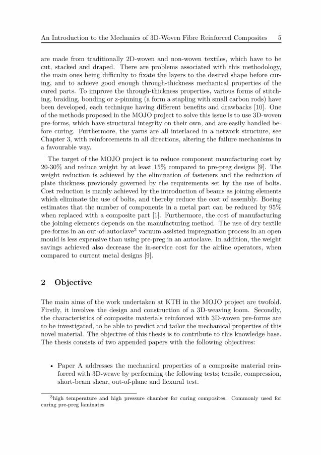
Textile manufacturing processes are broadly grouped into four types - weaving,braiding, knitting and non-wovens [11]. Each of these processes is further sub-divided according to certain processing characteristics. It is possible to manufac-ture 3D-fabrics using all of these techniques. However, this chapter focuses onweaving, and the aim is to give a brief overview of the two fundamentally differentmethods of weaving processes in reference to production of woven 3D-fabrics. Inthe composite materials’ industry today more than one type of weave structureare labelled 3D-woven. Khokar [12–14] therefore distinguished between 2D-woven3D-fabrics (i.e. produced by conventional 2D-weaving process), and 3D-woven 3D-fabrics (i.e. produced by 3D-weaving process) and a new class of non-woven fabricsnamed noobed fabrics (produced by the non-woven noobing process). These threeprocesses and their products are categorised in Fig. 2, and further discussed in thefollowing sections.
!"#$%&'()*+
!"#,&-.(/0+
1"#,&-.(/0+
1"#$%&'()*+
1"#,&-.(/0+
23)#$3'%)+
233-%4+,&-.(/0+
Figure 2: Categorisation of 3D-fabrics.
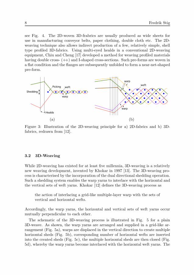
The fundamental operations constituting the weaving process are, in their se-quential order, shedding, picking, beating up and taking up. The shedding opera-tion displaces the warp yarns using healds4 to create a shed (a gap). The variousshedding methods available have been described by Khokar [15]. The sheddingoperation is followed by the picking operation whereby the weft yarns are insertedin the created shed. The weft that is laid in the shed is beaten-up by the reed5
to the fabric-fell position, and thereby completing the fabric formation. To achievecontinuity in the process, the produced fabric is advanced forward by the take-up
4A heald is a flat steel strip or a wire, with one or more eyes in which warp yarns are threaded.5A metal comb fixed in the loom used for beating-up. The closeness of its teeth determines
the fineness of a cloth.
An Introduction to the Mechanics of 3D-Woven Fibre Reinforced Composites 7
operation. This cycle of operations are continued repeatedly to obtain the wovenfabric.In a 2D-weaving process, two mutually perpendicular sets of yarns, the warps
and the wefts, are used. The warp yarns run in the length-wise direction of thefabric, and the weft yarns in the transverse direction. This arrangement remainsunchanged whether a single warp sheet is used (to produce sheet-like 2D-fabrics) ormultiple warp sheets are used (to produce 3D-fabrics). This is because the weavingprocess continues to be identical in the production of both these fabric types.
In 3D-weaving process, one grid-like set of warp yarns and two mutually perpen-dicular sets of weft yarns are used. These two sets of weft yarns are thus denotedhorizontal wefts and vertical wefts.
In both 2D- and 3D-weaving processes, additional non-interlacing stuffer warpyarns can be included. These stuffer warp yarns do not interlace with the weftsand hence occur linearly in the woven fabric.
A variety of basic 3D-fabric architectures are producible employing the 2D- and3D-weaving processes, depending on how the warp is set up and how the sheds areformed. According to Whitney and Chou [16] the exact geometry of each of thebasic woven architectures is influenced by several weaving parameters such as:
• Fibre or tow size
• Number of warp and weft yarns per unit width and length
• Number of warp layers interlacing with each weft yarn (weave pattern)
• Tension in the warp and weft yarns
• Tightness of the tows (resistance of deforming from its original cross-sectionalshape).
3.1 2D-Weaving
Two-dimensional weaving may be utilised to produce both conventional sheet-like2D-fabrics and some 3D-fabrics. Two-dimensional weaving is characterised bymono-directional shedding, and the interlacing of two orthogonal sets of yarns.Khokar [12] defines the 2D-weaving process as
the action of interlacing either a single- or a multiple-layer warp with aset of weft.
The manner in which the 2D-weaving process is employed for producing both 2D-fabrics and 3D-fabrics is illustrated in Fig. 3.The two most common 2D-woven 3D-fabrics are the layer-to-layer angle interlock
weave and through-the-thickness angle interlock weave (also known as 3-X weave),
8 Fredrik Stig
see Fig. 4. The 2D-woven 3D-frabrics are usually produced as wide sheets foruse in manufacturing conveyor belts, paper clothing, double cloth etc. The 2D-weaving technique also allows indirect production of a few, relatively simple, shelltype profiled 3D-fabrics. Using multi-eyed healds in a conventional 2D-weavingequipment, Chiu and Cheng [17] developed a method for weaving profiled materialshaving double cross- (++) and I-shaped cross-sections. Such pre-forms are woven ina flat condition and the flanges are subsequently unfolded to form a near-net-shapedpre-form.
Healds
Picking
Shedding
warp
weftweft
warp
warp
1 1 2 121
2
1
2
1
2 6 7 4 5
5
4
3
2
1
4
3
2
1
53,7,11,15
4,8,12,16
1
2
5
6
9
13
14
10
Filler (weft)
StufferWarp
Stuffer
Filler (weft)
Warp
Filler (weft)
Stuffer
Filler (weft)
Stuffer Horizontal weft
Vertical weft
Warp
1 9 8 3 10
Stuffer
Filler (weft)
Stuffer Horizontal weft
Vertical weftWarp
12
3
12
31
23
12
3
12
3
12
3
WarpStuffer
Filler (weft)
12
3
12
3
Warp Warp
WarpStuffer
(a) (b)
Figure 3: Illustration of the 2D-weaving principle for a) 2D-fabrics and b) 3D-fabrics, redrawn from [12].
3.2 3D-Weaving
While 2D-weaving has existed for at least five millennia, 3D-weaving is a relativelynew weaving development, invented by Khokar in 1997 [13]. The 3D-weaving pro-cess is characterised by the incorporation of the dual directional shedding operation.Such a shedding system enables the warp yarns to interlace with the horizontal andthe vertical sets of weft yarns. Khokar [12] defines the 3D-weaving process as
the action of interlacing a grid-like multiple-layer warp with the sets ofvertical and horizontal wefts.
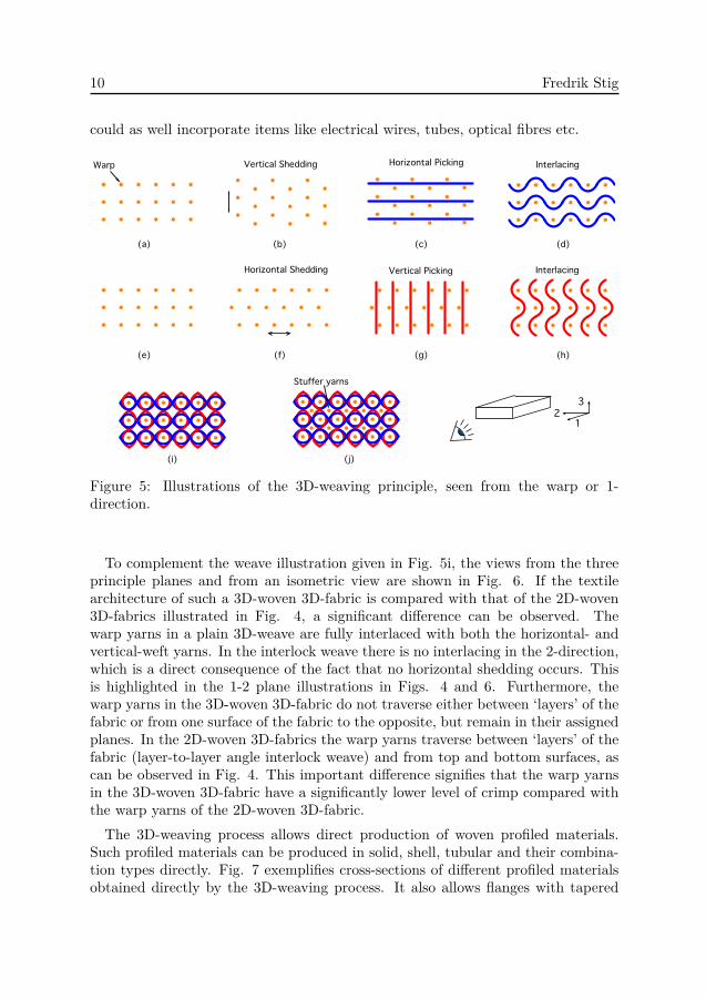
Accordingly, the warp yarns, the horizontal and vertical sets of weft yarns occurmutually perpendicular to each other.The schematic of the 3D-weaving process is illustrated in Fig. 5 for a plain
3D-weave. As shown, the warp yarns are arranged and supplied in a grid-like ar-rangement (Fig. 5a), warps are displaced in the vertical direction to create multiplehorizontal sheds (Fig. 5b), corresponding number of horizontal wefts are insertedinto the created sheds (Fig. 5c), the multiple horizontal sheds are then closed (Fig.5d), whereby the warp yarns become interlaced with the horizontal weft yarns. The
An Introduction to the Mechanics of 3D-Woven Fibre Reinforced Composites 9
1
2
3
1
2
3
1
2
3
1
2
3
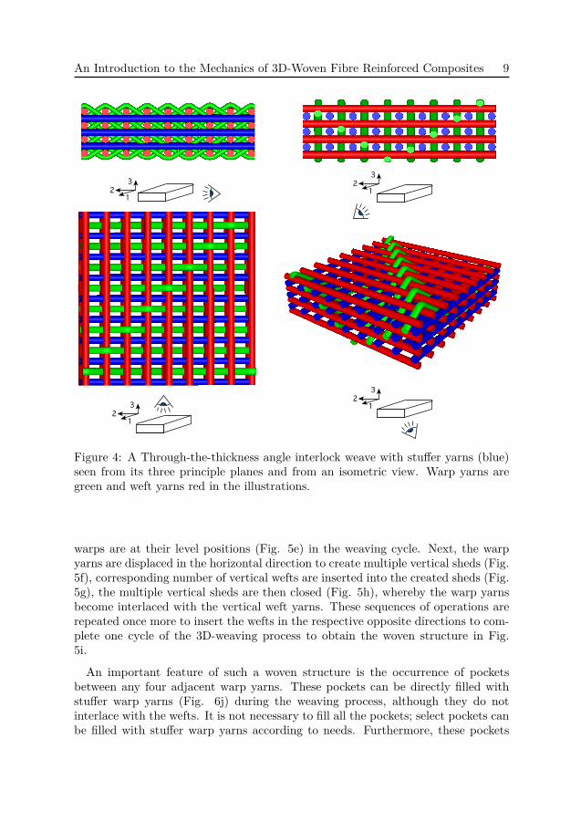
Figure 4: A Through-the-thickness angle interlock weave with stuffer yarns (blue)seen from its three principle planes and from an isometric view. Warp yarns aregreen and weft yarns red in the illustrations.
warps are at their level positions (Fig. 5e) in the weaving cycle. Next, the warpyarns are displaced in the horizontal direction to create multiple vertical sheds (Fig.5f), corresponding number of vertical wefts are inserted into the created sheds (Fig.5g), the multiple vertical sheds are then closed (Fig. 5h), whereby the warp yarnsbecome interlaced with the vertical weft yarns. These sequences of operations arerepeated once more to insert the wefts in the respective opposite directions to com-plete one cycle of the 3D-weaving process to obtain the woven structure in Fig.5i.
An important feature of such a woven structure is the occurrence of pocketsbetween any four adjacent warp yarns. These pockets can be directly filled withstuffer warp yarns (Fig. 6j) during the weaving process, although they do notinterlace with the wefts. It is not necessary to fill all the pockets; select pockets canbe filled with stuffer warp yarns according to needs. Furthermore, these pockets
10 Fredrik Stig
could as well incorporate items like electrical wires, tubes, optical fibres etc.
Stuffer yarns
Vertical SheddingWarp
Interlacing
InterlacingHorizontal Picking
Vertical PickingHorizontal Shedding
(a) (b) (c) (d)
(e) (f) (g) (h)
(i) (j)
12
3
Figure 5: Illustrations of the 3D-weaving principle, seen from the warp or 1-direction.
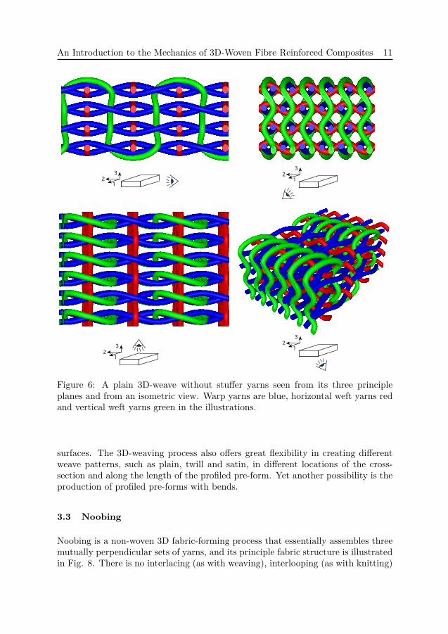
To complement the weave illustration given in Fig. 5i, the views from the threeprinciple planes and from an isometric view are shown in Fig. 6. If the textilearchitecture of such a 3D-woven 3D-fabric is compared with that of the 2D-woven3D-fabrics illustrated in Fig. 4, a significant difference can be observed. Thewarp yarns in a plain 3D-weave are fully interlaced with both the horizontal- andvertical-weft yarns. In the interlock weave there is no interlacing in the 2-direction,which is a direct consequence of the fact that no horizontal shedding occurs. Thisis highlighted in the 1-2 plane illustrations in Figs. 4 and 6. Furthermore, thewarp yarns in the 3D-woven 3D-fabric do not traverse either between ‘layers’ of thefabric or from one surface of the fabric to the opposite, but remain in their assignedplanes. In the 2D-woven 3D-fabrics the warp yarns traverse between ‘layers’ of thefabric (layer-to-layer angle interlock weave) and from top and bottom surfaces, ascan be observed in Fig. 4. This important difference signifies that the warp yarnsin the 3D-woven 3D-fabric have a significantly lower level of crimp compared withthe warp yarns of the 2D-woven 3D-fabric.
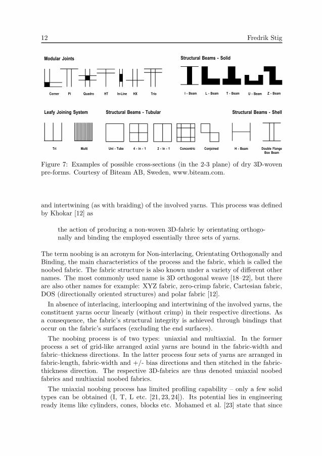
The 3D-weaving process allows direct production of woven profiled materials.Such profiled materials can be produced in solid, shell, tubular and their combina-tion types directly. Fig. 7 exemplifies cross-sections of different profiled materialsobtained directly by the 3D-weaving process. It also allows flanges with tapered
An Introduction to the Mechanics of 3D-Woven Fibre Reinforced Composites 11
1
2
3
1
2
3
1
2
3
1
2
3
Figure 6: A plain 3D-weave without stuffer yarns seen from its three principleplanes and from an isometric view. Warp yarns are blue, horizontal weft yarns redand vertical weft yarns green in the illustrations.
surfaces. The 3D-weaving process also offers great flexibility in creating differentweave patterns, such as plain, twill and satin, in different locations of the cross-section and along the length of the profiled pre-form. Yet another possibility is theproduction of profiled pre-forms with bends.
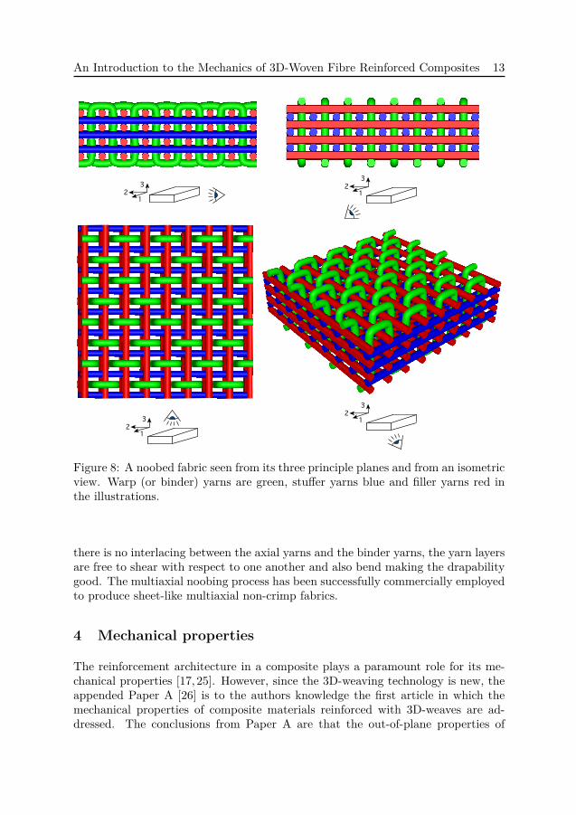
3.3 Noobing
Noobing is a non-woven 3D fabric-forming process that essentially assembles threemutually perpendicular sets of yarns, and its principle fabric structure is illustratedin Fig. 8. There is no interlacing (as with weaving), interlooping (as with knitting)
12 Fredrik Stig!"#$%&'()*+,%-%.'/)0.)1*2)3445)
!"#$%"$#&' ()&*+ , !-'./
0 , ()&* 1 , ()&* 2 , ()&* 3 , ()&*4 , ()&*5. 6$&/#- 72 78 2#.-09,1.9):-#9)#
;-/$'&# <-.9"+
2#. ;$'".
1)&=> <-.9.9? !>+")*
49. , 2$@) A , .9 , B C , .9 , B :-9%)9"#.%
!"#$%"$#&' ()&*+ , 2$@$'&#
:-9D-.9)/
!"#$%"$#&' ()&*+ , !E)''
7 , ()&* F-$@') G'&9?)(-H ()&*
!"#$%&'(%)*+& $", $&)-'./&("/-'
-)0&'1*2"'3"-."412& -)2&/1)%'$5'
6789':;&0&*!""#$%&#' #( )*+,-%$!". &-/0"#1#.!-2
Figure 7: Examples of possible cross-sections (in the 2-3 plane) of dry 3D-wovenpre-forms. Courtesy of Biteam AB, Sweden, www.biteam.com.
and intertwining (as with braiding) of the involved yarns. This process was definedby Khokar [12] as
the action of producing a non-woven 3D-fabric by orientating orthogo-nally and binding the employed essentially three sets of yarns.
The term noobing is an acronym for Non-interlacing, Orientating Orthogonally andBinding, the main characteristics of the process and the fabric, which is called thenoobed fabric. The fabric structure is also known under a variety of different othernames. The most commonly used name is 3D orthogonal weave [18–22], but thereare also other names for example: XYZ fabric, zero-crimp fabric, Cartesian fabric,DOS (directionally oriented structures) and polar fabric [12].In absence of interlacing, interlooping and intertwining of the involved yarns, the
constituent yarns occur linearly (without crimp) in their respective directions. Asa consequence, the fabric’s structural integrity is achieved through bindings thatoccur on the fabric’s surfaces (excluding the end surfaces).
The noobing process is of two types: uniaxial and multiaxial. In the formerprocess a set of grid-like arranged axial yarns are bound in the fabric-width andfabric–thickness directions. In the latter process four sets of yarns are arranged infabric-length, fabric-width and +/- bias directions and then stitched in the fabric-thickness direction. The respective 3D-fabrics are thus denoted uniaxial noobedfabrics and multiaxial noobed fabrics.
The uniaxial noobing process has limited profiling capability – only a few solidtypes can be obtained (I, T, L etc. [21, 23, 24]). Its potential lies in engineeringready items like cylinders, cones, blocks etc. Mohamed et al. [23] state that since
An Introduction to the Mechanics of 3D-Woven Fibre Reinforced Composites 13
1
2
3
1
2
3
1
2
3
1
2
3
Figure 8: A noobed fabric seen from its three principle planes and from an isometricview. Warp (or binder) yarns are green, stuffer yarns blue and filler yarns red inthe illustrations.
there is no interlacing between the axial yarns and the binder yarns, the yarn layersare free to shear with respect to one another and also bend making the drapabilitygood. The multiaxial noobing process has been successfully commercially employedto produce sheet-like multiaxial non-crimp fabrics.
4 Mechanical properties
The reinforcement architecture in a composite plays a paramount role for its me-chanical properties [17, 25]. However, since the 3D-weaving technology is new, theappended Paper A [26] is to the authors knowledge the first article in which themechanical properties of composite materials reinforced with 3D-weaves are ad-dressed. The conclusions from Paper A are that the out-of-plane properties of
14 Fredrik Stig
a composite reinforced with a 3D-weave are increased, and the in-plane proper-ties are decreased, in comparison with corresponding properties of 2D-laminates.The short-beam-shear strength was measured higher than for the 2D-laminates.However, it was not possible to quantify to what extent since the 3D-reinforcmentsuppressed the desired shear failure mode in favour of crushing under the loadingnose. This is in line with work by Mohamed et al. [23] who reported that a materialreinforced with a noobed fabric with a fibre content in the out-of-plane directionof only a few percent tends to fail in crushing rather than in shear. Furthermore,Paper A concludes that the fibres in the through-thickness direction prohibitedtensile failure in the out-of-plane tensile test, and that a new test method is neededto measure the out-of-plane strength. When compared with the 2D-laminates, thein-plane stiffness and strength are reduced due to the crimp. In Paper B, theinfluence of three-dimensional yarn crimp on the mechanical properties is furtherinvestigated. The conclusion from Paper B is that the longitudinal (1-direction)Young’s modulus is decreased non-linearly with increasing crimp, and models arepresented which predict the influence from the crimp.
4.1 Crimp
Yarn undulation, or crimp, is one of the most important textile properties since ithas a strong influence on the mechanical properties of the finished composite. Thereis no unified definition of crimp. Historically, crimp has had many definitions inthe textile industry. Alexander et al. [27] conducted a literature study on differentcrimp measures and also introduced the effective crimp diameter, and the effectivewave number. The textile industry currently defines crimp as
Crimp, geometrically considered, is the percentage excess of length ofthe yarn axis over the cloth length. It is not practicable to measurethe length of the yarn axis directly and it is estimated by removing andstraightening the thread under a standard tension.
here explained by Pierce [28] in one of the pioneering works from the 1930’s ontextile geometry.There is still a variety of crimp definitions within the textile composite commu-
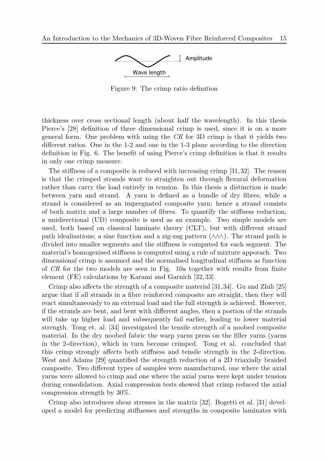
nity. The composite industry has traditionally only focused on 2D crimp, and themost common definition is the crimp ratio (CR) defined as
CR = yarn path amplitudewave length , (1)
and illustrated in Fig. 9. There are alternative ways to define crimp. West andAdams [29] defined the crimp angle as the largest rotation of the yarn from thehorizontal plane, when analysing a tri-axial 2D braided textile composite. Thecrimp ratio for a twill weave is defined by Guagliano and Riva [30] as the yarn
An Introduction to the Mechanics of 3D-Woven Fibre Reinforced Composites 15
Amplitude
Wave length
Figure 9: The crimp ratio definition
thickness over cross sectional length (about half the wavelength). In this thesisPierce’s [28] definition of three dimensional crimp is used, since it is on a moregeneral form. One problem with using the CR for 3D crimp is that it yields twodifferent ratios. One in the 1-2 and one in the 1-3 plane according to the directiondefinition in Fig. 6. The benefit of using Pierce’s crimp definition is that it resultsin only one crimp measure.The stiffness of a composite is reduced with increasing crimp [31,32]. The reason
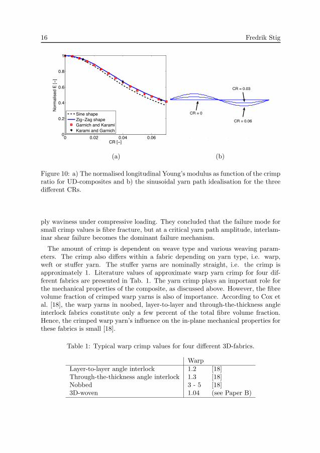
is that the crimped strands want to straighten out through flexural deformationrather than carry the load entirely in tension. In this thesis a distinction is madebetween yarn and strand. A yarn is defined as a bundle of dry fibres, while astrand is considered as an impregnated composite yarn; hence a strand consistsof both matrix and a large number of fibres. To quantify the stiffness reduction,a unidirectional (UD) composite is used as an example. Two simple models areused, both based on classical laminate theory (CLT), but with different strandpath idealisations; a sine function and a zig-zag pattern (∧∧∧). The strand path isdivided into smaller segments and the stiffness is computed for each segment. Thematerial’s homogenised stiffness is computed using a rule of mixture apporach. Twodimensional crimp is assumed and the normalised longitudinal stiffness as functionof CR for the two models are seen in Fig. 10a together with results from finiteelement (FE) calculations by Karami and Garnich [32,33].
Crimp also affects the strength of a composite material [31,34]. Gu and Zhili [25]argue that if all strands in a fibre reinforced composite are straight, then they willreact simultaneously to an external load and the full strength is achieved. However,if the strands are bent, and bent with different angles, then a portion of the strandswill take up higher load and subsequently fail earlier, leading to lower materialstrength. Tong et. al. [34] investigated the tensile strength of a noobed compositematerial. In the dry noobed fabric the warp yarns press on the filler yarns (yarnsin the 2-direction), which in turn become crimped. Tong et al. concluded thatthis crimp strongly affects both stiffness and tensile strength in the 2-direction.West and Adams [29] quantified the strength reduction of a 2D triaxially braidedcomposite. Two different types of samples were manufactured, one where the axialyarns were allowed to crimp and one where the axial yarns were kept under tensionduring consolidation. Axial compression tests showed that crimp reduced the axialcompression strength by 30%.
Crimp also introduces shear stresses in the matrix [32]. Bogetti et al. [31] devel-oped a model for predicting stiffnesses and strengths in composite laminates with
16 Fredrik Stig
0 0.02 0.04 0.060
0.2
0.4
0.6
0.8
1
CR [−]
Norm
alise
d E
[−]
Sine shapeZig−Zag shapeGarnich and KaramiKarami and Garnich
0 0.2 0.4 0.6 0.8 1
!0.3
!0.2
!0.1
0
0.1
0.2
0.3
x
y
CR = 0
CR = 0.03
CR = 0.06
(a) (b)
Figure 10: a) The normalised longitudinal Young’s modulus as function of the crimpratio for UD-composites and b) the sinusoidal yarn path idealisation for the threedifferent CRs.
ply waviness under compressive loading. They concluded that the failure mode forsmall crimp values is fibre fracture, but at a critical yarn path amplitude, interlam-inar shear failure becomes the dominant failure mechanism.The amount of crimp is dependent on weave type and various weaving param-
eters. The crimp also differs within a fabric depending on yarn type, i.e. warp,weft or stuffer yarn. The stuffer yarns are nominally straight, i.e. the crimp isapproximately 1. Literature values of approximate warp yarn crimp for four dif-ferent fabrics are presented in Tab. 1. The yarn crimp plays an important role forthe mechanical properties of the composite, as discussed above. However, the fibrevolume fraction of crimped warp yarns is also of importance. According to Cox etal. [18], the warp yarns in noobed, layer-to-layer and through-the-thickness angleinterlock fabrics constitute only a few percent of the total fibre volume fraction.Hence, the crimped warp yarn’s influence on the in-plane mechanical properties forthese fabrics is small [18].
Table 1: Typical warp crimp values for four different 3D-fabrics.
WarpLayer-to-layer angle interlock 1.2 [18]Through-the-thickness angle interlock 1.3 [18]Nobbed 3 - 5 [18]3D-woven 1.04 (see Paper B)
An Introduction to the Mechanics of 3D-Woven Fibre Reinforced Composites 17
To conclude, crimp is not favourable in a composite, since it degrades both stiff-ness and strength. On the other hand, it is not possible to weave without crimp,and 3D-fabrics possess many desirable properties for example excellent throughthickness properties, high impact tolerance and ease of handling which may lead tocost reductions [4,6–8]. In 3D-weaves crimp is also associated with yarn interlacingwhich is believed to contribute with positive effects on the mechanical performanceof composite materials.
4.2 Other mechanical properties
The integral structure of the 3D-weave where all warp yarns are interconnected withthe neighbouring horizontal and vertical weft yarns will alter failure-modes and me-chanical behaviour when compared to traditional 2D-weaves. There will also be adifference when comparing materials with different types of 3D-reinforcment, butthat comparison is more speculative and better to save for future work. Instead,a more qualitative analysis is made of how the presence of through-thickness re-inforcement influences mechanical properties of a material, in order to gain moreinsights about 3D-weave reinforced composites. For a more elaborate discussion offailure mechanisms in composites reinforced with noobed or 2D-woven 3D-fabrics ,the reader is referred to [6, 18,25,35].
One of the main advantages of 3D-fabric reinforcements is the increased fracturetoughness. The fracture toughness is a measure of how well a material containingcracks can resist fracture. Brandt et al. [36] showed an approximate ten times in-crease in the force needed to generate crack propagation in a composite reinforcedwith a noobed fabric compared to a 2D-laminate under out-of-plane loading. Bog-danovish [20] reported an increase in crack propagation resistance of 45-50 times fora noobed fabric reinforced glassfibre/epoxy-vinyl ester composite with 2.5% fibrecontent in the 3-direction (see Fig. 8) over a 2D-weave counterpart. Bogdanovishalso concluded that it was impossible to propagate a crack in a noobed fabric rein-forced carbon fibre/epoxy composite with 8% fibre content in the 3-direction.
The increased resistance to delamination also has a positive effect on compressionstrength after impact (CAI). The CAI test is important for determining the damagetolerance of a composite material. The test is performed by first dropping animpactor with a certain impact energy onto the composite, and then evaluate itscompressive strength using a compression test. Brandt et al. [36] showed thatmaterials reinforced with 3D-fabrics had a lower reduction of strength after impact,and attributed it to their increased delamination resistance given by the trough-thickness reinforcement.
Ding and Jin [37] examined the flexural fatigue properties for composites rein-forced with a 2D-woven 3D-fabric and compared it with corresponding 2D-laminates.They concluded that while delamination is the dominant fatigue failure mechanismfor 2D-laminates, the through-thickness yarn in a 2D-woven 3D-fabric preventeddelamination. Furthermore, the through-thickness yarns helped to suppress the
18 Fredrik Stig
formation of initial micro cracks and abrupt fibre failure seen in 2D-woven fabricreinforced composites. Both the 2D-laminate and the material reinforced with the2D-woven 3D-fabric showed rapid softening in the low cycle regime. In the mediumcycle regime the softening of the 2D-laminates levelled out until fibre failure, whilethe softening in 3D-fabric composites gradually increased during the entire test.Grogan et al. [38] investigated the ballistic performance of armour panels with a
ceramic strike face and a backing face reinforced with either a 2D-woven 2D-fabric ora noobed fabric. The results showed that the panels with noobed reinforcements hadless severe delamination and fewer penetrations, which was attributed to the 3D-fibre architecture. Even though the present 3D-weaving process is not yet employedto produce plates, the 3D-fibre architecture would probably increase the resistanceto ballistic impact compared to materials reinforced with 2D-weaves.
5 Modelling
A fibre reinforced composite is by nature heterogeneous on a micro scale and themechanical properties of the material are governed by its microstructure. It is, how-ever, impractical to also model the microstructure in structural engineering models.Instead, homogenised anisotropic material properties are used. The challenge is todetermine these properties, which is usually done on a meso-scale (unit cell scale).The more complex the internal geometry is, the more difficult the task will be. Fora simple cross-ply laminate CLT yields sufficiently accurate results, but as soon aswoven fabrics are used, other more intricate models are needed. According to Tonget al. [4] and Lomov et al. [39] different modelling strategies may be employed.
• Mosaic models: Are usually used to model laminates reinforced with 2D-woven 2D-fabrics, where equivalent lamina properties are computed, as ex-emplified by Ishikawa and Chou [40]
• Orienting Averaging models: The material is divided into small sub-volumeswhich are treated as UD-laminas. The homogenised properties are computedby averaging the respective stiffness matrices using either an iso-stress or iso-strain assumption. For the iso-strain assumption, a prescribed homogeneousdisplacement boundary condition is used. This means that the strains in thebuilding blocks are equal, assuming a perfect block interfacial bond [4]. Thehomogenised elastic stiffness matrix C may then be computed as
C =∑i
viCi (2)
where vi is the volume fraction and Ci the stiffness matrix of block i. Forthe iso-stress assumption, the traction (applied force) is prescribed, implyingconstant stress in the assembled building blocks. The homogenised elastic
An Introduction to the Mechanics of 3D-Woven Fibre Reinforced Composites 19
stiffness matrix is subsequently computed as
1C =
∑i
viCi. (3)
Cox et al. [41] used the orienting averaging strategy to model a compositereinforced with a 2D-woven 3D-fabric.
• Mixed iso-strain and iso-stress models: In a mixed iso-strain and iso-stressmodel, the unit cell is subdivided into sub-volumes or building blocks, in thesame way as in an Orienting Averaging model. A building block containseither UD fibre reinforced composite or pure matrix. The building blocksare assembled using either an iso-strain or an iso-stess assumption. Tan etal. [42] presented three mixed iso-strain and iso-stress models for a noobedfabric reinforced material. The analytical models developed in Paper B arealso of mixed iso-strain and iso-stress type.
• Inclusion models: The inclusion models are based on randomly dispersedinclusions in a matrix. Lomov et al. [39] point out that it is a more generalisedform of an Orienting Averaging model, but without the assumption of thesame internal average stress in all phases (or blocks). Mori and Tanaka [43]developed the theory on how to calculate the average stresses in each phase.Gommers et al. [44] used the Mori Tanaka theory and applied it to textilecomposites. One of the models in Paper B utilises an inclusion model.
• Finite element models: In a FE-model the material is divided into a largenumber of small elements, and the governing force equilibrium equations foreach element are solved simultaneously using the principle of virtual work.The elements are connected through boundary conditions, and the grid con-taining all elements is denoted a mesh. The detailed description of the internalgeometry allows for a more detailed computed stress-strain state. FE-modelscan be used with good accuracy and reliability for predicting the elastic ho-mogenised stiffness properties of textile composites, as long as the correctstrand path geometries are used and successfully meshed [19, 39]. The maindrawback with the FE-modlling technique is the need for a complex geometri-cal description of the fabric, leading to a complex mesh with many elements.
A detailed geometrical description of the internal geometry of a textile reinforcedcomposite is of great importance when modelling, regardless of strategy [45]. Theinternal architecture, i.e. the shape of the strand paths and the strand cross-sectiongeometries, may be obtained using different techniques. One technique is to usea composite sample and extract its strand paths using either a scanning electronmicroscope (SEM), an optical microscope, or a micro Computer Tomography (CT)system [46]. The first step when using an optical or scanning electron microscope isto polish the surface of the composite sample to a very fine surface finish. The next
20 Fredrik Stig
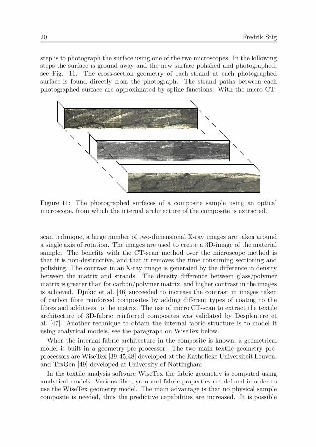
step is to photograph the surface using one of the two microscopes. In the followingsteps the surface is ground away and the new surface polished and photographed,see Fig. 11. The cross-section geometry of each strand at each photographedsurface is found directly from the photograph. The strand paths between eachphotographed surface are approximated by spline functions. With the micro CT-
Figure 11: The photographed surfaces of a composite sample using an opticalmicroscope, from which the internal architecture of the composite is extracted.
scan technique, a large number of two-dimensional X-ray images are taken arounda single axis of rotation. The images are used to create a 3D-image of the materialsample. The benefits with the CT-scan method over the microscope method isthat it is non-destructive, and that it removes the time consuming sectioning andpolishing. The contrast in an X-ray image is generated by the difference in densitybetween the matrix and strands. The density difference between glass/polymermatrix is greater than for carbon/polymer matrix, and higher contrast in the imagesis achieved. Djukic et al. [46] succeeded to increase the contrast in images takenof carbon fibre reinforced composites by adding different types of coating to thefibres and additives to the matrix. The use of micro CT-scan to extract the textilearchitecture of 3D-fabric reinforced composites was validated by Desplentere etal. [47]. Another technique to obtain the internal fabric structure is to model itusing analytical models, see the paragraph on WiseTex below.When the internal fabric architecture in the composite is known, a geometrical
model is built in a geometry pre-processor. The two main textile geometry pre-processors are WiseTex [39,45,48] developed at the Katholieke Universiteit Leuven,and TexGen [49] developed at University of Nottingham.
In the textile analysis software WiseTex the fabric geometry is computed usinganalytical models. Various fibre, yarn and fabric properties are defined in order touse the WiseTex geometry model. The main advantage is that no physical samplecomposite is needed, thus the predictive capabilities are increased. It is possible
An Introduction to the Mechanics of 3D-Woven Fibre Reinforced Composites 21
to export the geometry description to different WiseTex software packages, forinstance to TexComp where the elastic homogenised mechanical properties can becomputed using either iso-strain, iso-stress or inclusion based models. The geometrymodel can also be exported as a FE-mesh with the package FETex.In the TexGen pre-procesor the strand paths are defined using designated master
nodes. The strand path centrelines between the master nodes are interpolated usingBezier or Cubic spline functions. The surface of a strand is defined by sweeping atwo dimensional shape, for instance an ellipse, along the strand centreline. FromTexGen, the geometry model may be exported as a CAD (computer-aided design)file, or directly as a FE-mesh. However, the current FE-mesh generator in TexGenis designed for composites reinforced with 2D-weaves.
In Paper B, the textile geometry of a sample composite reinforced with a 3D-woven pre-form is obtained by using the microscope method described above. Themeasured textile architecture is used as input for both the analytical models andthe textile mimicking model. The geometrical model for the latter is constructed inTexGen, and exported to TexComp. Finally, the homogenised elastic properties arecomputed using both an inclusion model, and an orienting averaging model withan iso-strain assumption.
6 Contribution to the field
The concept of 3D-weaving is over 10 years old, however the use of 3D-wovenpre-forms as reinforcements in composite materials is new. For the concept ofcomposites reinforced with 3D-woven pre-forms to be accepted as an engineeringmaterial, the engineer must be able to understand the possibilities and limitationsassociated with the textile architecture and be able to model the material. Thisthesis contributes to both of these areas. In Paper A, an experimental study isperformed in order to present the first assessment of the mechanical properties(both in-plane and out-of-plane) of such materials. In Paper B the influentialcrimp parameter is investigated and two mechanical models are proposed.
7 Future work
Since the use of 3D-woven pre-forms in textile composites is new, there are manyopportunities for future work. However the main focus will be on modelling. Thetextile architecture of the 3D-woven fabric depends on whether the surface or theinterior of a representative volume element (RVE) is considered. How this affectsthe mechanical properties of the finished composite is one area for future work.Other interesting topics include the balance between elastic mechanical properties⇔ crimp⇔ fibre volume fraction⇔ permeability. Furthermore, one of the possiblebenefits of a fully interlaced yarn structure is increased fracture toughness, and out-

22 Fredrik Stig
of-plane strength. To quantify these parameters, new models and new experimentalapproaches are needed.
An Introduction to the Mechanics of 3D-Woven Fibre Reinforced Composites 23
Bibliography
[1] B. Griffiths. Boeing sets pace for composite usage in large civil aircraft. High Per-formance Composites, May 2005.
[2] P. Apostolopoulos and C. Kassapoglou. Recurring cost minimization of compositelaminated structures - optimum part size as a function of learning curve effects andassembly. Journal of Composite Materials, 36(4):501 – 518, 2002.
[3] N.K. Naik and V.K. Ganesh. Prediction of on-axes elastic properties of plain weavefabric composites. Composites Science and Technology, 45(2):135 – 152, 1992.
[4] L. Tong, A.P. Mouritz, and M.K. Bannister. 3D Fibre Reinforced Polymer Composite.Elsevier, 2002.
[5] A. F. Kregers and Yu. G. Melbardis. Plasticity, creep, and rheology of solids.Mekhanika Polimerov (translated), (1):3–8, 1978.
[6] P.J. Callus, A.P. Mouritz, M.K. Bannister, and K.H. Leong. Tensile properties andfailure mechanisms of 3D woven GRP composites. Composites - Part A: AppliedScience and Manufacturing, 30(11):1277 – 1287, 1999.
[7] K. Wappat. HYBRIDMAT 4: Advances in the manufacture of 3-D preform rein-forcement for advanced structural composites in aerospace – a mission to the USA.http://www.netcomposites.com/downloads/36643MR.pdf, 2006.
[8] P. Potluri and T.V. Sagar. Compaction modelling of textile preforms for compositestructures. Composite Structures, 86(1-3):177 – 185, 2008.
[9] MOJO. Modular joints for composite aircraft components contract no.: 030871.Annex I - “Description of Work”.
[10] N. Khokar. Second-generation woven profiled 3D fabrics from 3D-weaving. In FirstWorld Conference on 3D Fabrics, 2008.
[11] N. Khokar. 3D-Weaving and noobing: Characterization of interlaced and non-interlaced 3D fabric forming principles. PhD thesis, Chalmers University of Technol-ogy, 1997.
[12] N. Khokar. 3D-weaving: Theory and practice. Journal of the Textile Institute,92(1):193–207, 2001.
[13] N. Khokar. 3D fabric-forming process: Distinguishing between 2D-weaving, 3D-weaving and an unspecified non-interlacing process. Journal of the Textile Institute,87(1):97–106, 1996.
[14] N. Khokar. Noobing: A nonwoven 3D fabric-forming process explained. Journal ofthe Textile Institute, 93(1):52–74, 2002.
[15] N. Khokar. A classification of shedding methods. Journal of the Textile Institute,90(4), 1999.
[16] T.J. Whitney and T.W. Chou. Modeling of 3-D angle-interlock textile structuralcomposites. Journal of Composite Materials, 23:890–911, 1989.
24 Fredrik Stig
[17] C.H. Chiu and C.C. Cheng. Weaving method of 3D woven preforms for advancedcomposite materials. Textile Research Journal, 73(1):37–41, 2003. Woven preforms;.
[18] B.N. Cox, M.S. Dadkhah, W.L. Morris, and J.G. Flintoff. Failure mechanisms of3D woven composites in tension, compression, and bending. Acta Metallurgica etMaterialia, 42(12):3967 – 3984, 1994.
[19] J. J. Crookston, S. Kari, N. A. Warrior, I. A. Jones, and A. C. Long. 3D textilecomposite mechanical properties prediction using automated FEA of the unit cell. InProceedings of The Sixteenth International Conference on Composite Materials, July8-13, 2007: Kyoto, Japan, 2007.
[20] A. E. Bogdanovich. Advancements in manufacturing and applications of 3-D wovenpreforms and composites. In Kazuro Kageyama, Takashi Ishikawa, Nobuo Takeda,Masaki Hojo, Sunao Sugimoto, and Toshio Ogasawara, editors, Proceedings of TheSixteenth International Conference on Composite Materials, July 8-13, 2007: Kyoto,Japan, 2007.
[21] A. Hao, B. Sun, Y. Qiu, and B. Gu. Dynamic properties of 3-D orthogonal wovencomposite T-beam under transverse impact. Composites: Part A, 39(7):1073–1082,2008.
[22] S. Rudov-Clark, A.P. Mouritz, L. Lee, and M.K. Bannister. Fibre damage in themanufacture of advanced three-dimensional woven composites. Composites: Part A,34:963–970, May 2003.
[23] M. H. Mohamed, A. E. Bogdanovich, L. C. Dickinson, J. N. Singletary, and R. BradleyLienhart. A new generation of 3D woven fabric preform and composite. SAMPEJournal, 37(3):8–17, 2001.
[24] L.C. Dickinson, M.H. Mohamed, and A.E. Bogdanovich. 3D weaving: What, how,and where. In Proceedings of the 44th SAMPE Symposium, May 1999.
[25] H. Gu and Z. Zhili. Tensile behavior of 3D woven composites by using different fabricstructures. Materials and Design, 23(7):671 – 674, 2002.
[26] F. Stig and S. Hallström. Assessment of the mechanical propertiesof a new 3D woven fibre composite material. Compos. Sci. Technol.,doi:10.1016/j.compscitech.2008.04.047, 2008.
[27] E. Alexander, M. Lewin, H.V. Muhasm, and M. Shiloh. Definition and measurementof crimp of textile fibres. Textile Research Journal, 26(8):606–617, 1956.
[28] F.T. Peirce. Geometry of cloth structure. Journal of the Textile Institute, 28(3):45–96,1937.
[29] A. C. West and D. O. Adams. Axial yarn crimping effects in braided compositematerials. Journal of Composite Materials, 33:402–419, 1999.
[30] M. Guagliano and E. Riva. Mechanical behaviour prediction on plane weave compos-ites. Journal of strain analysis, 36(2):153–162, 2001.
[31] T.A. Bogetti, J.W. Gillespie JR, and M.A. Lamontia. Influence of ply waviness on thestiffness and strength reduction on composite laminates. Journal of ThermoplasticComposite Materials, 5(4):344–369, 1992.
An Introduction to the Mechanics of 3D-Woven Fibre Reinforced Composites 25
[32] M. R. Garnich and G. Karami. Finite element micromechanics for stiffness andstrength of wavy fiber composites. Journal of Composite Materials, 38(4):273–292,2004.
[33] G. Karami and M. Garnich. Effective moduli and failure considerations for compositeswith periodic fiber waviness. Composite Structures, 67:461–475, 2005.
[34] L. Tong, P. Tan, and G. P. Steven. Effect of yarn waviness on strength of 3D orthogo-nal woven CFRP composite materials. Journal of Reinforced Plastics and Composites,21(2):153, 173 2002.
[35] B.N. Cox, M.S. Dadkhah, and W.L. Morris. On the tensile failure of 3D wovencomposites. Composites - Part A: Applied Science and Manufacturing, 27(6):447 –458, 1996.
[36] J. Brandt, K. Drechsler, and F.-J Arendts. Mechanical performance of compositesbased on various three-dimensional woven-fibre preforms. Compos. Sci. Technol.(UK), 56(3):381 – 6, 1996.
[37] X. Ding and H. Jin. Flexural fatigue performance of 3D woven composites. Journalof Advanced Materials, 35(1):25–28, 2003.
[38] J. Grogan, S.A. Tekalur, A. Shukla, A. Bogdanivich, and R.A. Coffelt. Ballisticresistance of 2D and 3D woven sandwich composites. Journal of Sandwich Structuresand Materials, 9(3):283–302, 2007.
[39] S.V. Lomov, D.S. Ivanov, I. Verpoest, M. Zako, T. Kurashiki, H. Nakai, and S. Hiro-sawa. Meso-FE modelling of textile composites: Road map, data flow and algorithms.Composites Science and Technology, 67(9):1870 – 1891, 2007.
[40] T. Ishikawa and T.-W. Chou. Stiffness and strength behaviour of woven fabric com-posites. J. Mater. Sci. (UK), 17(11):3211 – 20, 1982.
[41] B.N. Cox and M.S. Dadkhah. Macroscopic elasticity of 3D woven composites. Journalof Composite Materials, 29(6):785 – 819, 1995.
[42] P. Tan, L. Tong, and G.P. Steven. Modeling approaches for 3D orthogonal wovencomposites. Journal of Reinforced Plastics and Composites, 17(6):545 – 577, 1998.
[43] T. Mori and K. Tanaka. Average stress in matrix and average elastic energy ofmaterials with misfitting inclusions. Acta Metallurgica, 21(5):571 – 574, 1973.
[44] B. Gommers, I. Verpoest, and P. van Houtte. Mori-Tanaka method applied to textilecomposite materials. Acta Materialia, 46(6):2223 – 2235, 1998.
[45] S.V. Lomov, A.V. Gusakov, G. Huysmans, A. Prodromou, and I. Verpoest. Textilegeometry preprocessor for meso-mechanical models of woven composites. CompositesScience and Technology, 60(11):2083 – 2095, 2000.
[46] W.R. Walsh L.P. Djukic, I.Herszberg and G.A. Schoeppner. Fabric and resin additivesfor contrast enhancement in visualisation of woven composite tow architecture usinga microCT scanner. Composites - Part A:, 10.1016/j.compositesa.2008.12.016, 2009.
[47] F. Desplentere, S.V. Lomov, D.L. Woerdeman, I. Verpoest, M. Wevers, and A. Bog-danovich. Micro-CT characterization of variability in 3D textile architecture. Com-posites Science and Technology 65 (2005) 1920–1930, 65:1920–1930, 2005.

26 Fredrik Stig
[48] I. Verpoest and S. V. Lomov. Virtual textile composites software WiseTex: Integra-tion with micro-mechanical, permeability and structural analysis. Composites Scienceand Technology, 65(15-16 SPEC ISS):2563 – 2574, 2005.
[49] M. Sherburn. Geometric and Mechanical Modelling of Textiles. PhD thesis, TheUniversity of Nottingham, July 2007.

An Introduction to the Mechanics of 3D-Woven Fibre Reinforced Composites 27
Division of work between authors
Paper A
Stig performed the weaving and testing and wrote the paper. Hallström initiatedand guided the work and contributed to the paper with valuable comments andrevisions.
Paper B
Stig developed the analytical and TexGen models and wrote the paper. Hallströminitiated and guided the work and contributed to the paper with valuable commentsand revisions.


Part II
Appended papers
29