An Introduction to Shader‐Based OpenGL...
152
An Introduction to Shader‐Based OpenGL Programming Ed Angel University of New Mexico [email protected] Dave Shreiner ARM, Inc. [email protected] With contributions from Evan Hart (NVIDIA) and Bill LiceaKane (AMD)
-
Upload
nguyenkien -
Category
Documents
-
view
273 -
download
0
Transcript of An Introduction to Shader‐Based OpenGL...

An Introduction to Shader‐Based OpenGL Programming
Ed Angel University of New Mexico
Dave Shreiner ARM, Inc.
With contributions from Evan Hart (NVIDIA) and Bill LiceaKane (AMD)
SIGGRAPH 2009 An Introduction to Shader-Based OpenGL Programming
ii
Table of Contents
Notes Title Page ................................................................................................................................................ 1 What Is OpenGL and What Can It Do for Me? ....................................................................................... 2 Course Ground-rules .............................................................................................................................. 3 Syllabus .................................................................................................................................................. 4 Getting Started ....................................................................................................................................... 5 The Graphics Pipeline ............................................................................................................................ 6 Steps in Pipeline .................................................................................................................................... 7 Graphic Pipeline Varieties ...................................................................................................................... 8 OpenGL Versions .................................................................................................................................. 9 Developing an OpenGL 3.1 Application .............................................................................................. 10 OpenGL and Related APIs ................................................................................................................... 11 General Structure of an OpenGL Program ........................................................................................... 12 The Simplest OpenGL Program ........................................................................................................... 13 The Simplest OpenGL Program (cont’d) ............................................................................................. 14 Drawing a Triangle - A More Realistic Example .................................................................................. 15 Loading Vertex Data ............................................................................................................................ 16 Initializing Shaders .............................................................................................................................. 17 Drawing our Triangle ........................................................................................................................... 18 The Simplest Vertex Shader ................................................................................................................. 19 The Simplest Fragment Shader ............................................................................................................ 20 Working With Objects .......................................................................................................................... 21 Representing Geometry ....................................................................................................................... 22 OpenGL’s Geometric Primitives ........................................................................................................... 23 Vertex Attributes .................................................................................................................................. 24 Vertex Arrays ....................................................................................................................................... 25 Steps for Creating Buffer Objects ........................................................................................................ 26 Storing Vertex Attributes ....................................................................................................................... 27 Storing Vertex Attributes (cont’d) .......................................................................................................... 28 “Turning on” Vertex Arrays ................................................................................................................... 29 Drawing Geometric Primitives .............................................................................................................. 30 Drawing Geometric Primitives .............................................................................................................. 31 Shaders and GLSL .............................................................................................................................. 32 Where the work gets done ................................................................................................................... 33 Vertex Shader Execution ..................................................................................................................... 34 Fragment Shader Execution ................................................................................................................ 35 OpenGL Shading Language ................................................................................................................. 36 Types and Qualifiers ............................................................................................................................ 37 Constructors ......................................................................................................................................... 38 Components ......................................................................................................................................... 39 Vector Matrix Operations ...................................................................................................................... 40 Functions .............................................................................................................................................. 41 Built-In Variables................................................................................................................................... 42 Built-in Functions .................................................................................................................................. 43 Simple Example ................................................................................................................................... 44
SIGGRAPH 2009 An Introduction to Shader-Based OpenGL Programming
iii
Application Callbacks .......................................................................................................................... 45 Vertex Shader ...................................................................................................................................... 46 Fragment Shader ................................................................................................................................. 47 Creating a Shader Program .................................................................................................................. 48 Shader Compilation (Part 1) ................................................................................................................. 49 Shader Compilation (Part 2) ................................................................................................................. 50 Shader Program Linking (Part 1) .......................................................................................................... 51 Shader Program Linking (Part 2) .......................................................................................................... 52 Using Shaders in an Application ........................................................................................................... 53 Associating Shader Variables and Data ............................................................................................... 54 Determining Shader Variable Locations .............................................................................................. 55 Initializing Uniform Variable Values ...................................................................................................... 56 Transformations ................................................................................................................................... 57 Transformations ................................................................................................................................... 58 Matrix Storage in OpenGL ................................................................................................................... 59 Camera Analogy ................................................................................................................................... 60 What Transformations Do in OpenGL ................................................................................................. 61 Specifying What You Can See ............................................................................................................. 62 Specifying What You Can See (cont’d) ................................................................................................ 63 Specifying What You Can See (cont’d) ................................................................................................ 64 The Viewport ........................................................................................................................................ 65 Viewing Transformations ...................................................................................................................... 66 Creating the LookAt Matrix ................................................................................................................... 67 Translation ............................................................................................................................................ 68 Scale ..................................................................................................................................................... 69 Rotation ................................................................................................................................................ 70 Rotation (cont’d) ................................................................................................................................... 71 Don’t Worry! ......................................................................................................................................... 72 Double Buffering ................................................................................................................................... 73 Animation Using Double Buffering ........................................................................................................ 74 Depth Buffering and Hidden Surface Removal .................................................................................... 75 Depth Buffering Using OpenGL ............................................................................................................ 76 Lighting ................................................................................................................................................ 77 Lighting Principles ................................................................................................................................ 78 OpenGL Shading .................................................................................................................................. 79 The Modified Phong Model ................................................................................................................... 80 How OpenGL Simulates Lights ............................................................................................................ 81 Surface Normals ................................................................................................................................... 82 Material Properties ............................................................................................................................... 83 Light Sources ........................................................................................................................................ 84 Light Material Tutorial ........................................................................................................................... 85 Texture Mapping .................................................................................................................................. 86 Texture Mapping ................................................................................................................................... 87 Applying Textures I .............................................................................................................................. 88 Texture Objects .................................................................................................................................... 89 Texture Objects (cont'd.) ...................................................................................................................... 90 Specifying a Texture Image .................................................................................................................. 91 Mapping a Texture ................................................................................................................................ 92 Texture Tutorial ..................................................................................................................................... 93
SIGGRAPH 2009 An Introduction to Shader-Based OpenGL Programming
iv
Texture Units ....................................................................................................................................... 94 Sampling a Texture ............................................................................................................................. 95 Texture Parameters ............................................................................................................................. 96 Filter Modes .......................................................................................................................................... 97 Mipmapped Textures ........................................................................................................................... 98 Wrapping Mode .................................................................................................................................... 99 Application Examples ........................................................................................................................ 100 Shader Examples ............................................................................................................................... 101 Height Fields ....................................................................................................................................... 102 Displaying a Height Field .................................................................................................................... 103 Time varying vertex shader ................................................................................................................ 104 Mesh Display ...................................................................................................................................... 105 Adding Lighting ................................................................................................................................... 106 Mesh Shader ...................................................................................................................................... 107 Mesh Shader (cont’d) ........................................................................................................................ 108 Mesh Shader (cont’d) ........................................................................................................................ 109 Shaded Mesh ...................................................................................................................................... 110 Cartoon Shader .................................................................................................................................. 111 Cartoon Shader ................................................................................................................................. 112 Adding a Silhouette Edge ................................................................................................................... 113 Smoothing ........................................................................................................................................... 114 Fragment Shader Examples ............................................................................................................... 115 Per-Fragment Cartoon Vertex Shader .............................................................................................. 116 Cartoon Fragment Shader ................................................................................................................. 117 Cartoon Fragment Shader Result ....................................................................................................... 118 Reflection Map .................................................................................................................................... 119 Reflection Map Vertex Shader ........................................................................................................... 120 Reflection Map Fragment Shader ...................................................................................................... 121 Reflection mapped teapot ................................................................................................................... 122 Bump Mapping .................................................................................................................................... 123 Bump Map Example ........................................................................................................................... 124 Thanks! ............................................................................................................................................... 125 Course Resources ............................................................................................................................. 126 On-Line Resources ............................................................................................................................. 127 Books .................................................................................................................................................. 128
Program Listings triangle.cxx .......................................................................................................................................... 130 color-draw-arrays.cxx ......................................................................................................................... 133 AOS-color-draw-arrays.cxx ................................................................................................................ 138 LoadProgram.h ................................................................................................................................... 146 LoadProgram.c ................................................................................................................................... 147

1
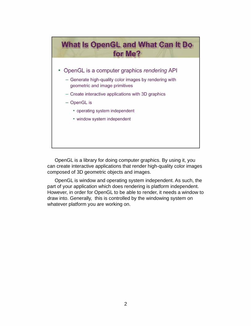
OpenGL is a library for doing computer graphics. By using it, you can create interactive applications that render high-quality color images composed of 3D geometric objects and images.
OpenGL is window and operating system independent. As such, the part of your application which does rendering is platform independent. However, in order for OpenGL to be able to render, it needs a window to draw into. Generally, this is controlled by the windowing system on y, y g ywhatever platform you are working on.
2
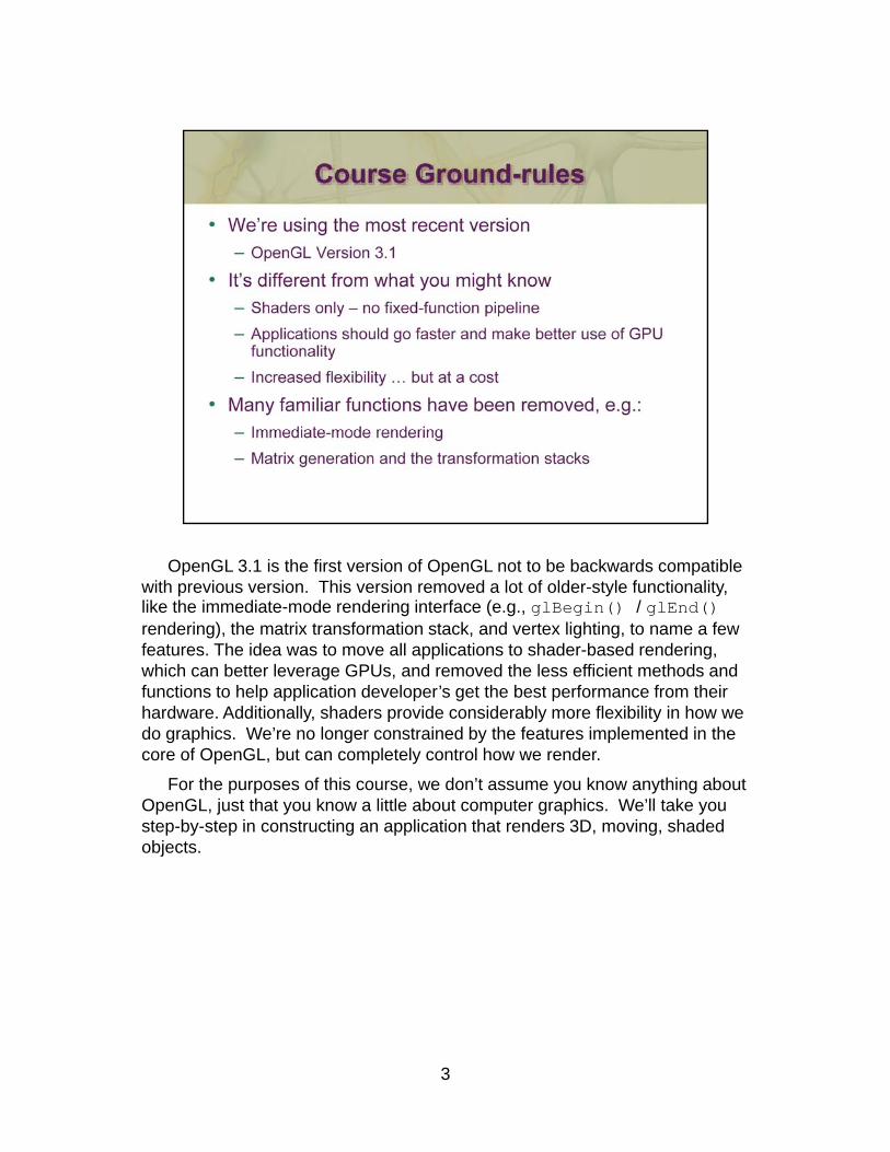
OpenGL 3.1 is the first version of OpenGL not to be backwards compatible with previous version. This version removed a lot of older-style functionality, like the immediate-mode rendering interface (e.g., glBegin() / glEnd() rendering), the matrix transformation stack, and vertex lighting, to name a few features. The idea was to move all applications to shader-based rendering, which can better leverage GPUs, and removed the less efficient methods and functions to help application developer’s get the best performance from their h d Additi ll h d id id bl fl ibilit i hhardware. Additionally, shaders provide considerably more flexibility in how we do graphics. We’re no longer constrained by the features implemented in the core of OpenGL, but can completely control how we render.
For the purposes of this course, we don’t assume you know anything about OpenGL, just that you know a little about computer graphics. We’ll take you step-by-step in constructing an application that renders 3D, moving, shaded objects.
3

4

5
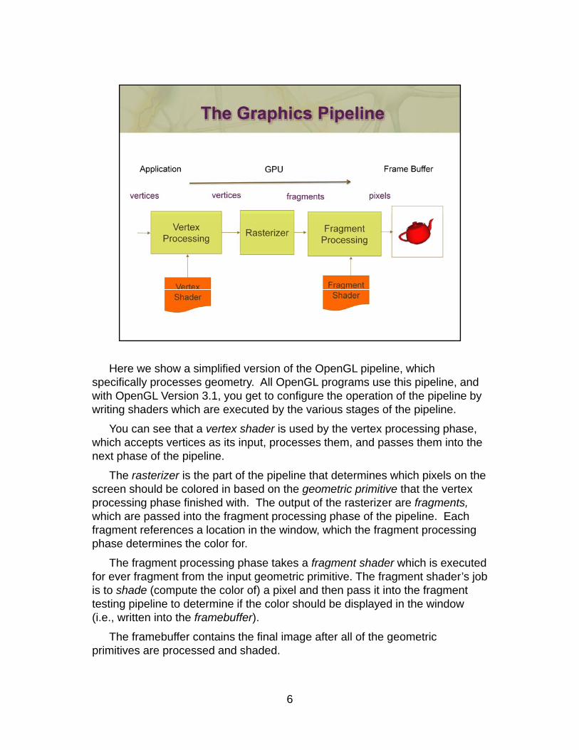
Here we show a simplified version of the OpenGL pipeline, which specifically processes geometry. All OpenGL programs use this pipeline, and with OpenGL Version 3.1, you get to configure the operation of the pipeline by writing shaders which are executed by the various stages of the pipeline.
You can see that a vertex shader is used by the vertex processing phase, which accepts vertices as its input, processes them, and passes them into the next phase of the pipeline.p p p
The rasterizer is the part of the pipeline that determines which pixels on the screen should be colored in based on the geometric primitive that the vertex processing phase finished with. The output of the rasterizer are fragments,which are passed into the fragment processing phase of the pipeline. Each fragment references a location in the window, which the fragment processing phase determines the color forphase determines the color for.
The fragment processing phase takes a fragment shader which is executed for ever fragment from the input geometric primitive. The fragment shader’s job is to shade (compute the color of) a pixel and then pass it into the fragment testing pipeline to determine if the color should be displayed in the window (i.e., written into the framebuffer).
6
The framebuffer contains the final image after all of the geometric primitives are processed and shaded.
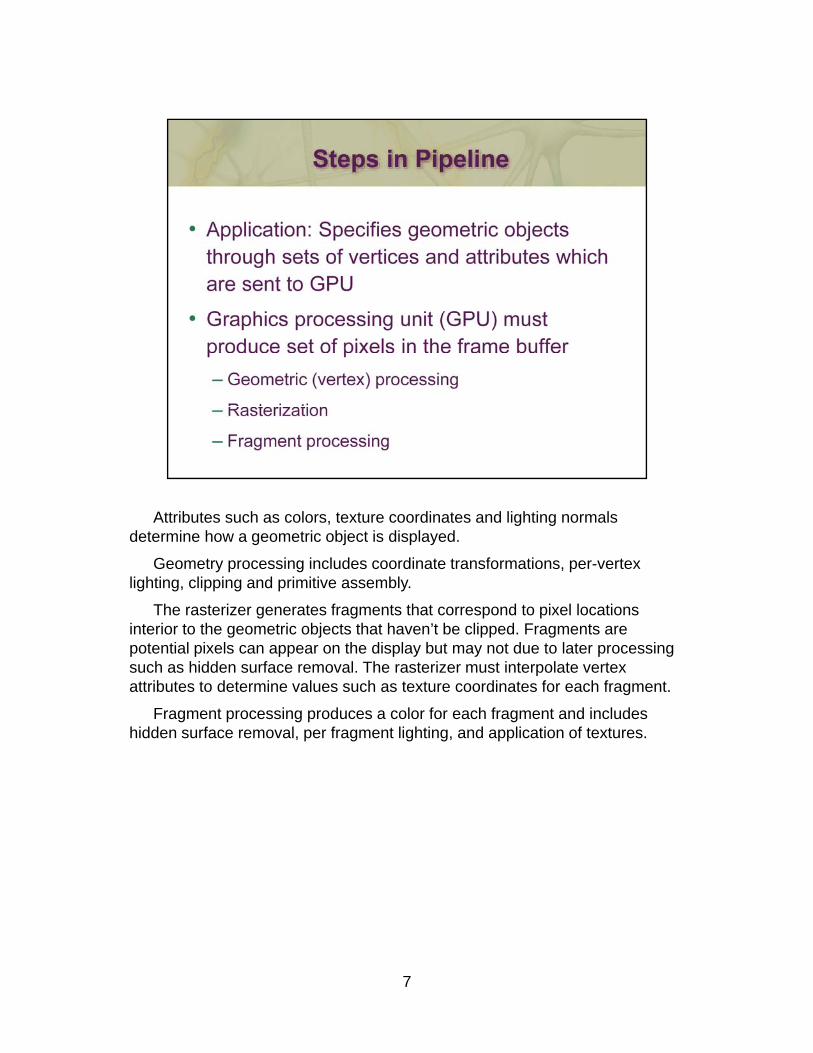
Attributes such as colors, texture coordinates and lighting normals determine how a geometric object is displayed.
Geometry processing includes coordinate transformations, per-vertex lighting, clipping and primitive assembly.
The rasterizer generates fragments that correspond to pixel locations interior to the geometric objects that haven’t be clipped. Fragments are potential pixels can appear on the display but may not due to later processingpotential pixels can appear on the display but may not due to later processing such as hidden surface removal. The rasterizer must interpolate vertex attributes to determine values such as texture coordinates for each fragment.
Fragment processing produces a color for each fragment and includes hidden surface removal, per fragment lighting, and application of textures.
7
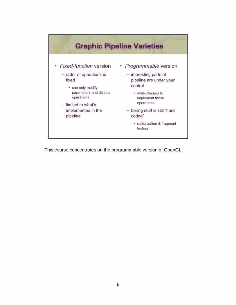
This course concentrates on the programmable version of OpenGL.
8
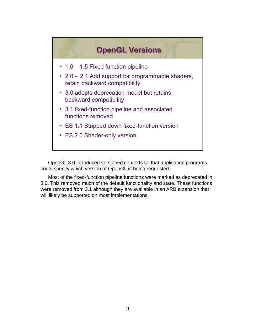
OpenGL 3.0 introduced versioned contexts so that application programs could specify which version of OpenGL is being requested.
Most of the fixed-function pipeline functions were marked as deprecated in 3.0. This removed much of the default functionality and state. These functions were removed from 3.1 although they are available in an ARB extension that will likely be supported on most implementations.
9
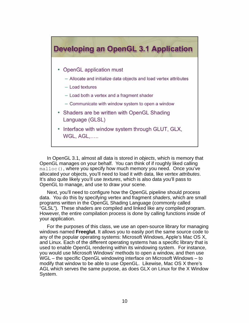
In OpenGL 3.1, almost all data is stored in objects, which is memory that OpenGL manages on your behalf. You can think of if roughly liked calling malloc(), where you specify how much memory you need. Once you’ve allocated your objects, you’ll need to load it with data, like vertex attributes. It’s also quite likely you’ll use textures, which is also data you’ll pass to OpenGL to manage, and use to draw your scene.
Next, you’ll need to configure how the OpenGL pipeline should process data You do this by specifying vertex and fragment shaders which are smalldata. You do this by specifying vertex and fragment shaders, which are small programs written in the OpenGL Shading Language (commonly called “GLSL”). These shaders are compiled and linked like any compiled program. However, the entire compilation process is done by calling functions inside of your application.
For the purposes of this class, we use an open-source library for managing windows named Freeglut. It allows you to easily port the same source code to any of the popular operating systems: Microsoft Windows, Apple’s Mac OS X, and Linux. Each of the different operating systems has a specific library that is used to enable OpenGL rendering within its windowing system. For instance, you would use Microsoft Windows’ methods to open a window, and then use WGL – the specific OpenGL windowing interface on Microsoft Windows – to modify that window to be able to use OpenGL. Likewise, Mac OS X there’s AGL which serves the same purpose, as does GLX on Linux for the X Window System.
10
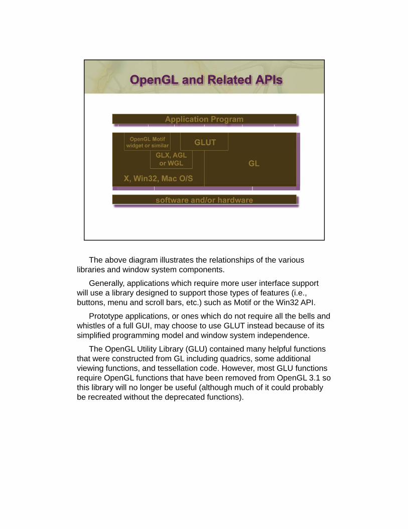
The above diagram illustrates the relationships of the various libraries and window system components.
Generally, applications which require more user interface support will use a library designed to support those types of features (i.e., buttons, menu and scroll bars, etc.) such as Motif or the Win32 API.
Prototype applications, or ones which do not require all the bells and whistles of a full GUI may choose to use GLUT instead because of itswhistles of a full GUI, may choose to use GLUT instead because of its simplified programming model and window system independence.
The OpenGL Utility Library (GLU) contained many helpful functions that were constructed from GL including quadrics, some additional viewing functions, and tessellation code. However, most GLU functions require OpenGL functions that have been removed from OpenGL 3.1 so thi lib ill l b f l ( lth h h f it ld b blthis library will no longer be useful (although much of it could probably be recreated without the deprecated functions).
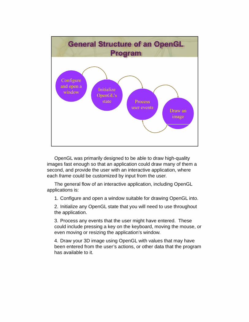
OpenGL was primarily designed to be able to draw high-quality images fast enough so that an application could draw many of them a second, and provide the user with an interactive application, where each frame could be customized by input from the user.
The general flow of an interactive application, including OpenGL applications is:
1 Configure and open a window suitable for drawing OpenGL into1. Configure and open a window suitable for drawing OpenGL into.
2. Initialize any OpenGL state that you will need to use throughout the application.
3. Process any events that the user might have entered. These could include pressing a key on the keyboard, moving the mouse, or even moving or resizing the application’s window.g g pp
4. Draw your 3D image using OpenGL with values that may have been entered from the user’s actions, or other data that the program has available to it.
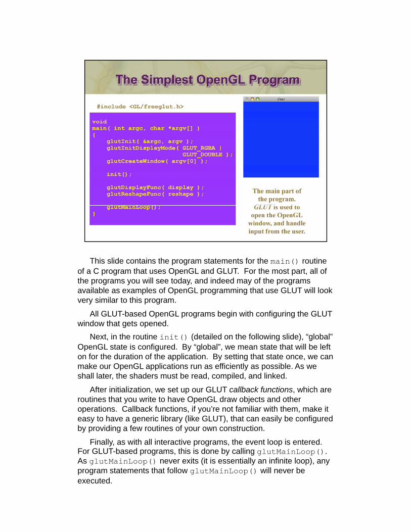
This slide contains the program statements for the main() routine of a C program that uses OpenGL and GLUT. For the most part, all of the programs you will see today, and indeed may of the programs available as examples of OpenGL programming that use GLUT will look very similar to this program.
All GLUT-based OpenGL programs begin with configuring the GLUT window that gets opened.g p
Next, in the routine init() (detailed on the following slide), “global” OpenGL state is configured. By “global”, we mean state that will be left on for the duration of the application. By setting that state once, we can make our OpenGL applications run as efficiently as possible. As we shall later, the shaders must be read, compiled, and linked.
Aft i iti li ti t GLUT llb k f ti hi hAfter initialization, we set up our GLUT callback functions, which are routines that you write to have OpenGL draw objects and other operations. Callback functions, if you’re not familiar with them, make it easy to have a generic library (like GLUT), that can easily be configured by providing a few routines of your own construction.
Finally, as with all interactive programs, the event loop is entered. For GLUT-based programs, this is done by calling glutMainLoop(). As glutMainLoop() never exits (it is essentially an infinite loop), any program statements that follow glutMainLoop() will never be executed.
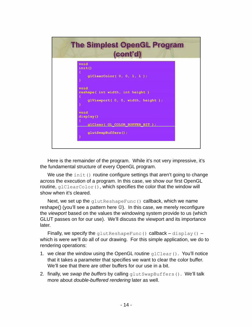
Here is the remainder of the program. While it’s not very impressive, it’s the fundamental structure of every OpenGL program.
We use the init() routine configure settings that aren’t going to change across the execution of a program. In this case, we show our first OpenGL routine, glClearColor(), which specifies the color that the window will show when it’s cleared.
Next we set up the glutReshapeFunc() callback which we nameNext, we set up the glutReshapeFunc() callback, which we name reshape() (you’ll see a pattern here ☺). In this case, we merely reconfigure the viewport based on the values the windowing system provide to us (which GLUT passes on for our use). We’ll discuss the viewport and its importance later.
Finally, we specify the glutReshapeFunc() callback – display() –hi h i ’ll d ll f d i F thi i l li ti d twhich is were we’ll do all of our drawing. For this simple application, we do to
rendering operations:1. we clear the window using the OpenGL routine glClear(). You’ll notice
that it takes a parameter that specifies we want to clear the color buffer. We’ll see that there are other buffers for our use in a bit.
2 finally we swap the buffers by calling glutSwapBuffers() We’ll talk2. finally, we swap the buffers by calling glutSwapBuffers(). We ll talk more about double-buffered rendering later as well.
- 14 -
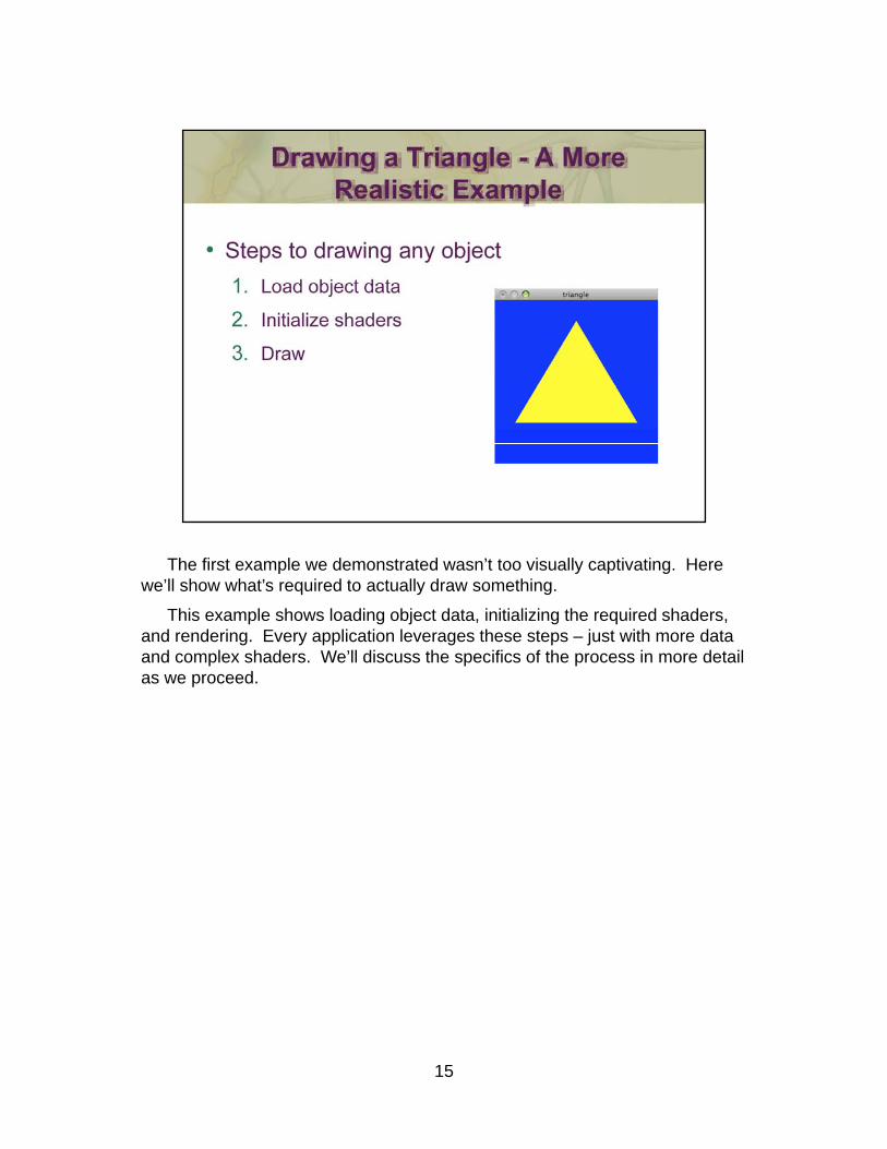
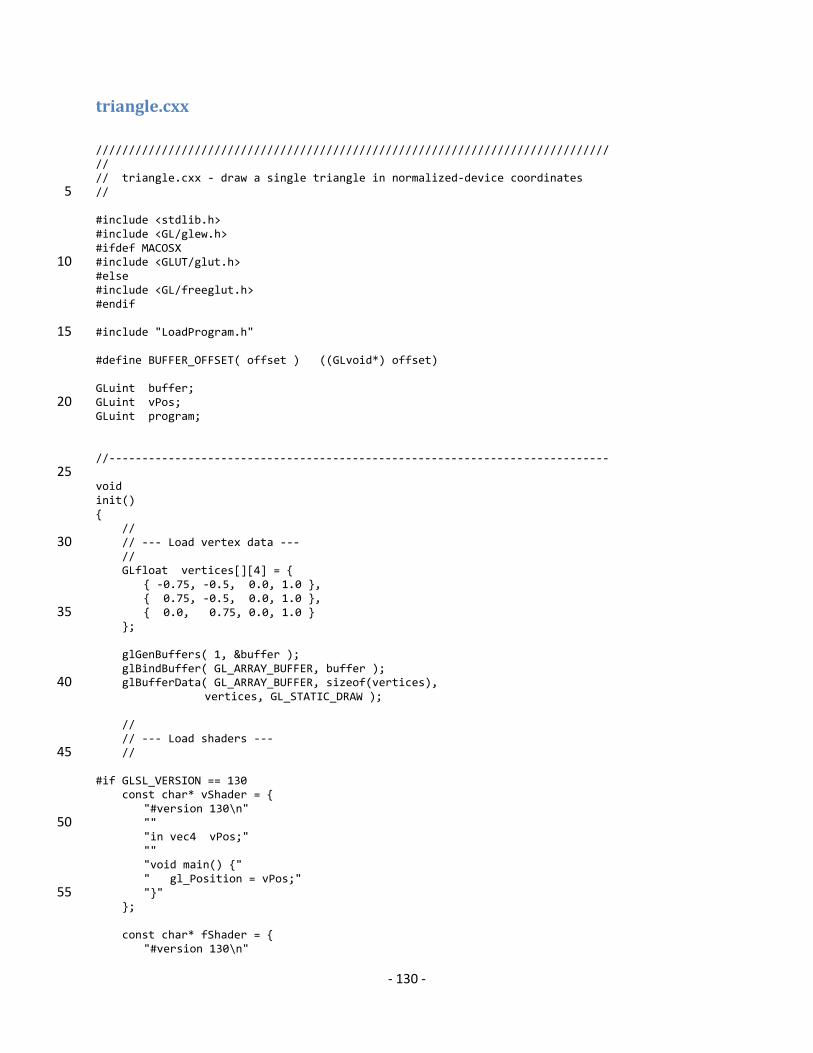
The first example we demonstrated wasn’t too visually captivating. Here we’ll show what’s required to actually draw something.
This example shows loading object data, initializing the required shaders, and rendering. Every application leverages these steps – just with more data and complex shaders. We’ll discuss the specifics of the process in more detail as we proceed.
15
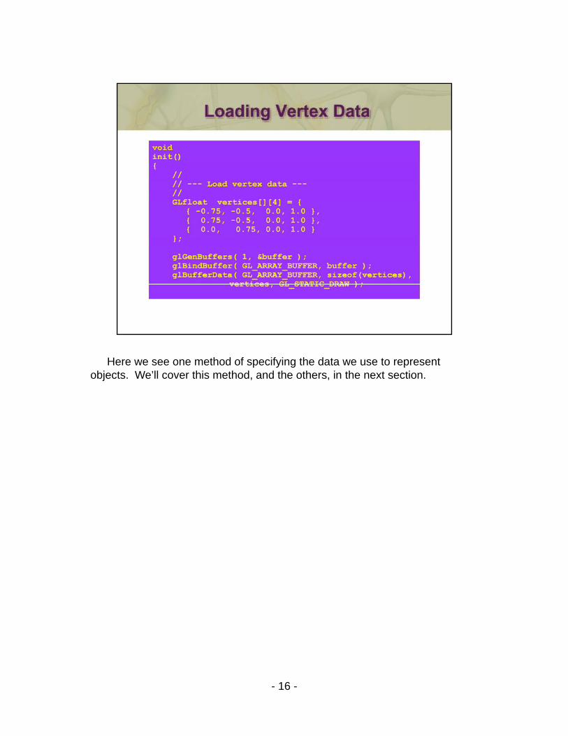
Here we see one method of specifying the data we use to represent objects. We’ll cover this method, and the others, in the next section.
- 16 -
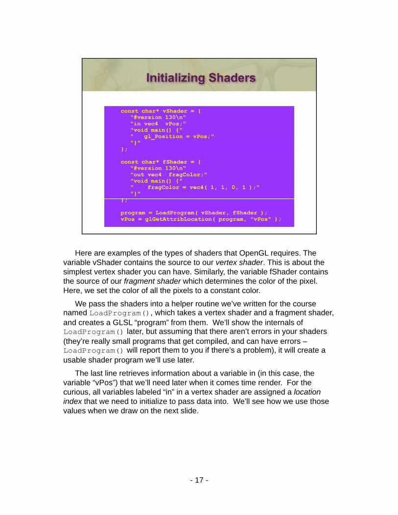
Here are examples of the types of shaders that OpenGL requires. The variable vShader contains the source to our vertex shader. This is about the simplest vertex shader you can have. Similarly, the variable fShader contains the source of our fragment shader which determines the color of the pixel. Here, we set the color of all the pixels to a constant color.
We pass the shaders into a helper routine we’ve written for the course named LoadProgram(), which takes a vertex shader and a fragment shader, g (), g ,and creates a GLSL “program” from them. We’ll show the internals of LoadProgram() later, but assuming that there aren’t errors in your shaders (they’re really small programs that get compiled, and can have errors –LoadProgram() will report them to you if there’s a problem), it will create a usable shader program we’ll use later.
The last line retrieves information about a variable in (in this case theThe last line retrieves information about a variable in (in this case, the variable “vPos”) that we’ll need later when it comes time render. For the curious, all variables labeled “in” in a vertex shader are assigned a location index that we need to initialize to pass data into. We’ll see how we use those values when we draw on the next slide.
- 17 -
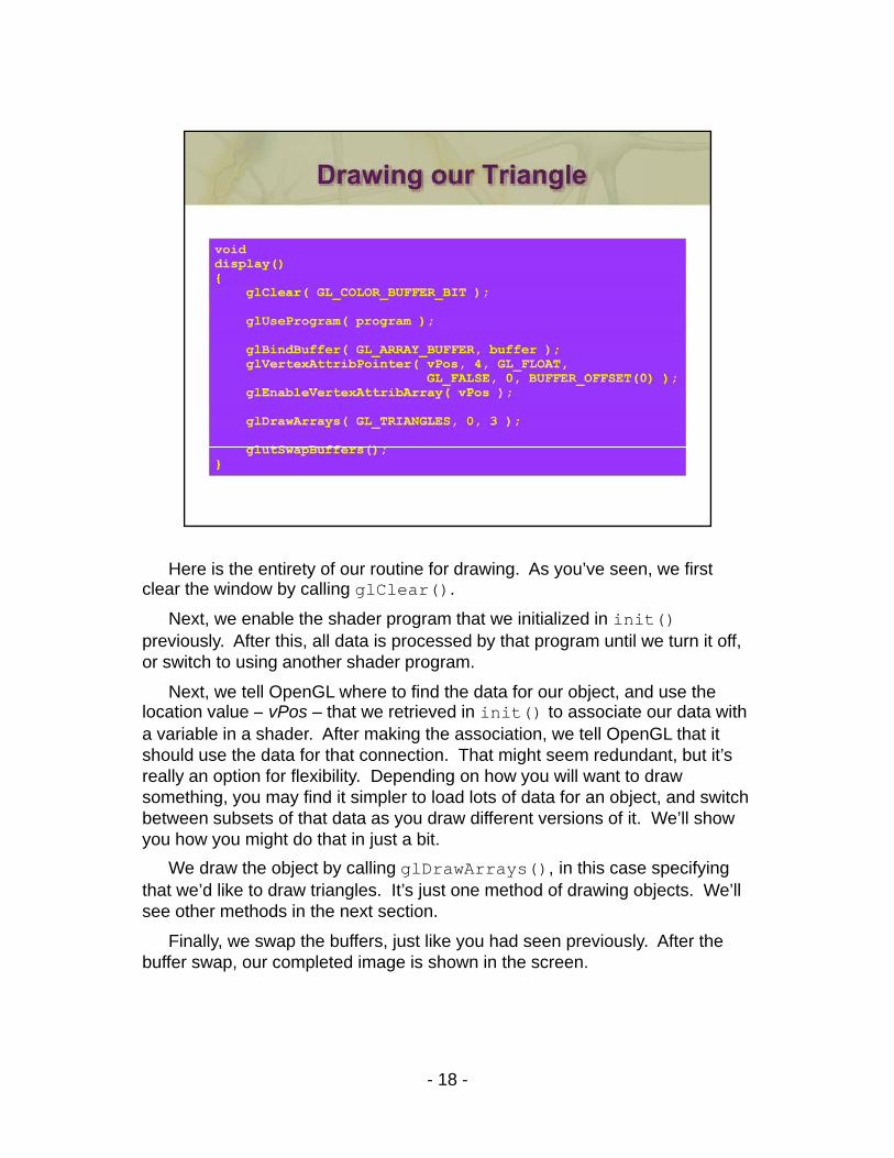
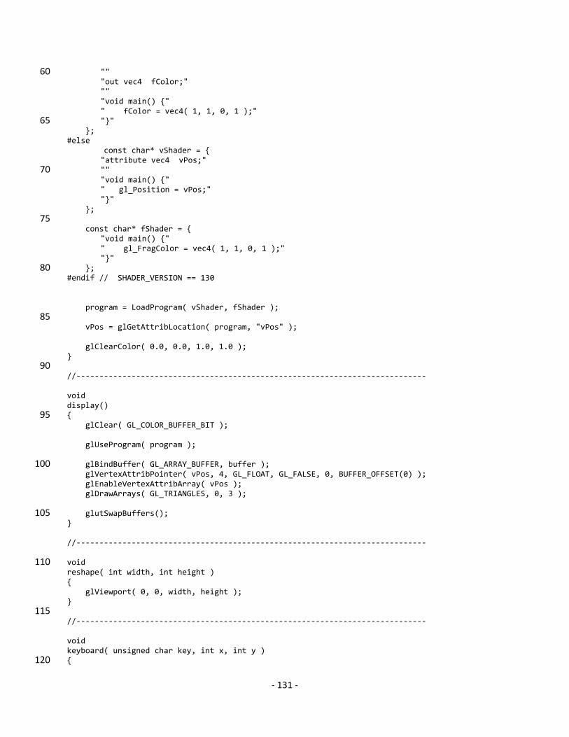
Here is the entirety of our routine for drawing. As you’ve seen, we first clear the window by calling glClear().
Next, we enable the shader program that we initialized in init() previously. After this, all data is processed by that program until we turn it off, or switch to using another shader program.
Next, we tell OpenGL where to find the data for our object, and use the location value vPos that we retrieved in init() to associate our data withlocation value – vPos – that we retrieved in init() to associate our data with a variable in a shader. After making the association, we tell OpenGL that it should use the data for that connection. That might seem redundant, but it’s really an option for flexibility. Depending on how you will want to draw something, you may find it simpler to load lots of data for an object, and switch between subsets of that data as you draw different versions of it. We’ll show you how you might do that in just a bityou how you might do that in just a bit.
We draw the object by calling glDrawArrays(), in this case specifying that we’d like to draw triangles. It’s just one method of drawing objects. We’ll see other methods in the next section.
Finally, we swap the buffers, just like you had seen previously. After the buffer swap, our completed image is shown in the screen.
- 18 -
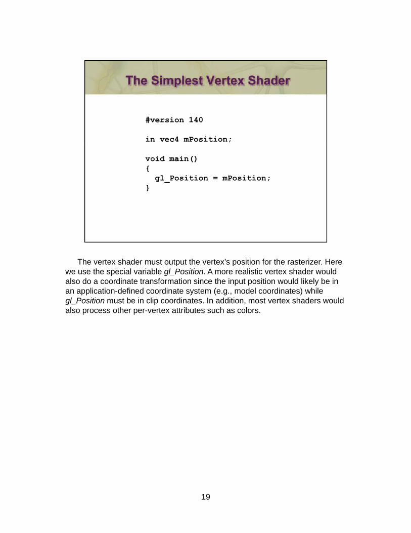
The vertex shader must output the vertex’s position for the rasterizer. Here we use the special variable gl_Position. A more realistic vertex shader would also do a coordinate transformation since the input position would likely be in an application-defined coordinate system (e.g., model coordinates) while gl_Position must be in clip coordinates. In addition, most vertex shaders would also process other per-vertex attributes such as colors.
19
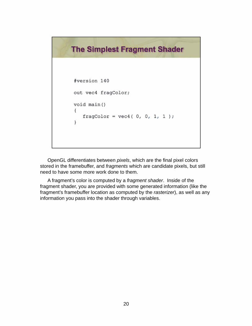
OpenGL differentiates between pixels, which are the final pixel colors stored in the framebuffer, and fragments which are candidate pixels, but still need to have some more work done to them.
A fragment’s color is computed by a fragment shader. Inside of the fragment shader, you are provided with some generated information (like the fragment’s framebuffer location as computed by the rasterizer), as well as any information you pass into the shader through variables. y p g
20

21
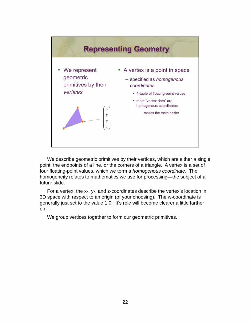
We describe geometric primitives by their vertices, which are either a single point, the endpoints of a line, or the corners of a triangle. A vertex is a set of four floating-point values, which we term a homogenous coordinate. The homogeneity relates to mathematics we use for processing—the subject of a future slide.
For a vertex, the x-, y-, and z-coordinates describe the vertex’s location in 3D space with respect to an origin (of your choosing). The w-coordinate is p p g ( y g)generally just set to the value 1.0. It’s role will become clearer a little farther on.
We group vertices together to form our geometric primitives.
22
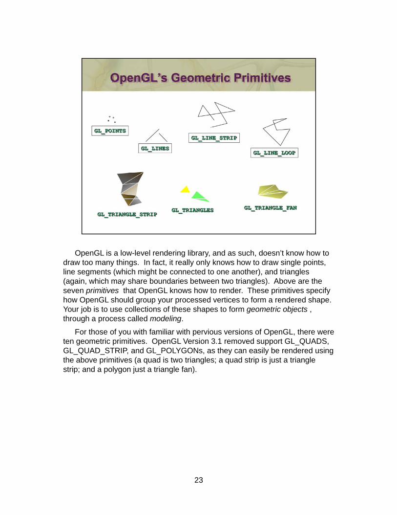
OpenGL is a low-level rendering library, and as such, doesn’t know how to draw too many things. In fact, it really only knows how to draw single points, line segments (which might be connected to one another), and triangles (again, which may share boundaries between two triangles). Above are the seven primitives that OpenGL knows how to render. These primitives specify how OpenGL should group your processed vertices to form a rendered shape. Your job is to use collections of these shapes to form geometric objects , th h ll d d lithrough a process called modeling.
For those of you with familiar with pervious versions of OpenGL, there were ten geometric primitives. OpenGL Version 3.1 removed support GL_QUADS, GL_QUAD_STRIP, and GL_POLYGONs, as they can easily be rendered using the above primitives (a quad is two triangles; a quad strip is just a triangle strip; and a polygon just a triangle fan).
23
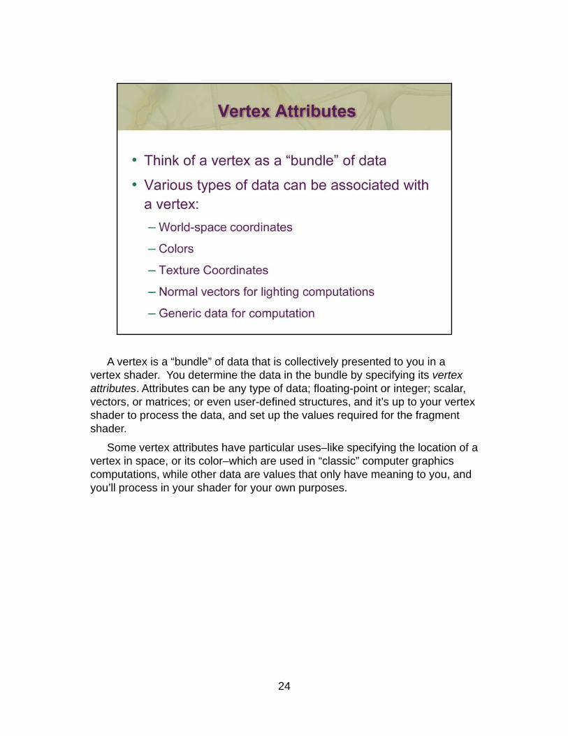
A vertex is a “bundle” of data that is collectively presented to you in a vertex shader. You determine the data in the bundle by specifying its vertex attributes. Attributes can be any type of data; floating-point or integer; scalar, vectors, or matrices; or even user-defined structures, and it’s up to your vertex shader to process the data, and set up the values required for the fragment shader.
Some vertex attributes have particular uses–like specifying the location of a p p y gvertex in space, or its color–which are used in “classic” computer graphics computations, while other data are values that only have meaning to you, and you’ll process in your shader for your own purposes.
24
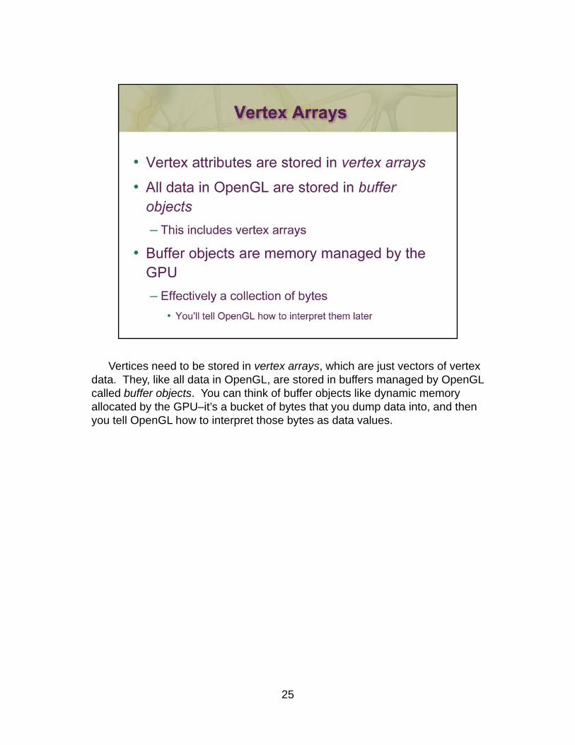
Vertices need to be stored in vertex arrays, which are just vectors of vertex data. They, like all data in OpenGL, are stored in buffers managed by OpenGL called buffer objects. You can think of buffer objects like dynamic memory allocated by the GPU–it’s a bucket of bytes that you dump data into, and then you tell OpenGL how to interpret those bytes as data values.
25
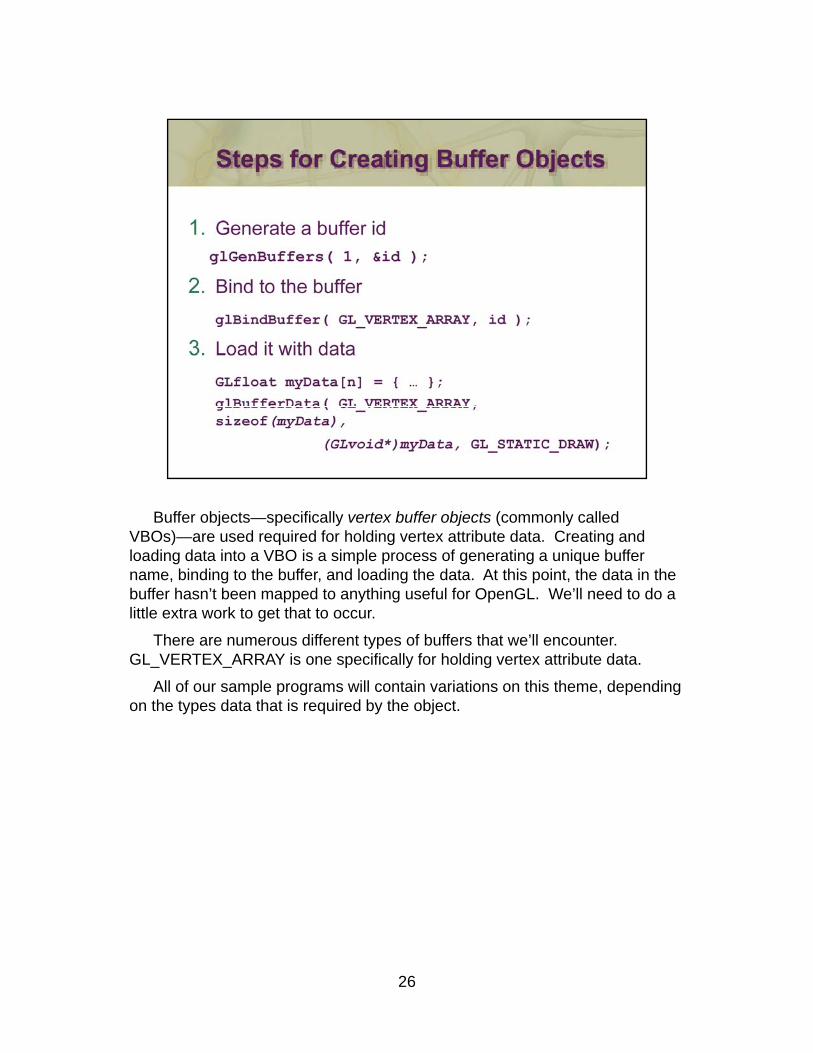
Buffer objects—specifically vertex buffer objects (commonly called VBOs)—are used required for holding vertex attribute data. Creating and loading data into a VBO is a simple process of generating a unique buffer name, binding to the buffer, and loading the data. At this point, the data in the buffer hasn’t been mapped to anything useful for OpenGL. We’ll need to do a little extra work to get that to occur.
There are numerous different types of buffers that we’ll encounter. ypGL_VERTEX_ARRAY is one specifically for holding vertex attribute data.
All of our sample programs will contain variations on this theme, depending on the types data that is required by the object.
26
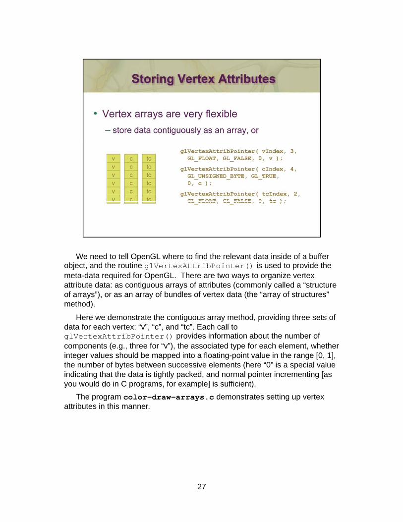
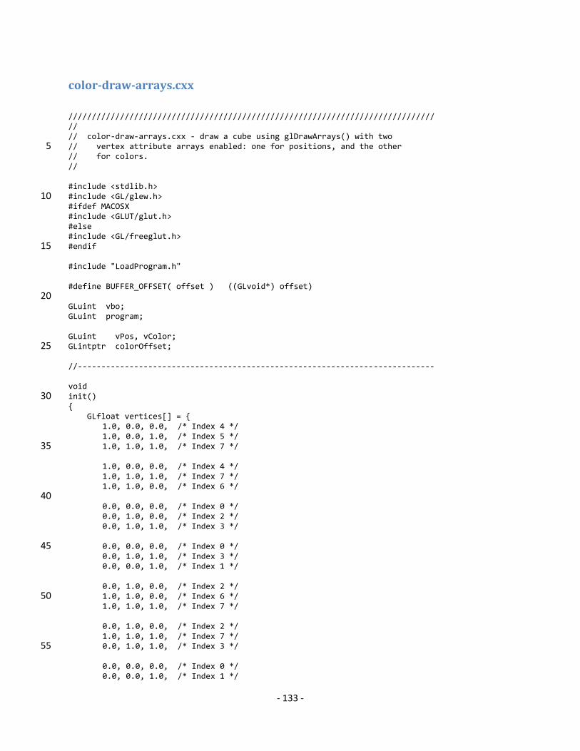
We need to tell OpenGL where to find the relevant data inside of a buffer object, and the routine glVertexAttribPointer() is used to provide the meta-data required for OpenGL. There are two ways to organize vertex attribute data: as contiguous arrays of attributes (commonly called a “structure of arrays”), or as an array of bundles of vertex data (the “array of structures” method).
Here we demonstrate the contiguous array method, providing three sets of g y , p gdata for each vertex: “v”, “c”, and “tc”. Each call to glVertexAttribPointer() provides information about the number of components (e.g., three for “v”), the associated type for each element, whether integer values should be mapped into a floating-point value in the range [0, 1], the number of bytes between successive elements (here “0” is a special value indicating that the data is tightly packed, and normal pointer incrementing [as you would do in C programs, for example] is sufficient).
The program color-draw-arrays.c demonstrates setting up vertex attributes in this manner.
27
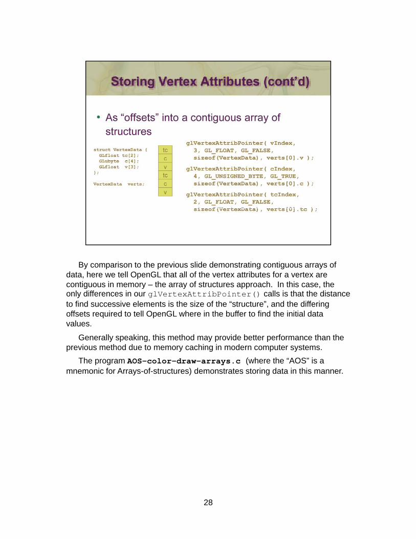
By comparison to the previous slide demonstrating contiguous arrays of data, here we tell OpenGL that all of the vertex attributes for a vertex are contiguous in memory – the array of structures approach. In this case, the only differences in our glVertexAttribPointer() calls is that the distance to find successive elements is the size of the “structure”, and the differing offsets required to tell OpenGL where in the buffer to find the initial data values.
Generally speaking, this method may provide better performance than the previous method due to memory caching in modern computer systems.
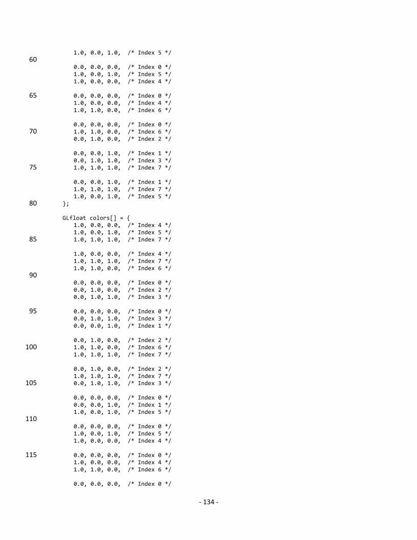
The program AOS-color-draw-arrays.c (where the “AOS” is a mnemonic for Arrays-of-structures) demonstrates storing data in this manner.
28
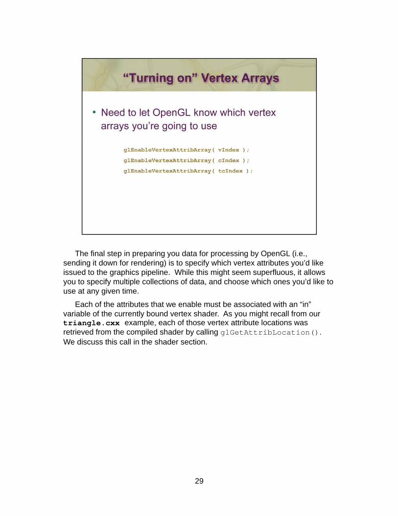
The final step in preparing you data for processing by OpenGL (i.e., sending it down for rendering) is to specify which vertex attributes you’d like issued to the graphics pipeline. While this might seem superfluous, it allows you to specify multiple collections of data, and choose which ones you’d like to use at any given time.
Each of the attributes that we enable must be associated with an “in” variable of the currently bound vertex shader. As you might recall from our y y gtriangle.cxx example, each of those vertex attribute locations was retrieved from the compiled shader by calling glGetAttribLocation(). We discuss this call in the shader section.
29
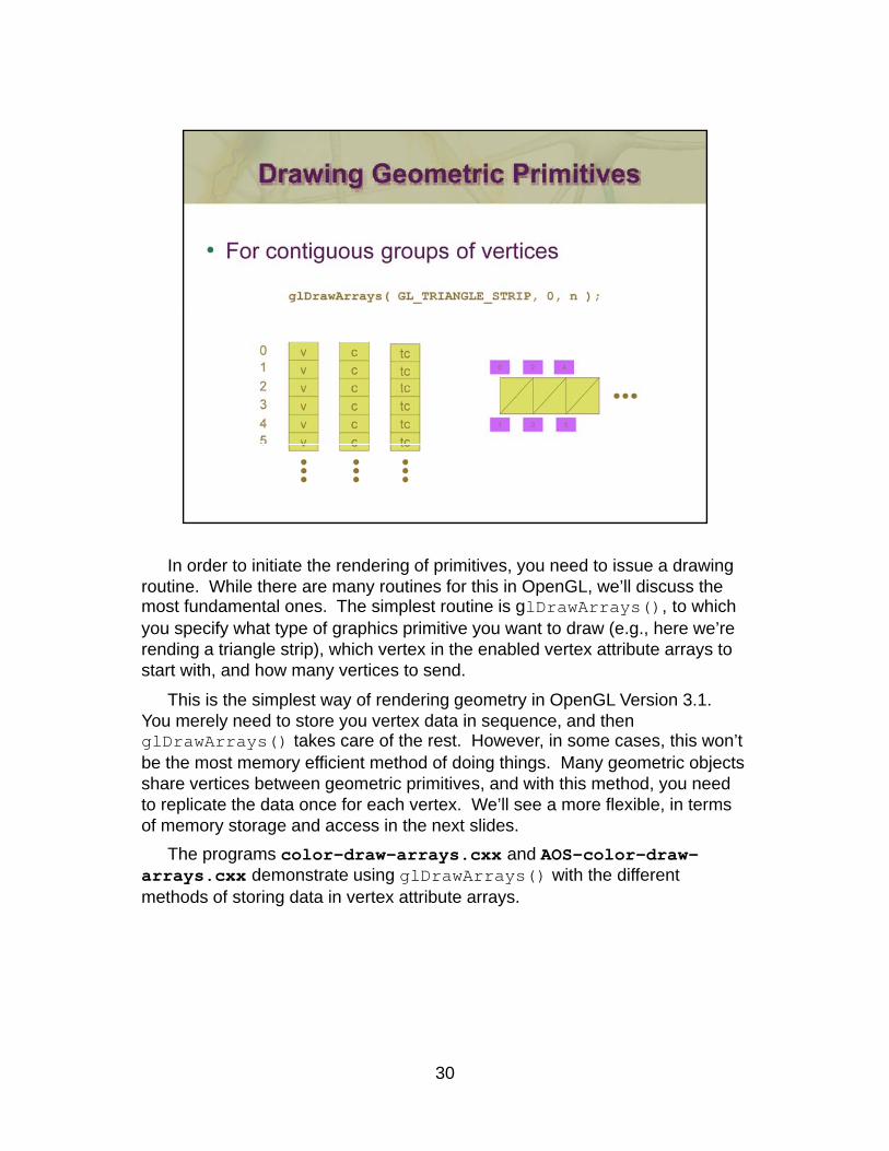
In order to initiate the rendering of primitives, you need to issue a drawing routine. While there are many routines for this in OpenGL, we’ll discuss the most fundamental ones. The simplest routine is glDrawArrays(), to which you specify what type of graphics primitive you want to draw (e.g., here we’re rending a triangle strip), which vertex in the enabled vertex attribute arrays to start with, and how many vertices to send.
This is the simplest way of rendering geometry in OpenGL Version 3.1. p y g g y pYou merely need to store you vertex data in sequence, and then glDrawArrays() takes care of the rest. However, in some cases, this won’t be the most memory efficient method of doing things. Many geometric objects share vertices between geometric primitives, and with this method, you need to replicate the data once for each vertex. We’ll see a more flexible, in terms of memory storage and access in the next slides.
The programs color-draw-arrays.cxx and AOS-color-draw-arrays.cxx demonstrate using glDrawArrays() with the different methods of storing data in vertex attribute arrays.
30
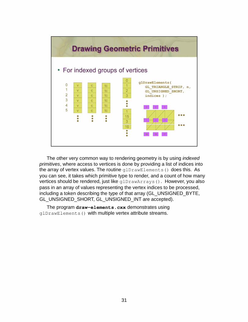
The other very common way to rendering geometry is by using indexed primitives, where access to vertices is done by providing a list of indices into the array of vertex values. The routine glDrawElements() does this. As you can see, it takes which primitive type to render, and a count of how many vertices should be rendered, just like glDrawArrays(). However, you also pass in an array of values representing the vertex indices to be processed, including a token describing the type of that array (GL_UNSIGNED_BYTE, GL UNSIGNED SHORT GL UNSIGNED INT t d)GL_UNSIGNED_SHORT, GL_UNSIGNED_INT are accepted).
The program draw-elements.cxx demonstrates using glDrawElements() with multiple vertex attribute streams.
31
32
- 33 -
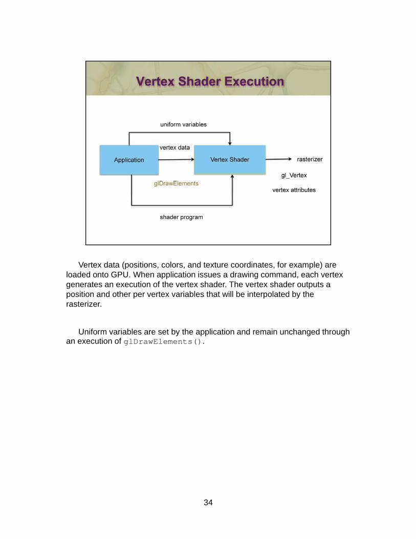
Vertex data (positions, colors, and texture coordinates, for example) are loaded onto GPU. When application issues a drawing command, each vertex generates an execution of the vertex shader. The vertex shader outputs a position and other per vertex variables that will be interpolated by the rasterizer.
Uniform variables are set by the application and remain unchanged throughUniform variables are set by the application and remain unchanged through an execution of glDrawElements().
34
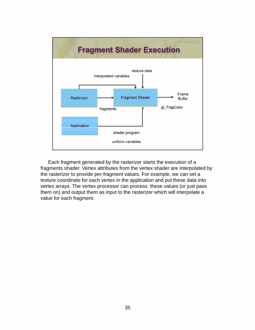
Each fragment generated by the rasterizer starts the execution of a fragments shader. Vertex attributes from the vertex shader are interpolated by the rasterizer to provide per-fragment values. For example, we can set a texture coordinate for each vertex in the application and put these data into vertex arrays. The vertex processor can process these values (or just pass them on) and output them as input to the rasterizer which will interpolate a value for each fragment.
35
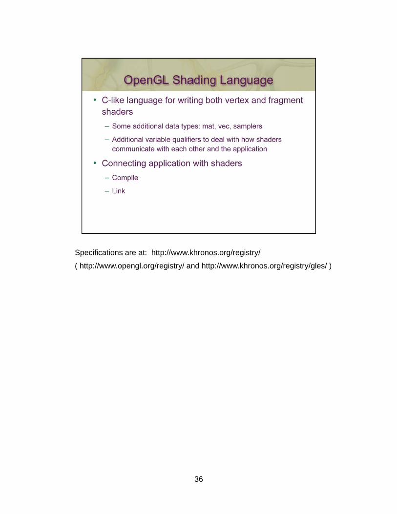
Specifications are at: http://www.khronos.org/registry/
( http://www.opengl.org/registry/ and http://www.khronos.org/registry/gles/ )
36

Here we some of the basic types and qualifiers used in GLSL. Since GLSL is very close to C (and C++ in some instances), we don’t dwell on the language constructs.
37
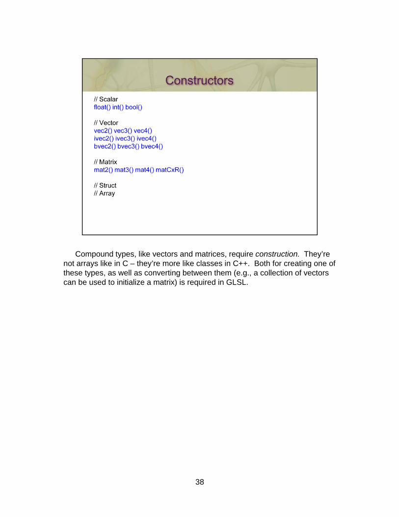
Compound types, like vectors and matrices, require construction. They’re not arrays like in C – they’re more like classes in C++. Both for creating one of these types, as well as converting between them (e.g., a collection of vectors can be used to initialize a matrix) is required in GLSL.
38
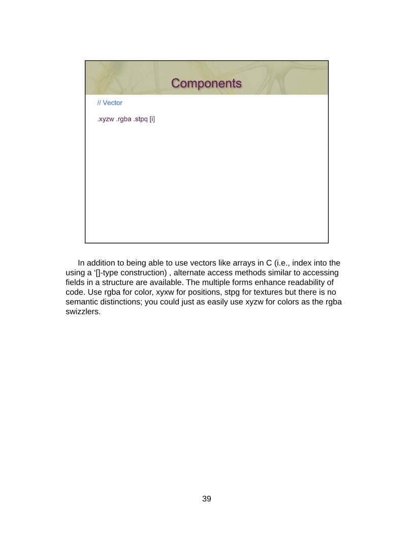
In addition to being able to use vectors like arrays in C (i.e., index into the using a ‘[]-type construction) , alternate access methods similar to accessing fields in a structure are available. The multiple forms enhance readability of code. Use rgba for color, xyxw for positions, stpg for textures but there is no semantic distinctions; you could just as easily use xyzw for colors as the rgba swizzlers.
39
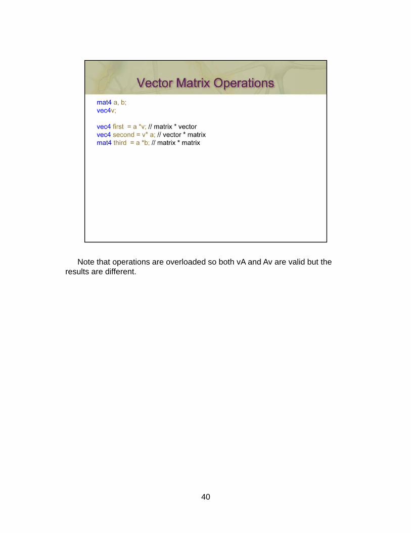
Note that operations are overloaded so both vA and Av are valid but the results are different.
40
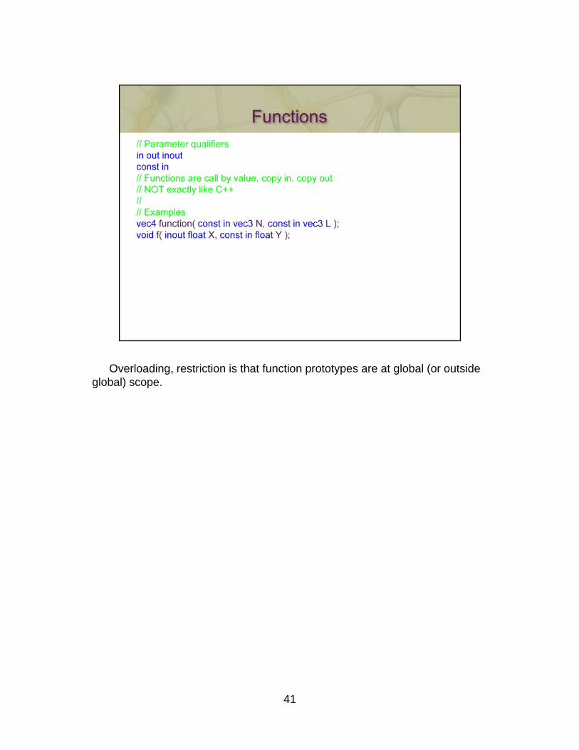
Overloading, restriction is that function prototypes are at global (or outside global) scope.
41
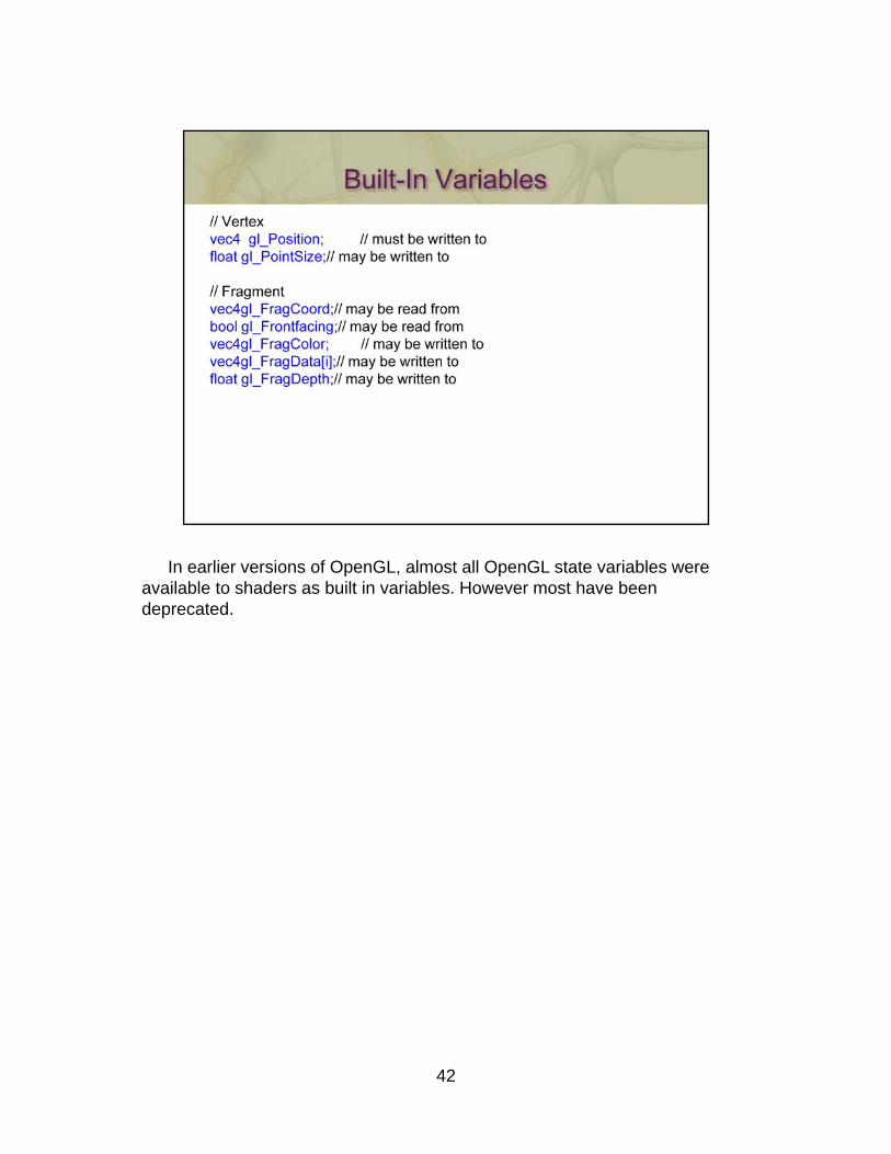
In earlier versions of OpenGL, almost all OpenGL state variables were available to shaders as built in variables. However most have been deprecated.
42
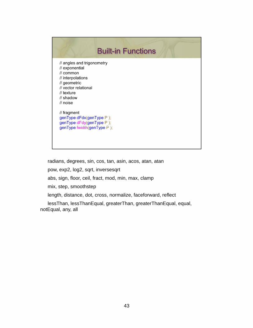
radians, degrees, sin, cos, tan, asin, acos, atan, atan
pow, exp2, log2, sqrt, inversesqrt
abs, sign, floor, ceil, fract, mod, min, max, clamp
mix, step, smoothstep
length, distance, dot, cross, normalize, faceforward, reflect
lessThan, lessThanEqual, greaterThan, greaterThanEqual, equal, notEqual, any, all
43
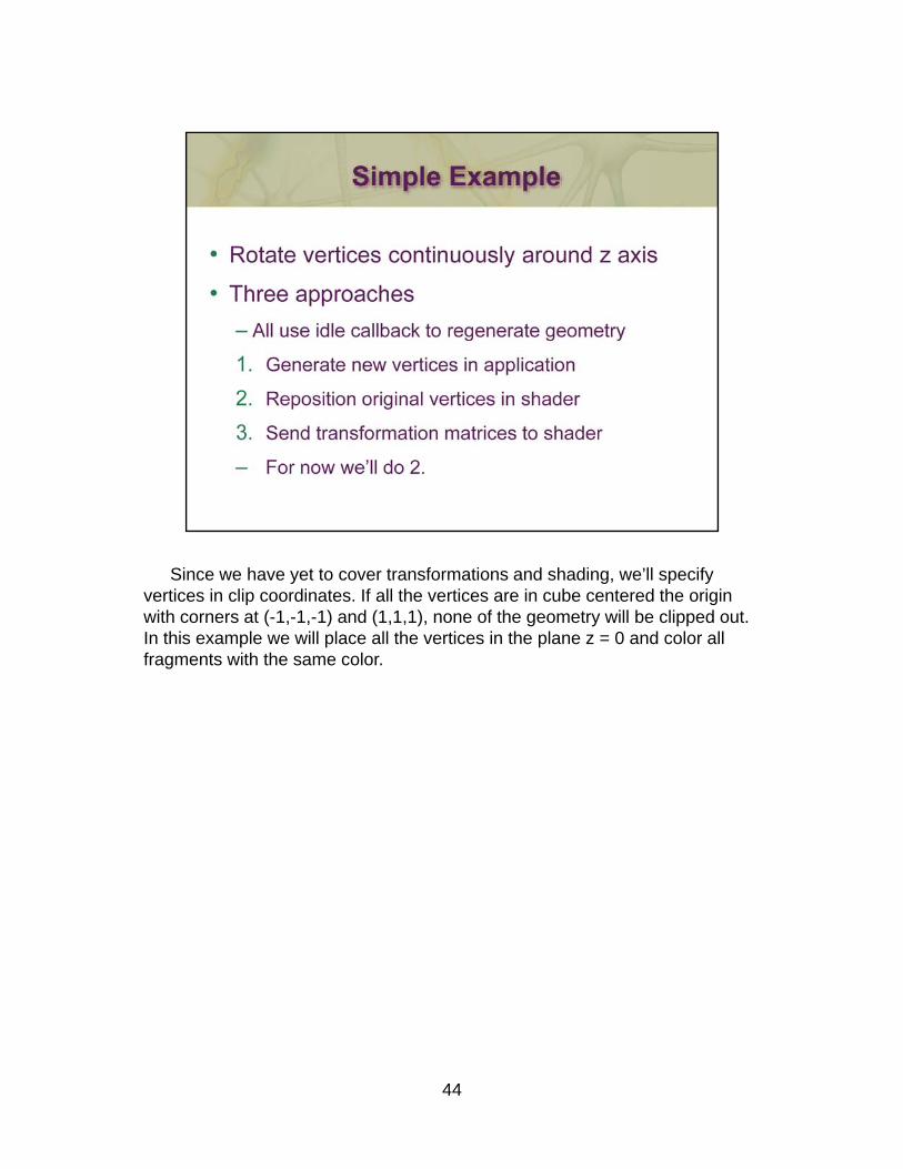
Since we have yet to cover transformations and shading, we’ll specify vertices in clip coordinates. If all the vertices are in cube centered the origin with corners at (-1,-1,-1) and (1,1,1), none of the geometry will be clipped out. In this example we will place all the vertices in the plane z = 0 and color all fragments with the same color.
44
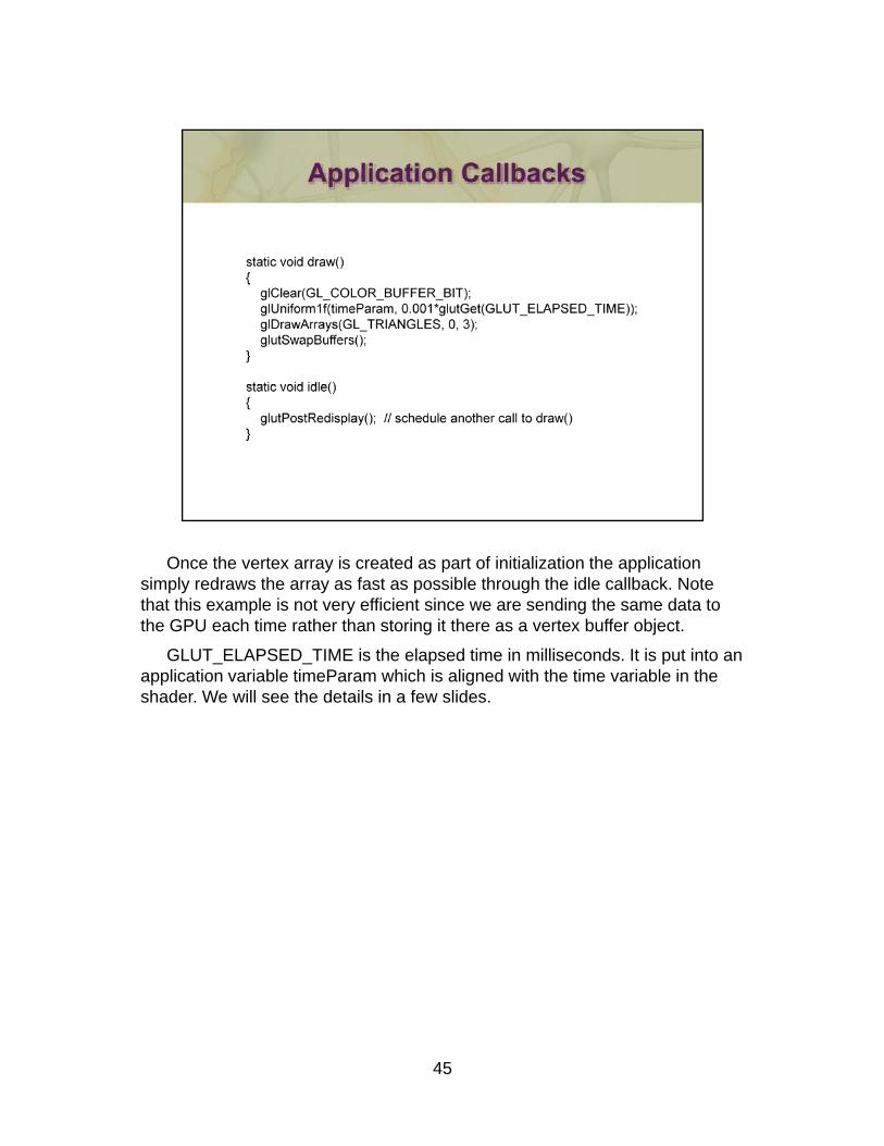
Once the vertex array is created as part of initialization the application simply redraws the array as fast as possible through the idle callback. Note that this example is not very efficient since we are sending the same data to the GPU each time rather than storing it there as a vertex buffer object.
GLUT_ELAPSED_TIME is the elapsed time in milliseconds. It is put into an application variable timeParam which is aligned with the time variable in the shader. We will see the details in a few slides.
45
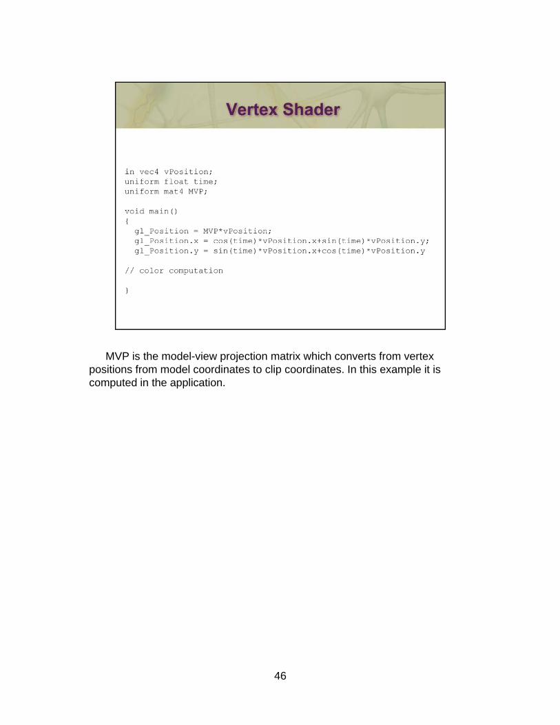
MVP is the model-view projection matrix which converts from vertex positions from model coordinates to clip coordinates. In this example it is computed in the application.
46
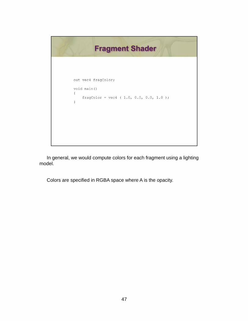
In general, we would compute colors for each fragment using a lighting model.
Colors are specified in RGBA space where A is the opacity.
47
48
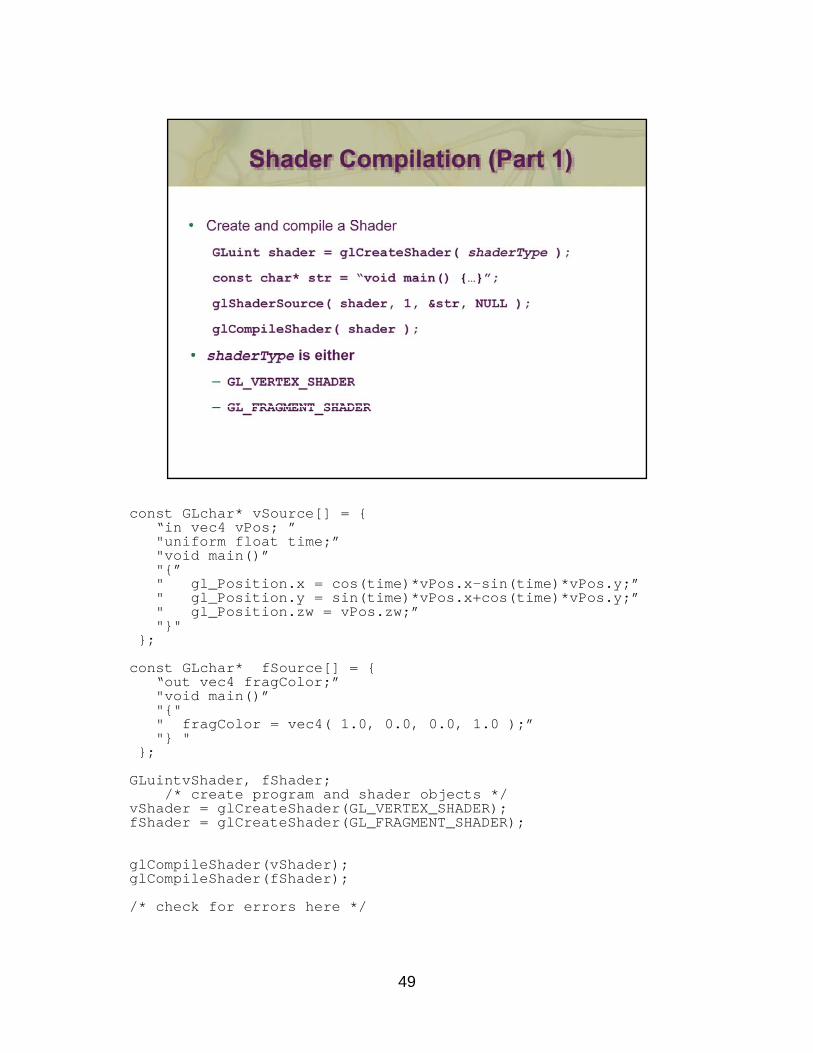
const GLchar* vSource[] = {“in vec4 vPos; ”in vec4 vPos; "uniform float time;”"void main()”"{”" gl_Position.x = cos(time)*vPos.x-sin(time)*vPos.y;”" gl_Position.y = sin(time)*vPos.x+cos(time)*vPos.y;”" gl_Position.zw = vPos.zw;”"}"
};
const GLchar* fSource[] = {“out vec4 fragColor;”"void main()”"{" " fragColor = vec4( 1.0, 0.0, 0.0, 1.0 );”"} "
};
GLuintvShader, fShader;/* create program and shader objects */
vShader = glCreateShader(GL_VERTEX_SHADER);fShader = glCreateShader(GL_FRAGMENT_SHADER);
glCompileShader(vShader); glCompileShader(fShader);
49
/* check for errors here */
50
51
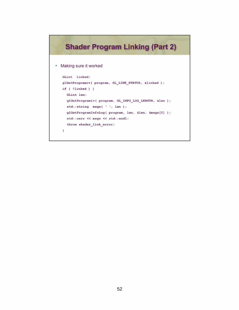
52
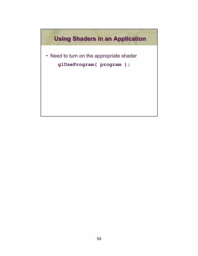
53
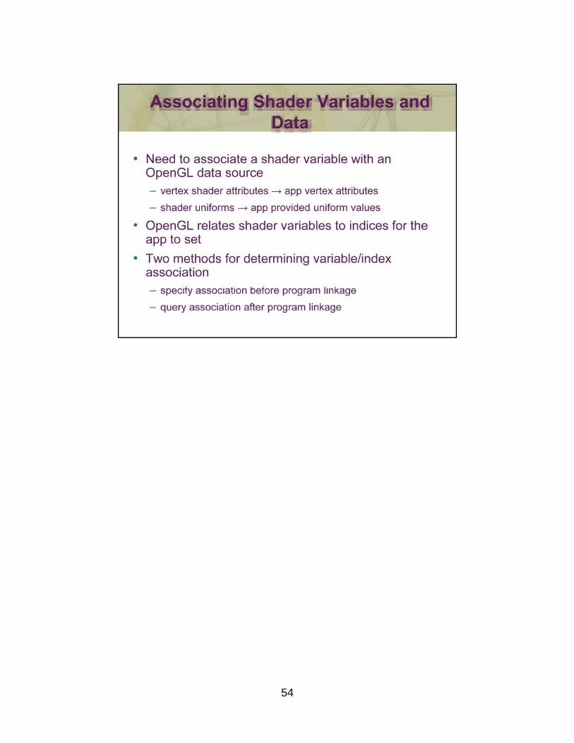
54
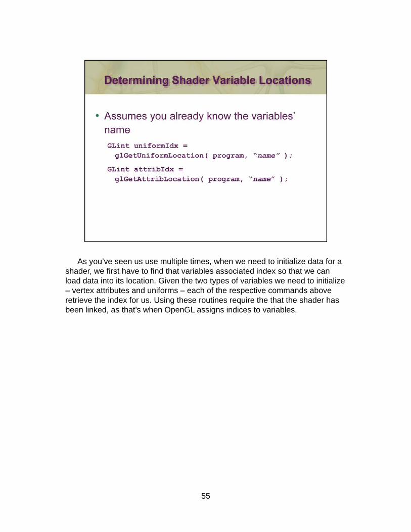
As you’ve seen us use multiple times, when we need to initialize data for a shader, we first have to find that variables associated index so that we can load data into its location. Given the two types of variables we need to initialize – vertex attributes and uniforms – each of the respective commands above retrieve the index for us. Using these routines require the that the shader has been linked, as that’s when OpenGL assigns indices to variables.
55
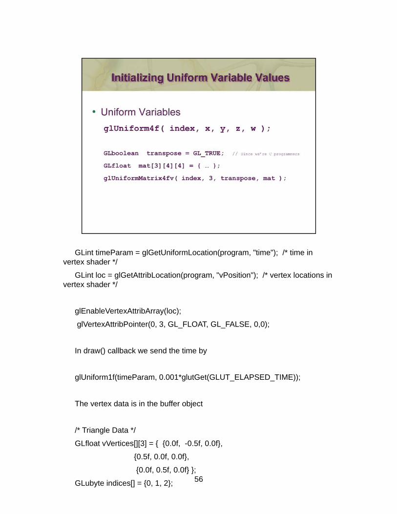
GLint timeParam = glGetUniformLocation(program, "time"); /* time in vertex shader */
GLint loc = glGetAttribLocation(program, "vPosition"); /* vertex locations in vertex shader */
glEnableVertexAttribArray(loc);
glVertexAttribPointer(0, 3, GL_FLOAT, GL_FALSE, 0,0);
In draw() callback we send the time by
glUniform1f(timeParam, 0.001*glutGet(GLUT_ELAPSED_TIME));
The vertex data is in the buffer object
/* Triangle Data */
56
/ Triangle Data /
GLfloat vVertices[][3] = { {0.0f, -0.5f, 0.0f},
{0.5f, 0.0f, 0.0f},
{0.0f, 0.5f, 0.0f} };
GLubyte indices[] = {0, 1, 2};

- 57 -
Transformations are fundamental to computer graphics, and OpenGL leverages them quite heavily. The most common use is for manipulating the position and orientation of 3D objects, but they also find applications in modifying colors, and other vector quantities used in graphics. For OpenGL, transformations are represented by 4 × 4 matrices. These matrices are applied in shaders, and can either be static (e.g., “hard coded” in a shader’s source code), or loaded dynamically by the application into a shader variable.
- 58 -
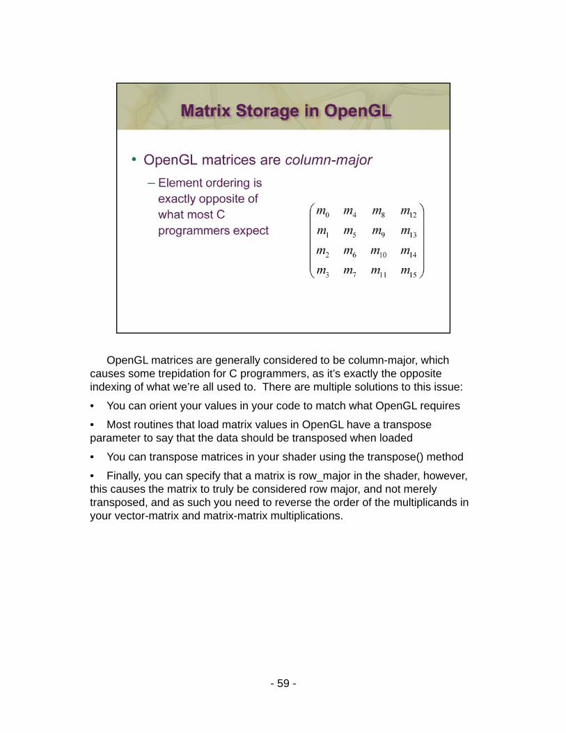
OpenGL matrices are generally considered to be column-major, which causes some trepidation for C programmers, as it’s exactly the opposite indexing of what we’re all used to. There are multiple solutions to this issue:
• You can orient your values in your code to match what OpenGL requires
• Most routines that load matrix values in OpenGL have a transpose parameter to say that the data should be transposed when loaded
• You can transpose matrices in your shader using the transpose() method
• Finally, you can specify that a matrix is row_major in the shader, however, this causes the matrix to truly be considered row major, and not merely transposed, and as such you need to reverse the order of the multiplicands in your vector-matrix and matrix-matrix multiplications.
- 59 -
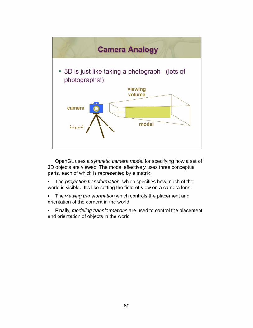
OpenGL uses a synthetic camera model for specifying how a set of 3D objects are viewed. The model effectively uses three conceptual parts, each of which is represented by a matrix:
• The projection transformation which specifies how much of the world is visible. It’s like setting the field-of-view on a camera lens
• The viewing transformation which controls the placement and orientation of the camera in the worldorientation of the camera in the world
• Finally, modeling transformations are used to control the placement and orientation of objects in the world
60
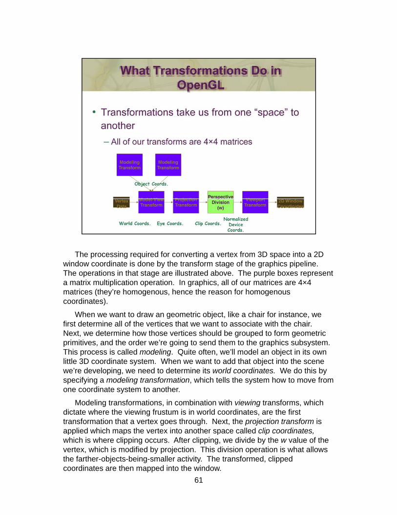
The processing required for converting a vertex from 3D space into a 2D p g q g pwindow coordinate is done by the transform stage of the graphics pipeline. The operations in that stage are illustrated above. The purple boxes represent a matrix multiplication operation. In graphics, all of our matrices are 4×4 matrices (they’re homogenous, hence the reason for homogenous coordinates).
When we want to draw an geometric object like a chair for instance weWhen we want to draw an geometric object, like a chair for instance, we first determine all of the vertices that we want to associate with the chair. Next, we determine how those vertices should be grouped to form geometric primitives, and the order we’re going to send them to the graphics subsystem. This process is called modeling. Quite often, we’ll model an object in its own little 3D coordinate system. When we want to add that object into the scene we’re developing, we need to determine its world coordinates. We do this by p g yspecifying a modeling transformation, which tells the system how to move from one coordinate system to another.
Modeling transformations, in combination with viewing transforms, which dictate where the viewing frustum is in world coordinates, are the first transformation that a vertex goes through. Next, the projection transform is applied which maps the vertex into another space called clip coordinates,
61
applied which maps the vertex into another space called clip coordinates,which is where clipping occurs. After clipping, we divide by the w value of the vertex, which is modified by projection. This division operation is what allows the farther-objects-being-smaller activity. The transformed, clipped coordinates are then mapped into the window.

Another essential part of the graphics processing is setting up how much ofAnother essential part of the graphics processing is setting up how much of the world we can see. We construct a viewing frustum, which defines the chunk of 3-space that we can see. There are two types of views: a perspective view, which you’re familiar with as it’s how your eye works, is used to generate frames that match your view of reality–things farther from your appear smaller. This is the type of view used for video games, simulations, and most graphics applications in general.
The other view, orthographic, is used principally for engineering and design situations, where relative lengths and angles need to be preserved.
For a perspective, we locate the eye at the apex of the frustum pyramid. We can see any objects which are between the two planes perpendicular to eye (they’re called the near and far clipping planes, respectively). Any vertices between near and far, and inside the four planes that connect them will be rendered Otherwise those vertices are clipped out and discarded In somerendered. Otherwise, those vertices are clipped out and discarded. In some cases a primitive will be entirely outside of the view, and the system will discard it for that frame. Other primitives might intersect the frustum, which we clip such that the part of them that’s outside is discarded and we create new vertices for the modified primitive.
While the system can easily determine which primitive are inside the frustum, it’s wasteful of system bandwidth to have lots of primitives discarded
62
in this manner. We utilize a technique named culling to determine exactly which primitives need to be sent to the graphics processor, and send only those primitives to maximize its efficiency.
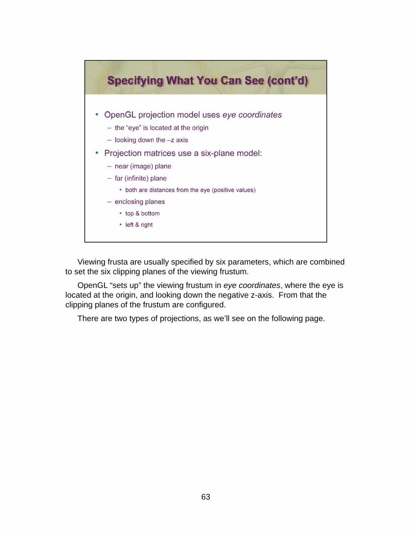
Viewing frusta are usually specified by six parameters, which are combined to set the six clipping planes of the viewing frustum.
OpenGL “sets up” the viewing frustum in eye coordinates, where the eye is located at the origin, and looking down the negative z-axis. From that the clipping planes of the frustum are configured.
There are two types of projections, as we’ll see on the following page.
63
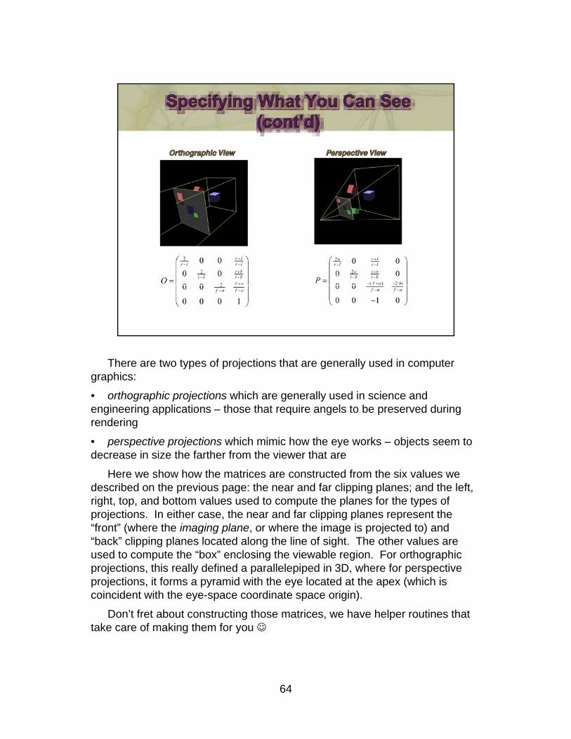
There are two types of projections that are generally used in computer graphics:
• orthographic projections which are generally used in science and engineering applications – those that require angels to be preserved during rendering
• perspective projections which mimic how the eye works – objects seem to decrease in size the farther from the viewer that aredecrease in size the farther from the viewer that are
Here we show how the matrices are constructed from the six values we described on the previous page: the near and far clipping planes; and the left, right, top, and bottom values used to compute the planes for the types of projections. In either case, the near and far clipping planes represent the “front” (where the imaging plane, or where the image is projected to) and “b k” li i l l t d l th li f i ht Th th l“back” clipping planes located along the line of sight. The other values are used to compute the “box” enclosing the viewable region. For orthographic projections, this really defined a parallelepiped in 3D, where for perspective projections, it forms a pyramid with the eye located at the apex (which is coincident with the eye-space coordinate space origin).
Don’t fret about constructing those matrices, we have helper routines that
64
take care of making them for you ☺
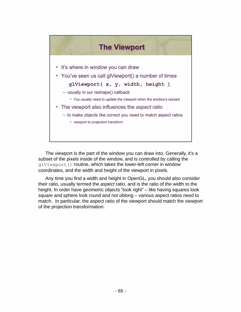
The viewport is the part of the window you can draw into. Generally, it’s a subset of the pixels inside of the window, and is controlled by calling the glViewport() routine, which takes the lower-left corner in window coordinates, and the width and height of the viewport in pixels.
Any time you find a width and height in OpenGL, you should also consider their ratio, usually termed the aspect ratio, and is the ratio of the width to the height. In order have geometric objects “look right” – like having squares look g g j g g qsquare and sphere look round and not oblong – various aspect ratios need to match. In particular, the aspect ratio of the viewport should match the viewport of the projection transformation.
- 65 -
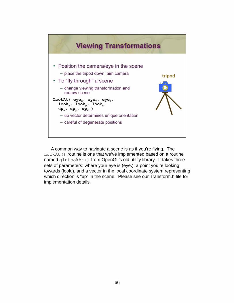
A common way to navigate a scene is as if you’re flying. The LookAt() routine is one that we’ve implemented based on a routine named gluLookAt() from OpenGL’s old utility library. It takes three sets of parameters: where your eye is (eye*); a point you’re looking towards (look*), and a vector in the local coordinate system representing which direction is “up” in the scene. Please see our Transform.h file for implementation details.
66
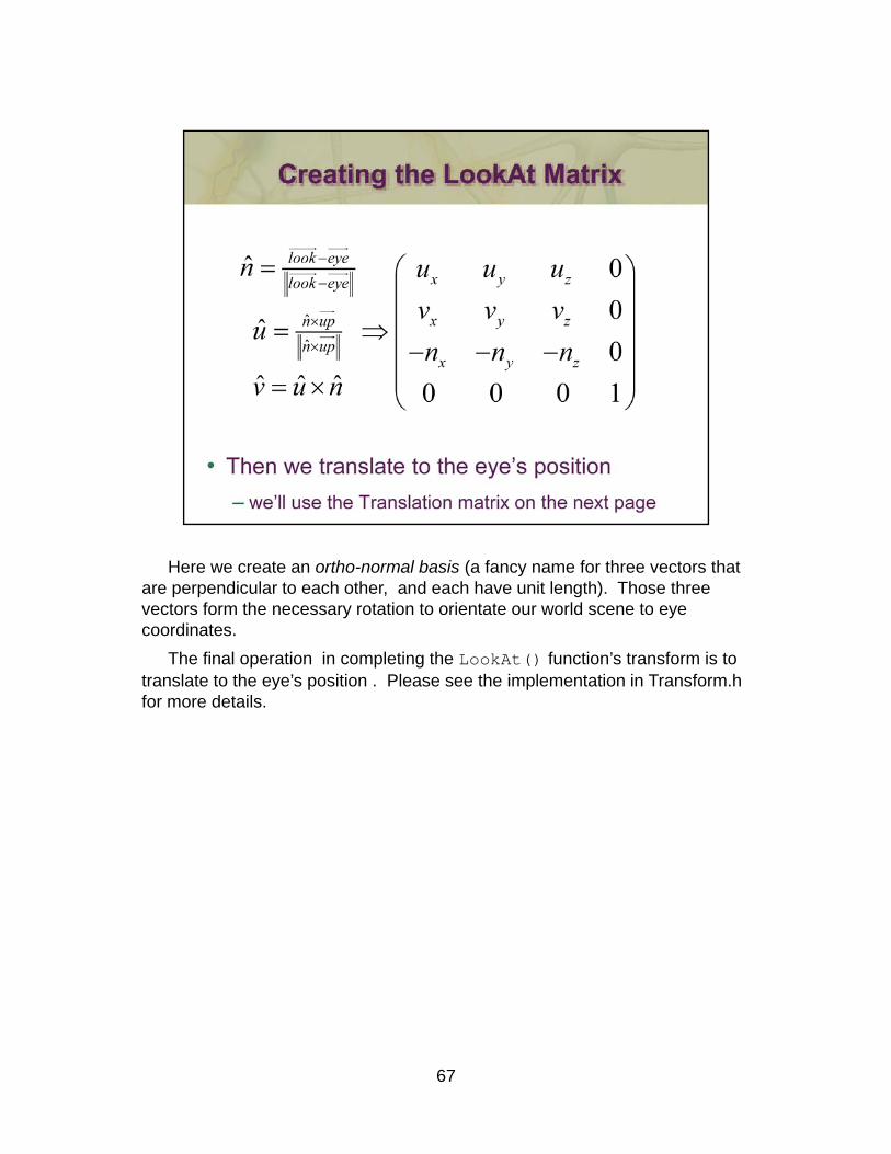
Here we create an ortho-normal basis (a fancy name for three vectors that are perpendicular to each other, and each have unit length). Those three vectors form the necessary rotation to orientate our world scene to eye coordinates.
The final operation in completing the LookAt() function’s transform is to translate to the eye’s position . Please see the implementation in Transform.h for more details.
67
68
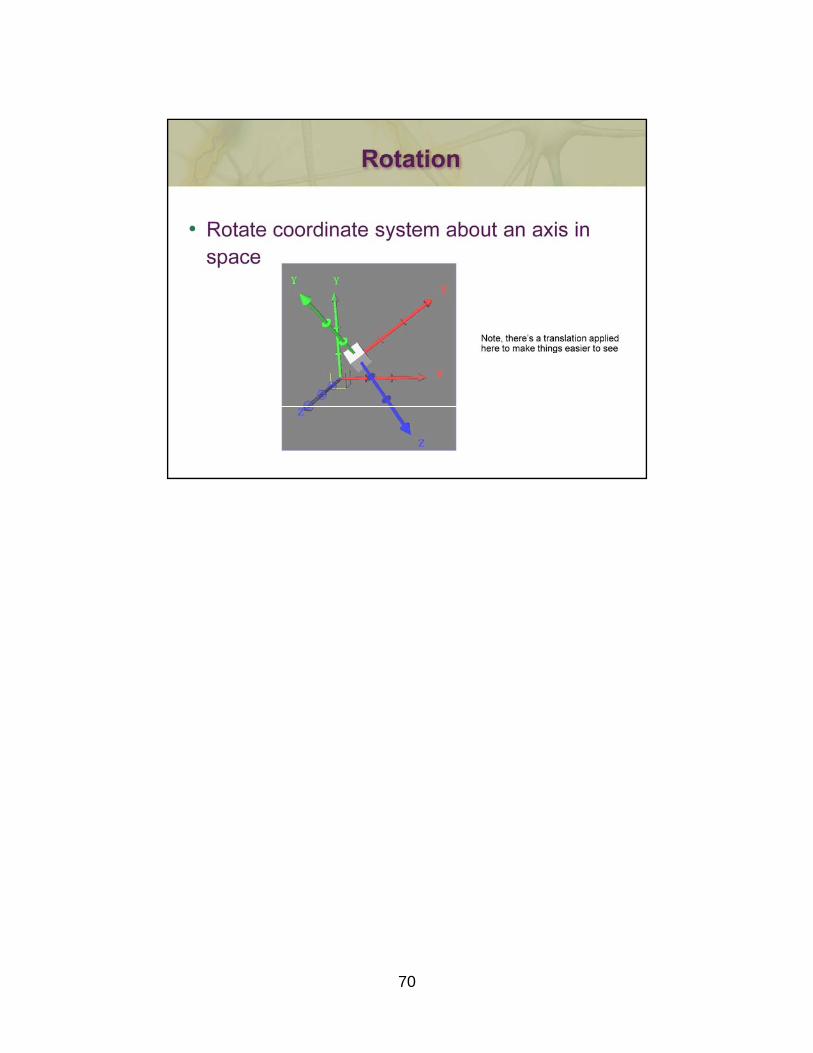
69
70
71

We know all that matrix math could be intimidating if you’re not too familiar with linear algebra. We’ve written a header file, Transform.h, that takes implements all of those routines, manages the row and column ordering of the matrices, and makes it very easy to integrate them with your shaders.
For example, you might want to use a perspective projection matrix in shader. Here’s how you’d do that with our code (this assumes your shader has a variable named “P” for the projection matrix):p j )
projIndex = glGetUniformLocation( program, “P” );
Matrix p = Perspective( 120.0, aspectRatio, zNear, zFar );
glUniformMatrix4fv( projIndex, 1, /* transpose matrix? */ GL_FALSE, p );
- 72 -
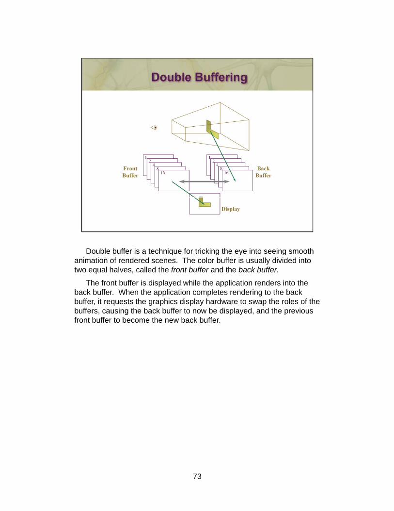
Double buffer is a technique for tricking the eye into seeing smooth animation of rendered scenes. The color buffer is usually divided into two equal halves, called the front buffer and the back buffer.
The front buffer is displayed while the application renders into the back buffer. When the application completes rendering to the back buffer, it requests the graphics display hardware to swap the roles of the buffers, causing the back buffer to now be displayed, and the previous , g p y , pfront buffer to become the new back buffer.
73
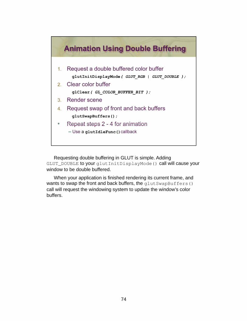
Requesting double buffering in GLUT is simple. Adding GLUT_DOUBLE to your glutInitDisplayMode() call will cause your window to be double buffered.
When your application is finished rendering its current frame, and wants to swap the front and back buffers, the glutSwapBuffers()call will request the windowing system to update the window’s color buffers.
74
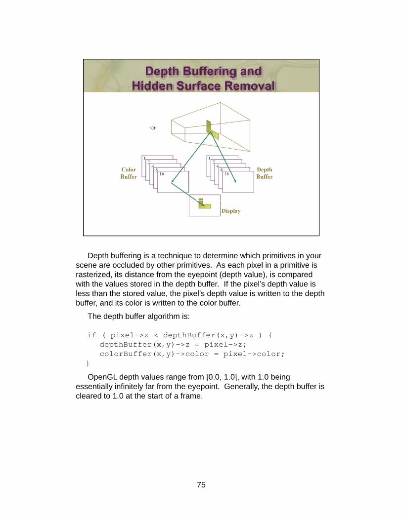
Depth buffering is a technique to determine which primitives in your scene are occluded by other primitives. As each pixel in a primitive is rasterized, its distance from the eyepoint (depth value), is compared with the values stored in the depth buffer. If the pixel’s depth value is less than the stored value, the pixel’s depth value is written to the depth buffer, and its color is written to the color buffer.
The depth buffer algorithm is:p g
if ( pixel->z < depthBuffer(x,y)->z ) {depthBuffer(x,y)->z = pixel->z;colorBuffer(x,y)->color = pixel->color;
}
OpenGL depth values range from [0 0 1 0] with 1 0 beingOpenGL depth values range from [0.0, 1.0], with 1.0 being essentially infinitely far from the eyepoint. Generally, the depth buffer is cleared to 1.0 at the start of a frame.
75
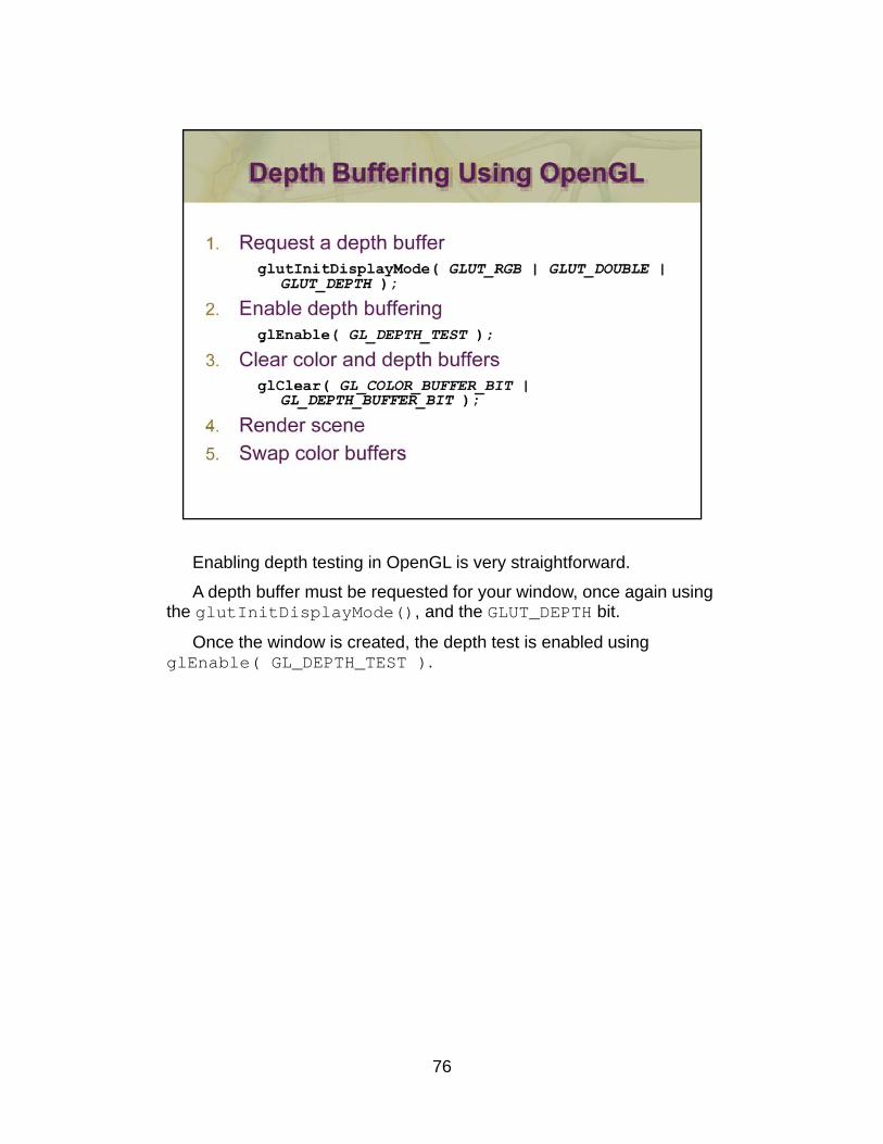
Enabling depth testing in OpenGL is very straightforward.
A depth buffer must be requested for your window, once again using the glutInitDisplayMode(), and the GLUT_DEPTH bit.
Once the window is created, the depth test is enabled usingglEnable( GL_DEPTH_TEST ).
76
- 77 -
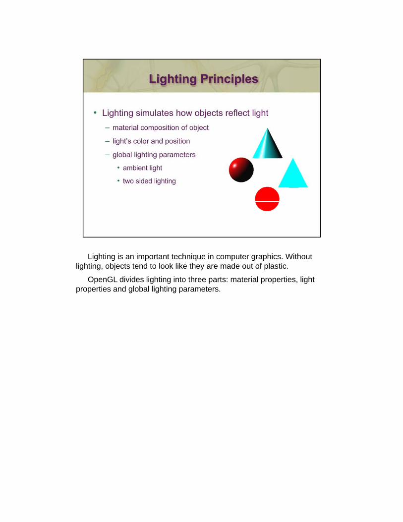
Lighting is an important technique in computer graphics. Without lighting, objects tend to look like they are made out of plastic.
OpenGL divides lighting into three parts: material properties, light properties and global lighting parameters.
OpenGL can use the shade at one vertex to shade an entire polygon (constant shading) or interpolated the shades at the vertices across the polygon (smooth shading), the default.
The orientation of a surface is specified by the normal at each point. For a flat polygon the normal is constant over the polygon. Because normals are specified by the application program and can be changed between the specification of vertices, when we shade a polygon it can appear to be curved.
Classically, OpenGL lighting was based on the Phong lighting model. At each vertex in the primitive, a color is computed using that primitives material properties along with the light settings.
The color for the vertex is computed by adding four computed colors for the final vertex color. The four contributors to the vertex color are:
•Ambient is color of the object from all the undirected light in a scene.•Diffuse is the base color of the object under current lighting. There must be a light shining on the object to get a diffuse contribution.•Specular is the contribution of the shiny highlights on the object.•Emission is the contribution added in if the object emits light•Emission is the contribution added in if the object emits light (i.e., glows)
Since we need to do this in shaders, we’ll discuss this model as it provides a nice description, but please realize there are more accurate lighting models available you could implement in your shaders.
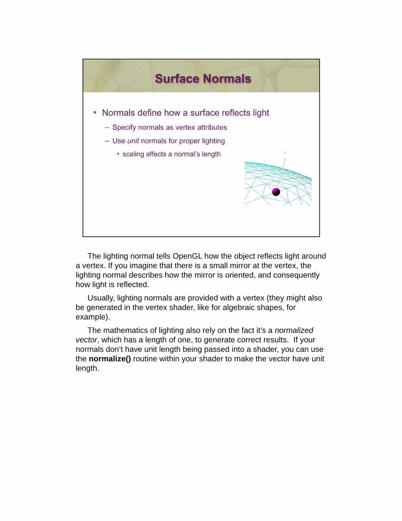
The lighting normal tells OpenGL how the object reflects light around a vertex. If you imagine that there is a small mirror at the vertex, the lighting normal describes how the mirror is oriented, and consequently how light is reflected.
Usually, lighting normals are provided with a vertex (they might also be generated in the vertex shader, like for algebraic shapes, for example).p )
The mathematics of lighting also rely on the fact it’s a normalizedvector, which has a length of one, to generate correct results. If your normals don’t have unit length being passed into a shader, you can use the normalize() routine within your shader to make the vector have unit length.
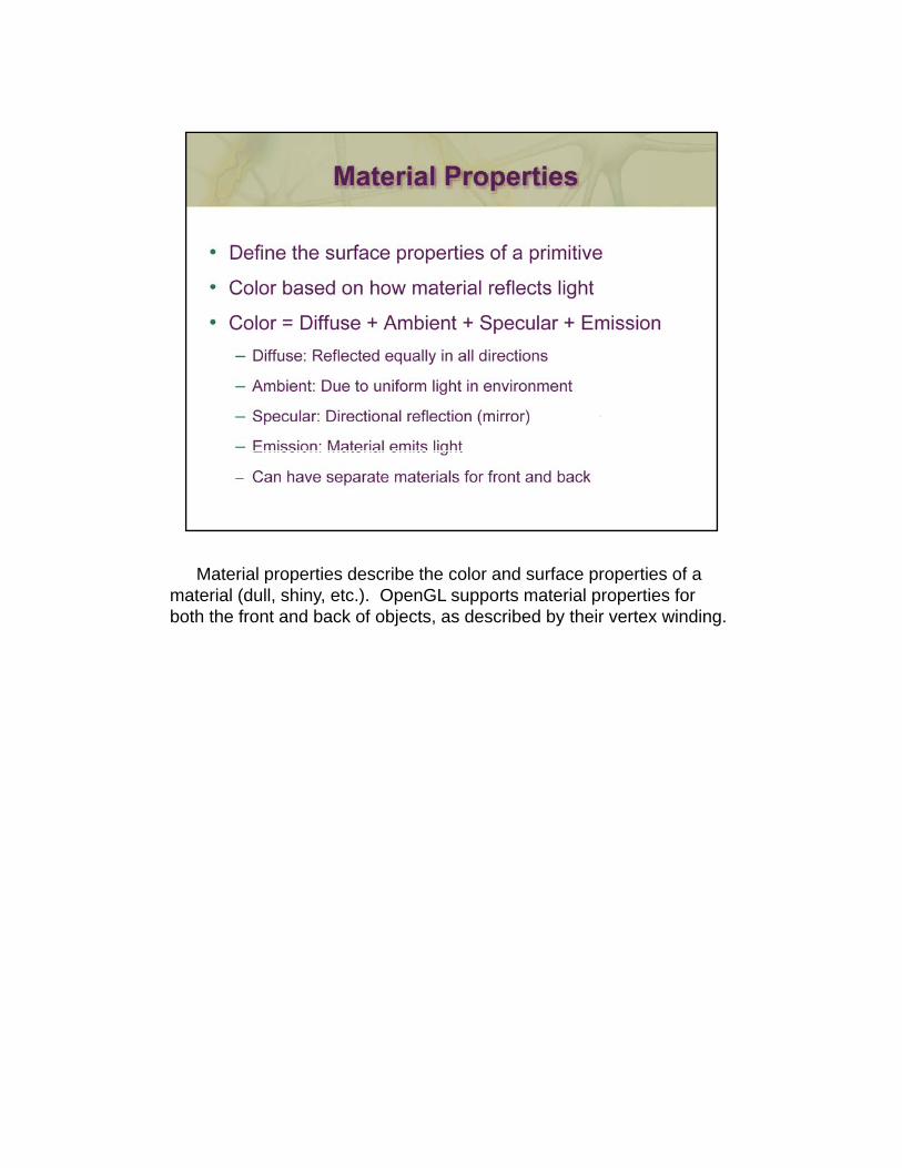
Material properties describe the color and surface properties of a material (dull, shiny, etc.). OpenGL supports material properties for both the front and back of objects, as described by their vertex winding.
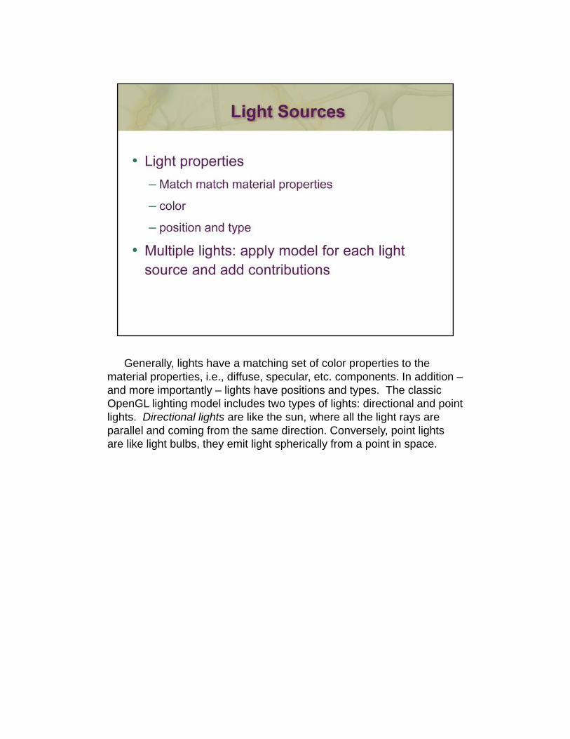
Generally, lights have a matching set of color properties to the material properties, i.e., diffuse, specular, etc. components. In addition –and more importantly – lights have positions and types. The classic OpenGL lighting model includes two types of lights: directional and point lights. Directional lights are like the sun, where all the light rays are parallel and coming from the same direction. Conversely, point lights are like light bulbs, they emit light spherically from a point in space.
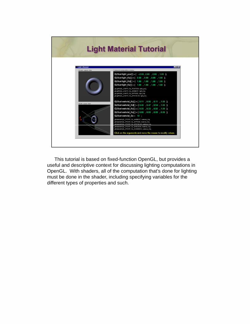
This tutorial is based on fixed-function OpenGL, but provides a useful and descriptive context for discussing lighting computations in OpenGL. With shaders, all of the computation that’s done for lighting must be done in the shader, including specifying variables for the different types of properties and such.
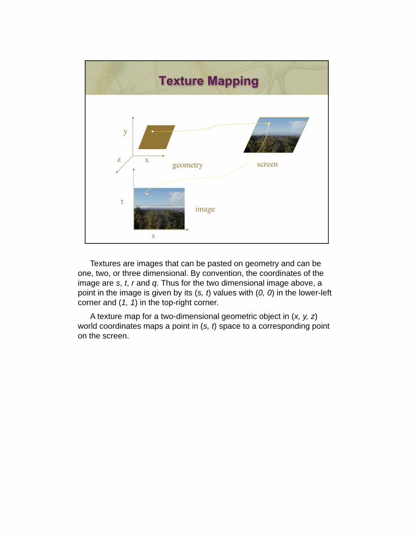
Textures are images that can be pasted on geometry and can be one, two, or three dimensional. By convention, the coordinates of the image are s, t, r and q. Thus for the two dimensional image above, a point in the image is given by its (s, t) values with (0, 0) in the lower-left corner and (1, 1) in the top-right corner.
A texture map for a two-dimensional geometric object in (x, y, z) world coordinates maps a point in (s, t) space to a corresponding point p p ( , ) p p g pon the screen.
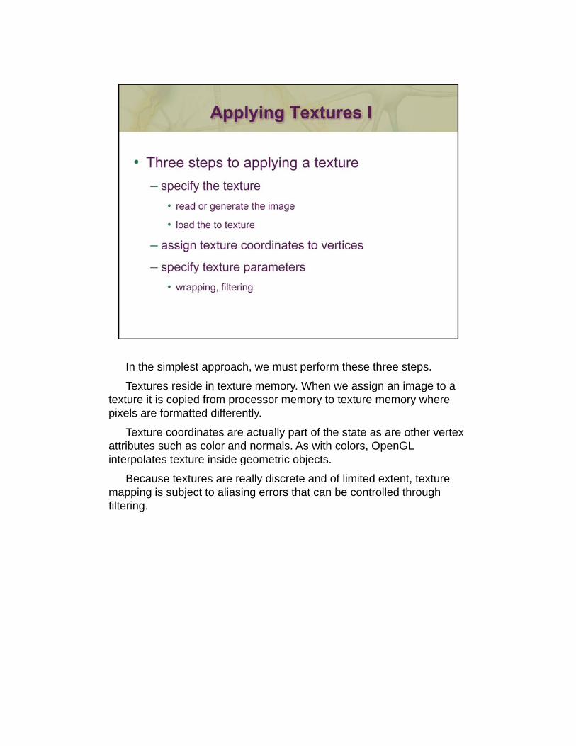
In the simplest approach, we must perform these three steps.
Textures reside in texture memory. When we assign an image to a texture it is copied from processor memory to texture memory where pixels are formatted differently.
Texture coordinates are actually part of the state as are other vertex attributes such as color and normals. As with colors, OpenGL interpolates texture inside geometric objectsinterpolates texture inside geometric objects.
Because textures are really discrete and of limited extent, texture mapping is subject to aliasing errors that can be controlled through filtering.
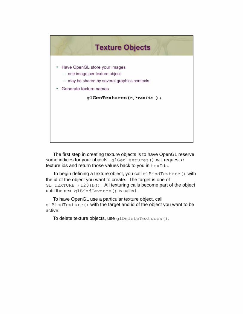
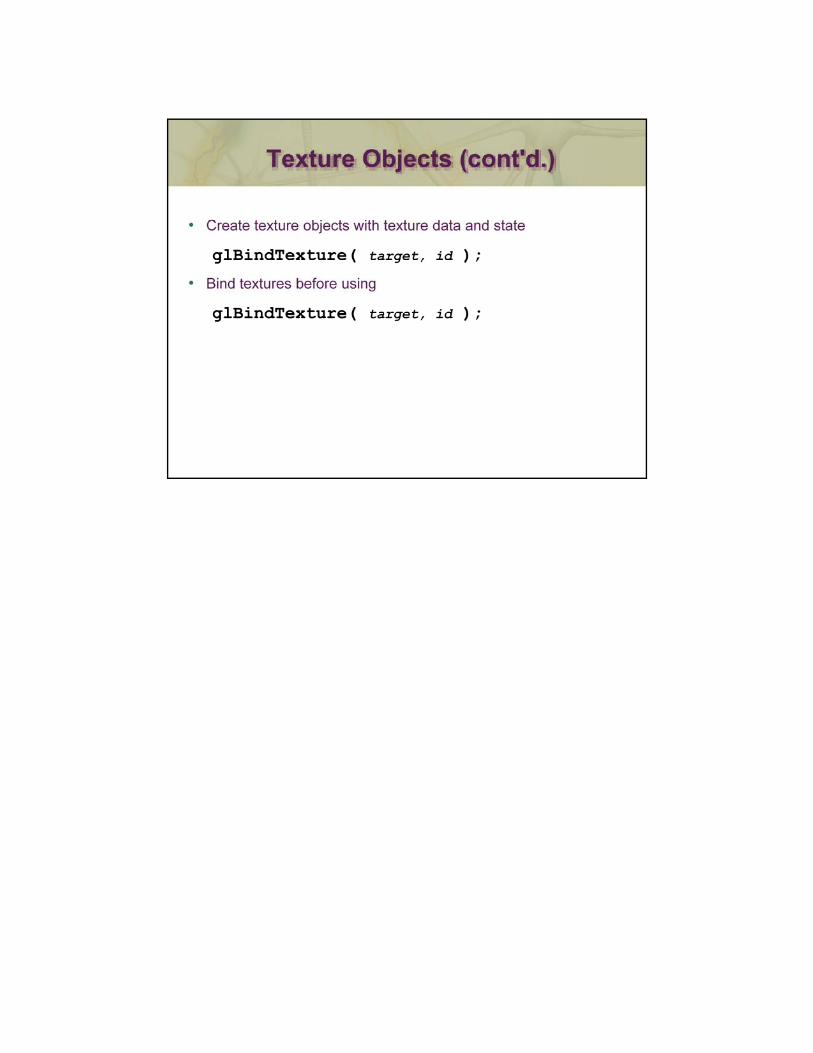
The first step in creating texture objects is to have OpenGL reserve some indices for your objects. glGenTextures() will request ntexture ids and return those values back to you in texIds.
To begin defining a texture object, you call glBindTexture() with the id of the object you want to create. The target is one of GL_TEXTURE_{123}D(). All texturing calls become part of the object until the next glBindTexture() is called.g ()
To have OpenGL use a particular texture object, call glBindTexture() with the target and id of the object you want to be active.
To delete texture objects, use glDeleteTextures().
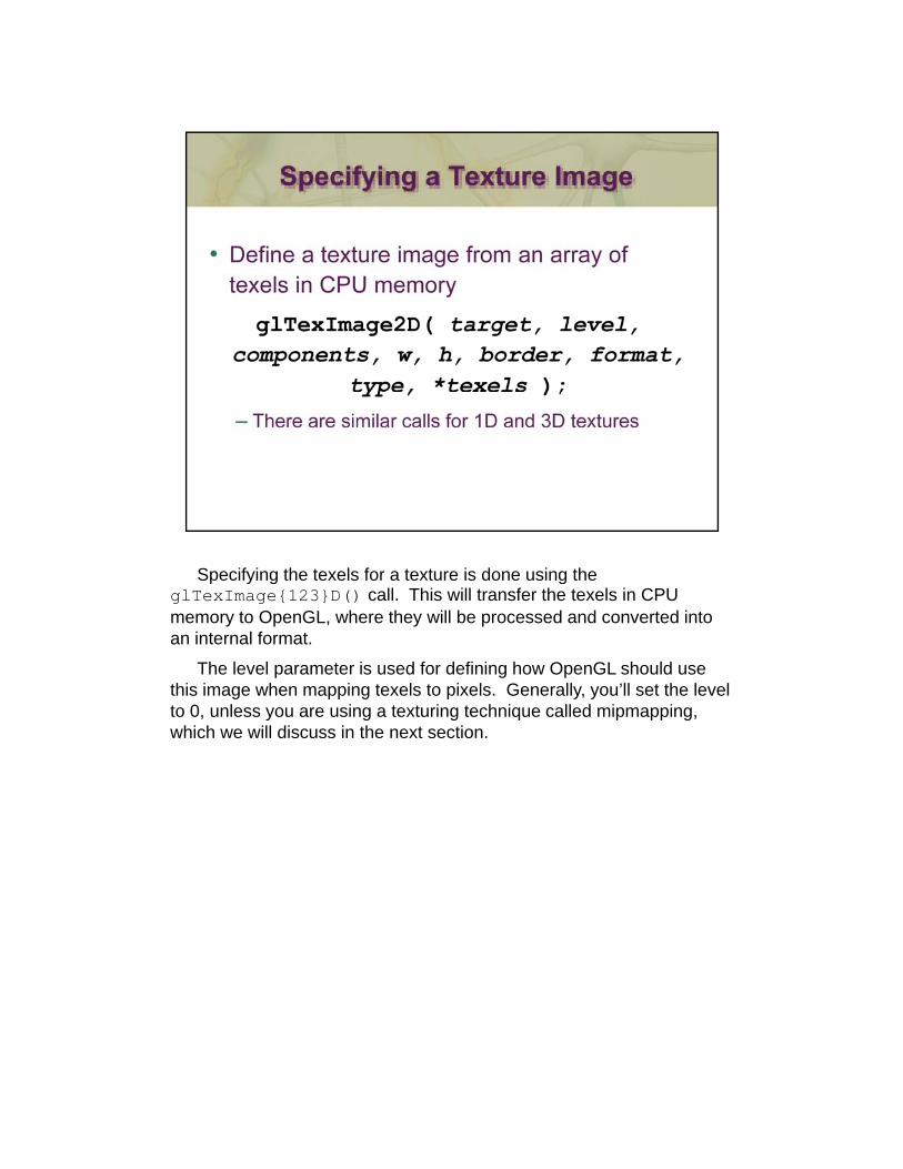
Specifying the texels for a texture is done using the glTexImage{123}D() call. This will transfer the texels in CPU memory to OpenGL, where they will be processed and converted into an internal format.
The level parameter is used for defining how OpenGL should use this image when mapping texels to pixels. Generally, you’ll set the level to 0, unless you are using a texturing technique called mipmapping, , y g g q p pp g,which we will discuss in the next section.
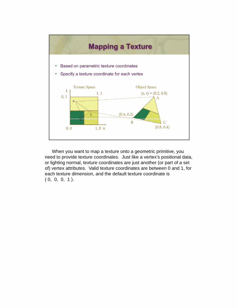
When you want to map a texture onto a geometric primitive, you need to provide texture coordinates. Just like a vertex’s positional data, or lighting normal, texture coordinates are just another (or part of a set of) vertex attributes. Valid texture coordinates are between 0 and 1, for each texture dimension, and the default texture coordinate is ( 0, 0, 0, 1 ).
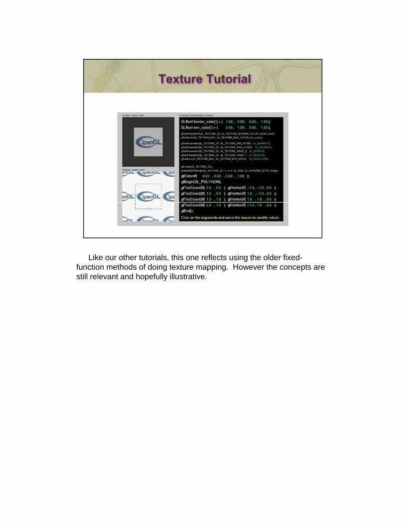
Like our other tutorials, this one reflects using the older fixed-function methods of doing texture mapping. However the concepts are still relevant and hopefully illustrative.
During rendering, you can sample multiple textures and apply them to a single geometric object. This is a handy technique as often, you’ll have a texture map for the surfaces appearance, another one for controlling the surfaces roughness (these are commonly called gloss maps – think of being a map of where a surface has shown wear or is still shiny and reflective), still more for light maps, or transparency maps.
Each texture map needs to be associated with its own texture unit, which is capable of storing a single (perhaps mipmapped) texture. To switch between different texture units, call glActiveTexture() passing the token GL_TEXTUREn, where n runs form zero to one less than the number of supported texture units.
Inside of your shader, you’ll access a particular texture unit using a sampler. Samplers are uniform variables, whose type must match the type of texture bound to that texture unit. The available types of texture samplers are: sampler1D, sampler2D, sampler3D, samplerCube(and a few more advanced versions). When you load a texture, the call and type of texture (e.g., calling glTexture2D() with GL_TEXTURE_2D) specifies which type of sampler is capable of accessing that texture. In this case, you’d use a sampler2D to access the texture. The final issue is that you need to associate the texture unit’s number (the n you specified when calling glActiveTexture()) with the sampler. Being a uniform, you do that by loading a uniform variable with the texture unit’s number. For example, in the shader, say we declare “uniform sampler2D tex;”. If we’ve loaded a two-dimensional texture into texture unit four, we’d need to do the following:
GLuint texLoc = glGetUniformLocation( program, “tex” );
glUniform1i( texLoc, 4 );glUniform1i( texLoc, 4 );
After doing that, we can access the texture from our shader.
- 94 -
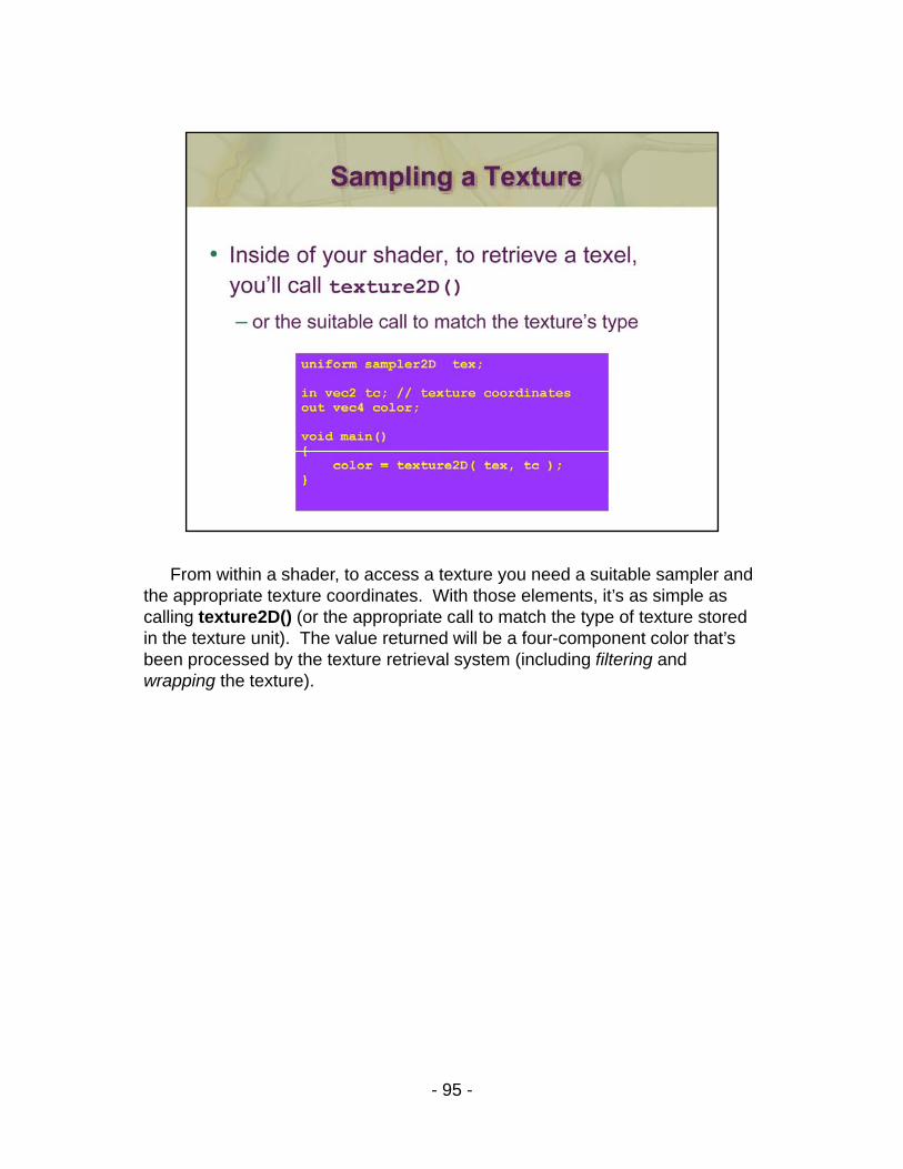
From within a shader, to access a texture you need a suitable sampler and the appropriate texture coordinates. With those elements, it’s as simple as calling texture2D() (or the appropriate call to match the type of texture stored in the texture unit). The value returned will be a four-component color that’s been processed by the texture retrieval system (including filtering and wrapping the texture).
- 95 -
Textures and the objects being textured are rarely the same size ( in pixels ). Filter modes determine the methods used by how texels should be expanded ( magnification ), or shrunk ( minification ) to match a pixel’s size. An additional technique, called mipmapping is a special instance of a minification filter.
Wrap modes determine how to process texture coordinates outside p pof the [0,1] range. The available modes are:
GL_CLAMP - clamp any values outside the range to closest valid value,
causing the edges of the texture to be “smeared” across the primitive
l th f ti l t f th t t di tGL_REPEAT - use only the fractional part of the texture coordinate, causing the texture to repeat across an object.
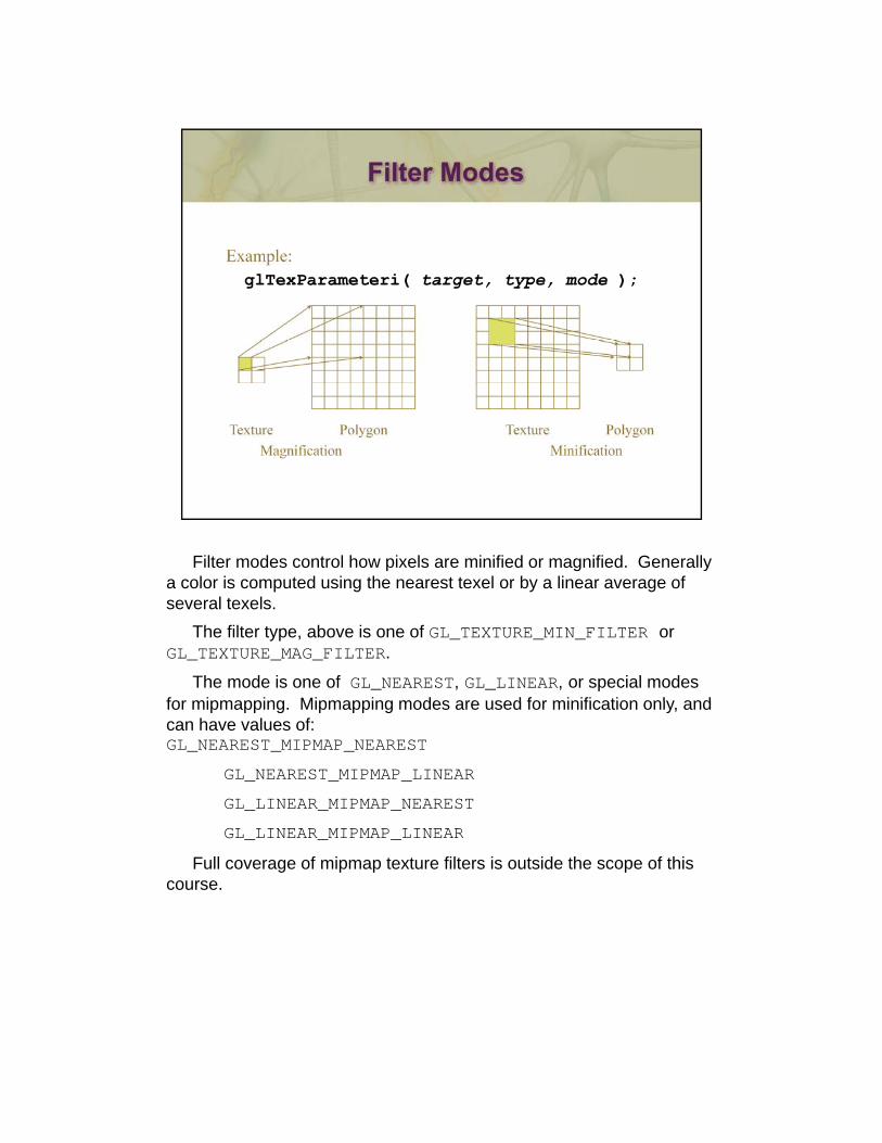
Filter modes control how pixels are minified or magnified. Generally a color is computed using the nearest texel or by a linear average of several texels.
The filter type, above is one of GL_TEXTURE_MIN_FILTER or GL_TEXTURE_MAG_FILTER.
The mode is one of GL_NEAREST, GL_LINEAR, or special modes for mipmapping Mipmapping modes are used for minification only andfor mipmapping. Mipmapping modes are used for minification only, and can have values of:GL_NEAREST_MIPMAP_NEAREST
GL_NEAREST_MIPMAP_LINEAR
GL_LINEAR_MIPMAP_NEAREST
GL LINEAR MIPMAP LINEARGL_LINEAR_MIPMAP_LINEAR
Full coverage of mipmap texture filters is outside the scope of this course.
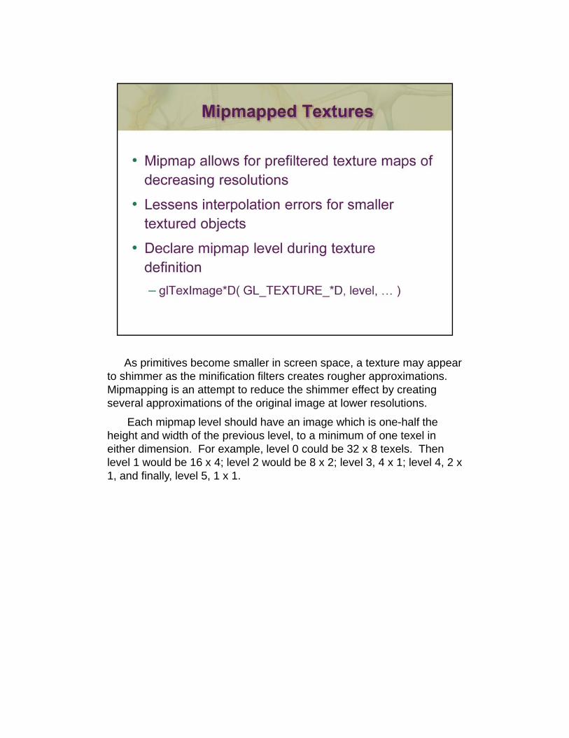
As primitives become smaller in screen space, a texture may appear to shimmer as the minification filters creates rougher approximations. Mipmapping is an attempt to reduce the shimmer effect by creating several approximations of the original image at lower resolutions.
Each mipmap level should have an image which is one-half the height and width of the previous level, to a minimum of one texel in either dimension. For example, level 0 could be 32 x 8 texels. Then p ,level 1 would be 16 x 4; level 2 would be 8 x 2; level 3, 4 x 1; level 4, 2 x 1, and finally, level 5, 1 x 1.
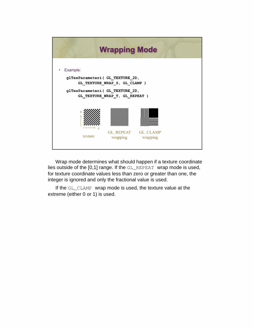
Wrap mode determines what should happen if a texture coordinate lies outside of the [0,1] range. If the GL_REPEAT wrap mode is used, for texture coordinate values less than zero or greater than one, the integer is ignored and only the fractional value is used.
If the GL_CLAMP wrap mode is used, the texture value at the extreme (either 0 or 1) is used.

100
101 101

102
103

This is the shader from are earlier example with the addition of the modelviewprojection matrix to allow for viewing and transformation from model coordinates. Shading is left to the fragment shader.
104
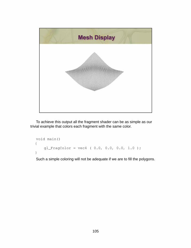
To achieve this output all the fragment shader can be as simple as our trivial example that colors each fragment with the same color.
void main() {
gl_FragColor = vec4 ( 0.0, 0.0, 0.0, 1.0 );}}
Such a simple coloring will not be adequate if we are to fill the polygons.
105
If we don’t add lighting, we will see a solid black mesh and won’t be able to see shape.
106 106
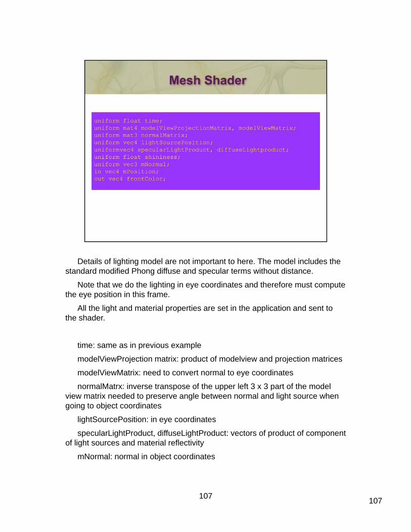
Details of lighting model are not important to here. The model includes the standard modified Phong diffuse and specular terms without distance.
Note that we do the lighting in eye coordinates and therefore must compute the eye position in this frame.
All the light and material properties are set in the application and sent to the shader.
time: same as in previous example
modelViewProjection matrix: product of modelview and projection matrices
modelViewMatrix: need to convert normal to eye coordinates
normalMatrx: inverse transpose of the upper left 3 x 3 part of the modelnormalMatrx: inverse transpose of the upper left 3 x 3 part of the model view matrix needed to preserve angle between normal and light source when going to object coordinates
lightSourcePosition: in eye coordinates
specularLightProduct, diffuseLightProduct: vectors of product of component of light sources and material reflectivity
107
mNormal: normal in object coordinates
107
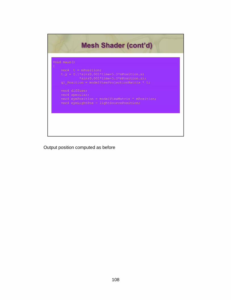
Output position computed as before
108
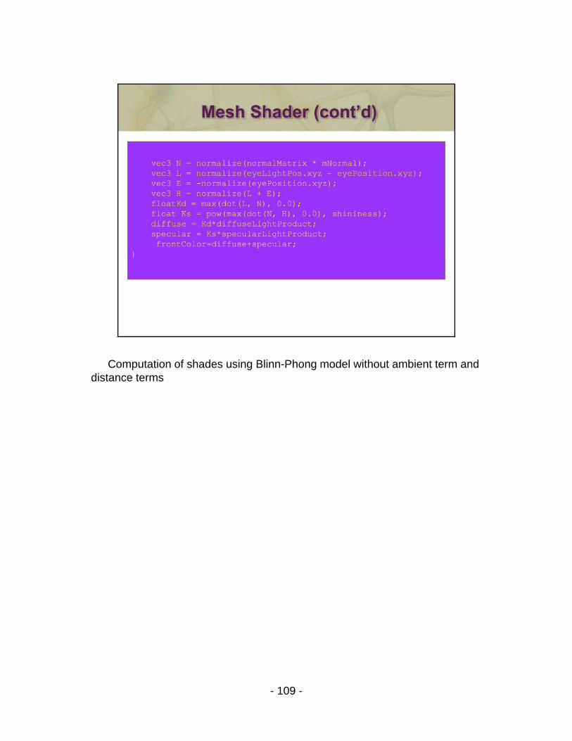
Computation of shades using Blinn-Phong model without ambient term and distance terms
- 109 -
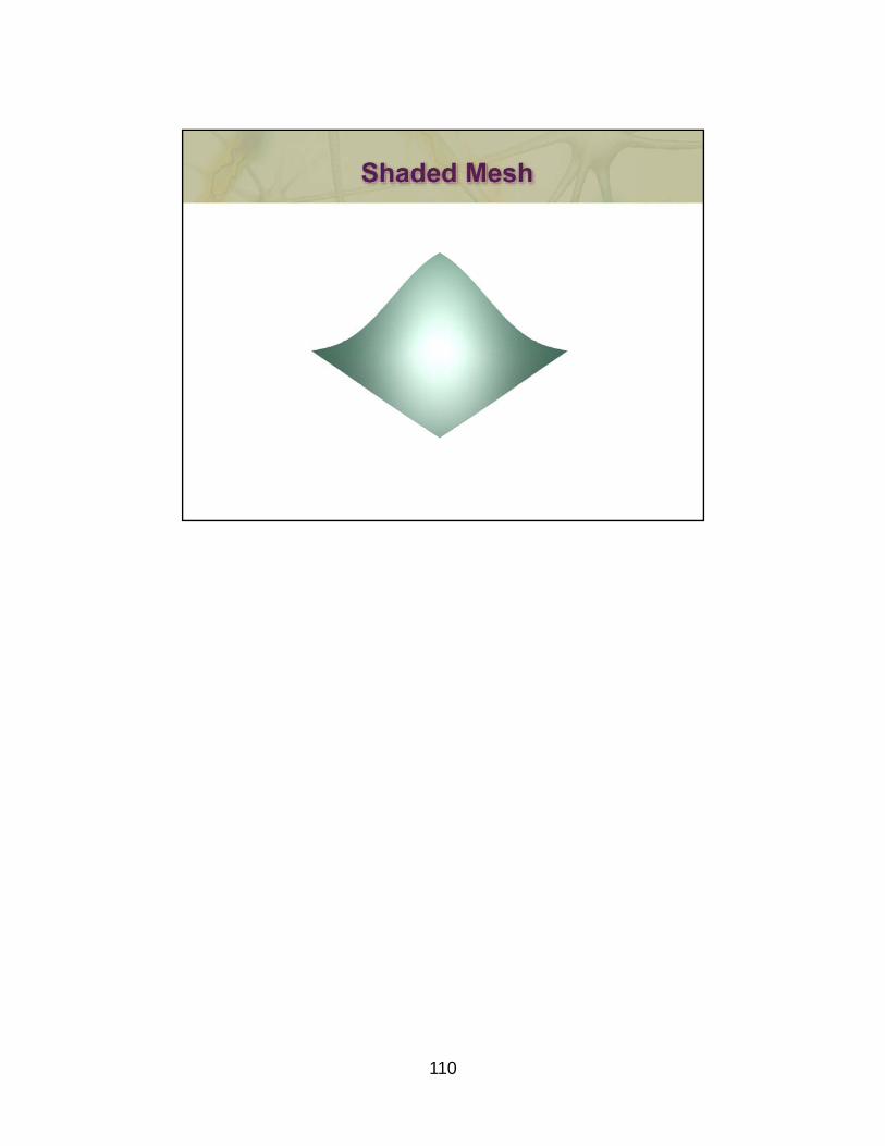
110

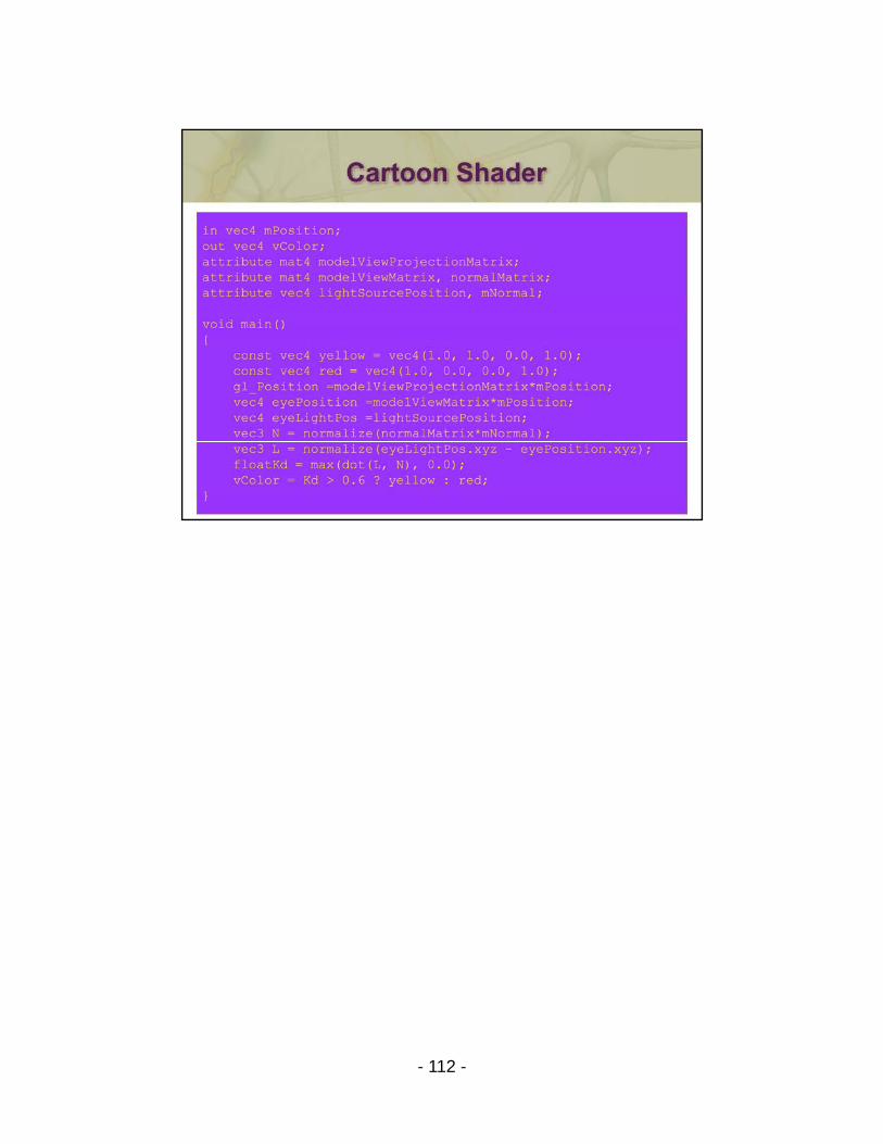
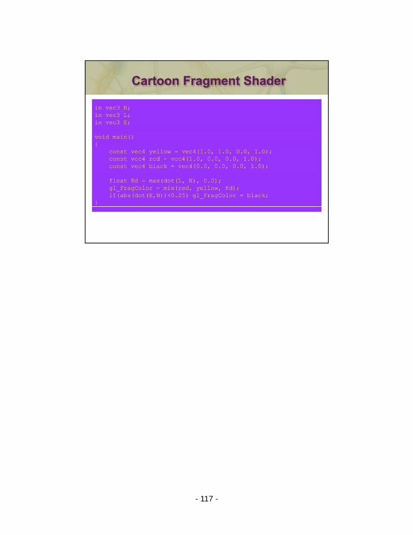
In this example, we use some of the standard diffuse computation to find the cosine of the angle between the light vector and the normal vector. Its value determines whether we color with red or yellow.
A silhouette edge is computed as in the previous example.
111 111
- 112 -
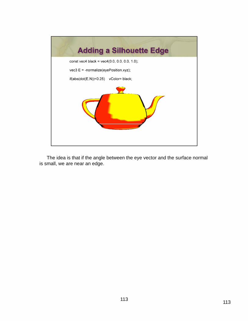
The idea is that if the angle between the eye vector and the surface normal is small, we are near an edge.
113 113
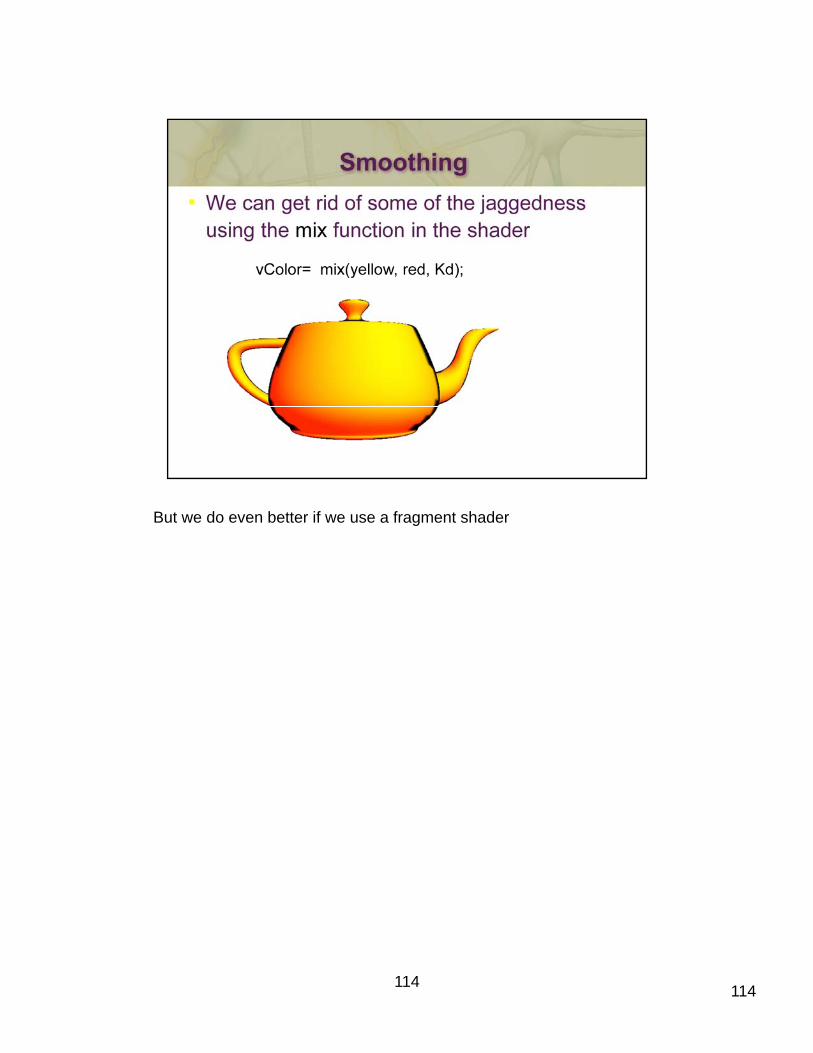
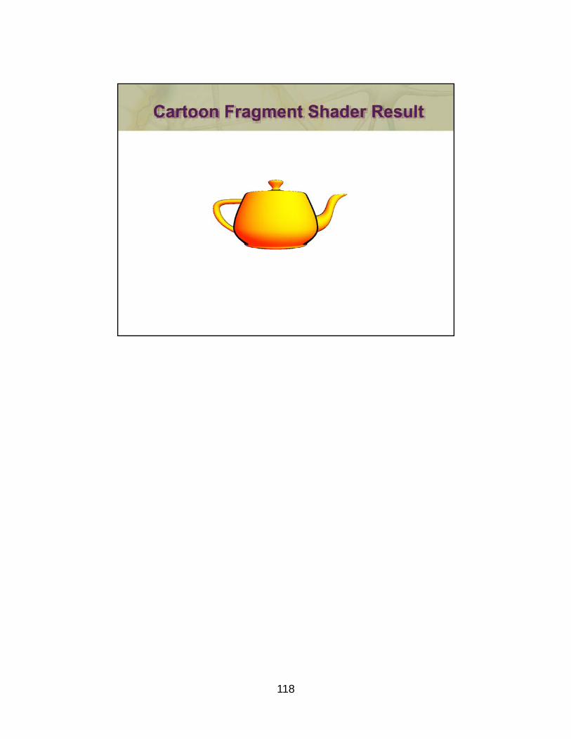
But we do even better if we use a fragment shader
114 114
115
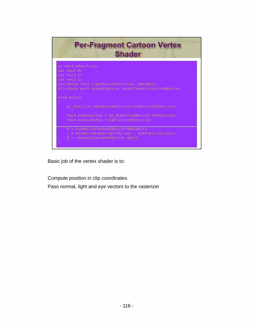
Basic job of the vertex shader is to:
Compute position in clip coordinates
Pass normal, light and eye vectors to the rasterizer
- 116 -
- 117 -
118
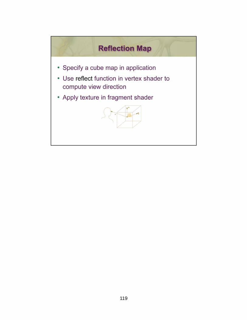
119
- 120 -
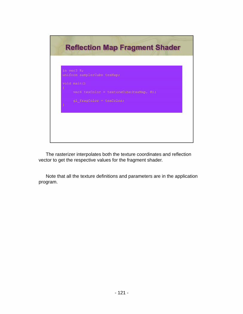
The rasterizer interpolates both the texture coordinates and reflection vector to get the respective values for the fragment shader.
Note that all the texture definitions and parameters are in the application program.
- 121 -
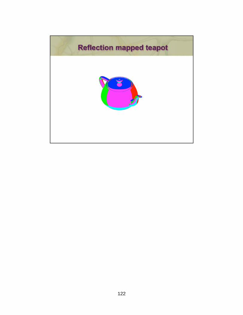
122
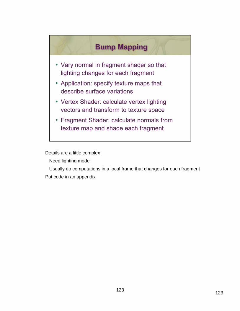
Details are a little complex
Need lighting model
Usually do computations in a local frame that changes for each fragment
Put code in an appendix
123 123
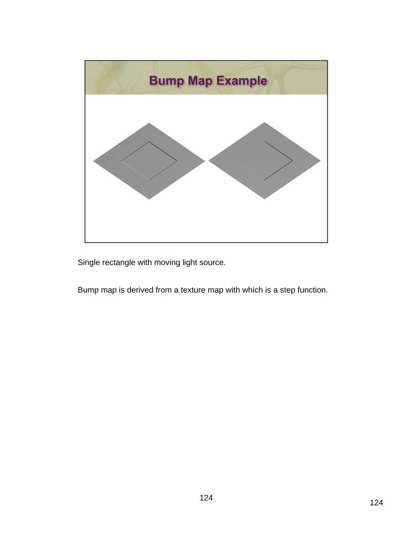
Single rectangle with moving light source.
Bump map is derived from a texture map with which is a step function.
124 124

- 125 -

- 126 -
127
The OpenGL Programming Guide– often referred to as the “Red Book” due to the color of its cover – discusses all aspects of OpenGL programming, discussing all of the features of OpenGL in detail.
Mark Kilgard’s OpenGL Programming for the X Window System, is the “Green Book”, and Ron Fosner’s OpenGL Programming for Microsoft Windows, which has a white cover is sometimes called the “Alpha Book.” The OpenGL Shading Language, by Randi Rost, Barthold p p g g g , y ,Litchenbelt, and John Kessenich, is the “Orange Book.”
All of the OpenGL programming series books, along with Interactive Computer Graphics: A top-down approach with OpenGL, OpenGL: A Primer, and OpenGL Distilled are published by Addison Wesley Publishers.
128

SIGGRAPH 2009 An Introduction to Shader‐Based OpenGL Programming
Program Listing
‐ 130 ‐
triangle.cxx
////////////////////////////////////////////////////////////////////////////// // // triangle.cxx ‐ draw a single triangle in normalized‐device coordinates // 5 #include <stdlib.h> #include <GL/glew.h> #ifdef MACOSX #include <GLUT/glut.h> 10 #else #include <GL/freeglut.h> #endif #include "LoadProgram.h" 15 #define BUFFER_OFFSET( offset ) ((GLvoid*) offset) GLuint buffer; GLuint vPos; 20 GLuint program; //‐‐‐‐‐‐‐‐‐‐‐‐‐‐‐‐‐‐‐‐‐‐‐‐‐‐‐‐‐‐‐‐‐‐‐‐‐‐‐‐‐‐‐‐‐‐‐‐‐‐‐‐‐‐‐‐‐‐‐‐‐‐‐‐‐‐‐‐‐‐‐‐‐‐‐‐ 25 void init() { // // ‐‐‐ Load vertex data ‐‐‐ 30 // GLfloat vertices[][4] = { { ‐0.75, ‐0.5, 0.0, 1.0 }, { 0.75, ‐0.5, 0.0, 1.0 }, { 0.0, 0.75, 0.0, 1.0 } 35 }; glGenBuffers( 1, &buffer ); glBindBuffer( GL_ARRAY_BUFFER, buffer ); glBufferData( GL_ARRAY_BUFFER, sizeof(vertices), 40 vertices, GL_STATIC_DRAW ); // // ‐‐‐ Load shaders ‐‐‐ // 45 #if GLSL_VERSION == 130 const char* vShader = { "#version 130\n" "" 50 "in vec4 vPos;" "" "void main() {" " gl_Position = vPos;" "}" 55 }; const char* fShader = { "#version 130\n"
‐ 131 ‐
"" 60 "out vec4 fColor;" "" "void main() {" " fColor = vec4( 1, 1, 0, 1 );" "}" 65 }; #else const char* vShader = { "attribute vec4 vPos;" "" 70 "void main() {" " gl_Position = vPos;" "}" }; 75 const char* fShader = { "void main() {" " gl_FragColor = vec4( 1, 1, 0, 1 );" "}" }; 80 #endif // SHADER_VERSION == 130 program = LoadProgram( vShader, fShader ); 85 vPos = glGetAttribLocation( program, "vPos" ); glClearColor( 0.0, 0.0, 1.0, 1.0 ); } 90 //‐‐‐‐‐‐‐‐‐‐‐‐‐‐‐‐‐‐‐‐‐‐‐‐‐‐‐‐‐‐‐‐‐‐‐‐‐‐‐‐‐‐‐‐‐‐‐‐‐‐‐‐‐‐‐‐‐‐‐‐‐‐‐‐‐‐‐‐‐‐‐‐‐‐‐‐ void display() { 95 glClear( GL_COLOR_BUFFER_BIT ); glUseProgram( program ); glBindBuffer( GL_ARRAY_BUFFER, buffer ); 100 glVertexAttribPointer( vPos, 4, GL_FLOAT, GL_FALSE, 0, BUFFER_OFFSET(0) ); glEnableVertexAttribArray( vPos ); glDrawArrays( GL_TRIANGLES, 0, 3 ); glutSwapBuffers(); 105 } //‐‐‐‐‐‐‐‐‐‐‐‐‐‐‐‐‐‐‐‐‐‐‐‐‐‐‐‐‐‐‐‐‐‐‐‐‐‐‐‐‐‐‐‐‐‐‐‐‐‐‐‐‐‐‐‐‐‐‐‐‐‐‐‐‐‐‐‐‐‐‐‐‐‐‐‐ void 110 reshape( int width, int height ) { glViewport( 0, 0, width, height ); } 115 //‐‐‐‐‐‐‐‐‐‐‐‐‐‐‐‐‐‐‐‐‐‐‐‐‐‐‐‐‐‐‐‐‐‐‐‐‐‐‐‐‐‐‐‐‐‐‐‐‐‐‐‐‐‐‐‐‐‐‐‐‐‐‐‐‐‐‐‐‐‐‐‐‐‐‐‐ void keyboard( unsigned char key, int x, int y ) { 120
‐ 132 ‐
switch( key ) { case 033: // Escape Key exit( EXIT_SUCCESS ); break; } 125 glutPostRedisplay(); } //‐‐‐‐‐‐‐‐‐‐‐‐‐‐‐‐‐‐‐‐‐‐‐‐‐‐‐‐‐‐‐‐‐‐‐‐‐‐‐‐‐‐‐‐‐‐‐‐‐‐‐‐‐‐‐‐‐‐‐‐‐‐‐‐‐‐‐‐‐‐‐‐‐‐‐‐ 130 int main( int argc, char* argv[] ) { glutInit( &argc, argv ); 135 glutInitDisplayMode( GLUT_RGBA | GLUT_DOUBLE ); // glutInitContextVersion( 3, 0 ); glutCreateWindow( argv[0] ); glewInit(); 140 init(); glutDisplayFunc( display ); glutReshapeFunc( reshape ); 145 glutKeyboardFunc( keyboard ); glutMainLoop(); } 150
‐ 133 ‐
colordrawarrays.cxx
////////////////////////////////////////////////////////////////////////////// // // color‐draw‐arrays.cxx ‐ draw a cube using glDrawArrays() with two // vertex attribute arrays enabled: one for positions, and the other 5 // for colors. // #include <stdlib.h> #include <GL/glew.h> 10 #ifdef MACOSX #include <GLUT/glut.h> #else #include <GL/freeglut.h> #endif 15 #include "LoadProgram.h" #define BUFFER_OFFSET( offset ) ((GLvoid*) offset) 20 GLuint vbo; GLuint program; GLuint vPos, vColor; GLintptr colorOffset; 25 //‐‐‐‐‐‐‐‐‐‐‐‐‐‐‐‐‐‐‐‐‐‐‐‐‐‐‐‐‐‐‐‐‐‐‐‐‐‐‐‐‐‐‐‐‐‐‐‐‐‐‐‐‐‐‐‐‐‐‐‐‐‐‐‐‐‐‐‐‐‐‐‐‐‐‐‐ void init() 30 { GLfloat vertices[] = { 1.0, 0.0, 0.0, /* Index 4 */ 1.0, 0.0, 1.0, /* Index 5 */ 1.0, 1.0, 1.0, /* Index 7 */ 35 1.0, 0.0, 0.0, /* Index 4 */ 1.0, 1.0, 1.0, /* Index 7 */ 1.0, 1.0, 0.0, /* Index 6 */ 40 0.0, 0.0, 0.0, /* Index 0 */ 0.0, 1.0, 0.0, /* Index 2 */ 0.0, 1.0, 1.0, /* Index 3 */ 0.0, 0.0, 0.0, /* Index 0 */ 45 0.0, 1.0, 1.0, /* Index 3 */ 0.0, 0.0, 1.0, /* Index 1 */ 0.0, 1.0, 0.0, /* Index 2 */ 1.0, 1.0, 0.0, /* Index 6 */ 50 1.0, 1.0, 1.0, /* Index 7 */ 0.0, 1.0, 0.0, /* Index 2 */ 1.0, 1.0, 1.0, /* Index 7 */ 0.0, 1.0, 1.0, /* Index 3 */ 55 0.0, 0.0, 0.0, /* Index 0 */ 0.0, 0.0, 1.0, /* Index 1 */
‐ 134 ‐
1.0, 0.0, 1.0, /* Index 5 */ 60 0.0, 0.0, 0.0, /* Index 0 */ 1.0, 0.0, 1.0, /* Index 5 */ 1.0, 0.0, 0.0, /* Index 4 */ 0.0, 0.0, 0.0, /* Index 0 */ 65 1.0, 0.0, 0.0, /* Index 4 */ 1.0, 1.0, 0.0, /* Index 6 */ 0.0, 0.0, 0.0, /* Index 0 */ 1.0, 1.0, 0.0, /* Index 6 */ 70 0.0, 1.0, 0.0, /* Index 2 */ 0.0, 0.0, 1.0, /* Index 1 */ 0.0, 1.0, 1.0, /* Index 3 */ 1.0, 1.0, 1.0, /* Index 7 */ 75 0.0, 0.0, 1.0, /* Index 1 */ 1.0, 1.0, 1.0, /* Index 7 */ 1.0, 0.0, 1.0, /* Index 5 */ }; 80 GLfloat colors[] = { 1.0, 0.0, 0.0, /* Index 4 */ 1.0, 0.0, 1.0, /* Index 5 */ 1.0, 1.0, 1.0, /* Index 7 */ 85 1.0, 0.0, 0.0, /* Index 4 */ 1.0, 1.0, 1.0, /* Index 7 */ 1.0, 1.0, 0.0, /* Index 6 */ 90 0.0, 0.0, 0.0, /* Index 0 */ 0.0, 1.0, 0.0, /* Index 2 */ 0.0, 1.0, 1.0, /* Index 3 */ 0.0, 0.0, 0.0, /* Index 0 */ 95 0.0, 1.0, 1.0, /* Index 3 */ 0.0, 0.0, 1.0, /* Index 1 */ 0.0, 1.0, 0.0, /* Index 2 */ 1.0, 1.0, 0.0, /* Index 6 */ 100 1.0, 1.0, 1.0, /* Index 7 */ 0.0, 1.0, 0.0, /* Index 2 */ 1.0, 1.0, 1.0, /* Index 7 */ 0.0, 1.0, 1.0, /* Index 3 */ 105 0.0, 0.0, 0.0, /* Index 0 */ 0.0, 0.0, 1.0, /* Index 1 */ 1.0, 0.0, 1.0, /* Index 5 */ 110 0.0, 0.0, 0.0, /* Index 0 */ 1.0, 0.0, 1.0, /* Index 5 */ 1.0, 0.0, 0.0, /* Index 4 */ 0.0, 0.0, 0.0, /* Index 0 */ 115 1.0, 0.0, 0.0, /* Index 4 */ 1.0, 1.0, 0.0, /* Index 6 */ 0.0, 0.0, 0.0, /* Index 0 */
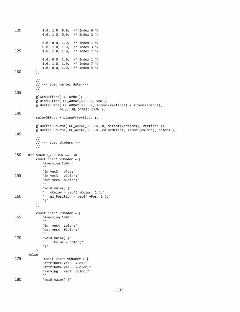
‐ 135 ‐
1.0, 1.0, 0.0, /* Index 6 */ 120 0.0, 1.0, 0.0, /* Index 2 */ 0.0, 0.0, 1.0, /* Index 1 */ 0.0, 1.0, 1.0, /* Index 3 */ 1.0, 1.0, 1.0, /* Index 7 */ 125 0.0, 0.0, 1.0, /* Index 1 */ 1.0, 1.0, 1.0, /* Index 7 */ 1.0, 0.0, 1.0, /* Index 5 */ }; 130 // // ‐‐‐ Load vertex data ‐‐‐ // 135 glGenBuffers( 1, &vbo ); glBindBuffer( GL_ARRAY_BUFFER, vbo ); glBufferData( GL_ARRAY_BUFFER, sizeof(vertices) + sizeof(colors), NULL, GL_STATIC_DRAW ); 140 colorOffset = sizeof(vertices ); glBufferSubData( GL_ARRAY_BUFFER, 0, sizeof(vertices), vertices ); glBufferSubData( GL_ARRAY_BUFFER, colorOffset, sizeof(colors), colors ); 145 // // ‐‐‐ Load shaders ‐‐‐ // #if SHADER_VERSION == 130 150 const char* vShader = { "#version 130\n" "" "in vec3 vPos;" "in vec3 vColor;" 155 "out vec4 oColor;" "" "void main() {" " oColor = vec4( vColor, 1 );" " gl_Position = vec4( vPos, 1 );" 160 "}" }; const char* fShader = { "#version 130\n" 165 "" "in vec4 color;" "out vec4 fColor;" "" "void main() {" 170 " fColor = color;" "}" }; #else const char* vShader = { 175 "attribute vec3 vPos;" "attribute vec3 vColor;" "varying vec4 color;" "" "void main() {" 180
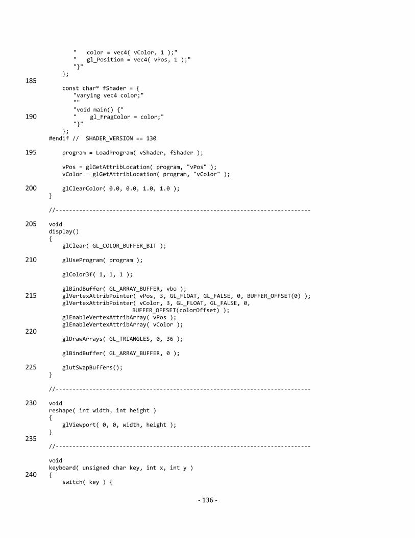
‐ 136 ‐
" color = vec4( vColor, 1 );" " gl_Position = vec4( vPos, 1 );" "}" }; 185 const char* fShader = { "varying vec4 color;" "" "void main() {" " gl_FragColor = color;" 190 "}" }; #endif // SHADER_VERSION == 130 program = LoadProgram( vShader, fShader ); 195 vPos = glGetAttribLocation( program, "vPos" ); vColor = glGetAttribLocation( program, "vColor" ); glClearColor( 0.0, 0.0, 1.0, 1.0 ); 200 } //‐‐‐‐‐‐‐‐‐‐‐‐‐‐‐‐‐‐‐‐‐‐‐‐‐‐‐‐‐‐‐‐‐‐‐‐‐‐‐‐‐‐‐‐‐‐‐‐‐‐‐‐‐‐‐‐‐‐‐‐‐‐‐‐‐‐‐‐‐‐‐‐‐‐‐‐ void 205 display() { glClear( GL_COLOR_BUFFER_BIT ); glUseProgram( program ); 210 glColor3f( 1, 1, 1 ); glBindBuffer( GL_ARRAY_BUFFER, vbo ); glVertexAttribPointer( vPos, 3, GL_FLOAT, GL_FALSE, 0, BUFFER_OFFSET(0) ); 215 glVertexAttribPointer( vColor, 3, GL_FLOAT, GL_FALSE, 0, BUFFER_OFFSET(colorOffset) ); glEnableVertexAttribArray( vPos ); glEnableVertexAttribArray( vColor ); 220 glDrawArrays( GL_TRIANGLES, 0, 36 ); glBindBuffer( GL_ARRAY_BUFFER, 0 ); glutSwapBuffers(); 225 } //‐‐‐‐‐‐‐‐‐‐‐‐‐‐‐‐‐‐‐‐‐‐‐‐‐‐‐‐‐‐‐‐‐‐‐‐‐‐‐‐‐‐‐‐‐‐‐‐‐‐‐‐‐‐‐‐‐‐‐‐‐‐‐‐‐‐‐‐‐‐‐‐‐‐‐‐ void 230 reshape( int width, int height ) { glViewport( 0, 0, width, height ); } 235 //‐‐‐‐‐‐‐‐‐‐‐‐‐‐‐‐‐‐‐‐‐‐‐‐‐‐‐‐‐‐‐‐‐‐‐‐‐‐‐‐‐‐‐‐‐‐‐‐‐‐‐‐‐‐‐‐‐‐‐‐‐‐‐‐‐‐‐‐‐‐‐‐‐‐‐‐ void keyboard( unsigned char key, int x, int y ) { 240 switch( key ) {

‐ 137 ‐
case 033: // Escape Key exit( EXIT_SUCCESS ); break; } 245 glutPostRedisplay(); } //‐‐‐‐‐‐‐‐‐‐‐‐‐‐‐‐‐‐‐‐‐‐‐‐‐‐‐‐‐‐‐‐‐‐‐‐‐‐‐‐‐‐‐‐‐‐‐‐‐‐‐‐‐‐‐‐‐‐‐‐‐‐‐‐‐‐‐‐‐‐‐‐‐‐‐‐ 250 int main( int argc, char* argv[] ) { glutInit( &argc, argv ); 255 glutInitDisplayMode( GLUT_RGBA | GLUT_DOUBLE ); // glutInitContextVersion( 3, 0 ); glutCreateWindow( argv[0] ); glewInit(); 260 init(); glutDisplayFunc( display ); glutReshapeFunc( reshape ); 265 glutKeyboardFunc( keyboard ); glutMainLoop(); } 270
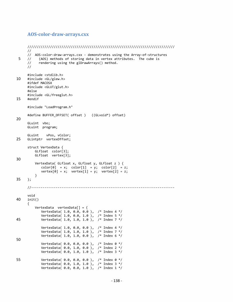
‐ 138 ‐
AOScolordrawarrays.cxx
////////////////////////////////////////////////////////////////////////////// // // AOS‐color‐draw‐arrays.cxx ‐ demonstrates using the Array‐of‐structures // (AOS) methods of storing data in vertex attributes. The cube is 5 // rendering using the glDrawArrays() method. // #include <stdlib.h> #include <GL/glew.h> 10 #ifdef MACOSX #include <GLUT/glut.h> #else #include <GL/freeglut.h> #endif 15 #include "LoadProgram.h" #define BUFFER_OFFSET( offset ) ((GLvoid*) offset) 20 GLuint vbo; GLuint program; GLuint vPos, vColor; GLintptr vertexOffset; 25 struct VertexData { GLfloat color[3]; GLfloat vertex[3]; 30 VertexData( GLfloat x, GLfloat y, GLfloat z ) { color[0] = x; color[1] = y; color[2] = z; vertex[0] = x; vertex[1] = y; vertex[2] = z; } }; 35 //‐‐‐‐‐‐‐‐‐‐‐‐‐‐‐‐‐‐‐‐‐‐‐‐‐‐‐‐‐‐‐‐‐‐‐‐‐‐‐‐‐‐‐‐‐‐‐‐‐‐‐‐‐‐‐‐‐‐‐‐‐‐‐‐‐‐‐‐‐‐‐‐‐‐‐‐ void init() 40 { VertexData vertexData[] = { VertexData( 1.0, 0.0, 0.0 ), /* Index 4 */ VertexData( 1.0, 0.0, 1.0 ), /* Index 5 */ VertexData( 1.0, 1.0, 1.0 ), /* Index 7 */ 45 VertexData( 1.0, 0.0, 0.0 ), /* Index 4 */ VertexData( 1.0, 1.0, 1.0 ), /* Index 7 */ VertexData( 1.0, 1.0, 0.0 ), /* Index 6 */ 50 VertexData( 0.0, 0.0, 0.0 ), /* Index 0 */ VertexData( 0.0, 1.0, 0.0 ), /* Index 2 */ VertexData( 0.0, 1.0, 1.0 ), /* Index 3 */ VertexData( 0.0, 0.0, 0.0 ), /* Index 0 */ 55 VertexData( 0.0, 1.0, 1.0 ), /* Index 3 */ VertexData( 0.0, 0.0, 1.0 ), /* Index 1 */
‐ 139 ‐
VertexData( 0.0, 1.0, 0.0 ), /* Index 2 */ VertexData( 1.0, 1.0, 0.0 ), /* Index 6 */ 60 VertexData( 1.0, 1.0, 1.0 ), /* Index 7 */ VertexData( 0.0, 1.0, 0.0 ), /* Index 2 */ VertexData( 1.0, 1.0, 1.0 ), /* Index 7 */ VertexData( 0.0, 1.0, 1.0 ), /* Index 3 */ 65 VertexData( 0.0, 0.0, 0.0 ), /* Index 0 */ VertexData( 0.0, 0.0, 1.0 ), /* Index 1 */ VertexData( 1.0, 0.0, 1.0 ), /* Index 5 */ 70 VertexData( 0.0, 0.0, 0.0 ), /* Index 0 */ VertexData( 1.0, 0.0, 1.0 ), /* Index 5 */ VertexData( 1.0, 0.0, 0.0 ), /* Index 4 */ VertexData( 0.0, 0.0, 0.0 ), /* Index 0 */ 75 VertexData( 1.0, 0.0, 0.0 ), /* Index 4 */ VertexData( 1.0, 1.0, 0.0 ), /* Index 6 */ VertexData( 0.0, 0.0, 0.0 ), /* Index 0 */ VertexData( 1.0, 1.0, 0.0 ), /* Index 6 */ 80 VertexData( 0.0, 1.0, 0.0 ), /* Index 2 */ VertexData( 0.0, 0.0, 1.0 ), /* Index 1 */ VertexData( 0.0, 1.0, 1.0 ), /* Index 3 */ VertexData( 1.0, 1.0, 1.0 ), /* Index 7 */ 85 VertexData( 0.0, 0.0, 1.0 ), /* Index 1 */ VertexData( 1.0, 1.0, 1.0 ), /* Index 7 */ VertexData( 1.0, 0.0, 1.0 ), /* Index 5 */ }; 90 vertexOffset = sizeof(vertexData[0].color); // // ‐‐‐ Load vertex data ‐‐‐ 95 // glGenBuffers( 1, &vbo ); glBindBuffer( GL_ARRAY_BUFFER, vbo ); glBufferData( GL_ARRAY_BUFFER, sizeof(vertexData), 100 vertexData, GL_STATIC_DRAW ); // // ‐‐‐ Load shaders ‐‐‐ // 105 #if SHADER_VERSION == 130 const char* vShader = { "#version 130\n" "" 110 "in vec3 vPos;" "in vec3 vColor;" "out vec4 oColor;" "" "void main() {" 115 " oColor = vec4( vColor, 1 );" " gl_Position = vec4( vPos, 1 );" "}" };
‐ 140 ‐
120 const char* fShader = { "#version 130\n" "" "in vec4 color;" "out vec4 fColor;" 125 "" "void main() {" " fColor = color;" "}" }; 130 #else const char* vShader = { "attribute vec3 vPos;" "attribute vec3 vColor;" "varying vec4 color;" 135 "" "void main() {" " color = vec4( vColor, 1 );" " gl_Position = vec4( vPos, 1 );" "}" 140 }; const char* fShader = { "varying vec4 color;" "" 145 "void main() {" " gl_FragColor = color;" "}" }; #endif // SHADER_VERSION == 130 150 program = LoadProgram( vShader, fShader ); vPos = glGetAttribLocation( program, "vPos" ); vColor = glGetAttribLocation( program, "vColor" ); 155 glClearColor( 0.0, 0.0, 1.0, 1.0 ); } //‐‐‐‐‐‐‐‐‐‐‐‐‐‐‐‐‐‐‐‐‐‐‐‐‐‐‐‐‐‐‐‐‐‐‐‐‐‐‐‐‐‐‐‐‐‐‐‐‐‐‐‐‐‐‐‐‐‐‐‐‐‐‐‐‐‐‐‐‐‐‐‐‐‐‐‐ 160 void display() { glClear( GL_COLOR_BUFFER_BIT ); 165 glUseProgram( program ); glColor3f( 1, 1, 1 ); 170 glBindBuffer( GL_ARRAY_BUFFER, vbo ); glVertexAttribPointer( vColor, 3, GL_FLOAT, GL_FALSE, sizeof(VertexData), BUFFER_OFFSET(0) ); glVertexAttribPointer( vPos, 3, GL_FLOAT, GL_FALSE, sizeof(VertexData), BUFFER_OFFSET(vertexOffset) ); 175 glEnableVertexAttribArray( vPos ); glEnableVertexAttribArray( vColor ); glDrawArrays( GL_TRIANGLES, 0, 36 ); 180
‐ 141 ‐
glBindBuffer( GL_ARRAY_BUFFER, 0 ); glutSwapBuffers(); } 185 //‐‐‐‐‐‐‐‐‐‐‐‐‐‐‐‐‐‐‐‐‐‐‐‐‐‐‐‐‐‐‐‐‐‐‐‐‐‐‐‐‐‐‐‐‐‐‐‐‐‐‐‐‐‐‐‐‐‐‐‐‐‐‐‐‐‐‐‐‐‐‐‐‐‐‐‐ void reshape( int width, int height ) { 190 glViewport( 0, 0, width, height ); } //‐‐‐‐‐‐‐‐‐‐‐‐‐‐‐‐‐‐‐‐‐‐‐‐‐‐‐‐‐‐‐‐‐‐‐‐‐‐‐‐‐‐‐‐‐‐‐‐‐‐‐‐‐‐‐‐‐‐‐‐‐‐‐‐‐‐‐‐‐‐‐‐‐‐‐‐ 195 void keyboard( unsigned char key, int x, int y ) { switch( key ) { case 033: // Escape Key 200 exit( EXIT_SUCCESS ); break; } glutPostRedisplay(); 205 } //‐‐‐‐‐‐‐‐‐‐‐‐‐‐‐‐‐‐‐‐‐‐‐‐‐‐‐‐‐‐‐‐‐‐‐‐‐‐‐‐‐‐‐‐‐‐‐‐‐‐‐‐‐‐‐‐‐‐‐‐‐‐‐‐‐‐‐‐‐‐‐‐‐‐‐‐ int 210 main( int argc, char* argv[] ) { glutInit( &argc, argv ); glutInitDisplayMode( GLUT_RGBA | GLUT_DOUBLE ); // glutInitContextVersion( 3, 0 ); 215 glutCreateWindow( argv[0] ); glewInit(); init(); 220 glutDisplayFunc( display ); glutReshapeFunc( reshape ); glutKeyboardFunc( keyboard ); 225 glutMainLoop(); }
‐ 142 ‐
Drawelements.cxx
////////////////////////////////////////////////////////////////////////////// // // draw‐elements.cxx ‐ render a cube using glDrawElements() indexing into // a set of vertex attributes stored in array‐of‐structures (AOS) storage. // 5 #include <stdlib.h> #include <GL/glew.h> #ifdef MACOSX #include <GLUT/glut.h> 10 #else #include <GL/freeglut.h> #endif #include "LoadProgram.h" 15 #define BUFFER_OFFSET( offset ) ((GLvoid*) offset) enum { Vertices, Indices, NumBuffers }; 20 GLuint buffers[NumBuffers]; GLuint program; GLuint vPos, vColor; GLintptr vertexOffset; 25 struct VertexData { GLfloat color[3]; GLfloat vertex[3]; 30 VertexData( GLfloat x, GLfloat y, GLfloat z ) { color[0] = x; color[1] = y; color[2] = z; vertex[0] = x; vertex[1] = y; vertex[2] = z; } }; 35 //‐‐‐‐‐‐‐‐‐‐‐‐‐‐‐‐‐‐‐‐‐‐‐‐‐‐‐‐‐‐‐‐‐‐‐‐‐‐‐‐‐‐‐‐‐‐‐‐‐‐‐‐‐‐‐‐‐‐‐‐‐‐‐‐‐‐‐‐‐‐‐‐‐‐‐‐ void init() 40 { VertexData vertexData[] = { VertexData( 0.0, 0.0, 0.0 ), /* Index 0 */ VertexData( 0.0, 0.0, 1.0 ), /* Index 1 */ VertexData( 0.0, 1.0, 0.0 ), /* Index 2 */ 45 VertexData( 0.0, 1.0, 1.0 ), /* Index 3 */ VertexData( 1.0, 0.0, 0.0 ), /* Index 4 */ VertexData( 1.0, 0.0, 1.0 ), /* Index 5 */ VertexData( 1.0, 1.0, 0.0 ), /* Index 6 */ VertexData( 1.0, 1.0, 1.0 ), /* Index 7 */ 50 }; GLubyte indices[] = { 4, 5, 7, // +X face 4, 7, 6, 55 0, 2, 3, // ‐X face 0, 3, 1, 2, 6, 7, // +Y face
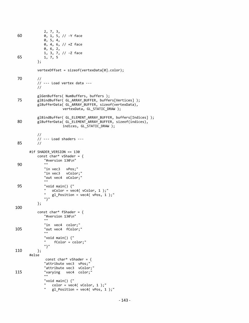
‐ 143 ‐
2, 7, 3, 0, 1, 5, // ‐Y face 60 0, 5, 4, 0, 4, 6, // +Z face 0, 6, 2, 1, 3, 7, // ‐Z face 1, 7, 5 65 }; vertexOffset = sizeof(vertexData[0].color); // 70 // ‐‐‐ Load vertex data ‐‐‐ // glGenBuffers( NumBuffers, buffers ); glBindBuffer( GL_ARRAY_BUFFER, buffers[Vertices] ); 75 glBufferData( GL_ARRAY_BUFFER, sizeof(vertexData), vertexData, GL_STATIC_DRAW ); glBindBuffer( GL_ELEMENT_ARRAY_BUFFER, buffers[Indices] ); glBufferData( GL_ELEMENT_ARRAY_BUFFER, sizeof(indices), 80 indices, GL_STATIC_DRAW ); // // ‐‐‐ Load shaders ‐‐‐ // 85 #if SHADER_VERSION == 130 const char* vShader = { "#version 130\n" "" 90 "in vec3 vPos;" "in vec3 vColor;" "out vec4 oColor;" "" "void main() {" 95 " oColor = vec4( vColor, 1 );" " gl_Position = vec4( vPos, 1 );" "}" }; 100 const char* fShader = { "#version 130\n" "" "in vec4 color;" "out vec4 fColor;" 105 "" "void main() {" " fColor = color;" "}" }; 110 #else const char* vShader = { "attribute vec3 vPos;" "attribute vec3 vColor;" "varying vec4 color;" 115 "" "void main() {" " color = vec4( vColor, 1 );" " gl_Position = vec4( vPos, 1 );"
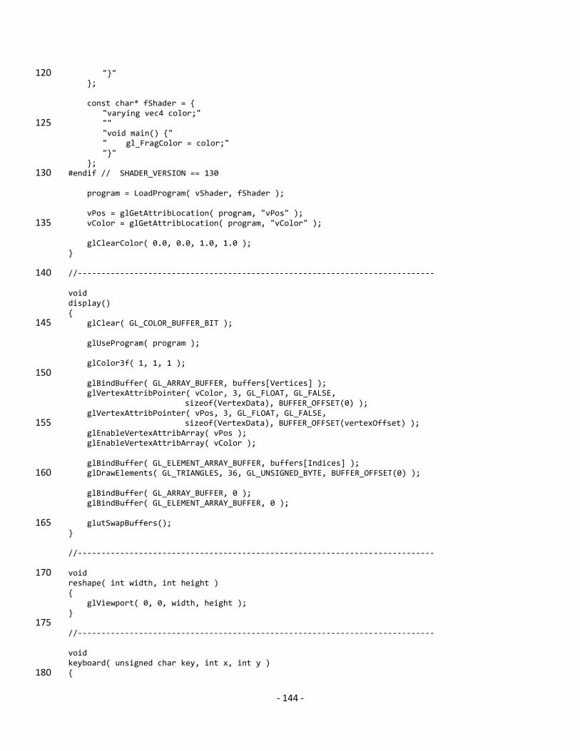
‐ 144 ‐
"}" 120 }; const char* fShader = { "varying vec4 color;" "" 125 "void main() {" " gl_FragColor = color;" "}" }; #endif // SHADER_VERSION == 130 130 program = LoadProgram( vShader, fShader ); vPos = glGetAttribLocation( program, "vPos" ); vColor = glGetAttribLocation( program, "vColor" ); 135 glClearColor( 0.0, 0.0, 1.0, 1.0 ); } //‐‐‐‐‐‐‐‐‐‐‐‐‐‐‐‐‐‐‐‐‐‐‐‐‐‐‐‐‐‐‐‐‐‐‐‐‐‐‐‐‐‐‐‐‐‐‐‐‐‐‐‐‐‐‐‐‐‐‐‐‐‐‐‐‐‐‐‐‐‐‐‐‐‐‐‐ 140 void display() { glClear( GL_COLOR_BUFFER_BIT ); 145 glUseProgram( program ); glColor3f( 1, 1, 1 ); 150 glBindBuffer( GL_ARRAY_BUFFER, buffers[Vertices] ); glVertexAttribPointer( vColor, 3, GL_FLOAT, GL_FALSE, sizeof(VertexData), BUFFER_OFFSET(0) ); glVertexAttribPointer( vPos, 3, GL_FLOAT, GL_FALSE, sizeof(VertexData), BUFFER_OFFSET(vertexOffset) ); 155 glEnableVertexAttribArray( vPos ); glEnableVertexAttribArray( vColor ); glBindBuffer( GL_ELEMENT_ARRAY_BUFFER, buffers[Indices] ); glDrawElements( GL_TRIANGLES, 36, GL_UNSIGNED_BYTE, BUFFER_OFFSET(0) ); 160 glBindBuffer( GL_ARRAY_BUFFER, 0 ); glBindBuffer( GL_ELEMENT_ARRAY_BUFFER, 0 ); glutSwapBuffers(); 165 } //‐‐‐‐‐‐‐‐‐‐‐‐‐‐‐‐‐‐‐‐‐‐‐‐‐‐‐‐‐‐‐‐‐‐‐‐‐‐‐‐‐‐‐‐‐‐‐‐‐‐‐‐‐‐‐‐‐‐‐‐‐‐‐‐‐‐‐‐‐‐‐‐‐‐‐‐ void 170 reshape( int width, int height ) { glViewport( 0, 0, width, height ); } 175 //‐‐‐‐‐‐‐‐‐‐‐‐‐‐‐‐‐‐‐‐‐‐‐‐‐‐‐‐‐‐‐‐‐‐‐‐‐‐‐‐‐‐‐‐‐‐‐‐‐‐‐‐‐‐‐‐‐‐‐‐‐‐‐‐‐‐‐‐‐‐‐‐‐‐‐‐ void keyboard( unsigned char key, int x, int y ) { 180
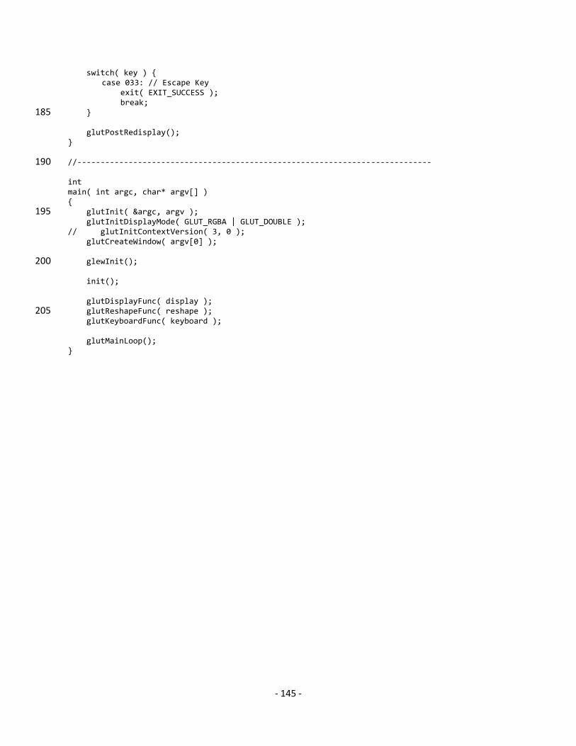
‐ 145 ‐
switch( key ) { case 033: // Escape Key exit( EXIT_SUCCESS ); break; } 185 glutPostRedisplay(); } //‐‐‐‐‐‐‐‐‐‐‐‐‐‐‐‐‐‐‐‐‐‐‐‐‐‐‐‐‐‐‐‐‐‐‐‐‐‐‐‐‐‐‐‐‐‐‐‐‐‐‐‐‐‐‐‐‐‐‐‐‐‐‐‐‐‐‐‐‐‐‐‐‐‐‐‐ 190 int main( int argc, char* argv[] ) { glutInit( &argc, argv ); 195 glutInitDisplayMode( GLUT_RGBA | GLUT_DOUBLE ); // glutInitContextVersion( 3, 0 ); glutCreateWindow( argv[0] ); glewInit(); 200 init(); glutDisplayFunc( display ); glutReshapeFunc( reshape ); 205 glutKeyboardFunc( keyboard ); glutMainLoop(); }
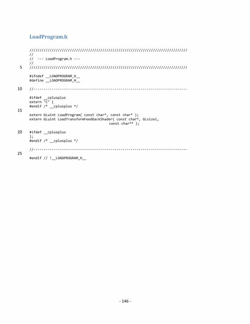
‐ 146 ‐
LoadProgram.h
////////////////////////////////////////////////////////////////////////////// // // ‐‐‐ LoadProgram.h ‐‐‐ // ////////////////////////////////////////////////////////////////////////////// 5 #ifndef __LOADPROGRAM_H__ #define __LOADPROGRAM_H__ //‐‐‐‐‐‐‐‐‐‐‐‐‐‐‐‐‐‐‐‐‐‐‐‐‐‐‐‐‐‐‐‐‐‐‐‐‐‐‐‐‐‐‐‐‐‐‐‐‐‐‐‐‐‐‐‐‐‐‐‐‐‐‐‐‐‐‐‐‐‐‐‐‐‐‐‐ 10 #ifdef __cplusplus extern "C" { #endif /* __cplusplus */ 15 extern GLuint LoadProgram( const char*, const char* ); extern GLuint LoadTransformFeedbackShader( const char*, GLsizei, const char** ); #ifdef __cplusplus 20 }; #endif /* __cplusplus */ //‐‐‐‐‐‐‐‐‐‐‐‐‐‐‐‐‐‐‐‐‐‐‐‐‐‐‐‐‐‐‐‐‐‐‐‐‐‐‐‐‐‐‐‐‐‐‐‐‐‐‐‐‐‐‐‐‐‐‐‐‐‐‐‐‐‐‐‐‐‐‐‐‐‐‐‐ 25 #endif // !__LOADPROGRAM_H__
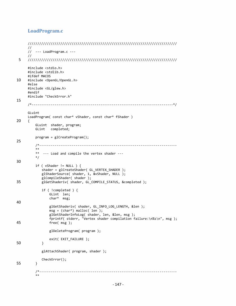
‐ 147 ‐
LoadProgram.c
////////////////////////////////////////////////////////////////////////////// // // ‐‐‐ LoadProgram.c ‐‐‐ // ////////////////////////////////////////////////////////////////////////////// 5 #include <stdio.h> #include <stdlib.h> #ifdef MACOS #include <OpenGL/OpenGL.h> 10 #else #include <GL/glew.h> #endif #include "CheckError.h" 15 /*‐‐‐‐‐‐‐‐‐‐‐‐‐‐‐‐‐‐‐‐‐‐‐‐‐‐‐‐‐‐‐‐‐‐‐‐‐‐‐‐‐‐‐‐‐‐‐‐‐‐‐‐‐‐‐‐‐‐‐‐‐‐‐‐‐‐‐‐‐‐‐‐‐‐*/ GLuint LoadProgram( const char* vShader, const char* fShader ) { 20 GLuint shader, program; GLint completed; program = glCreateProgram(); 25 /*‐‐‐‐‐‐‐‐‐‐‐‐‐‐‐‐‐‐‐‐‐‐‐‐‐‐‐‐‐‐‐‐‐‐‐‐‐‐‐‐‐‐‐‐‐‐‐‐‐‐‐‐‐‐‐‐‐‐‐‐‐‐‐‐‐‐‐‐‐‐‐‐ ** ** ‐‐‐ Load and compile the vertex shader ‐‐‐ */ 30 if ( vShader != NULL ) { shader = glCreateShader( GL_VERTEX_SHADER ); glShaderSource( shader, 1, &vShader, NULL ); glCompileShader( shader ); glGetShaderiv( shader, GL_COMPILE_STATUS, &completed ); 35 if ( !completed ) { GLint len; char* msg; 40 glGetShaderiv( shader, GL_INFO_LOG_LENGTH, &len ); msg = (char*) malloc( len ); glGetShaderInfoLog( shader, len, &len, msg ); fprintf( stderr, "Vertex shader compilation failure:\n%s\n", msg ); free( msg ); 45 glDeleteProgram( program ); exit( EXIT_FAILURE ); } 50 glAttachShader( program, shader ); CheckError(); } 55 /*‐‐‐‐‐‐‐‐‐‐‐‐‐‐‐‐‐‐‐‐‐‐‐‐‐‐‐‐‐‐‐‐‐‐‐‐‐‐‐‐‐‐‐‐‐‐‐‐‐‐‐‐‐‐‐‐‐‐‐‐‐‐‐‐‐‐‐‐‐‐‐‐ **
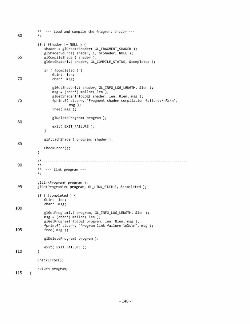
‐ 148 ‐
** ‐‐‐ Load and compile the fragment shader ‐‐‐ */ 60 if ( fShader != NULL ) { shader = glCreateShader( GL_FRAGMENT_SHADER ); glShaderSource( shader, 1, &fShader, NULL ); glCompileShader( shader ); 65 glGetShaderiv( shader, GL_COMPILE_STATUS, &completed ); if ( !completed ) { GLint len; char* msg; 70 glGetShaderiv( shader, GL_INFO_LOG_LENGTH, &len ); msg = (char*) malloc( len ); glGetShaderInfoLog( shader, len, &len, msg ); fprintf( stderr, "Fragment shader compilation failure:\n%s\n", 75 msg ); free( msg ); glDeleteProgram( program ); 80 exit( EXIT_FAILURE ); } glAttachShader( program, shader ); 85 CheckError(); } /*‐‐‐‐‐‐‐‐‐‐‐‐‐‐‐‐‐‐‐‐‐‐‐‐‐‐‐‐‐‐‐‐‐‐‐‐‐‐‐‐‐‐‐‐‐‐‐‐‐‐‐‐‐‐‐‐‐‐‐‐‐‐‐‐‐‐‐‐‐‐‐‐ ** 90 ** ‐‐‐ Link program ‐‐‐ */ glLinkProgram( program ); glGetProgramiv( program, GL_LINK_STATUS, &completed ); 95 if ( !completed ) { GLint len; char* msg; 100 glGetProgramiv( program, GL_INFO_LOG_LENGTH, &len ); msg = (char*) malloc( len ); glGetProgramInfoLog( program, len, &len, msg ); fprintf( stderr, "Program link failure:\n%s\n", msg ); free( msg ); 105 glDeleteProgram( program ); exit( EXIT_FAILURE ); } 110 CheckError(); return program; } 115