Validation and Verification of Thermo-Hydro-Mechanical (THM ...

Product Development & Global Technology
An Introduction to Hydro-mechanical Transmissions
Mike Cronin
28 Nov 2012 (Previously titled: “Cost Savings With Hydro-mechanical Transmissions”)

Product Development & Global Technology
Introduction
• Topics Covered: ▪ Speaker Background ▪ Simple Hydro-mechanical Transmission Schematic ▪ Current Industry Examples ▪ Important Design Characteristics ▪ How Fuel Is Saved ▪ Other Beneficial Characteristics
• Caveats:
▪ Not A Design Guide ▪ Limited To Off-road Perspective
Hydro-mechanical transmission architectures are growing in popularity as a cost effective means to provide continuously variable transmission (CVT) functionality in the heavy-duty off-road market segment. This presentation will introduce the audience to the basics of operation and commonly used terms.

Product Development & Global Technology
Mike Cronin’s CV • Joined Caterpillar upon graduation from Michigan State University with a
BSME in 1973
• Entire career working on off-road drivetrain performance and design: ▪ Hydro-mechanical transmissions for a broad range of applications ▪ Electric drive for TTT ▪ TTT & Belted machine steering systems and components ▪ Assorted lower powertrain projects ▪ Assorted powershift transmission concepts
• Drivetrain related patents
▪ 23 Granted ▪ 10 Pending ▪ 9 Notifications
• Retired in 2010
• Rejoined Caterpillar’s Drivetrain Research Dept on a part time basis to
continue work on hydro-mechanical drivetrains.
Product Development & Global Technology
Engine Gear
System Gear
System
Variator
Transfer Gear And/or Axle Reductions
Wheel Or
Sprocket
Transmission
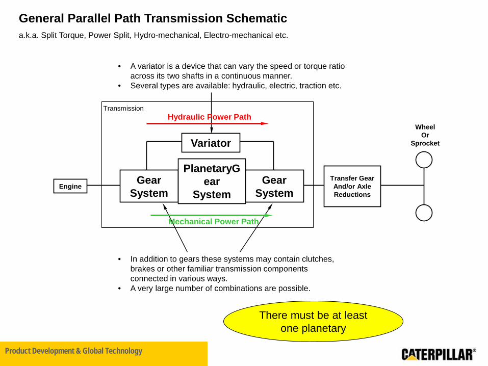
General Parallel Path Transmission Schematic a.k.a. Split Torque, Power Split, Hydro-mechanical, Electro-mechanical etc.
• A variator is a device that can vary the speed or torque ratio across its two shafts in a continuous manner.
• Several types are available: hydraulic, electric, traction etc.
• In addition to gears these systems may contain clutches, brakes or other familiar transmission components connected in various ways.
• A very large number of combinations are possible.
There must be at least one planetary
PlanetaryGear
System
Hydraulic Power Path
Mechanical Power Path

Product Development & Global Technology
Speed 1
Speed 2
General Planetary Gear System
Planetaries Are Splitters and Adders
Output speed is the sum of the input speeds.
Output Speed = A*Speed1
+
B*Speed2
Speed Adder
Torque Splitter
Output Torque1 = A*Torque
Output Torque2 = B*Torque
Torque

Product Development & Global Technology
Engine Final Drive
Wheels or
Tracks
Pump Motor
Hydro-Mechanical CVT
Engine Speed
General Planetary Gear System
Variable Speed
Output Speed =
A*Engine Speed +
B*Variable Speed
Even if engine speed is constant, if the other speed is variable then the output
speed is still variable.
Hydrostatic Variator Shown

Product Development & Global Technology
Why choose hydro-mechanical?
• Scaling ▪ Variators are only available in a limited number of sizes. ▪ A given size variator matches to a larger machine when used in a hydro-
mechanical configuration. ▪ Larger machines now have access to CVT behavior.
• Efficiency
▪ The power path carries a fraction of engine power ▪ Less hydraulic power means fewer losses.
– Less fuel – More power to ground
• Cost
▪ Most cost effective CVT technology for 200-400 hp wheel loaders.

Product Development & Global Technology
Hydro-mechanical Transmission Examples AG
IVT Eccom/IVT/S-matic Vario
IVT CVT

Product Development & Global Technology
Hydro-mechanical Transmission Examples Wheel Loader
Cat CVT
Dana/Rexroth HVT
ZF cPower
Product Development & Global Technology
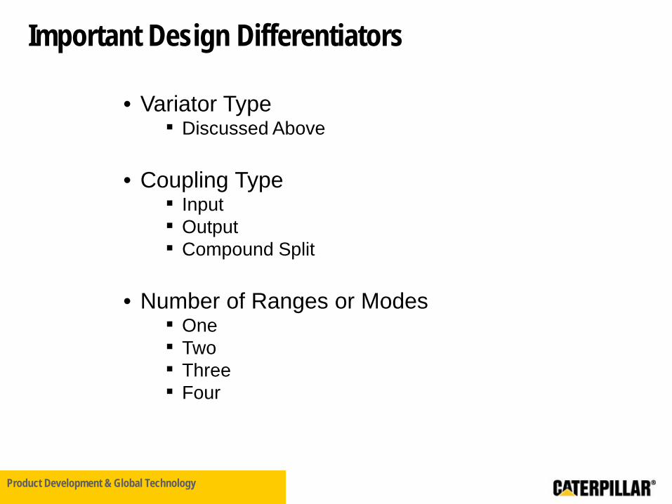
Important Design Differentiators
• Variator Type ▪ Discussed Above
• Coupling Type
▪ Input ▪ Output ▪ Compound Split
• Number of Ranges or Modes
▪ One ▪ Two ▪ Three ▪ Four

Product Development & Global Technology

Product Development & Global Technology
▪ Variable Pump ▪ Fixed Motor ▪ Integrated, Inline Package
▪ Used in ZF Designed cPower Shown @ 2010 Bauma ▪ Variable Pump ▪ Variable Motor ▪ Pump and Motor Displacements Linked ▪ Motor Displacement Decreases while Pump
Displacement Increases ▪ Integrated, U Package
Variator Examples

Product Development & Global Technology
Input Coupled / Output Split
In Out
Planetary Gear
System
Double Coupled / Unsplit
In Out
Planetary Gear
System
Output Coupled / Input Split
In Out
Planetary Gear
System
Uncoupled / Compound Split
In Out
Planetary Gear
System
Explaining the term “Coupled”
The Variator is Coupled to the Output The Variator is Coupled to the Input
Cat CVT JD 6000, 7000 IVT
S-Matic Graziano Fiat/Ag
ZF Eccom Rexroth HVT 2nd,3rd
914 ST125 1st
Rexroth HVT 1st
D6E D7E
795AC
Vario 8000 IVT 1st,3rd
ZF CP
Prius Dual Mode/AHSII/EP40 1st
8000 IVT 2nd,4th
ZF CP 2nd,3rd
Dual Mode/AHSII/EP40 2nd
Hyd
raul
ic
Varia
tors
El
ectr
ic
Varia
tors
Volt

Product Development & Global Technology
Engine Speed vs Ground Speedw Discrete Step Transmission
600800
100012001400
16001800
20002200
0 5 10 15 20 25Ground Speed mph
Engi
ne S
peed
rpm
Discrete Ratio Powertrain Schematic
Engine Transmission
Aux Loads
• Discrete Ratio Transmission – Several selectable gear ratios – Slipping clutch for launch
Transfer Gear And/or Axle Reductions
Wheel Or
Sprocket
Ground Speed 2
One Engine Speed Possible at
Ground Speed 2
Ground Speed 1
Two Engine Speeds Possible at Ground
Speed 1

Product Development & Global Technology
1000
1100
1200
1300
1400
1500
1600
1700
1800
1900
2000
2100
2200
0
10
20
30
40
50
60
70
80
90
100
110
120
130
140
150
160
170
180
190
200
210
220
230
Engine Speed rpm
Engi
ne G
ross
Pow
er k
W
Hypothetical Engine Fuel Rate Contoursg/min
800-900
700-800
600-700
500-600
400-500
300-400
200-300
100-200
0-100
Approximate Minimum Fuel Consumption
Ground Speed 1 Ground Speed 2

Product Development & Global Technology
Continuously Variable Ratio Powertrain Schematic
Engine Transmission
Aux Loads
• Continuously Variable Transmission – Ratio continuously managed for
performance and launch
Transfer Gear And/or Axle Reductions
Wheel Or
Sprocket
Engine Speed vs Ground Speed
600
8001000
12001400
1600
18002000
2200
0 5 10 15 20 25Ground Speed mph
Engi
ne S
peed
rpm
Functional Definition of CVT: Engine speed can be placed and maintained at the desired level regardless of ground speed.
Any Engine Speed Possible at Any Ground Speed
Product Development & Global Technology
END