An Introduction to Electrospinning and Nanofibers - Copy
396
description
an introduction to electrospinning
Transcript of An Introduction to Electrospinning and Nanofibers - Copy

An Introduction to
Electrospinningand Nanofibers

An Introduction to
Electrospinningand Nanofibers
Seeram Ramakrishna, Kazutoshi Fujihara,
Wee-Eong Teo.Teik-Cheng Lim & Zuwei Ma
National University of Singapore
YJ? World ScientificN E W J E R S E Y • L O N D O N • S I N G A P O R E • B E I J I N G • S H A N G H A I • H O N G K O N G • T A I P E I • C H E N N A I
Published by
World Scientific Publishing Co. Pte. Ltd.
5 Ton Tuck Link, Singapore 596224
USA office: 27 Warren Street, Suite 401-402, Hackensack, NJ 07601
UK office: 57 Shelton Street, Covent Garden, London WC2H 9HE
British Library Cataloguing-in-Publication DataA catalogue record for this book is available from the British Library.
AN INTRODUCTION TO ELECTROSPINNING AND NANOFIBERS
Copyright © 2005 by World Scientific Publishing Co. Pte. Ltd.
All rights reserved. This book, or parts thereof, may not be reproduced in any form or by any means,electronic or mechanical, including photocopying, recording or any information storage and retrievalsystem now known or to be invented, without written permission from the Publisher.
For photocopying of material in this volume, please pay a copying fee through the Copyright ClearanceCenter, Inc., 222 Rosewood Drive, Danvers, MA 01923, USA. In this case permission to photocopyis not required from the publisher.
ISBN 981-256-415-2ISBN 981-256-454-3 (pbk)
Printed in Singapore by World Scientific Printers (S) Pte Ltd
Foreword
Even though research and development related to the electrospinningprocess and the electrospun nanofibers has increased in recent years, theavailability of the corresponding literature is mainly confined to researchjournals. As a consequence, information on electrospinning process andelectrospun nanofibers is comprehensible only for the highly specializedreaders. The situation is further compounded as a result of differingapproaches and perspectives from various interdisciplinary backgrounds.In spite of the numerous groups throughout the world investigating onelectrospinning of nanofibers, the lack of introductory reading materialsin this field is felt.
The appearance of this book is timely in view of this rapidly expandingfield of science and technology. There exists a critical mass ofinformation in this area for a book to be written. In order to attain abalanced perspective, this book was written by a group of researchersfrom various backgrounds - mechanical and chemical engineering,materials science, chemistry.
The contents page shows that this book covers a wide spectrum, whichincludes the basic materials used for manufacturing nanofibers,processing techniques and parameters, various characterization methods,various ways to produce different types of nanofibers, the surfacemodification & functionalization, theoretical understanding andmodeling approaches, and finally the potential applications.
V
vi An Introduction to Electrospinning and Nanofibers
The book is intended for the use of practicing engineers and scientists, aswell as the students interested in electrospinning process and applicationsof the electrospun mats and nanofibers.
A.L. YarinTechnion -Israel Institute of Technology
Haifa
Contents
Foreword v
1. Introduction 11.1. Preface of Nanofibers 11.2. Nanotechnology and Nanofibers 31.3. Various Ways to Make Nanofibers 7
1.3.1. Drawing 101.3.2. Template Synthesis 121.3.3. Phase Separation 131.3.4. Self-Assembly 151.3.5. Electrospinning 15
1.4. Scope of This Book 182. Basics Relevant to Electrospinning 22
2.1. Material Classes 232.1.1. Polymers 23
2.1.1.1. Fundamental Classification of Polymer 242.1.1.2. Polymer Crystallinity 242.1.1.3. Polymer Molecular Weight 262.1.1.4. Glass Transition Temperature (Tg) 272.1.1.5. Synthetic Polymer 372.1.1.6. Natural Polymer 392.1.1.7. Copolymer and Polymer Blends 412.1.1.8. Electrospun Polymer Fiber 42
2.1.2. Composites 482.1.2.1 Composite Reinforcement 492.1.2.2 Polymer-Matrix Composite 50
2.1.3 Ceramics 512.1.3.1. Crystalline Structure 522.1.3.2. Amorphous Structure 532.1.3.3. Ceramic Biomaterials 542.1.3.4. Nanostructured Ceramics 552.1.3.5. Carbon 60
vii
viii An Introduction to Electrospinning and Nanofibers
2.2. Solution Property 632.2.1. Surface Tension 63
2.2.1.1. Effect of Temperature on Surface Tensi on 652.2.1.2. Surface Tension of Solvent Mixtures 65
2.2.2. Polymer Solubility 662.2.2.1. Effect of Polymer Structure on Solubility 662.2.2.2. Gibbs Free Energy 67
2.2.3. Viscosity 692.2.3.1. Solvent Effect on Intrinsic Viscosity 712.2.3.2. Temperature on Intrinsic Viscosity 722.2.3.3. Viscometry 73
2.2.4. Volatility (Evaporation) of Solution 782.2.5. Conductivity of Solution 80
2.3. Electrostatics 812.3.1. Electric Field 822.3.2. Potential Difference and Electric Field Representations 832.3.3. Surface Charge of Insulator 842.3.4. Field Ionization 85
2.4. Conclusions 863. Electrospinning Process 90
3.1. Polymer Solution Parameters 913.1.1. Molecular Weight and Solution Viscosity 913.1.2. Surface Tension 963.1.3. Solution Conductivity 983.1.4. Dielectric Effect of Solvent 101
3.2. Processing Conditions 1033.2.1. Voltage 1033.2.2. Feedrate 1063.2.3. Temperature 1083.2.4. Effect of Collector 1083.2.5. Diameter of Pipette Orifice / Needle I l l3.2.6. Distance Between Tip and Collector 112
3.3. Ambient Parameters 1133.3.1. Humidity 1143.3.2. Type of Atmosphere 1163.3.3. Pressure 116
3.4. Melt-Electrospinning 1173.5. Creation of Different Nanofibers 117
3.5.1. Porous Nanofibers 1183.5.2. Flattened or Ribbon-Like Fibers 1223.5.3. Branched Fibers 125
Contents ix
3.5.4. Helical Fibers 1263.5.5. Hollow Nanofibers 1273.5.6. Fiber With Different Compositions 130
3.6. Uniformity and Productivity of Nanofiber Webs 1303.6.1. Jet Stability 1313.6.2. Multiple-Spinning Setup 132
3.7. Mixed Electrospun Fiber Mesh 1333.8. Patterning 135
3.8.1. Cylinder Collector 1353.8.2. A Knife Edge Disk 1383.8.3. An Auxiliary Electrode/Electrical Field 1393.8.4. Parallel Conducting Collector 142
3.9. Fiber Yarn and Textile 1453.9.1. Hybrid Fiber Yarns 1463.9.2. Electrospun Fiber Yarn 1473.9.3. Twisted Fiber Yarn 148
3.10. Variations to Electrospinning 1493.10.1. Scanning Tip Electrospinning Source 1503.10.2. Nanofiber Interconnections Between Microscale Features.. 1513.10.3. Mass Production Through Needleless Electrospinning 152
3.11. Conclusions 1544. Modeling of the Electrospinning Process 155
4.0. Nomenclature 1554.1. Introduction 1574.2. Preliminaries 1584.3. Assumptions 161
4.3.1. Jet Representation 1614.3.2. Modeling Viscoelastic Behavior 1624.3.3. Coordinate System 1674.3.4. Liquid Incompressibility 168
4.4. Conservation Relations 1684.4.1. Conservation of Mass 1684.4.2. Conservation of Momentum 1704.4.3. Conservation of Charge 172
4.5. Consideration of Forces 1734.6. Instability 1744.7. Results 1794.8. Future Trends and Challenges 188
4.8.1. Jet Flow With Particles 1894.8.2. Core-Shell Flow 1894.8.3. Field-Assisted Flow 190
x An Introduction to Electrospinning and Nanofibers
4.8.4. Multi-Jet Flow 1904.8.5. Gas-Assisted Flow 190
4.9. Conclusions 1915. Characterization 192
5.1. Morphology 1935.1.1. Fiber Diameter 1935.1.2. Pore Size and Porosity 1995.1.3. Surface Contact Angle Measurement 2065.1.4. Others 209
5.2. Molecular Structure 2105.2.1. Crystalline Structure 2105.2.2. Organic Group Detection 2255.2.3. Others 229
5.3 Mechanical Property 2345.3.1. Single Nanofiber 2345.3.2. Nanofiber Yarn 2405.3.3. Nanofiber Membrane 241
5.4. Conclusions 2456. Functionalization of Polymer Nanofibers 247
6.1. Polymer Surface Modification 2476.1.1. Introduction 2476.1.2. Physical Coating or Blending 2486.1.3. Graft Copolymerization 250
6.1.3.1. Radiation-Induced Graft Copolymerization 2516.1.3.2. Plasma-Induced Graft Copolymerization 2536.1.3.3. Oxidization-Induced Graft Copolymerization 255
6.1.4. Plasma Treatment and Chemical Vapor Deposition 2566.1.5. Chemical Treatment 257
6.2. Functionalization of Nanofibers for Different Applications 2616.2.1. Introduction 2616.2.2. Functionalization of Nanofibers for Affinity Membrane
Application 2616.2.3. Functionalization of Nanofiber for Tissue Engineering
Scaffold Application 2666.2.4. Functionalization of Nanofibers for Sensor Application 2696.2.5. Functionalization of Nanofiber for Protective Cloth
Application 2716.2.6. Functionalization of Nanofibers for Other Applications 273
6.3. Conclusions 2747. Potential Applications 275
7.1. Introduction 2757.2. Affinity Membranes 279
Contents xi
7.3. Drug Release 2857.4. Tissue Scaffolds 2917.5. Wound Dressing 3077.6. Filter Media 3097.7. Chemical and Biological Protective Clothing 3117.8. Energy and Electrical Application 3207.9. Sensors 3267.10. Composite Reinforcement 3337.11. Conclusions 339
Appendix A Glossary of Terms 341Appendix B Useful Websites on Electrospinning and Nanofibers 350Bibliography 352Index 381

Chapter 1
Introduction
1.1. Preface of Nanofibers
It is essential in the beginning of this book to firstly define what ananofiber is. To do so, we split the term into two parts, namely "nano"and "fiber". As the latter term is more common, we begin by consideringthe latter from various professional viewpoints. Botanists identify thisterm with elongated, thick-walled cells that give strength and support toplant tissue. Anatomists understand "fibers" as any of the filamentsconstituting the extracelullar matrix of connective tissue, or any ofvarious elongated cells or threadlike structures, especially muscle fiber ornerve fiber. The textile industry views fibers as natural or syntheticfilament, such as cotton or nylon, capable of being spun into yarn, orsimply as material made of such filaments. Physiologists and biochemistsuse the term "fiber" to refer to coarse, indigestible plant matter,consisting primarily of polysaccharides such as cellulose, that wheneaten stimulates intestinal peristalsis. Historically, the term "fiber", or"fibre" in British English, comes from Latin "fibra". In this book wedefine a "fiber" from a geometrical standpoint - a slender, elongated,threadlike object or structure.
l
2 An Introduction to Electrospinning and Nanofibers
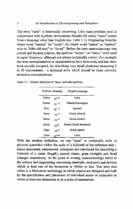
The term "nano" is historically interesting. Like many prefixes used inconjunction with Systeme International d'unites (SI units), "nano" comesfrom a language other than English (see Table 1.1). Originating from theGreek word "nannas" for "uncle", the Greek word "nanos" or "nannos"refer to "little old man" or "dwarf. Before the term nanotechnology wascoined and became popular, the prefixes "nanno-" or "nano-" were usedin equal frequency, although not always technically correct. For examplethe term nannoplanktons or nanoplanktons have been used, and has sincebeen socially accepted, for describing very small planktons measuring 2to 20 micrometers - a technical error which should be more correctlytermed as microplanktons.
Table 1.1. Modern definition of "nano" and other prefixes.
Prefixes Meaning Original language
Yokto JQ-24 Latin
Femto JQ-15 Danish Norwegian
Pico io~12 Spanish
Nano JQ-9 Greek (dwarf)
Micro JQ-6 Greek (small)
Hecto JQ+2 French Greek (hundred)
Giga JQ+9 Greek (giant)
Yotta in+24 Latin
With the modern definition, we use "nano" to technically refer tophysical quantities within the scale of a billionth of the reference unit -hence nanometer, nanosecond, nanogram and nanofarad for describing abillionth of a meter (length), second (time), gram (weight) and farad(charge) respectively. At the point of writing, nanotechnology refers tothe science and engineering concerning materials, structures and deviceswhich at least one of the dimension is lOOnm or less. This term alsorefers to a fabrication technology in which objects are designed and builtby the specification and placement of individual atoms or molecules orwhere at least one dimension is on a scale of nanometers.
Chapter I Introduction 3
At this juncture, we wish to point out that whilst the academiccommunity has somewhat agreed to the <100nm criterion as thebenchmark for the nanotechnology classification, the commercial sectorhas allowed broader flexibility - such as 300nm or even up to 500nm -which some academics would classify as sub-microtechnology. Theauthors are of the opinion that both benchmarks have their own merits.Whilst the imposition of a strict guideline is essential for maintainingsome form of standard, the loose definition would be beneficial for theindustry - for which the product quality and dimension is ultimatelydetermined by the consumers and not mere measurements. Havingpointed out the merit of the loose definition, the importance of the strictdefinition becomes evident in the light of the loose definition - a strictstandard inhibits the loose definition from getting out of hand.
Ever since the the term "nanotechnology" was coined by K. Eric Drexlerin his book "Engines of Creation", the field of nanotechnology has beena hot topic both in the academia and the industry. Although the positionalmanipulation of xenon atoms on a nickel substrate in 1990 (to spell thelogo of a very large computer company) was hailed by some as the "firstunequivocal" nanofabrication experiment, it should be borne in mind thatthe growth of nanowires and nanorods by vapor-liquid-solid method wasreported in the beginning of 1960s and the spontaneous growth ofnanowires and nanorods was in the 1950s. The scientific know-how ofgold nanoparticle synthesis was, in fact, performed by Faraday. Perhapsthe first nanotechnologists can be attributed to medieval stained-glassmakers who, by prescribing varying amount of gold particles, producedgold with colors other than gold color. Unbeknown to the medievalstained-glass makers, these tiny gold spheres, which absorbed andreflected sunlight in differing frequency, will forever be part of thehistory of size effects in nano-scale object.
1.2. Nanotechnology and Nanofibers
In this sub-chapter an attempt is made to classify nanofibers into one ormore sub-category of nanotechnology.
4 An Introduction to Electrospinning and Nanofibers
To do so we briefly review some common sub-fields of nanotechnologyitself. As far as "nanostructures" are concerned, one can view this asobjects or structures whereby at least one of its dimensions is withinnano-scale. A "nanoparticle" can be considered as a zero-dimensionalnano-element, which is the simplest form of nanostructure. It follows thata "nanotube" or a nanorod" is a one-dimensional nano-element fromwhich slightly more complex nanostructure can be constructed of.Following this train of thought, a "nanoplatelet" or a "nanodisk" is atwo-dimensional element which, along with its one-dimensionalcounterpart, are useful in the construction of nanodevices.
The difference between a nanostructure and a nanodevice can be viewedupon as the analogy between a building and a machine (whethermechanical, electrical or both). It goes without saying that as far as nano-scale is concerned, one should not pigeon-hole these nano-elements - foran element that is considered a structure can at times be used as asignificant part of a device. For example, the use of carbon nanotube asthe tip of an Atomic Force Microscope (AFM) would have it classified asa nanostructure. The same nanotube, however, can be used as a single-molecule circuit, or as part of a miniaturized electronic component,thereby appearing as a nanodevice. Hence the function, along with thestructure, is essential in classifiying which nanotechnology sub-area itbelongs to.
Whilst nanostructures clearly define the solids' overall dimensions, thesame cannot be said so for nanomaterials. In some instances ananomaterial refers to a nano-sized material while in other instances ananomaterial is a bulk material with nano-scaled structure. Nanocrystalsappear to be a misnomer. It is understood that a crystal is highlystructured and that the repetitive unit is indeed small enough. Hence ananocrystal refers to the size of the entire crystal itself being nano-sized,but not of the repetitive unit.
Chapter 1 Introduction 5
Nanophotonics refers to the study, research, development and/orapplications of nano-scale object that emit light and its correspondinglight. These objects are normaly quantum gots. Whilst the emission ofphoton is largest for bulk (3-dimensional), followed by quantum well (2-dimensional) and finally quantum dot (O-dimensional), the ranking isreversed in terms of efficiency.
Although the term nanomagnetics is self expanatory, we wish to view itin terms of highly miniaturized magnetic data storage materials with veryhigh memory. This can be attained by taking advantage of the electronspin for memory storage - hence the term "spin-electronics", which hassince been more popularly and more conveniently known as"spintronics".
In nanobioengineering, the novel properties at nano-scale are takenadvantage of for bioengineering applications. The many naturallyoccurring nanofibrous and nanoporous structure in the human bodyfurther adds to the impetus for research and development in this sub-area.Closely related to this is molecular functionalization whereby the surfaceof an object is modified by attaching certain molecules to enable desiredfunctions to be carried out - such as for sensing and/or filteringchemicals based on molecular affinity.
With the rapid growth of nanotechnology, nanomechanics is no longerthe narrow field it used to be. This field can be broadly categorized intothe molecular mechanics and the continuum mechanics approaches -which view objects as consisting of discrete many-body system andcontinuous media respectively. Whilst the former inherently includes thesize-effect, it is a requirement for the latter to factor in the influence ofincreasing surface-to-volume ratio, molecular reorientation and othernovelties as the size shrinks.
As with many other fields, nanotechnology includes nanoprocessing -novel materials processing techniques by which nano-scale structuresand devices are designed and constructed.
6 An Introduction to Electrospinning and Nanofibers
Depending upon the final size and shape, a nanostructure or nanodevicecan be produced by the top-down or the bottom up approach. The formerrefers to the act of removal or cutting down a bulk to the desired sizewhilst the latter takes on the philosophy of using fundamental buildingblocks - such as atoms and molecules - to build up nanostructures in thesame manner as one would towards lego sets. It is obvious that the top-down and the botton-up nanoprocessing methodologies are suitable forthe larger and to smaller ends respectively in the spectrum of nano-scaleconstruction. The effort of nanopatterning - or patterning at the nano-scale - would hence fall into nanoprocessing.
So where does all these descriptions point nanofibers to? It is obviousthat nanofibers would geometrically fall into the category of 1-dimensional nano-scale elements that includes nanotubes and nanorods.However, the flexible nature of nanofibers would align it along withother highly flexible nano-elements such as globular molecules (assumedas O-dimensional soft matter), as well as solid and liquid films of nano-thickness (2-dimensional). A nanofiber is a nanomaterial in view of itsdiameter, and can be considered a nanostructured material material iffilled with nanoparticles to form composite nanofibers.
Where application to bioengineering is concerned, such as the use ofnanofibrous network to tissue engineering scaffolds, these nanofibersplay significant roles in nanobioengineering [Lim and Ramakrishna(2005)]. The study on the nanofiber mechanical properties as a result ofmanufacturing techniques, constituent materials, processing parametersand other factors would fall into the category of nanomechanics. Indeed,while the primary classification of nanofibers is that of nanostructure ornanomaterial, other aspects of nanofibers such as its characteristics,modeling, application and processing would enable nanofibers topenetrate into many subfields of nanotechnology. Finally the processingtechniques of nanofibers are diverse, and include both the top-down andthe bottom-up approaches as we shall see in the next sub-chapter.
Chapter 1 Introduction 7
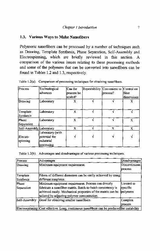
1.3. Various Ways to Make Nanofibers
Polymeric nanofibers can be processed by a number of techniques such
as Drawing, Template Synthesis, Phase Separation, Self-Assembly and
Electrospinning, which are briefly reviewed in this section. A
comparison of the various issues relating to these processing methods
and some of the polymers that can be converted into nanofibers can be
found in Tables 1.2 and 1.3, respectively.
Table 1.2(a). Comparison of processing techniques for obtaining nanofibers.
Process Technological Can the Repeatability Convenient to Control onadvances process be process? fiber
scaled? dimensionsDrawing Laboratory X V \ X
Template Laboratory X V V VSynthesisPhase Laboratory X V ^ XSeparationSelf-Assembly Laboratory X V X X
Laboratory (withElectro- potential for V V V Vspinning industrial
processing
Table 1.2(b). Advantages and disadvantages of various processing techniques.
Process Advantages DisadvantagesDrawing Minimum equipment requirement. Discontinuous
process
Template Fibers of different diameters can be easily achieved by usingSynthesis different templates.Phase Minimum equipment requirement. Process can directly Limited toSeparation fabricate a nanofiber matrix. Batch-to-batch consistency is specific
achieved easily. Mechanical properties of the matrix can be polymerstailored by adjusting polymer concentration.
Self-Assembly Good for obtaining smaller nanofibers. Complexprocess
Electrospinning Cost effective. Long, continuous nanofibers can be produced Jet instability
8 An Introduction to Electrospinning and Nanofibers
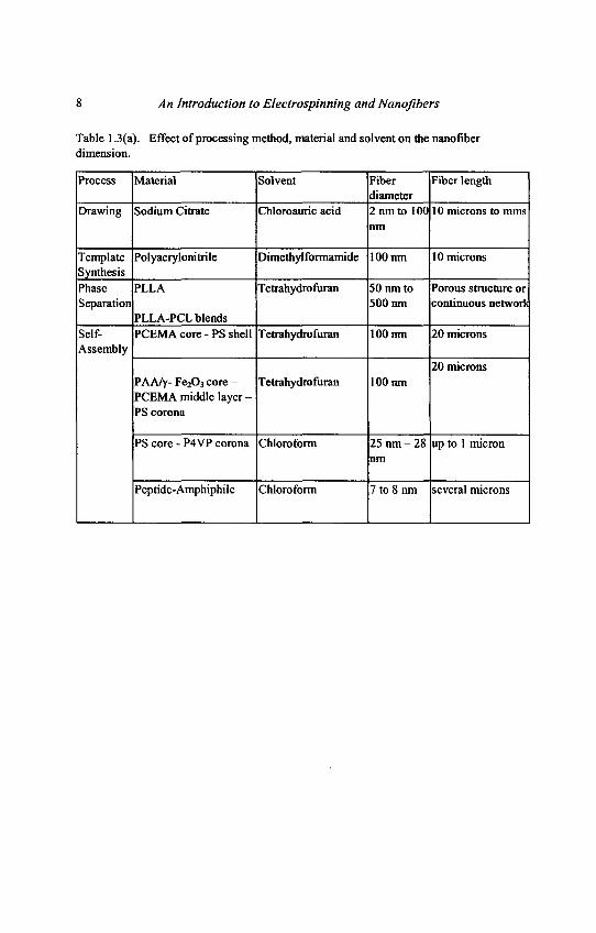
Table 1.3(a). Effect of processing method, material and solvent on the nanofiberdimension.
Process Material Solvent Fiber Fiber lengthdiameter
Drawing Sodium Citrate Chloroauric acid 2 run to 100 10 microns to mmsnm
Template Polyacrylonitrile Dimethylformamide 100 nm 10 micronsSynthesisPhase PLLA Tetrahydrofuran 50 nm to Porous structure orSeparation 500 nm continuous network
PLLA-PCL blendsSelf- PCEMA core - PS shell Tetrahydrofuran 100 nm 20 micronsAssembly
20 micronsPAA/y-Fe2O3 core - Tetrahydrofuran 100 nmPCEMA middle layer -PS corona
PS core - P4VP corona Chloroform 25 nm - 28 up to 1 micronnm
Peptide-Amphiphile Chloroform 7 to 8 nm several microns
Chapter 1 Introduction 9
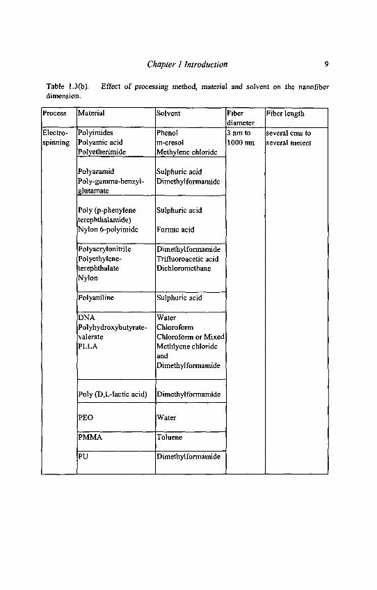
Table 1.3(b). Effect of processing method, material and solvent on the nanofiberdimension.
Process Material Solvent Fiber Fiber lengthdiameter
Electro- Polyimides Phenol 3 run to several cms tospinning Polyamic acid m-cresol 1000 run several meters
Polyetherimide Methylene chloride
Polyaramid Sulphuric acidPoly-gamma-benzyl- Dimethylformamideglutamate
Poly (p-phenylene Sulphuric acidterephthalamide)Nylon 6-polyimide Formic acid
Polyacrylonitrile DimethylformamidePolyethylene- Trifluoroacetic acidterephthalate DichloromethaneNylon
Polyaniline Sulphuric acid
DNA WaterPolyhydroxybutyrate- Chloroformvalerate Chloroform or MixedPLLA Methlyene chloride
andDimethylformamide
Poly (D,L-lactic acid) Dimethylformamide
PEO Water
PMMA Toluene
PU Dimethylformamide
10 An Introduction to Electrospinning and Nanofibers
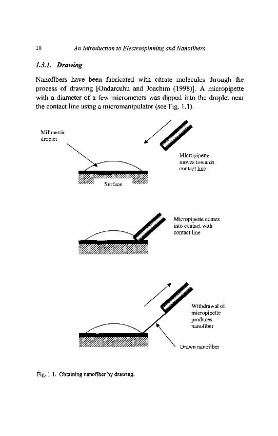
1.3.1. Drawing
Nanofibers have been fabricated with citrate molecules through theprocess of drawing [Ondarcuhu and Joachim (1998)]. A micropipettewith a diameter of a few micrometers was dipped into the droplet nearthe contact line using a micromanipulator (see Fig. 1.1).
Fig. 1.1. Obtaining nanofiber by drawing.
Chapter 1 Introduction 11
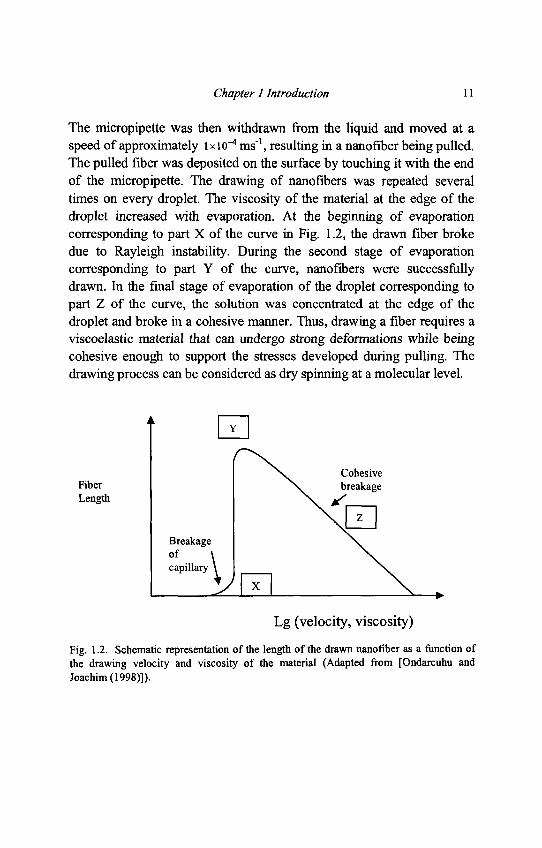
The micropipette was then withdrawn from the liquid and moved at aspeed of approximately 1 x KT4 ms"1, resulting in a nanofiber being pulled.The pulled fiber was deposited on the surface by touching it with the endof the micropipette. The drawing of nanofibers was repeated severaltimes on every droplet. The viscosity of the material at the edge of thedroplet increased with evaporation. At the beginning of evaporationcorresponding to part X of the curve in Fig. 1.2, the drawn fiber brokedue to Rayleigh instability. During the second stage of evaporationcorresponding to part Y of the curve, nanofibers were successfullydrawn. In the final stage of evaporation of the droplet corresponding topart Z of the curve, the solution was concentrated at the edge of thedroplet and broke in a cohesive manner. Thus, drawing a fiber requires aviscoelastic material that can undergo strong deformations while beingcohesive enough to support the stresses developed during pulling. Thedrawing process can be considered as dry spinning at a molecular level.
Fig. 1.2. Schematic representation of the length of the drawn nanofiber as a function ofthe drawing velocity and viscosity of the material (Adapted from [Ondarcuhu andJoachim (1998)]).
12 An Introduction to Electrospinning and Nanofibers
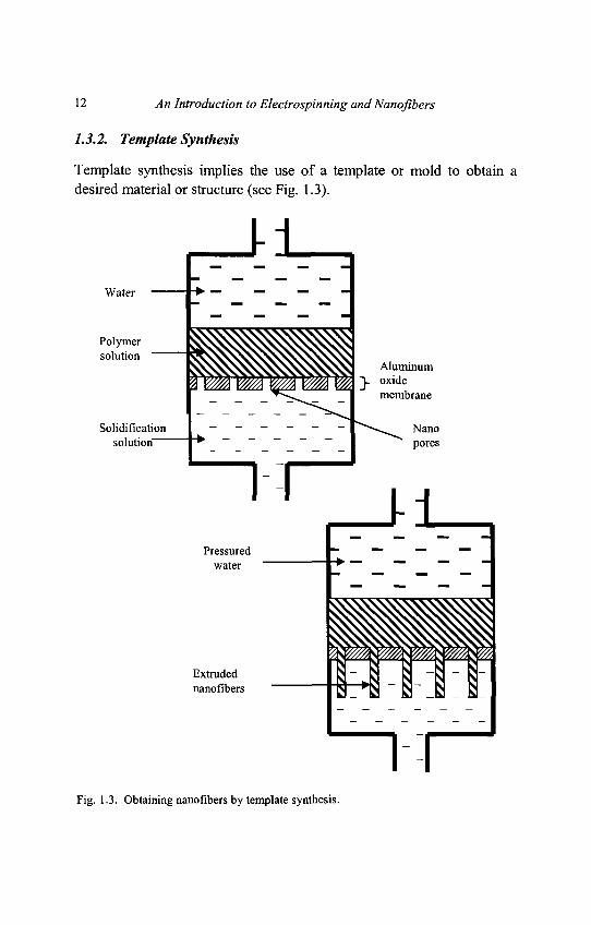
1.3.2. Template Synthesis
Template synthesis implies the use of a template or mold to obtain adesired material or structure (see Fig. 1.3).
Fig. 1.3. Obtaining nanofibers by template synthesis.
Chapter 1 Introduction 13
Hence the casting method and DNA replication can be considered astemplate-based synthesis. For the case of nanofiber creation by [Feng etal. (2002)], the template refers to a metal oxide membrane with through-thickness pores of nano-scale diameter. Under the application of waterpressure on one side and restrain from the porous membrane causesextrusion of the polymer which, upon coming into contact with asolidifying solution, gives rise to nanofibers whose diameters aredetermined by the pores.
1.3.3. Phase Separation
In phase separation, a polymer is firstly mixed with a solvent beforeundergoing gelation. The main mechanism in this process is - as thename suggests - the separation of phases due to physical incompatibility.One of the phase - which is that of the solvent - is then extracted,leaving behind the other remaining phase. A detailed procedure forproducing nanofibrous poly(L-lactic) acid (PLLA) has been described by[Ma and Zhang (1999)], which consists of 5 major steps: (i) polymerdissolution, (ii) gelation, (iii) solvent extraction, (iv) freezing and (v)freeze-drying, as follows:
(i) Tetrahydrofuran (THF) was added to PLLA for making asolution with the required concentration (1% w/v to 15%w/v). The solution was stirred at 60°C for two hours toproduce a homogeneous solution.
(ii) Two mililiters of the solution at 50°C was poured into aTeflon vial and then transferred to a refrigerator set togelation temperature (-18°C to 45°C) which was chosenbased on the PLLA concentration.Upon formation of the gel,it was kept at the gelation temperature for two hours,
(iii) The vial that contains the gel was immersed in distilledwater to allow solvent exchange and the water was changedthree times a day for two days.
(iv) The gel was then removed from water, blotted with filterpaper and then transferred to a freezer at -18°C and kept fortwo hours.
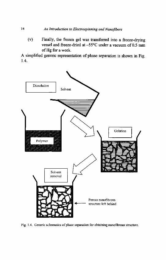
14 An Introduction to Electrospinning and Nanofibers
(v) Finally, the frozen gel was transferred into a freeze-dryingvessel and freeze-dried at -55°C under a vacuum of 0.5 mmof Hg for a week.
A simplified generic representation of phase separation is shown in Fig.1.4.
Fig. 1.4. Generic schematics of phase separation for obtaining nanofibrous structure.
Chapter 1 Introduction 15
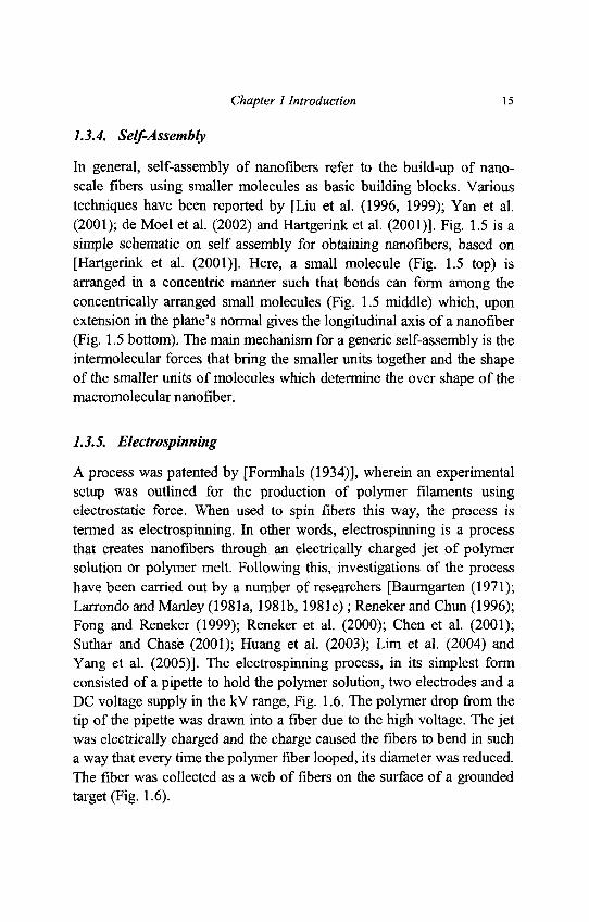
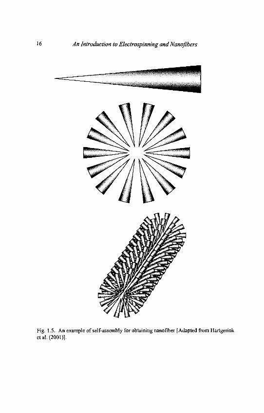
1.3.4. Self-Assembly
In general, self-assembly of nanofibers refer to the build-up of nano-scale fibers using smaller molecules as basic building blocks. Varioustechniques have been reported by [Liu et al. (1996, 1999); Yan et al.(2001); de Moel et al. (2002) and Hartgerink et al. (2001)]. Fig. 1.5 is asimple schematic on self assembly for obtaining nanofibers, based on[Hartgerink et al. (2001)]. Here, a small molecule (Fig. 1.5 top) isarranged in a concentric manner such that bonds can form among theconcentrically arranged small molecules (Fig. 1.5 middle) which, uponextension in the plane's normal gives the longitudinal axis of a nanofiber(Fig. 1.5 bottom). The main mechanism for a generic self-assembly is theintermolecular forces that bring the smaller units together and the shapeof the smaller units of molecules which determine the over shape of themacromolecular nanofiber.
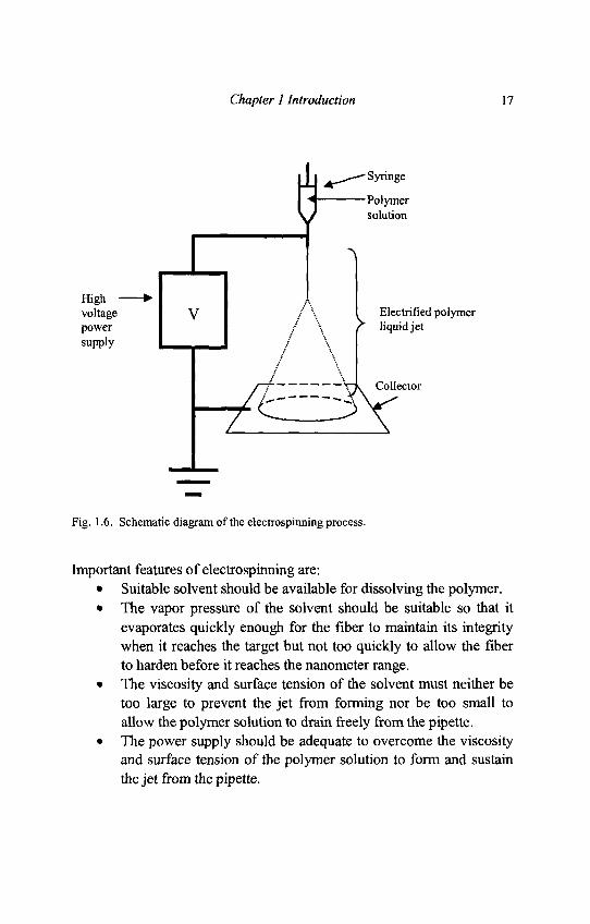
1.3.5. Electrospinning
A process was patented by [Formhals (1934)], wherein an experimentalsetup was outlined for the production of polymer filaments usingelectrostatic force. When used to spin fibers this way, the process istermed as electrospinning. In other words, electrospinning is a processthat creates nanofibers through an electrically charged jet of polymersolution or polymer melt. Following this, investigations of the processhave been carried out by a number of researchers [Baumgarten (1971);Larrondo and Manley (1981a, 1981b, 1981c) ; Reneker and Chun (1996);Fong and Reneker (1999); Reneker et al. (2000); Chen et al. (2001);Suthar and Chase (2001); Huang et al. (2003); Lim et al. (2004) andYang et al. (2005)]. The electrospinning process, in its simplest formconsisted of a pipette to hold the polymer solution, two electrodes and aDC voltage supply in the kV range, Fig. 1.6. The polymer drop from thetip of the pipette was drawn into a fiber due to the high voltage. The jetwas electrically charged and the charge caused the fibers to bend in sucha way that every time the polymer fiber looped, its diameter was reduced.The fiber was collected as a web of fibers on the surface of a groundedtarget (Fig. 1.6).
16 An Introduction to Electrospinning and Nanofibers
Fig. 1.5. An example of self-assembly for obtaining nanofiber [Adapted from Hartgerinket al. (2001)].
Chapter 1 Introduction 17
Fig. 1.6. Schematic diagram of the electrospinning process.
Important features of electrospinning are:• Suitable solvent should be available for dissolving the polymer.• The vapor pressure of the solvent should be suitable so that it
evaporates quickly enough for the fiber to maintain its integritywhen it reaches the target but not too quickly to allow the fiberto harden before it reaches the nanometer range.
• The viscosity and surface tension of the solvent must neither betoo large to prevent the jet from forming nor be too small toallow the polymer solution to drain freely from the pipette.
• The power supply should be adequate to overcome the viscosityand surface tension of the polymer solution to form and sustainthe jet from the pipette.
18 An Introduction to Electrospinning andNanofibers
• The gap between the pipette and grounded surface should not betoo small to create sparks between the electrodes but should belarge enough for the solvent to evaporate in time for the fibers toform.
1.4. Scope of This Book
As the book title implies, the aims of this book are to provide anintroduction to the electrospinning process for obtaining nanofibers andto interest the reader on the various potential applications of nanofibersas a result of their unique properties. This book includes both theexperimental techniques and theoretical understanding on theelectrospinning process.
This book can be split into two major blocks: Chapters 2 to 4 deal withelectrospinning while Chapters 5 to 7 focus on the electrospunnanofibers.
Chapter 2 covers some basic aspects of the electrospinning process byfirstly reviewing the various classes of materials such as polymers,composites and ceramics. Sub-topics on solution properties andelectrostatics, which are part and parcel of the electrospinning process,are covered in view of their inter-relatedness with the material classesand properties. This chapter serves as a fundamental starting point in ageneric manner.
The electrospinning process is covered in Chapter 3 whereby thepolymer solution parameters (such as viscosity, surface tension,conductivity, etc), electrospining process parameters (such as voltage,federate, tip-to-collector distance, etc) and ambient conditions (e.g.humidity) are discussed. In addition, issues on the uniformity,productivity, patterning and the creation of various types of nanofibers(such as ribbon-like, branched, helical, porous and tubular) are coveredin view of their importance in specific applications.
Chapter 1 Introduction 19
The purpose of this chapter is to follow up on the previous chapter bydelving into greater details of the materials and processing parameters,thereby giving the reader a qualitative picture on the factors thatinfluence the electrospinning process and the resultant nanofibers.
Chapter 4 elucidates the modeling of techniques of the electrospinningprocess for the purpose of introducing to the reader the more prominentmodeling techniques to date. The importance of this chapter can be seenin the quantitative aspects whereby the simulated results will aid theexperimentalists in obtaining the nanofiber of desired properties.
This chapter begins with the some assumptions normally adopted byeminent researchers in this field, and followed by the modeling ofviscoelastic behavior with particular emphasis of free liquid jets.Detailed derivation for the conservation laws are then introduced for thephysical quantities of mass, momentum and charge. This is followed bythe considering the types of forces normally acted on the free liquid jet,discussions on the instability and the perturbation assumptions to inducethe liquid bending instability. The result section shows some simulatedresults with emphasis on the effects of solidification and the instabilitywindows. This chapter ends with a short appreciation on the futuretrends.
The raw materials (solution) and the electrospinning process leads to thevarious types and properties of the nanofibers. Chapter 5 considers thetechniques for measuring the basic properties such as porosity andsurface contact angle. In addition, this chapter introduces the reader tothe characterization of the molecular structure (such as crystallinestructure, organic group detection, etc), mechanical properties (such asfor the case of single nanofiber, nanofiber yarn and nanofibrousmembrane).
20 An Introduction to Electrospinning and Nanofibers
The purpose of this chapter is to introduce to the reader the variousinstrumentation techniques for measuring and characterizing the obtainedelectrospun nanofibers. This chapter is important as the obtainedcharacterization results is useful for deciding the specific applications onthe basis of the nanofiber properties.
In order to enable the nanofibrous' surface to capture specific molecules(such as in the case of molecular filters and sensors), there is a need forthe surface to be molecularly modified to enable it to function in thedesired manner. This topic is addressed in Chapter 6 with particularemphasis on the case of nanofibers.
Various techniques for surface modification (such physical coating,blending, co-polymerization, chemical vapor deposition, chemicaltreatment, etc) are furnished. Thereafter, the functionalized nanofibersare discussed with regard to affinity membrane, tissue engineering,sensor, protective clothing and other applications.
The last chapter expounded on the many applications of nanofibers. hiview of the small fiber diameter and hence the nanofibrous structure withextremely large surface to volume ratio, this chapter discusses the currentapplications as well as potential for future applications in the fields ofaffinity membranes, filter media, tissue scaffolds, wound dressing, drugrelease, chemical & biological protective clothing, sensors, compositereinforcements, and energy & electrical applications.
A list of some useful websites that deal with nanofibers is given in theappendix which is correct at the point of writing. Throughout this book,the term nanofiber membrane refers a semi-transparent membraneobtained by electrospinning.
Chapter 1 Introduction 21
Whilst it is a membrane macroscopically, the membrane is a network ofnanofibrous structure. Hence the terms nanofiber membrane, nanofibermesh and nanofiber web are used interchangeably in order to reflect thediversity of viewpoints. These terms, as well as other technical terms, aredefined and explained in the glossary of terms for the benefit of the layreaders.
Chapter 2
Basics Relevant to Electrospinning
To understand electrospinning, one can look at the mechanism behindthe production of polymer fibers. Conventional fibers of large diameterinvolve the drawing of molten polymer out through a die. The resultantstretched polymer melt will dry to form individual strand of fiber.Similarly, electrospinning also involve the drawing of fluid, either in theform of molten polymer or polymer solution. However, unlikeconventional drawing method where there is an external mechanicalforce that pushes the molten polymer through a die, electrospinningmake use of charges that are applied to the fluid to provide a stretchingforce to a collector where there is a potential gradient. When a sufficienthigh voltage is applied, a jet of polymer solution will erupt from apolymer solution droplet. The polymer chain entanglements within thesolution will prevent the electrospinning jet from breaking up. Whilemolten polymer used in both conventional fiber production method andelectrospinning method cools and solidifies to yield fiber in theatmosphere, the electrospinning of polymer solution relies on theevaporation of the solvent for the polymer to solidify to form polymerfiber.
Since electrospinning is basically the drawing of a polymer fluid, thereare many different types of polymers and precursors that can beelectrospun to form fibers. The materials to be electrospun will dependon the applications. Materials such as polymers and polymer nanofibercomposites can be directly produced by electrospinning. Other materialssuch as ceramics and carbon nanotubes require post processing of theelectrospun fibers.
22
Chapter 2 Basics Relevant to Electrospinning 23
In this chapter, material properties, solution properties and electrostaticsare discussed. As each of the properties involved in electrospinning is ahuge science of its own, this chapter aims to give some basic informationrelevant to electrospinning. However, with growing interest and researchinto electrospinning, new fundamental properties may be discovered.
2.1. Material Classes
The materials and application of electrospun fibers are numerous,individual material properties must be considered depending on itsapplications. The electrospinning process may be modified so as to yieldelectrospun fiber with the desired morphology and properties. When usedas composite, the nanofibers can be made as a composite on its own or itcan be used as reinforcement in a matrix. In the production of ceramicfibers, post processes are required after the fibers are electrospun. Thus itis important to have a basic understanding of the different group ofmaterials before selecting the most appropriate electrospun fibers forspecific applications.
2.1.1. Polymers
Polymers consist of long chain of molecule with repeating units calledmonomers that are mostly covalently bonded to one another. An exampleof a polymer would be polyethylene which consist of repeating units of [-CH2CH2-]n. Such single unit is also known as monomer. The monomermust either have reactive functional groups such as amino groups (-NH2)or the have double bonds which may react under suitable conditions toprovide the covalent linkage between the repeating units. Such stronglinkages form the backbone of the polymer chain. It is common to findweak secondary bonds between the molecule chains which allow thechain to slide over one another. Polymers exhibit several properties thatare attractive for many applications. Most polymers are inexpensive asthey contain simple elements and they are relatively easy to synthesize.
24 An Introduction to Electrospinning and Nanqfibers
Polymers, with their low density can easily be molded into complexshape, which are strong and relatively inert. They have foundapplications in many areas such as clothing, food packaging, medicaldevices and aircraft. Natural polymers such as silks, collagen and agarosehave found usage in many tissue engineering applications.
2.1.1.1. Fundamental Classification of Polymer
A widely accepted classification of polymer is their responds to heat.There are basically two types of polymer under this classification,thermoplastic and thermoset. In thermoplastics, the linear polymers meltwhen heat is applied but solidifies when cooled. This heating and coolingcan be repeated many times without affecting the properties. Examplesof thermoplastic include polyethylene, polystyrene and vinyls. However,this would impose a limiting temperature for the material in use as astructural element above which the polymer may distort over time. Forthermosetting polymer, once an initial heat is applied, there iscrosslinking between polymer chains. Subsequent application of heatwould only degrade the polymer. Examples of thermoset includephenolics, urea and epoxies. This means that such polymer has muchhigher upper limiting temperature.
2.1.1.2. Polymer Crystallinity
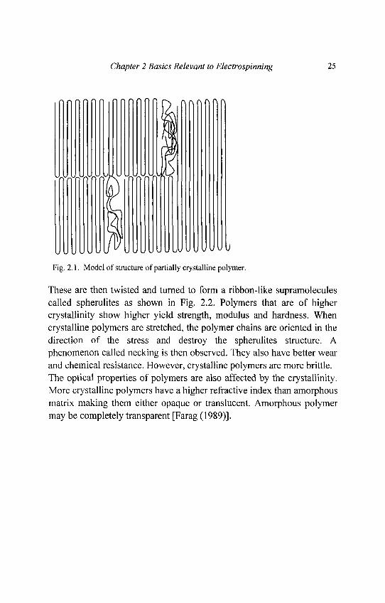
In bulk polymer, there are usually both regions of crystalline andamorphous parts as shown in Fig. 2.1. The ratio of the two regions woulddetermine the properties of the polymer. A polymer is said to beamorphous when the arrangement of the linear molecules is completelyrandom. A crystalline polymer has its linear adjacent linear chains arealigned. The more commonly accepted theory for crystalline polymer isthe folded chain theory. The polymer chains are first folded and stackedon top of one another held together by amorphous tie-molecules to fromcrystallites.
Chapter 2 Basics Relevant to Electrospinning 25
Fig. 2.1. Model of structure of partially crystalline polymer.
These are then twisted and turned to form a ribbon-like supramoleculescalled spherulites as shown in Fig. 2.2. Polymers that are of highercrystallinity show higher yield strength, modulus and hardness. Whencrystalline polymers are stretched, the polymer chains are oriented in thedirection of the stress and destroy the spherulites structure. Aphenomenon called necking is then observed. They also have better wearand chemical resistance. However, crystalline polymers are more brittle.The optical properties of polymers are also affected by the crystallinity.More crystalline polymers have a higher refractive index than amorphousmatrix making them either opaque or translucent. Amorphous polymermay be completely transparent [Farag (1989)].
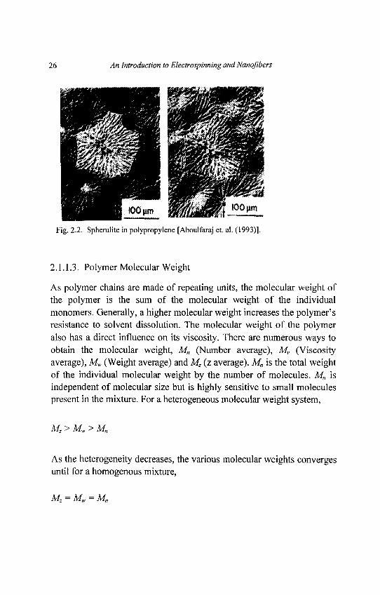
26 An Introduction to Electrospinning and Nanofibers
Fig. 2.2. Spherulite in polypropylene [Aboulfaraj et. al. (1993)].
2.1.1.3. Polymer Molecular Weight
As polymer chains are made of repeating units, the molecular weight ofthe polymer is the sum of the molecular weight of the individualmonomers. Generally, a higher molecular weight increases the polymer'sresistance to solvent dissolution. The molecular weight of the polymeralso has a direct influence on its viscosity. There are numerous ways toobtain the molecular weight, Mn (Number average), Mv (Viscosityaverage), Mw (Weight average) and Mz (z average). Mn is the total weightof the individual molecular weight by the number of molecules. Mn isindependent of molecular size but is highly sensitive to small moleculespresent in the mixture. For a heterogeneous molecular weight system,
MZ>MW> Mn
As the heterogeneity decreases, the various molecular weights convergesuntil for a homogenous mixture,
MZ = M W = Mn
Chapter 2 Basics Relevant to Electrospinning 27
2.1.1.4. Glass Transition Temperature (Tg)
The glass transition temperature is a very important property ofpolymers. This temperature defines the mobility state of the polymermolecules. Below its Tg, the amorphous polymer is brittle as themolecules are frozen but above Tg, the polymer is ductile and themolecular chains have sufficient thermal energy to slide. This causes theelastic modulus of amorphous polymers to decrease by several orders ofmagnitude at temperature above Tg. It is important to note that themechanical behavior of the polymer at temperature above Tg is affectedby the loading rate. Tg affects the mobility of polymer molecules,however, the motion of the molecular chain is not instantaneous. Forslow loading rate, the molecular chain have time to move at temperaturenear Tg but if the loading rate is fast, there may not be enough time forthe molecular chain to move thus increasing the effective Tg.
At temperature below Tg, it can be said that the relaxation time of themolecule is too long for equilibrium to occur under the slowest ofexperimental duration. When the temperature is at Tg, the moleculeswithin the polymer bulk move as a temperature-dependent"coorperatively rearranging" region. The size of this "coorperativelyrearranging" region is dependent on the configuration restrictions due toamorphous packing [Adam and Gibbs (1965)]. Molecular dynamicsimulation of a polymer melt has shown that there is an increasingclustering of mobile monomer unit as the temperature decreases to acritical temperature. When measuring the Tg, it is important to note thatthermal treatment of the sample, including heating and/or cooling rateduring measurement will affect the value obtained. Thus the measuringcondition must be noted when making comparison between differentexperiments.
In the study of thin polymer films, the glass transition temperature wasfound to found to be lower than the bulk [Ellison et. al. (2003)] and forPolystyrene, is given by the empirical relation,
28 An Introduction to Electrospinning and Nanofibers
( V"T -T 1 - — ("2 1")
where Tg:Mk is the bulk Tg for Polystyreneh is the thickness of the filma = 32Aand<5=1.8
Experiments have shown that in a polymer film, the mobility of thepolymer molecules near its surface is higher than molecules at the bulkdue to the substantially reduced Tg at the surface layer. However, thebulk dynamics beneath the surface area can slow down the mobility atthe surface leading to a higher surface Tg. When the film thickness isreduced sufficiently (about 14nm), the Tg at the surface is the same as theTg of the bulk [Ellison et. al. (2003)]. From the studies polymer film, itcan be seen that Tg is affected by the surface mobility. For a nanofiber,with the surface area larger than film, it has been experimentally shownto exhibit a lower Tg than cast film [Zong et. al. (2002)].
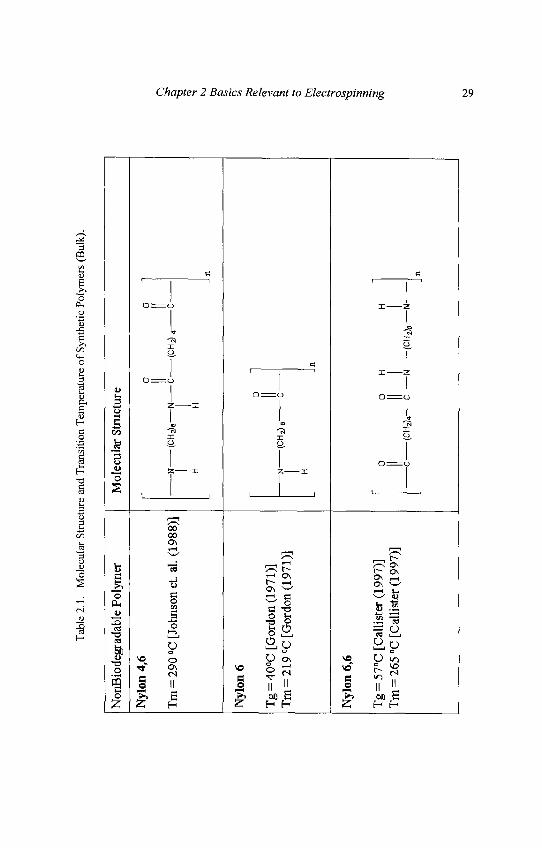
There are many factors that affect bulk Tg. Polymers with more free-volume allows easier movement of molecular chain thus lowering the Tg.Stronger secondary bonds such as H bonds would increase the Tg. Withgreater the chain length, there are more entanglements within thepolymer structure thus increasing the Tg. Table 2.1 shows the Tg, meltingpoint and the molecular structure of some common synthetic polymers.
Tab
le 2
.1.
Mol
ecul
ar S
truct
ure
and
Tra
nsiti
on T
empe
ratu
re o
f Sy
nthe
tic P
olym
ers
(Bul
k).
Non
Bio
degr
adab
le P
olym
er
Nyl
on 4
,6
Tm
= 2
90 °
C [J
ohns
on e
t. al
. (19
88)]
Nyl
on 6
Tg
= 4
0°C
[G
ordo
n (1
971)
]T
m =
219
°C
[Gor
don
(197
1)]
Nyl
on 6
,6
Tg
= 5
7°C
[C
allis
ter
(199
7)]
Tm
= 2
65 G
C [C
allis
ter
(199
7)]
Mol
ecul
ar S
truc
ture
0 0
II II
N
( CH
^e—
N
C
(CH
2J4
C
H
H
0
N
( CH
J B
C
H
n
n
0 O
H
H
C
(CH
2)4
C
N
(CH
2)e
Nn
Chapter 2 Basics Relevant to Electrospinning 29
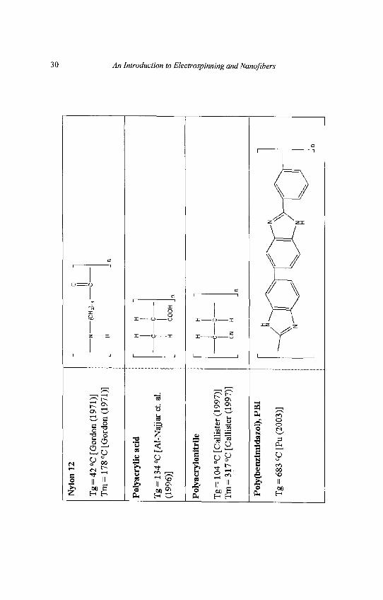
Nyl
on 1
2
Tg
= 4
2 °C
[Gor
don
(197
1)]
Tm
= 1
78 °C
[Gor
don
(197
1)]
-N
(CH
2) r
H
Pol
yacr
ylic
aci
d
Tg
= 1
34 °C
[A
l-N
ajja
r et
. al.
(199
6)]
H
H
•C
C
H
CO
OH
Pol
yacr
ylon
itrile
Tg
= 1
04 °C
[Cal
liste
r (1
997)
]T
tn =
317
°C [
Cal
liste
r (1
997)
]
H
H
- C
C
CN
H
Poly
(ben
zira
idaz
ol),
PB
I
Tg
= 6
83 Q
C[P
u (2
003)
]\
30 An Introduction to Electrospinning and Nanofibers
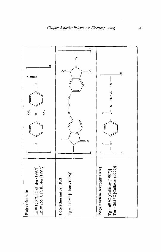
Pol
ycar
bona
te
Tg
= 1
50 D
C [C
allis
ter
(199
7)]
Tm
= 2
65 °
C [
Cal
liste
r (1
997)
]
Pol
y(et
heri
mid
e),
PE
I
Tg
= 2
19 °
C [C
hun
(199
6)]
Pol
y(et
hyle
ne t
erep
htha
late
)
Tg
= 6
9 °C
[C
alli
ster
(19
97)]
Tm
= 2
65 °
C [
Cal
list
er (
1997
)]
.0
R,
0.
N
R2
C
0 (C
H2)
2 0
-
Chapter 2 Basics Relevant to Electrospinning 31
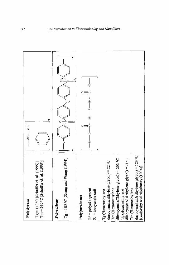
Pol
ysty
rene
Tg
= 1
10 °
C [
Scha
ffer
et.
al.
(199
9)]
Tm
= 2
40 °
C [S
chaf
lfer
et.
al.
(199
9)]
Pol
ysul
fone
Tg
= 1
85 °
C [
Zha
ng a
nd W
ang
(199
4)]
Pol
y(ur
e th
ane)
R'
= p
olyo
l se
gmen
tR
= i
socy
anat
e un
it
Tg
(Hex
amet
hyle
nedi
isoc
yana
te/E
thyl
ene
glyc
ol)
= 2
2 °C
Tm
(H
exam
ethy
lene
diis
ocya
nate
/Eth
ylen
e gl
ycol
) =
203
°C
Tg
(Hex
amet
hyle
nedi
isoc
yana
te/D
ieth
ylen
e gl
ycol
) =
-1
°CT
m (
Hex
amet
hyle
nedi
isoc
yana
te/D
ieth
ylen
e gl
ycol
) =
123
°C
[God
ovsk
y an
d S
loni
msk
y (1
974)
]
CH — it—
CH
2
]n
0 C
H3
0 0
R1
0 C
NH
R
NH
C
0
n
n
32 An Introduction to Electrospinning and Nanoflbers
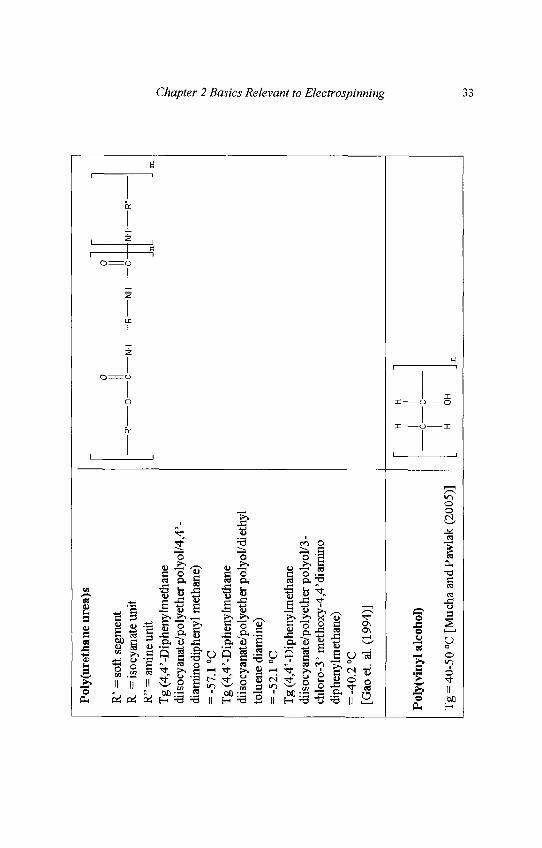
Pol
y(ur
etha
ne u
rea)
s
R' =
sof
t se
gmen
tR
= is
ocya
nate
uni
tR
" =
am
ine
unit
Tg
(4,4
'-Dip
heny
lmet
hane
diis
ocya
nate
/pol
yeth
er p
olyo
l/4,
4'-
diam
inod
iphe
nyl
met
hane
)=
-57
.1 °
CT
g (4
,4'-D
iphe
nylm
etha
nedi
isoc
yana
te/p
olye
ther
pol
yol/d
i eth
ylto
luen
e di
amin
e)=
-52
.1 °
CT
g (4
,4'-D
iphe
nylm
etha
nedi
isoc
yana
te/p
olye
ther
pol
yol/
3-ch
loro
-3'
met
hoxy
-4,4
'dia
min
odi
phen
ylm
etha
ne)
= -
40.2
°C[G
aoet
. al
. (19
94)]
Pol
y(vi
nyl
alco
hol)
Tg
= 4
0-50
°C
[Muc
ha a
nd P
awla
k (2
005)
]
0 0
||R1
0 C
N
H
R
NH
C
- n
NH
R"
H H
c h
ci
C)H
n
m
i to s' in of
lee,
I %.
SuiuuChapter 2 Basics Relevant to Electrospinning 33
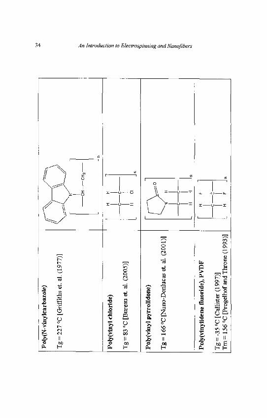
P ol
y(N
-vin
ylc a
r b az
ole)
Tg
= 2
27 °
C [
Gri
ffith
s et
. al.
(197
7)]
Pol
y(vi
nyl
chlo
ride
)
Tg
= 8
3 °C
[Bur
eau
et. a
l. (2
005)
]
Pol
y(vi
nyl
pyrr
olid
one)
Tg
= 1
66 °
C [N
uno-
Don
luca
s et
. al.
(200
1)]
Pol
y(vi
nylid
ene
fluo
ride
), P
VD
F
Tg
= -
35 °
C [
Cal
liste
r (1
997)
]T
m=
156
°C
[Pr
ogel
hof
and
Thr
one
(199
3)]
H
H
C
C-
H
Cl
N
H
C
C-
H
H
H
F
-C
C-
H
F
34 An Introduction to Electrospinning and Nanofibers
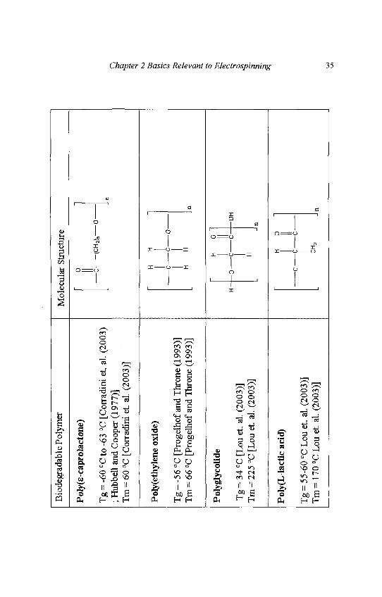
Bio
degr
adab
le P
olym
er
Pol
y(E
-cap
rola
cton
e)
Tg
= -
60 C
C to
-63
°C
[C
orra
dini
et.
al.
(200
3); H
ubbe
ll an
d C
oope
r (1
977)
]T
m =
60
°C [
Cor
radi
ni e
t. al
. (2
003)
]
Pol
y(et
hyle
ne o
xide
)
Tg
= -
56 °
C [
Prog
elho
f an
d T
hron
e (1
993)
]T
m =
66
°C [
Prog
elho
f an
d T
hron
e (1
993)
]
Pol
ygly
colid
e
Tg
= 3
4 CC
[Lou
et.
al.
(200
3)]
Tm
= 2
25 °
C [L
ou e
t. al
. (2
003)
]
Pol
y(L
-Iac
tic
acid
)
Tg
= 5
5-60
°C
Lou
et.
al. (
2003
)]T
m=
170
°C
Lou
et.
al.
(200
3)]
Mol
ecul
ar S
truc
ture
0 II c— H C H
H-
-0
< t
o —
(CH
2)S
O
H
- C
O
H
i 0
'
:—c-
H
n
n
- OH
n
H
0
-C
C
CH
3n
Chapter 2 Basics Relevant to Electrospinning 35
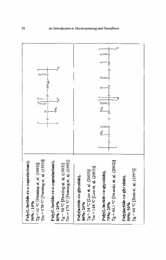
Pol
y(L
-lac
tide
-co-
E-c
apro
lact
one)
,90
% :
10
%T
g =
41
°C [
Penn
ing
et.
al.
(199
3)]
Tm
= 1
78 °
C [
Penn
ing
et.
al. (
1993
)]
Pol
y(L
-lac
tide
-co-
E-c
apro
lact
one)
,80
% :
20%
Tg
= 3
8 °C
[Pe
nnin
g et
. al
. (1
993)
]T
m =
174
°C
[P
enni
ng e
t. al
. (1
993)
]
CH
,
-0
(CH
2)5
C-
Pol
y(la
ctid
e-co
-gly
colid
e),
80%
: 20
%T
g =
54
°C [
Loo
et.
al.
(200
5)]
Tm
= 1
44 °
C [
Loo
et.
al.
(200
5)]
Pol
y(L
-lac
tide
-co-
glyc
olid
e),
75%
: 25
%T
g =
46.
1 °C
[Iw
asak
i et
. al.
(200
2)]
Pol
y(la
ctid
e-co
-gly
coli
de),
50%
: 50
%T
g =
44
°C [
Ibim
et.
al.
(199
7)]
CH
, 0
-O—
CH
-
CH
3 O
-0—
CH
--C
H
C
O—
CH
-
36 An Introduction to Electrospinning and Nanoflbers
Chapter 2 Basics Relevant to Electrospinning 37
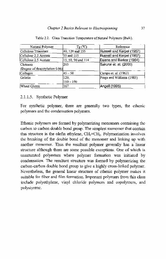
Table 2.2. Glass Transition Temperature of Natural Polymers (Bulk).
Natural Polymer Tg (°C) ReferenceCellulose Triacetate 40, 120 and 155 Russell and Kerpel (1957)Cellulose 2.2 Acetate 55 and 115 Russell and Kerpel (1957)Cellulose 2.5 Acetate 15,50, 90 and 114 Daane and Barker (1964)Chitosan 203 Sakurai et. al. (2000)(Degree of deacetylation 0.96)Collagen 45 - 50 Campo et. al. (1963)Gelatin 120, Fragaand Williams (1985)
180-190Wheat Gluten [l67 [Angell (1995) ~
2.1.1.5. Synthetic Polymer
For synthetic polymer, there are generally two types, the ethenicpolymers and the condensation polymers.
Ethenic polymers are formed by polymerizing monomers containing thecarbon to carbon double bond group. The simplest monomer that containthis structure is the olefin ethylene, CH2=CH2. Polymerization involvesthe breaking of the double bond of the monomer and linking up withanother monomer. Thus the resultant polymer generally has a linearstructure although there are some possible exceptions. One of which isunsaturated polyesters where polymer formation was initiated bycondensation. The resultant structure was formed by polymerizing thecarbon-carbon double bond group to give a highly cross-linked polymer.Nevertheless, the general linear structure of ethenic polymer makes itsuitable for fiber and film formation. Important polymers from this classinclude polyethylene, vinyl chloride polymers and copolymers, andpolystyrene.
38 An Introduction to Electrospinning andNanofibers
Amorphous polystyrene is one of the most useful plastic due to itsrigidity, low cost and excellent insulating properties. Although typicalapplications for polystyrenes include containers, house wares andfurniture parts, electrospun polystyrene fibers have potential applicationsin filter membranes and protective clothing. In its fiber form polystyrenehave a certain degree of flexibility. Electrospun polystyrene had shownseveral interesting morphologies such as beads and pores on the surfaceof the polymer [Casper et. al. (2004)].
For Condensation polymers, the monomers have at least two functionalgroups such as alcohol, amine or carboxylic acid group instead of acarbon-carbon double bond group. In condensation reaction, two unitsoften not of the same monomer structure reacts to form a polymer at thesame time releasing a small molecule such as H2O. The reaction is slowand the growth in molecular weight is gradual.
ExamplesPolyamides = carboxylic + aminePolyesters = carboxylic acid + alcohol
However, not all condensation polymerization involves the liberation ofsmall molecules. In this case, active hydrogen is transferred from onemolecule to the next instead. A typical example is the polymerization ofdialcohol and diisoyanate monomers to formpolyurethane.
In electrospinning, the sub-micron dimension of electrospun fibersresembles that of natural extra-cellular matrix. Thus it is not surprisingthat there are great interests in the use of electrospun fibers in the area ofbioengineering. One of the most frequently used synthetic polymers fortissue scaffolds are the biodegradable aliphatic polyesters. Thesedegradable polyesters are derived from three monomers, namely, lactide,glycolide and caprolactone. Hydrolytic attack of the ester bond withinthe polymer is responsible for its degradation [Griffith (2000)]. Poly-L-lactic acid for example is able to degrade to lactic acid, which is a normalintermediate of carbohydrate metabolism in man.
Chapter 2 Basics Relevant to Electrospinning 39
Polyurethanes are one of the most widely used polymers in biomedicalapplications especially those in contact with blood. This is due to theinherent, relative nonthrombogenicity of their surfaces and easysynthesis to different forms. Current applications include catheters, bloodbags and artificial heart systems. Electrospun polyurethane fibers haveshown great promises in the area of wound healing application. Whileprevious use of polyurethane occlusive dressings on the healing ofwound has the problem of significant fluid accumulation after a few daysof use, nanofibrous polyurethane membrane prepared by electrospinningpromoted fluid drainage. This is due to the high porosity of thenanofibrous membrane which also allows excellent oxygen permeability[Khilet. al. (2003)].
2.1.1.6. Natural Polymer
One of the greatest potential in electrospun fiber is in the area ofbioengineering. For many biomedical applications, the materials usedhave to be biocompatible, thus natural polymers have a distinctadvantage over synthetic materials. Since most natural polymer can bedegraded by naturally occurring enzymes, it can be used in applicationswhere temporary implants are desired or in drug release. It is alsopossible to control the degradation rate of the implanted polymer bychemical cross-linking or other chemical modifications thus allowinggreater versatility in the design of the implant [Atala and Lanza (2002)].Most polymers that have been electrospun are proteins andpolysaccharides.
Proteins that have been electrospun include collagen [Matthews et. al.(2002)], gelatin [Huang et. al. (2004)], fibrinogen [Wnek et. al. (2003)]and silk [Jin et. al. (2002); Ohgo et. al. (2003)]. One of the mostcommonly used natural polymers used is collagen. Collagens arenaturally found in connective tissues where they provide mechanicalsupport. There are at least ten different forms of collagens and they aredominant in specific tissue.
40 An Introduction to Electrospinning and Nanoflbers
However, all the collagens share the fundamental triple helix structure.As collagen exists naturally in fiber form, electrospun collagen fibers areable to mimic extracellular matrix in the body. In vitro studies had shownthat cells respond positively to tissue scaffold made of electrospuncollagen fibers. Generally, collagen is relatively strong and form stablefibers especially after cross-linking. However, till date, only Type I, IIand III collagen had been successfully electrospun [Matthews et. al.(2002)] together with their blends [Fertala et. al. (2001)]. The cost ofcollagen makes it expensive to yield thick fiber mesh fromelectrospinning. A cheaper alternative to collagen would be gelatinwhich can also be electrospun [Huang et. al. (2004)]. Another proteinthat is electrospun for use in tissue engineering is fibrinogen. As thisprotein plays a key role in blood clotting and wound healing, electrospunfibrinogen has been explored for possible usage in wound dressings[Wnek et. al. (2003)].
Proteins such as natural silk fiber have outstanding mechanicalproperties. This makes it an interesting candidate for application inbiomedical field where mechanical property is important. It is possible toelectrospin silk to obtain fibers with average diameter less than 500nm[Ohgo et. al. (2003)]. Electrospun fibers from silk fibroin were found topromote cell adhesion and proliferation [Min et. al. (2004)]. Silk fibroinitself has several advantages biological properties such as goodbiocompatibility, good oxygen and water vapor permeability,biodegradability and minimal inflammatory reaction [Sakabe et. al.(1989)]. The high surface area to volume ratio of the electrospun fiberalso encourages cell attachment, growth and proliferation.
A few polysaccharides and its modified form have been electrospun.Cellulose is a major constituent of nearly all form of plant matters, thusmaking it one of the most widely distributed and available raw materials.It is possible to modify the structure of the cellulose by reaction with thehydroxyl group or degradation of the cellulose chain. Cellulose acetate(CA) is one of the most commonly used materials for applications inwhere semi-permeable membranes are required such as dialysis, ultra-filtration and reverse osmosis.
Chapter 2 Basics Relevant to Electrospinning 41
CA can be electrospun and subsequent deacetylation of the fiber yieldpure cellulose fibers [Son et. al. (2004c); Liu and Hsieh (2002)]. Suchfine cellulose fibers have high surface area to volume ratio and the fiberstructure is thought to be much less ordered than its native or regeneratedcellulose. These make them highly desirable for surface-supportedreactions due to the accessibility if the hydroxyl group. Cellulose fiberspreviously electrospun from cellulose acetate had been methacrylated toform a unique fiber mesh that has a hydrophobic surface with ahydrophilic cellulose core [Liu and Hsieh (2003)].
Hyaluronic acid (HA) is another naturally occurring polysaccharidecommonly found in the specialized tissues such as synovial fluid, dermisand cartilage. This molecule plays an important role among theinterstitial proteins of the extra-cellular matrix providing importantbiological and mechanical functions. The chemical structure of HAconsists of D-glucuronic acid and N-acetylglucosamine arranged as arepeating disaccharide chain that contains as many as 30,000 or morerepeating disaccharide units [Laurent (1998)].
Due to its unique rheological properties and biocompatibility, HA hasbeen used extensively in many biomedical applications such asophthalmology, medical implants and drug delivery. Electrospinning HAwould yield HA membrane made out of sub-micron fibers [Um et. al.(2004)]. The high-surface area to volume ratio of the membrane wouldmake it attractive in applications such as tissue scaffolds, wounddressings and artificial blood vessels.
2.1.1.7. Copolymer and Polymer Blends
Sometimes, it is beneficial to obtain a structure that shows the propertiesof two or more polymers. This can be achieved either throughpolymerization of two different homopolymers to form a copolymer orby physical mixing of two or more polymers to form a blend. Incopolymers, the covalent bonding between the mers is very strong. Theindividual mers cannot be separated without breaking the copolymerchain.
42 An Introduction to Electrospinning and Nanofibers
There are generally two types of copolymers, random copolymers andblock copolymers. In random copolymers, there is no sequence in thedistribution between the two types of homopolymers. Thus the randomcopolymer exhibit properties that is intermediate to those ofcorresponding homopolymers. In block copolymers, the repeatinghomopolymers exist in long sequence within the polymer chain. Theblock copolymer may show property characteristics of each of theconstituent homopolymer.
In blending, the polymers tend to separate into two or more distinctphases due to incompatibility. To improve compatibility and miscibility,interactive functional groups are introduced to the polymers so that thepolymer chains would form stronger Hydrogen-bonding with theadvantage of improving the strength of the blend. Common functionalgroups include carboxylic and sulfonate groups. However, as there are nochemical reactions involved in polymer blending, the links between thedifferent polymers are not strong and leaching of one of the polymersmay occur, when submerged in a solvent.
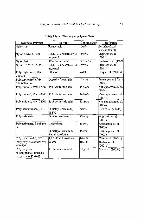
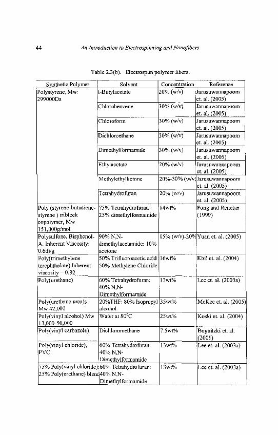
2.1.1.8. Electrospun Polymer Fiber
Till date, there are many polymers that have been electrospun includingcustom made polymers. Listed in Table 2.3(a) to Table 2.3(a) are themore commonly used non-biodegradable synthetic polymers with thecorresponding solvent and concentration used that is able to yield fiberswithout beads.
Chapter 2 Basics Relevant to Electrospinning 43
Table 2.3(a). Electrospun polymer fibers.
Synthetic Polymer Solvent Concentration ReferenceNylon 4,6 Formic acid 10wt% Bergshoefand
Vancso(1999)Nylon 6 Mw 43,300 1,1,1,3,3,3 hexafluoro-2- 15wt% Stephens et. al.
propanol (2004)Nylon 6,6 96% Formic acid 12.1 wt% Buchko et. al. (1999;Nylon 12 Mw, 32,000 1,1,1,3,3,3 hexafluoro-2- 15wt% Stephens et. al.
propanol (2004)Polyacrylic acid, Mw: Ethanol 6wt% Ding et. al. (2004b)250000Polyacrylonitrile, Mv Dimethylformamide 15wt% Fennessey and Farris114,000g/mol (2004)Polyamide-6, Mw: 17000 85% v/v formic acid 34%w/v Mit-uppatham et. al.
(2004)Polyamide-6, Mw: 20000 85% v/v formic acid 34%w/v Mit-uppatham et. al.
(2004)Polyamide-6, Mw: 32000 85% v/v formic acid 22%w/v Mit-uppatham et. al.
(2004)Poly(benzimidazol), PBI Dimethyl acetamide, 20wt% Kim et. al. (2004a)
185°CPolycarbonate Dichloromethane 15wt% Bognitzki et. al.
(2001)Polycarbonate, Bisphenol-Chloroform 15wt% Krishnappa et. al.A (2003)
Dimethylformamide: 15wt% Krishnappa et. al.Tetrahydrofuran (2003)
Poly(etherimide), PEI 1,1,2-Trichloroethane 14wt% Choi et al. (2004c)Poly(ethylene oxide) Mw Water 10wt% Deitzel et. al.400,000 (2001a)Polyethylene Trifluoroacetic acid 0.2g/ml Ma et. al. (2005a)terephthalate), Intrinsicviscosity: 0.82+0.02 | | |
44 An Introduction to Electrospinning and Nanofibers
Table 2.3(b). Electrospun polymer fibers.
Synthetic Polymer Solvent Concentration ReferencePolystyrene, Mw: t-Butylacetate 20% (w/v) Jarusuwannapoom299000Da et. al. (2005)
CWorobenzene 30% (w/v) Jarusuwannapoomet. al. (2005)
Chloroform 30% (w/v) Jarusuwannapoomet. al. (2005)
Dichloroethane 30% (w/v) Jarusuwannapoomet. al. (2005)
Dimethylformamide 30% (w/v) Jarusuwannapoomet. al. (2005)
Ethylacetate 20% (w/v) Jarusuwannapoomet. al. (2005)
Methylethylketone 20%-30% (w/v1 Jarusuwannapoomet. al. (2005)
Tetrahydrofuran 20% (w/v) Jarusuwannapoomet. al. (2005)
Poly (styrene-butadiene- 75% Tetrahydrofuran : 14wt% Fong and Renekerstyrene) triblock 25% dimethylformamide (1999)copolymer, Mw151,000g/molPolysulfone, Bisphenol- 90% N,N- 15% (w/v)-20°/c Yuan et. al. (2005)A. Inherent Viscosity: dimethylacetamide: 10%0.6dl/g acetonePoly(trimethylene 50% Trifluoroacetic acid 16wt% KM et. al. (2004)terephthalate) Inherent 50% Methylene Chlorideviscosity = 0.92Poly(urethane) 60% Tetrahydrofuran: 13wt% Lee et. al. (2003a)
40% N,N-Dimethylformamide
Poly(urethane urea)s 20%THF: 80% Isopropyl 35wt% McKee et. al. (2005)Mw 42,000 alcoholPoly(vinyl alcohol) Mw Water at 80°C 25wt% Koski et. al. (2004)13,000-50,000Poly(vinyl carbazole) Dichloromethane 7.5wt% Bognitzki et. al.
(2001)Poly(vinyl chloride), 60% Tetrahydrofuran: 13wt% Lee et. al. (2003a)PVC 40% N,N-
Dimethylformamide75% Poly(vinyl chloride) 60% Tetrahydrofuran: 13wt% Lee et. al. (2003a)25% Poly(urethane) bleni 40% N,N-
Dimethylformamide
Chapter 2 Basics Relevant to Electrospinning 45
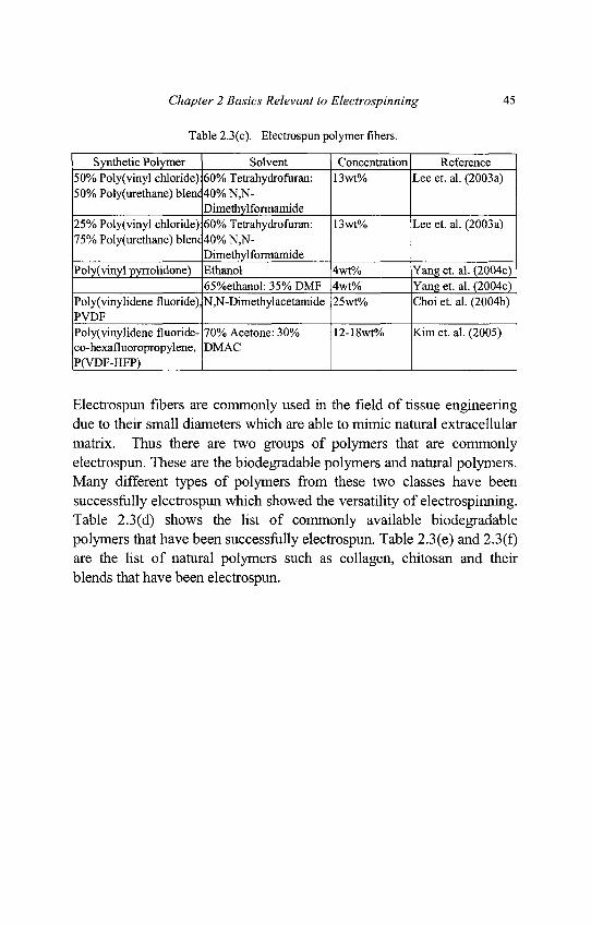
Table 2.3(c). Electrospun polymer fibers.
Synthetic Polymer Solvent Concentration Reference50% Poly(vinyl chloride) 60% Tetrahydrofuran: 13wt% Lee et. al. (2003a)50% Poly(urethane) blent 40% N,N-
Dimethylformamide25% Poly(vinyl chloride) 60% Tetrahydrofuran: 13wt% Lee et. al. (2003a)75% Poly(urethane) blenc 40% N,N-
DimethylformamidePoly(vinyl pyrrolidone) Ethanol 4wt% Yang et. al. (2004c)
65%ethanol: 35% DMF 4wt% Yang et. al. (2004c)Poly(vinylidene fluoride), N,N-Dimethylacetamide 25wt% Choiet. al. (2004b)PVDFPoly(vinylidene fluoride- 70% Acetone: 30% 12-18wt% Kim et. al. (2005)co-hexafluoropropylene, DMACP(VDF-HFP) I | |
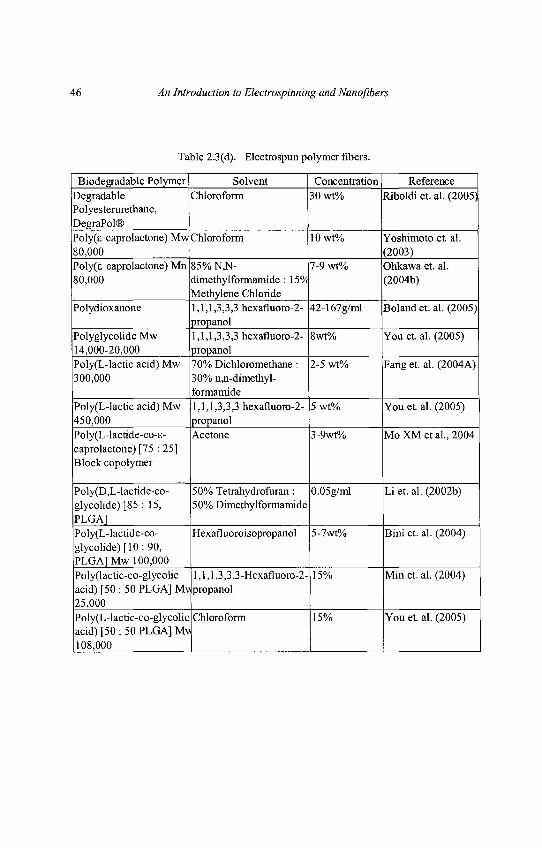
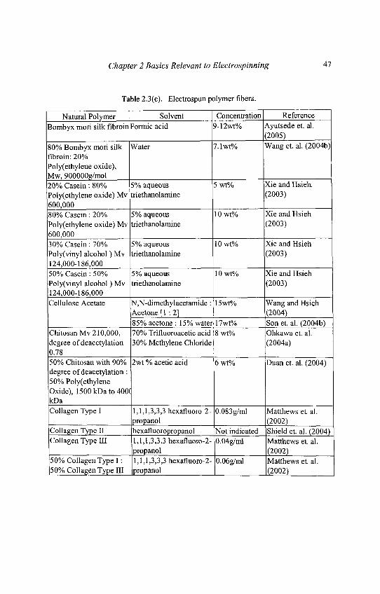
Electrospun fibers are commonly used in the field of tissue engineeringdue to their small diameters which are able to mimic natural extracellularmatrix. Thus there are two groups of polymers that are commonlyelectrospun. These are the biodegradable polymers and natural polymers.Many different types of polymers from these two classes have beensuccessfully electrospun which showed the versatility of electrospinning.Table 2.3(d) shows the list of commonly available biodegradablepolymers that have been successfully electrospun. Table 2.3(e) and 2.3(f)are the list of natural polymers such as collagen, chitosan and theirblends that have been electrospun.
46 An Introduction to Electrospinning and Nanoflbers
Table 2.3(d). Electrospun polymer fibers.
Biodegradable Polymer Solvent Concentration ReferenceDegradable Chloroform 30 wt% Riboldi et. al. (2005)Polyesterure thane,DegraPol®Poly(s-caprolactone) Mw Chloroform 10wt% Yoshimoto et al.80,000 (2003)Poly(s-caprolactone) Mn 85% N,N- 7-9 wt% Ohkawa et. al.80,000 dimethylformamide : 15°/ (2004b)
Methylene ChloridePolydioxanone 1,1,1,3,3,3 hexafluoro-2- 42-167g/ml Boland et. al. (2005)
propanolPolyglycolide Mw 1,1,1,3,3,3 hexafluoro-2- 8wt% You et al. (2005)14,000-20,000 propanolPoly(L-lactic acid) Mw 70% Dichloromethane : 2-5 wt% Fang et. al. (2004A)300,000 30% n,n-dimethyl-
formamidePoly(L-lactic acid) Mw 1,1,1,3,3,3 hexafluoro-2- 5 wt% You et al. (2005)450,000 propanolPoly(L-lactide-co-s- Acetone 3-9wt% MoXM etal., 2004caprolactone) [75 : 25]Block copolymer
Poly(D,L-lactide-co- 50% Tetrahydrofuran : 0.05g/ml Li et. al. (2002b)glycolide) [85 : 15, 50% DimethylformamidePLGA]Poly(L-lactide-co- Hexafluoroisopropanol 5-7wt% Bini et. al. (2004)glycolide) [10: 90,PLGA1 Mw 100,000Poly(lactic-co-glycolic 1,1,1,3,3,3-Hexafluoro-2- 15% Min et. al. (2004)acid) [50 : 50 PLGA] Mv propanol25,000Poly(L-lactic-co-glycolic Chloroform 15% You et al. (2005)acid) [50 : 50 PLGA] Mv108,000 ] I I
Chapter 2 Basics Relevant to Electrospinning 47
Table 2.3(e). Electrospun polymer fibers.
Natural Polymer Solvent Concentration ReferenceBombyxmori silk fibroin Formic acid 9-12wt% Ayutsede et. al.
(2005)80% Bombyx mori silk Water 7.1wt% Wang et. al. (2004b)fibroin: 20%Poly(ethylene oxide),Mw, 900000g/mol20% Casein: 80% 5% aqueous 5 vrt% Xie and Hsieh.Poly(ethylene oxide) Mv triethanolamine (2003)600,00080% Casein: 20% 5% aqueous 10wt% Xie and HsiehPoly(ethylene oxide) Mv triethanolamine (2003)600,00030% Casein: 70% 5% aqueous 10wt% Xie and HsiehPoly(vinyl alcohol) Mv triethanolamine (2003)124,000-186,00050% Casein: 50% 5% aqueous 10wt% Xie and HsiehPoly(vinyl alcohol) Mv triethanolamine (2003)124,000-186,000Cellulose Acetate N,N-dimethylacetamide : 15wt% Wang and Hsieh
Acetone [1 -. 2] (2004)85% acetone : 15% water 17wt% Son et. al. (2004b)
ChitosanMv 210,000, 70% Trifluoroacetic acid 8 wt% Ohkawa et. al.degree of deacetylation 30% Methylene Chloride (2004a)0.7850% Chitosan with 90% 2wt % acetic acid 6 wt% Duan et. al. (2004)degree of deacetylation :50% PolyethyleneOxide), 1500kDato400(kDaCollagen Type I 1,1,1,3,3,3 hexafluoro-2- 0.083g/ml Matthews et. al.
propanol (2002)Collagen Type II hexafluoropropanol Not indicated Shield et. al. (2004)Collagen Type III 1,1,1,3,3,3 hexafluoro-2- 0.04g/ml Matthews et al.
propanol (2002)50% Collagen Type I: 1,1,1,3,3,3 hexafluoro-2- 0.06g/ml Matthews et al.50% Collagen Type HI [propanol | |(2002)
48 An Introduction to Electrospinning and Nanofibers
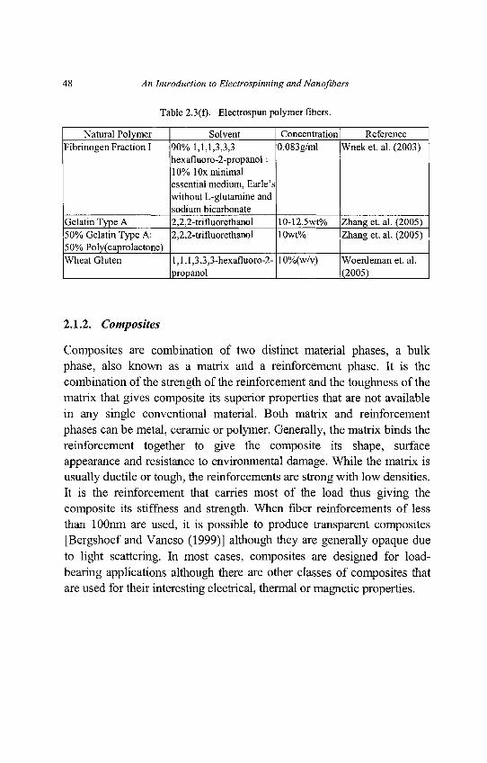
Table 2.3(f). Electrospun polymer fibers.
Natural Polymer Solvent Concentration ReferenceFibrinogen Fraction I 90% 1,1,1,3,3,3 0.083g/ml Wnek et. al. (2003)
hexafluoro-2-propanol:10% 1 Ox minimalessential medium, Earle'swithout L-glutamine andsodium bicarbonate
Gelatin Type A 2,2,2-trifluorethanol 10-12.5wt% Zhang et. al. (2005)50% Gelatin Type A: 2,2,2-trifluorethanol 10wt% Zhang et. al. (2005)50% Poly(caprolactone)Wheat Gluten l,l,l,3,3,3-hexafluoro-2- 10%(w/v) Woerdeman et. al.
propanol (2005)
2.1.2. Composites
Composites are combination of two distinct material phases, a bulkphase, also known as a matrix and a reinforcement phase. It is thecombination of the strength of the reinforcement and the toughness of thematrix that gives composite its superior properties that are not availablein any single conventional material. Both matrix and reinforcementphases can be metal, ceramic or polymer. Generally, the matrix binds thereinforcement together to give the composite its shape, surfaceappearance and resistance to environmental damage. While the matrix isusually ductile or tough, the reinforcements are strong with low densities.It is the reinforcement that carries most of the load thus giving thecomposite its stiffness and strength. When fiber reinforcements of lessthan lOOnm are used, it is possible to produce transparent composites[Bergshoef and Vancso (1999)] although they are generally opaque dueto light scattering. In most cases, composites are designed for load-bearing applications although there are other classes of composites thatare used for their interesting electrical, thermal or magnetic properties.
Chapter 2 Basics Relevant to Electrospinning 49
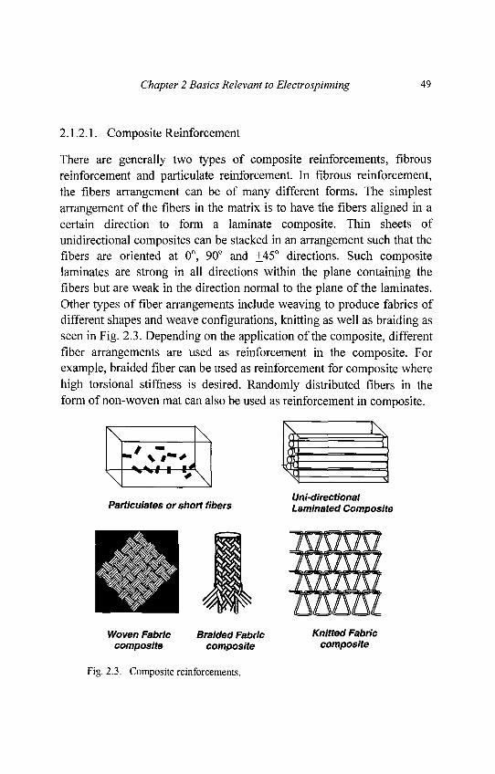
2.1.2.1. Composite Reinforcement
There are generally two types of composite reinforcements, fibrousreinforcement and particulate reinforcement. In fibrous reinforcement,the fibers arrangement can be of many different forms. The simplestarrangement of the fibers in the matrix is to have the fibers aligned in acertain direction to form a laminate composite. Thin sheets ofunidirectional composites can be stacked in an arrangement such that thefibers are oriented at 0°, 90° and +45° directions. Such compositelaminates are strong in all directions within the plane containing thefibers but are weak in the direction normal to the plane of the laminates.Other types of fiber arrangements include weaving to produce fabrics ofdifferent shapes and weave configurations, knitting as well as braiding asseen in Fig. 2.3. Depending on the application of the composite, differentfiber arrangements are used as reinforcement in the composite. Forexample, braided fiber can be used as reinforcement for composite wherehigh torsional stiffness is desired. Randomly distributed fibers in theform of non-woven mat can also be used as reinforcement in composite.
Fig. 2.3. Composite reinforcements.
50 An Introduction to Electrospinning and Nanofibers
In particulate reinforcement, the reinforcing phase has roughly equaldimensions in all directions. The material is known as aggregatecomposite. The reinforcing particles need not be equal sizes as in thecase of concrete and the volume fraction of the particles can be higherthan that of the matrix. The irregularly shaped particles provide strengththrough mechanical interlocking. Another form of aggregate compositeis known as particulate composite. In this case, the volume fraction of theparticles is much lower than that of the matrix. In conventionalcomposites, the thermal expansion mismatch of the particle matrixmaterial will result in high dislocation density in the matrix duringcooling from the fabrication temperature. The resultant strain hardeningcontributes significantly to the strength of the composite. Nanofibercomposites of nylon 6 with Closite 30B [Fong et. al. (2002)] andpolyimide with single wall nanotubes [Park et. al. (2002)] werefabricated by electrospinning.
2.1.2.2. Polymer-Matrix composite
Polymer-matrix composite is the most common form of composite to beused in the industry. Although thermosetting resins is the mostcommonly used polymer matrix, thermoplastic is able to dominate incomposites where short fibers are incorporated. Despite the hugeselection of engineering plastics, only a few are selected as matrix.Important issues when selecting polymer matrix depends mainly onreinforcement-matrix compatibility in terms of bonding, mechanicalproperties, thermal properties, cost etc. Although traditionally used inload-bearing applications, polymer-matrix composite has found uses inother areas.
Conducting polymer such as polyaniline is blend with other polymers toform conducting composites [Chipara et. al. (2003)]. Enzymes embeddedin polymer can be used as biosensors [Sawicka et. al. (2005)]. Metalparticles are also added polymer matrix to produce conductive polymercomposite which can be used to provide shielding for electromagneticinterference and electrostatic discharge [Bigg (1979)].
Chapter 2 Basics Relevant to Electrospinning 51
Another way is to use metals as fillers on top of the polymer matrix and areinforcement material such as carbon fibers [Chen et. al. (2002)].Carbon fiber is preferred in this case as it has good conductivity and atthe same time provides excellent mechanical strength to the composite.This has lead to the development of carbon nanofibers for use asreinforcement in composites [Dzenis and Wen (2002)]. Presence ofcarbon nanotubes in electrospun fibers has shown significantimprovement in the strength of the fibers [Ye et. al. (2004); Ko et. al.(2003)]. Composite consisting of polymer matrix with ceramic particlescan also be used to form two-phase piezoelectric composites [Tressler et.al. (1999)].
2.1.3. Ceramics
Unlike polymer, where there is usually no need for post-electrospinningprocess, ceramics nanofibers can be made from electrospinning of theceramic precursors and followed by sintering of the electrospun fibers toderive ceramic fibers [Dai et. al. (2002); Madhugiri et. al. (2004); Shaoet. al. (2004c)]. Ceramics are materials that composed of both metallicand non-metallic elements and commonly exist as compounds of oxides,nitrides and carbides. While most ceramics are crystalline, there arecommon non-crystalline ceramics like window glass which is made ofsilicon dioxide. As the atomic bonding is either ionic and/or covalent,there are no "free" electrons in ceramics making them, excellentinsulators. The strong ionic and covalent bonding gives the complexstructure of ceramics many advantages such as high temperaturestability, resistance to chemical attacks and adsorption of foreign. Suchrigid configuration also gives ceramics their brittleness.
With advances in technology, ceramics have move away from traditionalapplications which depends largely on its insulating properties andmechanical hardness. Ceramics have found uses as biomaterials[Niklason (2000)] such as calcium carbonate-based ceramics andhydroxyapatite ceramics. Nanoscale ceramics are being manufacturedand found huge potential in many areas due to its high surface area tovolume ratio.
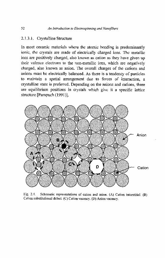
52 An Introduction to Electrospinning and Nanqfibers
2.1.3.1. Crystalline Structure
In most ceramic materials where the atomic bonding is predominantlyionic, the crystals are made of electrically charged ions. The metallicions are positively charged, also known as cation as they have given uptheir valence electrons to the non-metallic ions, which are negativelycharged, also known as anion. The overall charges of the cations andanions must be electrically balanced. As there is a tendency of particlesto maintain a spatial arrangement due to forces of interaction, acrystalline state is preferred. Depending on the anions and cations, thereare equilibrium positions in crystals which give it a specific latticestructure [Pampuch (1991)].
/"— \-r—'Vr—~\J^—v-r"—~\/~ v/ — Vr'—\
I W I I J f \ D I X ^ 7 Cation
Fig. 2.4. Schematic representations of cation and anion. (A) Cation interstitial. (B)Cation substitutional defect. (C) Cation vacancy. (D) Anion vacancy.
Chapter 2 Basics Relevant to Electrospinning 53
In real crystals, there are a number of defects in their structure. Atomicpoint defects in the form of vacancies and interstitials are possible inceramic crystals as shown in Fig. 2.4. However, as there are both anionsand cations in a ceramic crystal, defects for each ion type may occur.While defects in the form of anion or cation vacancy and cationinterstitial are possible, it is highly improbable for anion interstitial tooccur due to the large anion size. Impurities may also be found in theceramic crystal. The impurity may cause either interstitial defects orsubstitutional defects. For an interstitial defect, the impurity must berelatively small compared to the anion. As for substitutional defect, theimpurity will displace the host ion which it is most similar in electricalsense. For example, if the impurity usually forms a cation, it willdisplace the host cation.
2.1.3.2. Amorphous Structure
At the other extreme of crystalline structure is the highly disorderedstructure, which gives rise to amorphous materials. Typical amorphousceramics include one component glasses, multi-component alkali-silicaglasses, chalcogenide-based glasses, amorphous semi-conductingmaterials like silicon and amorphous metals. Amorphous glasses aregenerally made from solidification of liquids under conditions whichdoes not favor the formation of crystals. For window glasses, coolingrate of a few lO^Ks"1 will avoid crystallization while metallic glassesrequire 10s to 106Ks-\
Recently, metal-organic polymers are used as precursors to formceramics after calcinations at high temperature [Viswanathamurthi et. al.(2004c)]. The resulting ceramic after the decomposition process isusually amorphous. However, this phase is only stable up to atemperature, Tc, when a microcrystalline structure will start to appear[Soraru et. al. (1988)].
54 An Introduction to Electrospinning and Nanofibers
2.1.3.3. C eramic B iomaterials
Ceramics including glasses have been widely used in many biomedicalapplications such as diagnostic instruments, porous glasses as carriers forantibodies and restorative dental materials. Due to its excellent wearresistance, good biocompatibility and corrosion resistance, ceramics arealso frequently used in load bearing prosthesis. Alumina has been used inorthopedic surgery for more than two decades. Recently, Zirconia oxideis used as the articulating ball in total hip prostheses.
The use of porous ceramic implant is used to encourage bone growthwithin the interconnecting pore channels with pore size exceeding100|im. Such ceramics are used in nonload-bearing applications. Porousceramics are commonly manufactured from the microstructures ofcertain corals [Niklason (2000)]. Other methods have also been exploredto create porous ceramic implants. For example bacterial thread has beeninfiltrated with silica nanoparticles to form ordered porous ceramicarchitecture [Davis et. al. (1997)].
Bioresorbable ceramics have also been widely tested as artificial bonesubstitute. Hydroxyapatite ceramics is one of the most commonly usedbioresorbable ceramics as it can be found naturally in bones. In fact,natural hydroxyapatite ceramics has been studied in great details for useas implants [Joschek et. al. (2000)]. Although man-made hydroxyapatiteceramics are slightly different from its natural counterpart [McCormell(1965)], investigations have shown promising results as bone substitute.Man-made silicon-stabilized calcium phosphate ceramics withinterconnected morphology can be resorbed when osteoclasts arecultured on it. Bonding of the implant to new bone was found to beexcellent with evidence of remodeling of implant interface by theosteoclasts [Langstaff et. al. (2001)].
Chapter 2 Basics Relevant to Electrospinning 55
2.1.3.4. Nanostructured Ceramics
Traditionally, ceramics are often used as reinforcement materials incomposites. Ceramic nanoparticles have already been widely used asparticle reinforcements. Other ceramic nanostructures such as fibers[Choi and Lee (2003); Dai et. al. (2002)] and tubes [Wang et. al. (2004a);Li et. al. (2004a)] have also been developed which can be used as fiberreinforcement or ceramic filters. Nanoscale Alumina-borate oxide fibershave successfully been electrospun to form a random mesh [Dai et. al.(2002)] which may have the potential for use as ceramic filters.
Nanostructured ceramics are also desirable in other applications such asmicroelectronic devices, chemical and biological sensing and diagnosis,energy conversion, catalysis and drug delivery. The huge range ofceramics with their unique properties has found new applications as wellas enhanced performance when reduced to nanoscale. For example, thesensitivity of ZnO gas sensor is affected by the specific surface area ofZnO [Xu et. al. (2000)]. Silica being hydrophilic, easy formation ofcolloidal suspension and surface functionalizing has been fabricated intonanotubes [Wang et. al. (2004a)] and nanofibers [Choi and Lee (2003)].
Various ceramic materials have been expected to have applications ascatalyst, sensors, solar cells and electro-optical devices, to name a few.As such, the researcher's emphasis has been placed on the fabrication ofceramics nanofibers which have high total surface area as compared tobulk ceramics, as shown in Table 2.4. To date, most reports describe thefabrication method of ceramics nanofibers and investigated the averagefiber diameter through Scanning Electron Microscope (SEM), fibersurface morphology through Atomic Force Microscope (AFM) and theexistence of ceramics phase in the nanofibers through X-ray Diffraction(XRD) and Fourier Transform Infrared Spectroscopy (FT-IR).
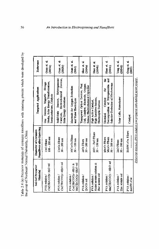
Tab
le 2
.4 (
a) P
recu
rsor
mat
eria
ls o
f ce
ram
ics
nano
fiber
s w
ith s
inte
ring
proc
ess
whi
ch w
ere
deve
lope
d by
the
grou
p of
Nor
thea
st N
orm
al U
nive
rsity
, Chi
na.
Sol-G
el P
recu
rsor
Mat
eria
l
PVA
sol
utio
n /
Cu(
CH
3CO
O)2
-IC
Oso
l
PV
A s
olut
ion
/C
o(C
HsC
OO
)2- 4
H5O
sol
PV
A s
olut
ion
/C
o(C
H3C
OO
)2- 4
HzO
&N
i(C
H3C
OO
>-
4HaO
sol
PV
A s
olut
ion
/Z
rOC
b so
l
PVA
sol
utio
n /
Nic
kel
acet
ate
solu
tion
&Z
inc
acet
ate
sol
PVA
sol
utio
n /
Mn(
CH
3CO
O)2
-4H
JO s
ol
PVA
sol
utio
n /
Zin
c ac
etat
e so
l
PVA
sol
utio
n /
H4S
iWl2
O40
Dia
met
er o
f C
eram
ics
Nsn
oObt
rs a
fter
Sin
teri
ng
CuO
Fib
ers
10
0- 2
00
nm
CO
3O4
Fib
ers
50 ~
200
nm
NiC
osO
t Fi
bers
50 ~
150
nm
Z1O
1 F
iber
s50
~ 2
00 n
m
Ni O
- Zn
O F
iber
s50
~ 1
50 n
m
Mn2
O3
Fib
ers
MI1
3O4
Fib
ers
50 ~
200
am
ZiiO
Fib
ers
50 ~
100
nm
H4S
iWuO
« F
iber
s
Tar
gete
d A
ppli
cati
ons
Gas
S
enso
rs,
Mag
netic
S
tora
geM
edia
, So
lar
Ene
rgy
Tra
nsfo
rmat
ion,
Sem
icon
duct
ors,
Cat
alys
is
Solid
-Sta
te
Sen
sors
, H
eter
ogen
eous
Cat
alys
ts,
Ele
ctro
chem
ical
D
evic
es,
Sola
r E
nerg
y A
bsor
bers
Ele
ctro
de f
or O
xyge
n R
educ
tion
and
Wat
er E
lect
roly
sis
Tra
nspa
rent
Opt
ical
Dev
ices
, Fu
elC
ell,
Cat
alys
t, E
lect
rode
, O
xyge
nSe
nsor
, Ele
ctro
chem
ical
Cap
acit
or
Hig
h A
ctiv
e C
atal
yst,
Hig
h Se
nsit
ive
Sen
sors
,E
lect
roop
lic
Dev
ices
Ele
ctri
cal
Cat
alys
t fo
r th
eD
ecom
posi
tion
of
N
itro
geno
xide
an
dSe
lect
ive
Red
ucti
on o
f N
itrob
enze
ne
Sola
r C
ells
, Nan
oclu
ster
Cat
alys
t
Ref
eren
ce
Gua
n et
. aL
(200
3a)
Gua
n et
aL
(200
3b)
Gua
n et
. al
.(2
004)
Shao
et.
aL(2
004a
)
Shao
et.
aL(2
004b
)
Shao
et.
aLC
20M
C)
Yan
g et
, aL
(200
4d)
Gon
get.
aL
(200
3)
Pol
y (V
inyl
alc
ohol
) (P
VA
) sol
utio
n w
as p
repa
red
wit
h di
stil
led
wat
er s
olve
nt.
56 An Introduction to Electrospinning and Nanofibers
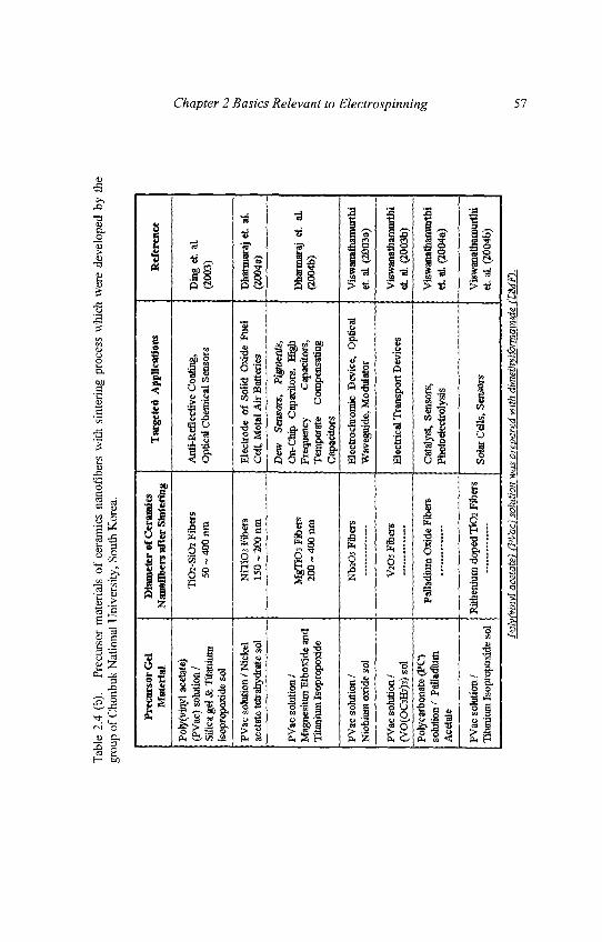
Tab
le 2
.4 (
b).
Prec
urso
r m
ater
ials
of
cera
mic
s na
nofib
ers
with
sin
teri
ng p
roce
ss w
hich
wer
e de
velo
ped
by t
hegr
oup
of C
honb
uk N
atio
nal U
nive
rsity
, So
uth
Kor
ea.
Pre
curs
or G
elM
ater
ial
Poty
(vin
yl a
ceta
te)
(PV
ac)
solu
tion
/Si
lica
gel &
Tita
nium
isop
ropo
xide
sol
PVac
sol
utio
n / N
icke
lac
etat
e te
fr ah
ydra
te s
ol
PVac
sol
utio
n /
Mag
nesi
um E
thox
ide
and
Tita
nium
Isop
ropo
xide
PVac
sol
utio
n /
Nio
bium
oxi
de s
ol
PVac
sol
utio
n /
(VO
(OC
3H7»
sol
Poly
carb
onat
e (P
C)
solu
tion
i' Pa
lladi
umA
ceta
te
PVac
sol
utio
n /
Tita
nium
Isop
ropo
xide
sol
Dia
met
er o
f C
eram
ics
Nan
ofib
ers
afte
r S
inte
ring
TiO
2-Si
O2
Fibe
rs50
~ 4
00 n
ra
NiT
iO3
Fibe
rs15
0 ~
200
tun
Mgl
iOi
Ffce
rs20
0 ~
400
nm
Nta
Os
Fibe
rs
V2O
5 Fi
bers
Palla
dium
Oxi
de F
iber
s
Rith
enhi
m d
oped
T1O
2 Fi
bers
Tar
gete
d A
pplic
atio
ns
Ant
i-Ref
lect
ive
Coa
ting,
Opt
ical
Che
mic
al S
enso
rs
Ele
ctro
de o
f So
lid O
xide
Fue
lC
ell,
Met
al A
ir B
atte
ries
Dew
Se
nsor
s,
Pigm
ents
,O
n-C
Up
Cap
acito
rs,
Hig
hFr
eque
ncy
Cap
acito
rs,
Tem
pera
te
Com
pens
atin
gC
apac
itors
FJec
troch
rom
ic D
evic
e, O
ptic
alW
aveg
uide
, Mod
ulat
or
Ele
ctric
al T
rans
port
Dev
ices
Cat
alys
t, Se
nsor
s,Ph
otoe
lect
roly
sis
Sola
r C
ells
, Sen
sors
Ref
eren
ce
Din
g et
. al
.(2
003)
Dna
rmar
aj e
t al
(200
4 a)
Dha
rmar
aj e
t. al
.(2
004b
)
Vis
wan
atha
mur
thi
et. a
l (2
003a
)
Vis
wan
atha
mur
thi
et a
l. (2
003b
)
Vis
wan
atiia
raui
thi
et. a
l. (2
004a
)
Vis
wan
atha
mur
thi
et. a
L (2
004b
)
Pok
/Cvi
nyl a
ceta
te)
{PV
ac}
solu
tion
was
pre
pare
d w
ith
dim
ethy
lfor
mam
ide
(LS4
FI.
Chapter 2 Basics Relevant to Electrospinning 57
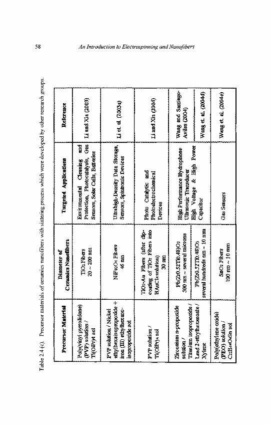
Tab
le 2
.4 (c
). Pr
ecur
sor
mat
eria
ls o
f ce
ram
ics
nano
fiber
s w
ith s
inte
ring
proc
ess
whi
ch w
ere
deve
lope
d by
oth
er re
sear
ch g
roup
s.
Pre
curs
or M
ater
ial
Poly
(vin
yl p
yrro
lidon
e)(P
VP)
sol
utio
n /
Ti(O
iPr>
l so
l
PVP
solu
tion
/ Nic
kel
ethy
lhex
aiso
prop
oxid
e +
iron
(M)
ethy
lhex
ano-
isop
ropo
xide
sol
PVP
solu
tion
/T
i(OiP
r)4
sol
Zirc
oniu
m n
-pro
poxi
deso
lutio
n /
Tita
nium
isop
ropo
srid
e/L
ead
2-et
hylh
exan
oate
/X
ylen
e
Poly
(eth
ylen
e ox
ide)
(PE
O)
solu
tion
/C
22H
44O
4SII
Sol
Dia
met
er o
fC
eram
ics
Nan
ofib
ers
T1O
2 Fi
bers
20 ~
200
nm
NiF
e2O
4 Fi
bers
46 n
m
TiO
2-A
u Fi
bers
(af
ter
dSp-
coat
ing
of T
I OJ
Fibe
rs i
nto
HA
uCk
solu
tion)
30 n
m
Pb(
Zr0
.52m
48)O
350
0 nm
~ s
ever
al m
icro
ns
Pb(2
t0,5
2"T
i0,4
8)O
3se
vera
l hun
dred
s nm
~ 1
0 m
m
SnO
2 F
iba^
100n
m~
10m
tn
Tar
gete
d A
pplic
atio
ns
Env
ironm
enta
l C
lean
ing
and
Prot
ectio
n, P
hoto
cata
lysi
s,
Oas
Sens
ors,
Sol
ar C
ells
, Bat
teri
es
Ultr
ahig
h-D
ensi
ry D
ata
Stor
age,
Sens
ors,
Spi
ntro
nic
Dev
ices
Phot
o C
atar
ytic
an
dPh
otoe
lect
ro ch
emic
alD
evic
es
Hig
ji Pe
rfor
man
ce H
ydro
phon
eU
ltras
onic
Tra
nsdu
cer
Hig
h V
olta
ge
&
Hig
h Po
wer
Cap
acito
r
Gas
Sen
sors
Ref
eren
ce
I i a
nd X
ia (2
003)
Li e
t al
(20
03a)
Li a
nd X
ia (
2004
)
Wan
g an
d Sa
ntia
go-
Avi
les
(200
4)
Wan
g et
. aL
(200
4d)
Wan
g et
al.
(200
4e)
58 An Introduction to Electrospinning and Nanofibers
Chapter 2 Basics Relevant to Electrospinning 59
Other than fabrication study of ceramics nanofibers, no detaileddiscussion about the property of targeted applications has been doneexcept the work of [Li et al., 2003a] which investigated the magneticproperty of nickel ferrite nanofibers. Therefore, property investigation ofpotential applications should be the next challenge of fabricated ceramicsnanofibers. Preparation of ceramics nanofibers includes the preparationof sol-gel precursor of ceramics and sintering process of the electrospunnanofibers.
For example, Shao et al. (2004c) prepared aqueous manganese acetate(Mn(CH3COO)2 • 4H2O) solution (manganese acetate : distilled water =33:66 wt%) and aqueous poly(vinyl alcohol) (PVA) solution with 10wt%polymer concentration. 20 g PVA solution was slowly lowered intomanganese acetate solution and chemical reaction proceeded in a waterbath for a period of 5 hours at a temperature of 50°C.
The obtained PVA/manganese acetate gel was electrospun onto thealuminum foil with an applied voltage of 20kV. The resultant nanofiberwebs were dried at a temperature of 70°C for a period of 12 hours undervacuum condition and then sintering process was performed at 300°C,700°C and 1000°C for 10 hours. During the sintering process, the organicbelonged to PVA and CH3COO group of manganese acetate and othervolatiles (such as H2O, COX, etc) were removed. From the XRD and FT-IR results, sintering process at 700°C resulted in the production of Mn2O3
nanofibers whilst sintering at 1000°C resulted in the production of Mn3O4
ceramics nanofibers. It was shown that sintering condition significantlyinfluences the reaction of ceramics gel and the structure of ceramicsnanofibers.
60 An Introduction to Electrospinning and Nanofibers
2.1.3.5. Carbon
Carbon is the basic building blocks of naturally occurring organiccompounds. As such, pure carbon can be manufactured from a variety ofcarbonaceous precursors. In its pure carbon can exist in three allotropicforms, carbon, graphite and diamond. While carbon as an allotropic formhas an "amorphous" or non-ordered atomic structure, graphite consists ofparallel stacking of carbon atoms in fused hexagonal rings. Because ofthe weak attractive forces between the parallel layers of hexagonal rings,graphite is softer than carbon. In the form of diamond, its tetrahedrallybonded carbon atoms makes it the hardest naturally occurring materialknown to man. Recently, there has been great interest in carbonnanotubes due to its huge potential for many different applications.Carbon nanotube has also been successfully embedded in polymernanofibers by means of electrospinning [Dror et. al. (2003)] or grownfrom the surface of electrospun fibers [Hou et. al. (2004)].
Carbon in its graphite form is a well known stable electrode material as itis free of functional groups which interact with ions in the electrolyte.The large surface area and low resistivity of carbon nanotubes make it aninteresting candidate in electrochemistry. When an electrode is immersedin an electrolyte, there is a potential induced adsorption of solutes ontothe surface of the electrode called electroadsorption. In its simplest case,opposing-charged ions are adsorbed onto the electrode while like-charged ions are repelled. Two layers of charges with a potential drop areformed as a result of the separation of charge with the attracted ionsforming a layer that balanced the charge on the electrode. Thus, anelectrochemical double layer is said to be formed.
Chapter 2 Basics Relevant to Electrospinning 61
Generally, the specific electroadsorption capacity of ions is very small.However, by increasing the electrode surface, such as porous carbonelectrodes, the capacities can be significantly increased [Soffer andFolman (1972)]. While it was also been demonstrated that porous carbonelectrodes can be used for purification of solutions containing suspendedbacteria [Oren et. al. (1983)], carbon nanotube may be used to performthe same function.
Electrochemical double layer can act as a capacitor [Kotz and Carlen.(2000)] if the potential difference across it is less than that needed todissociate the electrolyte. Since capacitance is given by,
C = ^- (2.2)a
where s is the dielectric constant
A is the electrode surface
d is the electrochemical double layer distance
The capacitance can be huge for carbon electrode that has a high areaand low electrochemical double layer distance. Thus this has led to theinvestigation of using carbon nanotube [Emmenegger et. al. (2003)] andelectrospun activated carbon nanofibers [Kim (2004a)] as supercapacitor.
While carbon in the form of graphite is known to be a good conductor ofelectricity, recent interest has been on using carbon nanotubes inelectronics applications [McEuen (1998)]. This is especially so with theminiaturization of electronic devices. Single walled carbon nanotubeshave been experimentally determined to exhibit either metallic behavioror semiconductor behavior depending on the hexagonal-ring structure ofthe wall [Odom et. al. (1998) Dresselhaus (1998)]. Carbon nanotubeshave also been made into field-effect transistors by using a semi-conducting silicon substrate covered with a layer of silicon dioxide as aback-gate and making contacts using lead electrodes [Tan et. al. (1998)].
62 An Introduction to Electrospinning and Nanofibers
However, this design implies that all the devices are switched onsimultaneously. Subsequent improvement involves having a separate'top' gate over the individual nanotube so that the device can be switchedindividually. The transconductance of the carbon nanotube field-effecttransistor was found to be 20 times better than that of conventionalsilicon metal-oxide-semiconductor field-effect transistors [Wind et. al.(2002)].
Carbon nanofibers possess numerous possible applications such asfilters, high temperature catalysts, heat management materials in aircraft,and semiconductor device. [Dzenis and Wen (2002)] made carbonnanofibers with 100 ~ 500 nm fiber diameter and the utilization ofcarbon nanofibers. Carbon nanofibers have been expected asreinforcement of traditional fiber reinforced polymer composites. Thehigh electrical conductivity of carbon nanofibers also opens up thepotential for application such as sensor devices [Wang et. al. (2002a)].The fabricated carbon nanofibers demonstrated a high electricalconductivity (490 S/m). Fabrication process of carbon nanofiberscontains electrospinning of polyacrylonitrile (PAN) nanofibers andcarbonization of deposited nanofibers. A research group at theUniversity of Pennsylvania [Wang et. al. (2002a); Wang et. al. (2003);Santiago-Aviles and Wang (2003)] prepared Dimethylformamide (DMF)solution mixed with PAN powder (PAN : DMF = 600 mg : 10ml). Thismixture was well stirred at room temperature. After PAN nanofiberdeposition through electrospinning process (15kV applied voltage, 15cmdistance), the fibers were carbonized at 560°C, 800°C, 1000°C and1200°C respectively for 30 minutes with 10"6 Torr pressure undervacuuming [Wang et. al. (2003)]. Raman spectra characterizationshowed that the graphite domain size in carbon nanofibers was enlargedfrom 1.5 to 2.6nm with higher carbonization temperature. Theconductivity of carbon nanofibers was also influenced by thecarbonization time. It was concluded that the transformation ofdisordered carbon into graphitic carbon is a highly kinetically controlledprocess. Hence carbonization condition (i.e. temperature and time) isvery important to control the structure and property of carbon nanofibers.
Chapter 2 Basics Relevant to Electrospinning 63
2.2. Solution Property
In order to carry out electrospinning, the polymer must first be in a liquidform, either as molten polymer or as polymer solution. The property ofthe solution plays a significant part in the electrospinning process and theresultant fiber morphology. During the electrospinning process, thepolymer solution will be drawn from the tip of the needle. The electricalproperty of the solution, surface tension and viscosity will determine theamount of stretching of the solution. The rate of evaporation will alsohave an influence on the viscosity of the solution as it is being stretched.The solubility of the polymer in the solvent not only determines theviscosity of the solution but also the types of polymer that can be mixedtogether.
2.2.1. Surface Tension
In electrospinning, the charges on the polymer solution must be highenough to overcome the surface tension of the solution. As the solutionjet accelerates from the tip of the source to the collector, the solution isstretched while surface tension of the solution may cause the solution tobreakup into droplets [Shummer and Tebel (1983); Christanti andWalker (2001)]. When droplets are collected, a different process calledelectrospraying [Morozov et. al. (1998)] is taking place rather thanelectrospinning, where fibers are collected instead. Surface tension hasalso been attributed to the formation of beads on the electrospun fibers.Thus it is important to understand the role of surface tension in a fluid.
When a very small drop of water falls through the air, the dropletgenerally takes up a spherical shape. The liquid surface property thatcauses this phenomenon is known as surface tension. For a liquidmolecule submerged within the solution, there is uniform attractiveforces exerted on it be other liquid molecules surrounding it. However,for a liquid molecule at the surface of the solution, there is a netdownward force as the liquid molecules below exert a greater attractiveforce than the gas molecules above as shown in Fig. 2.5.
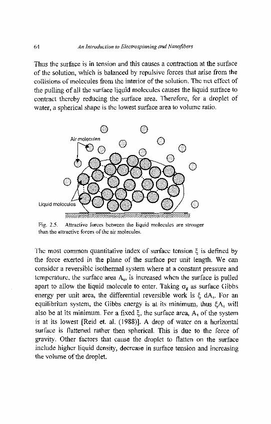
64 An Introduction to Electrospinning and Nanqfibers
Thus the surface is in tension and this causes a contraction at the surfaceof the solution, which is balanced by repulsive forces that arise from thecollisions of molecules from the interior of the solution. The net effect ofthe pulling of all the surface liquid molecules causes the liquid surface tocontract thereby reducing the surface area. Therefore, for a droplet ofwater, a spherical shape is the lowest surface area to volume ratio.
Fig. 2.5. Attractive forces between the liquid molecules are strongerthan the attractive forces of the air molecules.
The most common quantitative index of surface tension £, is defined bythe force exerted in the plane of the surface per unit length. We canconsider a reversible isothermal system where at a constant pressure andtemperature, the surface area As, is increased when the surface is pulledapart to allow the liquid molecule to enter. Taking ag as surface Gibbsenergy per unit area, the differential reversible work is £ dAs. For anequilibrium system, the Gibbs energy is at its minimum, thus £,AS willalso be at its minimum. For a fixed £, the surface area, As of the systemis at its lowest [Reid et. al. (1988)]. A drop of water on a horizontalsurface is flattened rather then spherical. This is due to the force ofgravity. Other factors that cause the droplet to flatten on the surfaceinclude higher liquid density, decrease in surface tension and increasingthe volume of the droplet.
Chapter 2 Basics Relevant to Electrospinning 65
2.2.1.1. Effect of Temperature on Surface Tension
For a pure liquid system, the surface tension of the liquid would decreasewith increasing temperature. When the temperature is raised, theequilibrium between the surface tension and the vapor pressure woulddecrease. At a critical point, the interface between the liquid and the gasdisappears [Clark (1938)]. From the molecular point of view, at a highertemperature, the liquid molecules gain more energy and start to movemore rapidly in the space. As a result, the fast moving molecules do notbound together as strongly as the molecules in a cooler liquid. With thereduction in the bonding between the molecules, the surface tensiondrops. The effect of temperature on surface tension for pure liquid maybe different from mixtures. For a mixture of methane and nonane, thesurface tension actually increases with increasing temperature except atthe lowest pressure. At a lower temperature, methane is more solublethan nonane and the effect of liquid mixture composition is morepronounce than temperature in the determination of the surface tension[Deam and Maddox (1970)]
2.2.1.2. Surface Tension of Solvent Mixtures
For a mixture, the surface tension is not a simple function of the surfacetension of the pure components, hi a mixture, the composition at thesurface is often different from that of the bulk. The surface tension of themixture of non-aqueous solution can be approximated by a lineardependence on the mole fraction average of the surface tension of thepure components. For aqueous solution, the surface tension showspronounced nonlinear characteristics. In an organic-aqueous system, asmall amount of organic liquid may significantly affect the mixturesurface tension. This is due to hydrophobic behavior of a small amountof organic molecules, which tend to be rejected from the water phase andconcentrating on the surface. As a result, the surface composition of themixture is very different from that of bulk.
66 An Introduction to Electrospinning and Nanofibers
2.2.2. Polymer Solubility
Although molten polymers can be electrospun [Lyons and Ko. (2004);Larrondo and Manley (1981a); Larrondo and Manley (1981b); Larrondoand Manley (1981c)], it is more common to electrospin using polymersolution. Since different solvents have different level ofelectrospinnability [Jarusuwannapoom et. al. (2005)] it is important touse an appropriate solvent that can dissolve the polymer and at the sametime electrospinnable. The solubility of the polymer in a particularsolvent may also affect the resultant fiber morphology [Wannatong et. al.(2004)].
Polymer solubility is more complex than those of low-molecular weightcompound due to size difference between polymer and solventmolecules, viscosity of the system, effects of the structure and molecularweight of the polymer. There are two stages when a polymer dissolves inthe solvent. Firstly, solvent molecules diffuse slowly into the polymerbulk to produce a swollen gel. If the polymer-polymer intermolecularforces are high as a result of cross-linking, crystallinity or stronghydrogen bonding, the polymer-solvent interactions may not be strongenough to break the polymer-polymer bond. The second stage of solutionwill only take place when the polymer-polymer bond is broken to givetrue solution.
2.2.2.1. Effect of Polymer Structure on Solubility
The structure of the polymer has an impact on its solubility in thesolvent. Generally, a polymer with higher molecular weight is lesssoluble and takes a much longer time to dissolve than one with a lowermolecular weight using the same solvent. The intermolecular forcesbetween longer chain molecules are stronger and the solvent moleculestake a longer time to diffuse into the polymer bulk. Crosslinked polymersdo not dissolve, as covalent bonding between the molecules is muchstronger than the secondary forces exerted from polymer-solventinteractions.
Chapter 2 Basics Relevant to Electrospinning 67
Crystallinity of the polymer measures the degree of orderliness of thepolymer chain packed within the bulk. Polymer of higher crystallinityhas lower solubility as the solvent molecules have difficulty inpenetrating the interior of the polymer bulk.
2.2.2.2. Gibbs Free Energy
In discussing the solubility of the polymer in a system, it is useful tomake use of Gibbs free energy.
AG = AH-TAS (2.3)
where, AG is the Gibbs free energy,AH is the heat of mixing or enthalpyT is TemperatureAS is Entropy of mixing
A good solvent causes the polymer to expand to reduce the overall Gibbsfree energy of the system. In a poor solvent, the polymer molecules willcurl up or collapse to reduce the overall Gibbs free energy. Solubilityoccurs when the Gibbs free energy give a negative value. As seen fromequation (2.3), the temperature has an influence on whether the solvent isa "good" or "poor" solvent. The lowest temperature at which a polymerof infinite molecular weight is completely soluble in a specific solvent isknown as Flory-Huggins temperature, 0. At a higher temperature, thepolymer will expand while at a lower temperature, the polymer willcollapse.
The entropy of mixing AS is long thought to be positive thus the sign ofAG is also determined by the sign and magnitude of the heat of mixingAH. For non-polar molecules, AH is assumed to be positive and the sameas those derived from the mixing of small molecules. The enthalpy frommixing a solute and a solvent is proportional to the square of thedifference in solubility parameters [Hildebrand and Robert (1950)].
68 An Introduction to Electrospinning and Nanofibers
Atf^v^-jJ2 (2.4)
where AH is the heat of mixing or enthalpyvs and vp is the partial volume of solvent and polymerrespectivelySs and Sp is the solubility parameter of solvent and polymerrespectively
Seen from equation of Gibbs free energy (2.3), AG will have a negativevalue if AH approaches zero and thus, solution will occur. For non-polarsolvents, the solubility parameter Ss, is a function of enthalpy ofevaporation, temperature and molar volume.
Ss=j{AHv-RT)/VM (2.5)
where AHV is the Enthalpy of evaporationR is the ideal gas constantT is temperature in KelvinVM is the molar volume
To determine the solubility, Sp, for a non-polar polymer of knownstructure, molar-attraction constants EM, are summed over the structuralconfiguration of the repeating unit in the polymer chain,
where 8P is the solubility of polymerp is the densityEM is the molar-attraction constantsM is the repeat molecular weight.
Chapter 2 Basics Relevant to Electrospinning 69
2.2.3 Viscosity
The viscosity of the solution has a profound effect on electrospinningand the resultant fiber morphology. Generally, the viscosity of thesolution is related to the extent of polymer molecule chains entanglementwithin the solution. When the viscosity of the solution is too low,electrospraying may occur and polymer particles are formed instead offibers. At lower viscosity where generally the polymer chainentanglements are lower, there is a higher likelihood that beaded fibersare obtained instead of smooth fibers. Therefore, factors that affect theviscosity of the solution will also affect the electrospinning process andthe resultant fibers.
A liquid under normal experimental considerations will respond to shearstress by flowing. The shearing stress/is the force required to move aplane relative to another which is dependent on a proportionality factor,called coefficient of shear viscosity or viscosity is introduced. Therefore,
where rj is viscosityds/dt is the rate of shear
Viscosity is a measure of the resistance of a material to flow. There areseveral forms of viscosities, relative viscosity (77,.) is the ratio of theviscosity of a polymer solution to that of its solvent. Relative viscosityminus the viscosity of water (1) is the specific viscosity (rjsp). Reducedviscosity or viscosity number (rjred) is by dividing TJSP by theconcentration of the solution, c. Finally, the intrinsic viscosity or limitingviscosity number ([ rj\) is obtained by extrapolating reduced rjred to zeroconcentration.
70 An Introduction to Electrospinning and Nanofibers
The intrinsic viscosity is related to the average molecular weight of thepolymer (M) of the polymer by a proportionality constant, K, which isthe characteristic of the polymer and solvent and the exponential a,which is a function of the shape of polymer coil in a solution.
[rj) = KMa (2.8)
[rj] is also found to be directly proportional to the effectivehydrodynamic volume of the polymer in solution and inverselyproportional to the molecular weight {M). The effective hydrodynamicvolume is the cube of the root-mean-square of the end-to-end distance of
the molecule, J ~ .
r, 4?)"M
where K is the proportionality constant in the Flory equation forhydrodynamic volume.
Table 2.5 shows a summary of the various viscometry terms and theircorresponding formula.
In a polymer solution, the configuration that is adopted by the polymerchain will affect the intrinsic viscosity of the solution. An extended oruncurled configuration of the polymer chain molecules is associated withan increase in the intrinsic viscosity of the solution. While polymerchains that adopt a curled configuration in the solvent will result in adrop in the intrinsic viscosity.
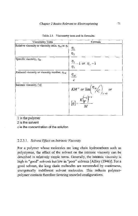
Chapter 2 Basics Relevant to Electrospinning 71
Table 2.5. Viscometry term and its formulas.
Viscometry Term FormulaRelative viscosity or viscosity ratio, r\rei or t]r
HL
Specific viscosity, rjsp
^ 1 — 1 or / 7 r - l
Reduced viscosity or viscosity number, r]re(i
C
Intrinsic viscosity, [rj] / /\
KM" orlim\7?'p/,\ or
1 J M
1 is the polymer2 is the solventc is the concentration of the solution
2.2.3.1. Solvent Effect on Intrinsic Viscosity
For a polymer whose molecules are long chain hydrocarbons such aspolystyrene, the effect of the solvent on the intrinsic viscosity can bedescribed in relatively simple terms. Generally, the intrinsic viscosity ishigh in "good" solvents but low in "poor" solvents [Alfrey (1946)]. For agood solvent, the long chain molecules are surrounded by continuous,energetically indifferent solvent molecules. This reduces polymer-polymer contacts therefore favoring uncurled configurations.
72 An Introduction to Electrospinning and Nanoflbers
However, in a poor solvent, which is energetically unfavorable, thedissolving of the polymer is an endothermic process and the polymersegments will be attracted to one another in the solution and squeeze outthe solvent between them. The polymer chains will adopt a curledconfiguration. Depending on the solubility of the polymer in the solvent,a good solvent allows a higher concentration of the polymer whilemaintaining a fluid, stable solution whereas a poorer solvent will havemore polymer-polymer contacts between different chains and lead togelation. The effect of solvent on the intrinsic viscosity also depends onthe flexibility of the polymer chain. If the polymer chain is more rigid,the solvent effect on the intrinsic viscosity is less [Alfrey et. al. (1942)].
2.2.3.2. Temperature on Intrinsic Viscosity
Generally, when the temperature of the solution is increased, thesolubility of the polymer in the solvent will increase. In pure solvents,specific viscosity decreases with increase in temperature. This is due tohigher polymer chain mobility. The dependency of intrinsic viscosity ontemperature can be shown by,
[rj]=BeE-IRT (2.10)
where Ea is an activation energy for viscous flowB is a constantR is the ideal gas constantT is the temperature in Kelvin
However, if the initial temperature is below the Flory-Hugginstemperature 6, the viscosity will increase when the mixture of polymerand solvent is heated to slightly above 6. In a mixed system where themixture of good and poor solvents is used to dissolve the polymer,specific viscosity may increase with temperature. This is the result ofuncurling of the molecule due to the increase of entropy factors overenergetic factors when the temperature is increased [Alfrey et. al. (1942)]to 0 of the solvent mixtures.
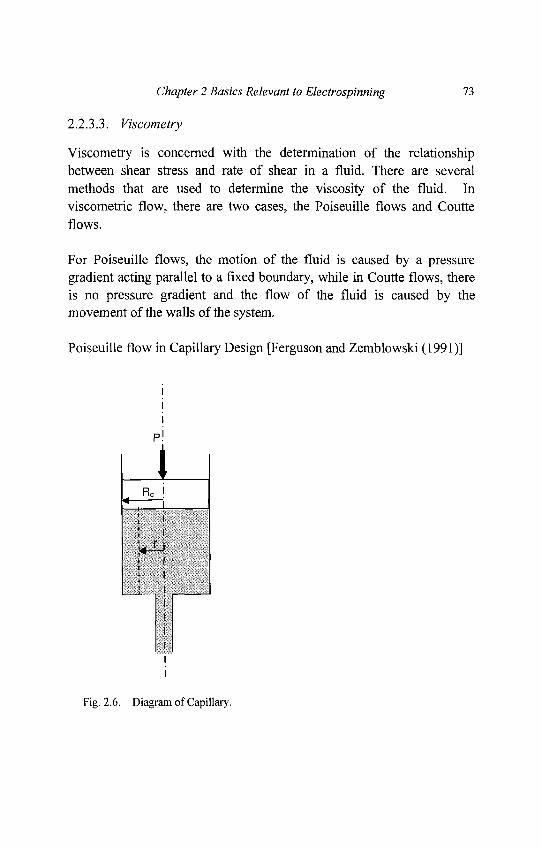
Chapter 2 Basics Relevant to Electrospinning 73
2.2.3.3. Viscometry
Viscometry is concerned with the determination of the relationshipbetween shear stress and rate of shear in a fluid. There are severalmethods that are used to determine the viscosity of the fluid. Inviscometric flow, there are two cases, the Poiseuille flows and Coutteflows.
For Poiseuille flows, the motion of the fluid is caused by a pressuregradient acting parallel to a fixed boundary, while in Coutte flows, thereis no pressure gradient and the flow of the fluid is caused by themovement of the walls of the system.
Poiseuille flow in Capillary Design [Ferguson and Zemblowski (1991)]
Fig. 2.6. Diagram of Capillary.
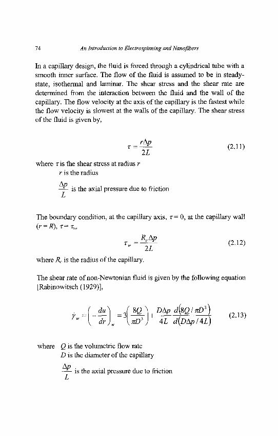
74 An Introduction to Electrospinning and Nanofibers
In a capillary design, the fluid is forced through a cylindrical tube with asmooth inner surface. The flow of the fluid is assumed to be in steady-state, isothermal and laminar. The shear stress and the shear rate aredetermined from the interaction between the fluid and the wall of thecapillary. The flow velocity at the axis of the capillary is the fastest whilethe flow velocity is slowest at the walls of the capillary. The shear stressof the fluid is given by,
r = ^ (2.11)2Z
where r is the shear stress at radius rr is the radius
is the axial pressure due to friction
The boundary condition, at the capillary axis, r = 0, at the capillary wall(r = R), T= TW,
where Rc is the radius of the capillary.
The shear rate of non-Newtonian fluid is given by the following equation[Rabinowitsch (1929)],
t J-*L) ./j^VgApdte/.P1) (2,3)' " I dr)w \nD') 4i rf(DAp/4i)
where Q is the volumetric flow rateD is the diameter of the capillary
is the axial pressure due to friction
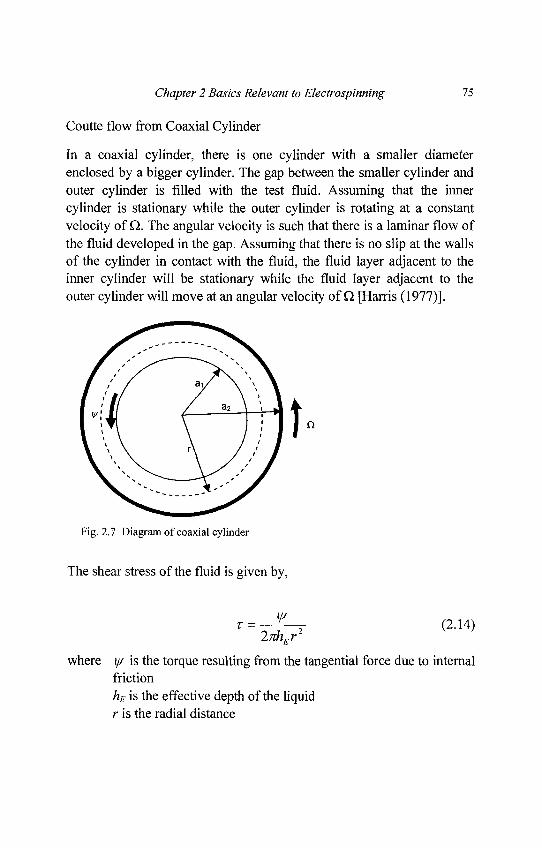
Chapter 2 Basics Relevant to Electrospinning 75
Coutte flow from Coaxial Cylinder
In a coaxial cylinder, there is one cylinder with a smaller diameterenclosed by a bigger cylinder. The gap between the smaller cylinder andouter cylinder is filled with the test fluid. Assuming that the innercylinder is stationary while the outer cylinder is rotating at a constantvelocity of Q. The angular velocity is such that there is a laminar flow ofthe fluid developed in the gap. Assuming that there is no slip at the wallsof the cylinder in contact with the fluid, the fluid layer adjacent to theinner cylinder will be stationary while the fluid layer adjacent to theouter cylinder will move at an angular velocity of Q [Harris (1977)].
Fig. 2.7 Diagram of coaxial cylinder
The shear stress of the fluid is given by,
2nhEr
where y/ is the torque resulting from the tangential force due to internalfrictionhE is the effective depth of the liquidr is the radial distance
76 An Introduction to Electrospinning and Nanofibers
The boundary condition, at the wall of the inner cylinder, z(a/) = r,, atthe wall of the outer cylinder, r(a2) = r2, therefore,
r,=-^T 0.13)
*2=~-Y (2-16)2nhEa2
For the shear rate of non-Newtonian fluids if the ratio of the outer toinner cylinder radius, S < 1.2, then [Krieger and Maron (1954); Fergusonand Zemblowski (1991)],
X / x2 d\— - l |
s2 { [ [
where the constants,
^ ^ ^ ( l + flnS)1 ^ 2 V 3 /
S"2 - 1
6 5 2
n " is the slope of a logarithmic plot of torque vs rotational speedN
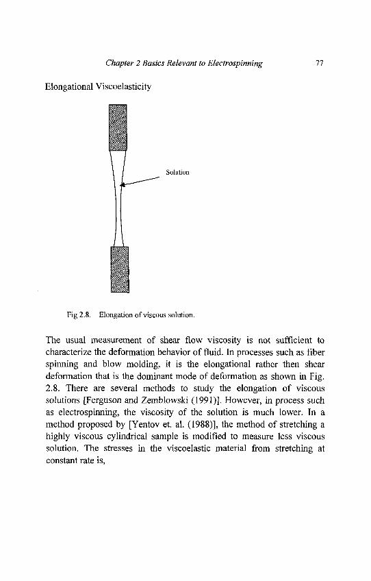
Chapter 2 Basics Relevant to Electrospinning 77
Elongational Viscoelasticity
Fig 2.8. Elongation of viscous solution.
The usual measurement of shear flow viscosity is not sufficient tocharacterize the deformation behavior of fluid. In processes such as fiberspinning and blow molding, it is the elongational rather then sheardeformation that is the dominant mode of deformation as shown in Fig.2.8. There are several methods to study the elongation of viscoussolutions [Ferguson and Zemblowski (1991)]. However, in process suchas electrospinning, the viscosity of the solution is much lower. In amethod proposed by [Yentov et. al. (1988)], the method of stretching ahighly viscous cylindrical sample is modified to measure less viscoussolution. The stresses in the viscoelastic material from stretching atconstant rate is,
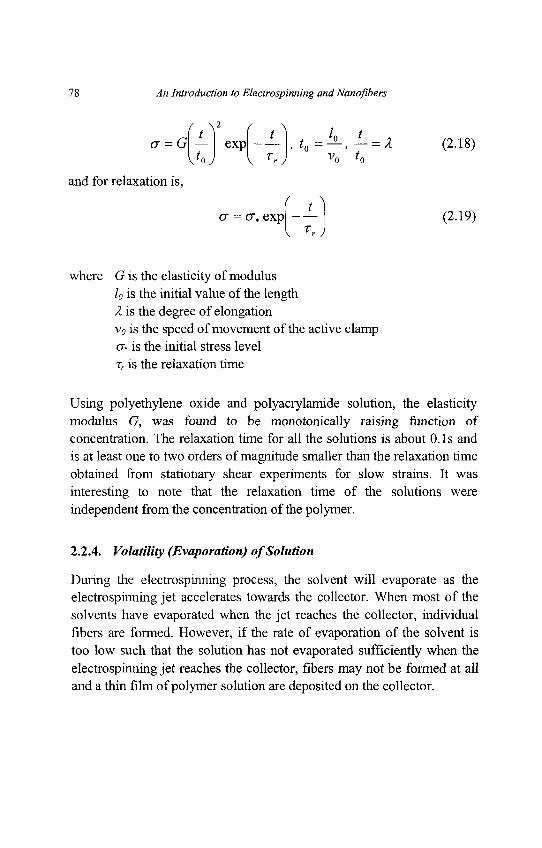
78 An Introduction to Electrospinning and Nanoflbers
* = G ( - ) e x p f - - l t0 = 4 L , - = X (2.18)
and for relaxation is,
<r = 0\, exp (2.19)
where G is the elasticity of moduluslo is the initial value of the lengthX is the degree of elongationv0 is the speed of movement of the active clamp<J» is the initial stress levelxr is the relaxation time
Using polyethylene oxide and polyacrylamide solution, the elasticitymodulus G, was found to be monotonically raising function ofconcentration. The relaxation time for all the solutions is about 0.1s andis at least one to two orders of magnitude smaller than the relaxation timeobtained from stationary shear experiments for slow strains. It wasinteresting to note that the relaxation time of the solutions wereindependent from the concentration of the polymer.
2.2.4. Volatility (Evaporation) of Solution
During the electrospinning process, the solvent will evaporate as theelectrospinning jet accelerates towards the collector. When most of thesolvents have evaporated when the jet reaches the collector, individualfibers are formed. However, if the rate of evaporation of the solvent istoo low such that the solution has not evaporated sufficiently when theelectrospinning jet reaches the collector, fibers may not be formed at alland a thin film of polymer solution are deposited on the collector.
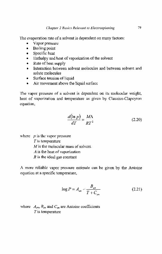
Chapter 2 Basics Relevant to Electrospinning 79
The evaporation rate of a solvent is dependent on many factors:• Vapor pressure• Boiling point• Specific heat• Enthalpy and heat of vaporization of the solvent• Rate of heat supply• Interaction between solvent molecules and between solvent and
solute molecules• Surface tension of liquid• Air movement above the liquid surface
The vapor pressure of a solvent is dependent on its molecular weight,heat of vaporization and temperature as given by Clausius-Clapeyronequation,
«=i« (2.20)dT RT2
where p is the vapor pressureT is temperatureM is the molecular mass of solventA is the heat of vaporizationR is the ideal gas constant
A more reliable vapor pressure estimate can be given by the Antoineequation at a specific temperature,
\ogP = A a n - - ^ r - (2.21)
where Aan, Ban and Can are Antoine coefficientsT is temperature
80 An Introduction to Electrospinning and Nanofibers
Boiling point of solvent, heat of vaporization and enthalpy are allaffected by the molecular weight of the solvent molecules. Due to thecomplex function of the evaporation mechanism, experimental methodsare used to determine the volatility of the solution.
2.2.5. Conductivity of Solution
For electrospinning process to be initiated, the solution must gainsufficient charges such that the repulsive forces within the solution areable to overcome the surface tension of the solution. Subsequentstretching or drawing of the electrospinning jet is also dependent on theability of the solution to carry charges.
Generally, the electric conductivity of solvents is very low (typicallybetween 10"3 to 10~9 o h m ' W ) as they contain very few free ions, if any,which are responsible for the electric conductivity of solution. Thepresence of acids, bases, salts and dissolved carbon dioxide may increasethe conductivity of the solvent. The electrical conductivity of the solventcan be increased significantly through mixing chemically non-interactingcomponents. Substances that can be added to the solvent to increase itsconductivity includes mineral salts, mineral acids, carboxylic acids, somecomplexes of acids with amines, stannous chloride and sometetraalkylammonium salts. For organic acid solvents, the addition of asmall amount of water will also greatly increase its conductivity due toionization of the solvent molecules.
There is another solution behavior known as the leaky dielectric whichdeals with poorly conducting liquids [Allan et. al. (1962)]. For aconducting liquid such as strong electrolytes, all the neutral species willdissociate fully to give free ions. However, for a leaky dielectric, thereare both a forward reaction where positive and negative ions areproduced from the dissociation of neutral species as well as arecombination reaction where the ions recombines to form back theneutral species.
Chapter 2 Basics Relevant to Electrospinning 81
Unlike perfect conductors or dielectrics where the electric stress isperpendicular to the interface and the alterations of the interface shapetogether with the interface tension balance the electric stress, free chargeaccumulated at the interface of a leaky dielectric and modifies the field.A subsequent viscous flow is induced to provide the stress to balance thetangential components of the field acting on the interface charge. Theelectric stresses produced by the conduction of the charges to theinterface are different from those of the perfect dielectrics or perfectconductors. Leaky dielectric model is generally derived from Stokesequation to describe the fluid motion and the Ohmic conductivity todescribe the conservation of current [Saville (1997)].
2.3. Electrostatics
Electrospinning is possible only if there is a potential difference betweenthe solution and the collector. Very often, an external electric field isused to control the charged electrospinning jet. Factors that affect theability of the solution to carry charges, the electric field that surroundsthe electrospinning jet and the dissipation of charges on the polymerfibers that are deposited on the collector will have an impact on theelectrospinning process.
In order to understand electric field and electrostatic, one has to startfrom the most fundamental unit, charge. In an atom, there exist protonsand electrons with the protons located inside the nucleus and electronsoutside it. The charge of a proton is positive while that of the electron isnegative. This is the smallest existing amount of charge and is measuredin the unit of coulomb, C where 1 coulomb is defined as 1ampere.second, and the electron charge, e, is given by,
e = -1.608.10~19C
The proton charge has the same numerical value but have a positivecharge instead. Therefore, if a body has excess electrons, it is negativelycharged while a deficit of electrons will give it a positive charge.
82 An Introduction to Electrospinning and Nanoflbers
2.3.1. Electric Field
The region where there is an electric force caused by the presence ofelectric charges is known as an electric field. The force can either beattraction between opposite charges or repulsion between charges of thesame polarity and is given by the Coulomb's Law,
F = gift (2.22)4nspd
2
where q is the chargesp is the absolute permittivity of the space between the chargesd is the distance between the charges
However, this law is only valid if the charges involved are point charges.In most practical cases, the electric field is more widely used and it isdefined as a region where a charge feels a force created by other charges.The magnitude of the field is given by its field strength.
F = qE (2.23)
where F is the forceq is the chargeE is the electric field strength
For a positive charge, the force has the same direction as the fieldstrength while a negative charge will have the force at the oppositedirection.
Given a charge q, the field strength at a distance d is written as,
£ = - ^ — (2.24)Aned
where s is the permittivity of the material
Chapter 2 Basics Relevant to Electrospinning 83
2.3.2. Potential Difference and Electric Field Representations
The potential of a point in space is given by the work required for acharge to move a test charge infinitely slowly from a reference point tothis point. Thus the potential can be given by,
O = ^ (2.25)dQ
The voltage between two points in space equal to the potential differencebetween them and is given by,
Ul2=O2-O{ (2.26)
When there are just two point charges, it is easy to describe theinteraction between them using the Coulomb's law. However, whenmore charges are involved, it will be advantages to use electric field andpotential to describe their interactions. While it is possible to usevectorial representation of the electric field, it is more common to usefield lines instead. The direction of the electric field along any point onthe field line is given by the tangent to the field line at that pointalthough the field direction is indicated by arrows on the field lines. Thefield lines always begin at the positive charges and end at the negativecharges as shown in Fig. 2.9.
Another way to represent the electric field is by a descriptive geometricquantity called an equipotential surface. Equipotential surfaces are usedto link all the points in space of the same potential with one another. Thefield lines at all the points must be perpendicular to the equipotentialsurfaces.
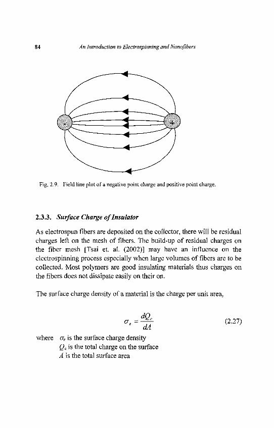
84 An Introduction to Electrospinning and Nanoflbers
Fig. 2.9. Field line plot of a negative point charge and positive point charge.
2.3.3. Surface Charge of Insulator
As electrospun fibers are deposited on the collector, there will be residualcharges left on the mesh of fibers. The build-up of residual charges onthe fiber mesh [Tsai et. al. (2002)] may have an influence on theelectrospinning process especially when large volumes of fibers are to becollected. Most polymers are good insulating materials thus charges onthe fibers does not dissipate easily on their on.
The surface charge density of a material is the charge per unit area,
*.=%• (2.27)dA
where ae is the surface charge densityQc is the total charge on the surfaceA is the total surface area
Chapter 2 Basics Relevant to Electrospinning 85
The total charge on any surface is therefore given by,
Qc = \credA (2.28)A
For an insulating material, the surface potentials will usually vary frompoint to point. Since the point potential at the interior of the insulatingmaterial is unknown, it is not possible to determine the voltage on theinsulating materials as a whole.
When a charge is introduced to an insulator, the charge will create a fieldboth on the surface of the insulator as well as its interior. The resultantfield will cause the individual charges to move due to mutual repulsionsuch that equilibrium is reached where the resulting force on any chargeis zero. The charges in the interior of the insulator will move to thesurface such that the field in any point inside the insulator is zero. Thecharge on the surface will orientate itself on the surface until the field isperpendicular to the surface. Therefore, charge will accumulate and thefield will be strongest around sharp point or protrusions of the surface.
2.3.4. FieldIonization
In electrospinning, the force that causes the stretching of the solution isdue to the repulsive forces between the charges on the electrospinningjet. Thus the presence of ions that neutralizes the charges during theelectrospinning process would have an impact on it [Fong et. al. (1999)].Under atmospheric condition using plane electrodes, an electric field ofabout 3xlO6V/m is required for electrons freed by natural radioactiveionization to ionize molecules of the air. The freed ions will then ionizeother air molecules in the region where the field strength is high enough.It must be emphasized that ionization depends on high field strength andnot high voltage. Also, the discharge condition for positive and negativevoltage is different. Generally, the positive voltage required forionization is 30% higher than negative voltage.
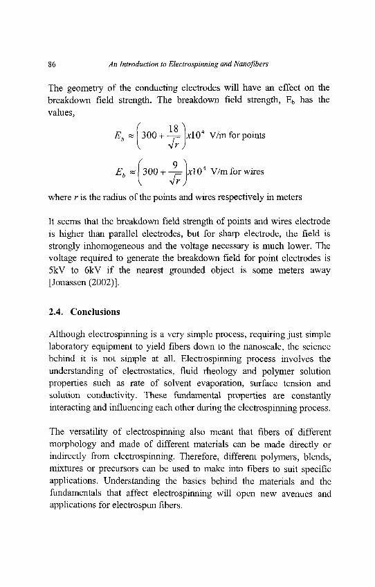
86 An Introduction to Electrospinning and Nanofibers
The geometry of the conducting electrodes will have an effect on thebreakdown field strength. The breakdown field strength, Eb has thevalues,
( 18^1Eb»\300 + -F xlO4 V/m for points
V <r)( 9 1̂
Eb « 300 + -j= \xl 04 V/m for wires
where r is the radius of the points and wires respectively in meters
It seems that the breakdown field strength of points and wires electrodeis higher than parallel electrodes, but for sharp electrode, the field isstrongly inhomogeneous and the voltage necessary is much lower. Thevoltage required to generate the breakdown field for point electrodes is5kV to 6kV if the nearest grounded object is some meters away[Jonassen (2002)].
2.4. Conclusions
Although electrospinning is a very simple process, requiring just simplelaboratory equipment to yield fibers down to the nanoscale, the sciencebehind it is not simple at all. Electrospinning process involves theunderstanding of electrostatics, fluid rheology and polymer solutionproperties such as rate of solvent evaporation, surface tension andsolution conductivity. These fundamental properties are constantlyinteracting and influencing each other during the electrospinning process.
The versatility of electrospinning also meant that fibers of differentmorphology and made of different materials can be made directly orindirectly from electrospinning. Therefore, different polymers, blends,mixtures or precursors can be used to make into fibers to suit specificapplications. Understanding the basics behind the materials and thefundamentals that affect electrospinning will open new avenues andapplications for electrospun fibers.
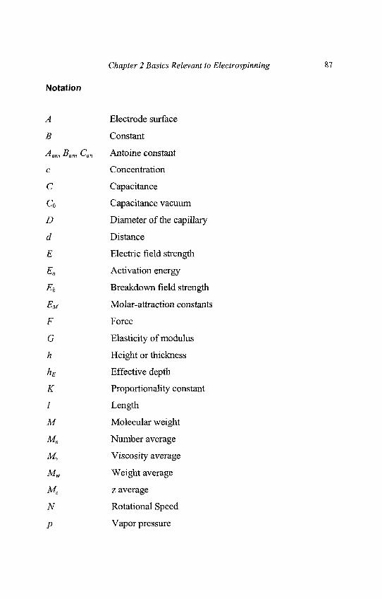
Chapter 2 Basics Relevant to Electrospinning 87
Notation
A Electrode surface
B Constant
Aan, Ban, Can Antoine constant
c Concentration
C Capacitance
Co Capacitance vacuum
D Diameter of the capillary
d Distance
E Electric field strength
Ea Activation energy
Eb Breakdown field strength
EM Molar-attraction constants
F Force
G Elasticity of modulus
h Height or thickness
hE Effective depth
K Proportionality constant
/ Length
M Molecular weight
Mn Number average
Mv Viscosity average
Mw Weight average
Mz z average
N Rotational Speed
p Vapor pressure
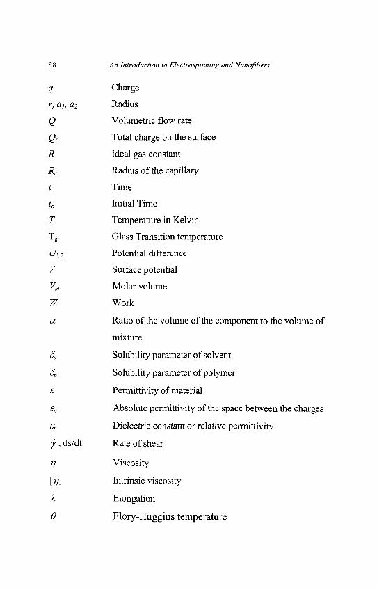
88 An Introduction to Electrospinning and Nanofibers
q Charge
r, ah a2 Radius
Q Volumetric flow rate
Qc Total charge on the surface
R Ideal gas constant
Rc Radius of the capillary.
t Time
to Initial Time
T Temperature in Kelvin
Tg Glass Transition temperature
U)}2 Potential difference
V Surface potential
Vm Molar volume
W Work
a Ratio of the volume of the component to the volume of
mixture
Ss Solubility parameter of solvent
8P Solubility parameter of polymer
s Permittivity of material
sp Absolute permittivity of the space between the charges
sr Dielectric constant or relative permittivity
y, ds/dt Rate of shear
TJ Viscosity
[ 77] Intrinsic viscosity
X Elongation
0 Flory-Huggins temperature
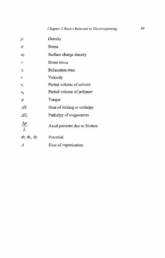
Chapter 2 Basics Relevant to Electrospinning 89
p Density
a Stress
ae Surface charge density
T Shear stress
tr Relaxation time
v Velocity
vs Partial volume of solvent
vp Partial volume of polymer
y/ Torque
AH Heat of mixing or enthalpy
AHV Enthalpy of evaporation
-*— Axial pressure due to friction
O, 0i, 02 Potential
A Heat of vaporization
Chapter 3
Electrospinning Process
In electrospinning, a high voltage is applied to a polymer fluid such thatcharges are induced within the fluid. When charges within the fluidreached a critical amount, a fluid jet will erupt from the droplet at the tipof the needle resulting in the formation of a Taylor cone. Theelectrospinning jet will travel towards the region of lower potential,which in most cases, is a grounded collector. There are many parametersthat will influence the morphology of the resultant electrospun fibers,from beaded fibers to fibers with pores on its surface. Althoughelectrospinning has been carried out on molten polymer [Lyons et. al.(2004); Larrondo and Manley (1981a); Larrondo and Manley (1981b);Larrondo and Manley (1981c)], most electrospinning are carried outusing polymer solution. Thus, the parameters affecting electrospinning ofpolymer solution is of greater interest and will be discussed in greaterdetails in this chapter. The parameters affecting electrospinning and thefibers may be broadly classified into polymer solution parameters,processing conditions which include the applied voltage, temperature andeffect of collector, and ambient conditions. With the understanding ofthese parameters, it is possible to come out with setups to yield fibrousstructures of various forms and arrangements. It is also possible to createnanofiber with different morphology by varying the parameters.
90
Chapter 3 Electrospinning Process 91
3.1. Polymer Solution Parameters
The properties of the polymer solution have the most significantinfluence in the electrospinning process and the resultant fibermorphology. The surface tension has a part to play in the formation ofbeads along the fiber length. The viscosity of the solution and itselectrical properties will determine the extent of elongation of thesolution. This will in turn have an effect on the diameter of the resultantelectrospun fibers.
3.1.1. Molecular Weight and Solution Viscosity
As mentioned in Chapter 2, one of the factors that affect the viscosity ofthe solution is the molecular weight of the polymer. Generally, when apolymer of higher molecular weight is dissolved in a solvent, itsviscosity will be higher than solution of the same polymer but of a lowermolecular weight. One of the conditions necessary for electrospinning tooccur where fibers are formed is that the solution must consists ofpolymer of sufficient molecular weight and the solution must be ofsufficient viscosity. As the jet leaves the needle tip duringelectrospinning, the polymer solution is stretched as it travels towards thecollection plate. During the stretching of the polymer solution, it is theentanglement of the molecule chains that prevents the electrically drivenjet from breaking up thus maintaining a continuous solution jet. As aresult, monomeric polymer solution does not form fibers whenelectrospun [Buchko et. al. (1999)].
The molecular weight of the polymer represents the length of thepolymer chain, which in turn have an effect on the viscosity of thesolution since the polymer length will determine the amount ofentanglement of the polymer chains in the solvent. Another way toincrease the viscosity of the solution is to increase the polymerconcentration. Similar to increasing the molecular weight, an increasedin the concentration will result in greater polymer chain entanglementswithin the solution which is necessary to maintain the continuity of thejet during electrospinning.
92 An Introduction to Electrospinning and Nanofibers
The polymer chain entanglements were found to have a significantimpact on whether the electrospinning jet breaks up into small dropletsor whether resultant electrospun fibers contain beads [Shenoy et. al.(2005)]. Although a minimum amount of polymer chain entanglementsand thus, viscosity is necessary for electrospinning, a viscosity that is toohigh will make it very difficult to pump the solution through the syringeneedle [Kameoka et. al. (2003)]. Moreover, when the viscosity is toohigh, the solution may dries at the tip of the needle beforeelectrospinning can be initiated [Zhong et. al. (2002)].
Many experiments have shown that a minimum viscosity for eachpolymer solution is required to yield fibers without beads [Megelski et.al. (2002); Fong et. al. (1999)]. At a low viscosity, it is common to findbeads along the fibers deposited on the collection plate. When theviscosity increases, there is a gradual change in the shape of the beadsfrom spherical to spindle-like until a smooth fiber is obtained [Fong et.al. (1999); Mit-uppatham et. al. (2004)] as shown in Fig. 3.1. At a lowerviscosity, the higher amount of solvent molecules and fewer chainentanglements will mean that surface tension has a dominant influencealong the electrospinning jet causing beads to form along the fiber. Whenthe viscosity is increased which means that there is a higher amount ofpolymer chains entanglement in the solution, the charges on theelectrospinning jet will be able to fully stretch the solution with thesolvent molecules distributed among the polymer chains. With increasedviscosity, the diameter of the fiber also increases [Baumgarten (1971);Jarusuwannapoom et. al. (2005); Demir et. al. (2002); Deitzel et. al.(2001b); Megelski et. al. (2002)]. This is probably due to the greaterresistance of the solution to be stretched by the charges on the jet[Jarusuwannapoom et. al. (2005)]. Table 3.1 shows the effect ofconcentration on beads formation.
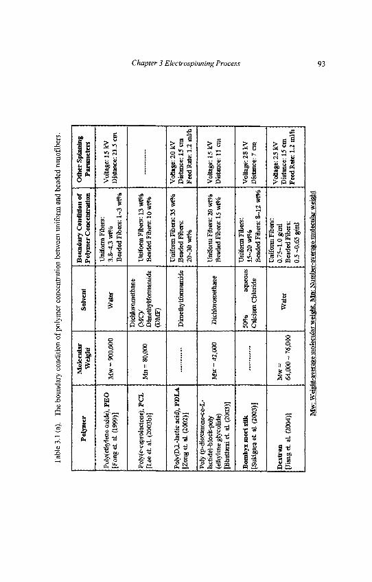
Tab
le 3
.1 (
a).
The
bou
ndar
y co
ndit
ion
of p
olym
er c
once
ntra
tion
bet
wee
n un
ifor
m a
nd b
eade
d na
nofi
bers
.
Pol
ymer
Pol
yeth
ylen
e ox
ide)
, P
EO
[Fon
g et
al.
(199
9)]
Poly
(e-c
apro
lact
one)
, PC
JL[L
ee e
t. at
. (20
03b)
)
Poly
(DX
-Jac
tic a
cid)
, PC
1A[Z
ong
et a
l. (2
002)
]
Poly
(p-
diox
anon
e-co
-L-
]act
ide)
-blo
ck-p
oly
(eth
ylen
e gl
yeol
ide)
JBha
ttara
i et
. al
(200
3)]
Bom
byx
mor
i si
lk[S
ukig
ara
et a
l. (2
003)
]
Dex
tran
[Jia
ng e
t. al
. (20
04)]
Mol
ecul
arW
eigh
t
Mw
= 9
00,0
00
Mn
= 8
0,00
0
Mw
= 4
2,00
0
Mw
=64
,000
~ 7
6,00
0
Solv
ent
Wat
er
Dic
hlor
omet
hane
(Mcy
Dim
ethy
lfoi
mam
ide
(DM
F)
Dta
efhy
lfot
rnam
ide
Die
hlor
onie
than
e
50%
aq
ueou
sC
alci
um C
hlor
ide
Wat
er
Bou
ndar
y C
ondi
tion
ofP
olym
er C
once
ntra
tion
Uni
form
Fib
ers:
3.8-
4.3
wt%
Bea
ded
Fibe
rs: 1
~3 w
t%
Uni
form
Fib
ers:
13
vim
Bea
ded
Fibe
rs: 1
0 w
t%
Uni
form
Fib
ers:
35
wt%
Bea
ded
Fibe
rs:
20~3
0 w
t%
Uni
form
Fib
ers:
20
wt%
Bea
ded
Fibe
rs: 1
5 w
t%
Uni
form
Fib
ers:
15-2
0 w
t%B
eade
d Fi
bers
: 8-4
2 w
tS'o
Uni
form
Fib
ers:
0,75
-1.0
g/m
lB
eade
d Fi
bers
:0.
5 ~0
.65
g/m
l
Oth
er S
pinn
ing
Par
amet
ers
Vol
tage
: 15
kVD
ista
nce:
21.
5 cm
Vol
tage
: 20
kVD
ista
nce:
15
cmFe
ed R
ate:
1.2
ml/h
Vol
tage
: 15
kVD
ista
nce:
11
cm
Vol
tage
: 28
kVD
ista
nce:
7 c
m
Vol
tage
: 25
kVD
ista
nce:
15
cmFe
ed R
ate:
1.2
ml/h
Mw
: Wei
ght-
aver
age
mol
ecul
ar w
eigh
t M
n: N
umbe
r-av
erag
e m
olec
ular
wei
ght
Chapter 3 Electrospinning Process 93
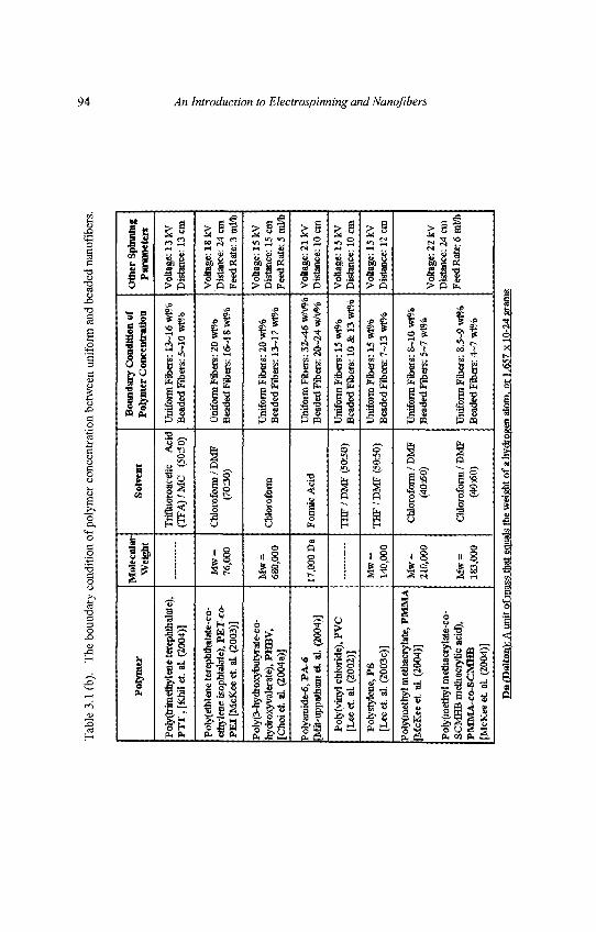
Tab
le 3
.1 (
b).
The
bou
ndar
y co
ndi t
ion
of p
olym
er c
once
ntra
t ion
bet
wee
n un
ifor
m a
nd b
eade
d na
nofi
bers
.
Poly
mer
Poly
(trim
ethy
Une
tere
phth
alat
e),
PT
T ,
[Khi
l et
al. (
2004
)]
Poly
(eth
lene
tere
phth
aiat
e-co
-et
hyle
ne is
ophi
alat
e), P
ET
-co-
PE
I [M
cKee
et.
al. (
2003
)]
Poly
(3-n
ydro
xybu
Jyra
te-c
o-hy
drox
yval
erat
e), P
HB
V,
[Cho
i et
aL (2
004a
)]
Pory
amid
e-6,
VA
-6M
il-up
pam
am e
t al
. (20
04)]
Poly
(vin
yl c
hlor
ide)
, PV
C[L
ee e
t al
(20
02)]
Poly
styl
ene,
PS
[Lee
et
al. (
2003
c)]
Poly
(met
hyl m
etha
cryl
ate,
PM
MA
[McK
ee e
t aL
(200
4)]
Poly
(met
hyl m
etha
cryl
ate-
co-
SCM
HB
met
hacr
ylic
aci
d),
PMM
A-C
O-S
CM
HB
[McK
ee e
t. al
. (20
04)]
Mol
ecul
arW
eigh
t
Mw
=76
,000
Mw
=68
0,00
0
17,0
00 D
a
Mw
=14
0,00
0
Mw
=21
0,00
0
Mw
=18
3,00
0
Solv
ent
Trif
luor
oace
tic
Aci
d(T
FA
)/M
C
(505
0)
Chl
orof
orai
/ D
MF
(703
0)
Chl
orof
orm
Form
ic A
cid
TH
F/D
MF
(50:
50)
TH
F/ D
MF
(50:
50)
Chl
orof
orm
/ D
MF
(40:
60)
Chl
orof
orm
/ D
MF
(40:
60)
Bou
ndar
y C
ondi
tion
ofPo
lym
er C
once
ntra
tion
Uni
form
Fib
ers:
13~
16 w
Bi
Bea
ded
Fibe
rs: 5
-10
wt%
Uni
form
Fib
ers:
20
wt%
Bea
ded
Fibe
rs: 1
6~18
wr%
Uni
form
Fib
ers:
20
w»'
oB
eade
d Fi
bers
: 13-
17 w
f%
Uni
form
Fib
ers:
32~
46 w
/vS*
Bea
ded
Fibe
rs: 2
0~24
w/v
%
Uni
form
Fib
ers:
15
w»b
Bea
ded
Fibe
rs: 1
0 &
13
wt%
Uni
form
Fib
ers:
15
wt%
Bea
ded
Fibe
rs: 7
-13
wlM
Uni
form
Fib
ers:
8~1
0 w
t%B
eade
d Fi
bers
: 5~7
wt%
Uni
form
Fib
ers:
8.5
-9 w
t%B
eade
d Fi
bers
: 4~7
v/F
/o
Oth
er S
pinn
ing
Para
met
ers
Vol
tage
: 13
kVD
ista
nce:
13
cm
Vol
tage
: 18
kVD
ista
nce:
24
cmFe
ed R
ate:
3 m
l/h
Vol
tage
: 15
kVD
ista
nce:
15
cmFe
ed R
ate:
5 n
il*
Vol
tage
: 21
kVD
ista
nce:
10
cm
Vol
tage
: 15
kVD
ista
nce:
10
cm
Vol
tage
: 15
kVD
ista
nce:
12
cm
Vol
tage
: 22
kVD
ista
nce:
24
cmFe
edR
ate:
6mM
i
Da(
Dal
tonV
. A u
nit o
f mas
s th
at e
qual
s th
e w
eigh
t of
a hy
drog
en a
tom
, or 1
.657
x 1
0-24
gra
ms
94 An Introduction to Electrospinning and Nanofibers
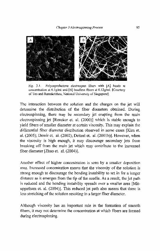
Chapter 3 Electrospinning Process 95
Fig. 3.1. Polycaprolactone electrospun fibers with [A] beads atconcentration at O.lg/ml and [B] beadless fibers at 0.12g/ml. [Courtesyof Teo and Ramakrishna, National University of Singapore].
The interaction between the solution and the charges on the jet willdetermine the distribution of the fiber diameters obtained. Duringelectrospinning, there may be secondary jet erupting from the mainelectrospinning jet [Reneker et. al. (2000)] which is stable enough toyield fibers of smaller diameter at certain viscosity. This may explain thedifferential fiber diameter distribution observed in some cases [Kim et.al. (2005); Demir et. al. (2002); Deitzel et. al. (2001b)]. However, whenthe viscosity is high enough, it may discourage secondary jets frombreaking off from the main jet which may contribute to the increasedfiber diameter [Zhao et. al. (2004)].
Another effect of higher concentration is seen by a smaller depositionarea. Increased concentration means that the viscosity of the solution isstrong enough to discourage the bending instability to set in for a longerdistance as it emerges from the tip of the needle. As a result, the jet pathis reduced and the bending instability spreads over a smaller area [Mit-uppatham et. al. (2004)]. This reduced jet path also means that there isless stretching of the solution resulting in a larger fiber diameter.
Although viscosity has an important role in the formation of smoothfibers, it may not determine the concentration at which fibers are formedduring electrospinning.
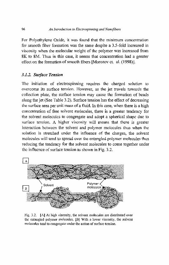
96 An Introduction to Electrospinning and Nanofibers
For Polyethylene Oxide, it was found that the minimum concentrationfor smooth fiber formation was the same despite a 3.5-fold increased inviscosity when the molecular weight of the polymer was increased from8K to 8M. Thus in this case, it seems that concentration had a greatereffect on the formation of smooth fibers [Morozov et. al. (1998)].
3.1.2. Surface Tension
The initiation of electrospinning requires the charged solution toovercome its surface tension. However, as the jet travels towards thecollection plate, the surface tension may cause the formation of beadsalong the jet (See Table 3.2). Surface tension has the effect of decreasingthe surface area per unit mass of a fluid. In this case, when there is a highconcentration of free solvent molecules, there is a greater tendency forthe solvent molecules to congregate and adopt a spherical shape due tosurface tension. A higher viscosity will means that there is greaterinteraction between the solvent and polymer molecules thus when thesolution is stretched under the influence of the charges, the solventmolecules will tend to spread over the entangled polymer molecules thusreducing the tendency for the solvent molecules to come together underthe influence of surface tension as shown in Fig. 3.2.
Fig. 3.2. [A] At high viscosity, the solvent molecules are distributed overthe entangled polymer molecules. [B] With a lower viscosity, the solventmolecules tend to congregate under the action of surface tension.
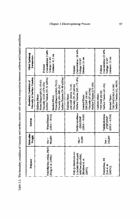
Tab
le 3
.2.
The
bou
ndar
y co
nditi
on o
f vis
cosi
ty a
nd s
urfa
ce te
nsio
n w
ith s
olve
nt c
ompo
sitio
n be
twee
n un
iform
and
bea
ded
nano
fiber
s.
Pol
ymer
Poly
(etta
ylen
e ox
ide)
, PE
O[F
onge
t. al
. (19
99)]
Poly
(p-
diox
anon
e-co
-L
-lact
ide)
-blo
ck-p
oIy
(eth
ylen
e gl
ycol
ide)
,[B
hatta
rai e
t. al
.(2
003)
]
Poly
styl
ene,
PS
[Lee
et. a
L(2
003c
)]
Mol
ecul
arW
eigh
t
Mw
=90
0,00
0
Mw
=42
,000
Mw
=14
0,00
0
Solv
ent
Wat
er/E
than
ol(1
00:0
-59:
41)
Dic
hlor
omet
hane
(DM
)/DM
F(1
00:0
~ 4
0:60
)
Tet
rahy
drof
uran
(TH
F)/D
MF
(100
:0 ~
0:1
00)
Bou
ndar
y C
ondi
tion
ofV
isco
sity
& S
urfa
ce T
ensi
on
Uni
form
Fib
ers:
Wat
er:E
than
ol (
69:3
1-59
:41)
Vis
cosi
ty (
1129
-117
9 cP
s)Su
rfac
e T
ensi
on (
55-5
1 m
N/m
)
Bea
ded
Fibe
rs:
Wat
er£t
hano
l (1
00:0
-79:
21)
Vis
cosi
ty (
402~
889
cPs)
Surf
ace
Ten
sion
(76
-60
mN
/m)
Uni
form
Fib
ers:
DM
:DM
F (1
00:0
, 75:
25)
Vis
cosi
ty (
39,3
5 m
N/m
)Su
rfac
e T
ensi
on (
125,
175
cPs)
Bea
ded
Fibe
rs:
DM
:DM
F (4
0:60
)V
isco
sity
(37
mN
/m)
Surf
ace
Ten
sion
(170
cPs
)
Uni
form
Fib
ers:
TH
F:D
MF
(50:
50)
Surf
ace
Ten
sion
(45
cPs)
Bea
ded
Fibe
rs:
TH
FDM
F(10
0«, 0
:100
)Su
rfac
e T
ensi
on (
42,4
8cPs
)
Oth
er S
pinn
ing
Par
amet
ers
Poly
mer
Con
cent
ratio
n: 3
wt%
Vol
tage
: 11
kVD
ista
nce:
21.
5 cm
Poly
mer
Con
cent
ratio
n.: 2
0 w
t%V
olta
ge: 1
5 kV
Dis
tanc
e: 1
1 cm
Poly
mer
Con
cent
ratio
n: 1
3 w
t%V
olta
ge: 1
5 kV
Dis
tanc
e: 1
2 cm
Chapter 3 Electrospinning Process 97
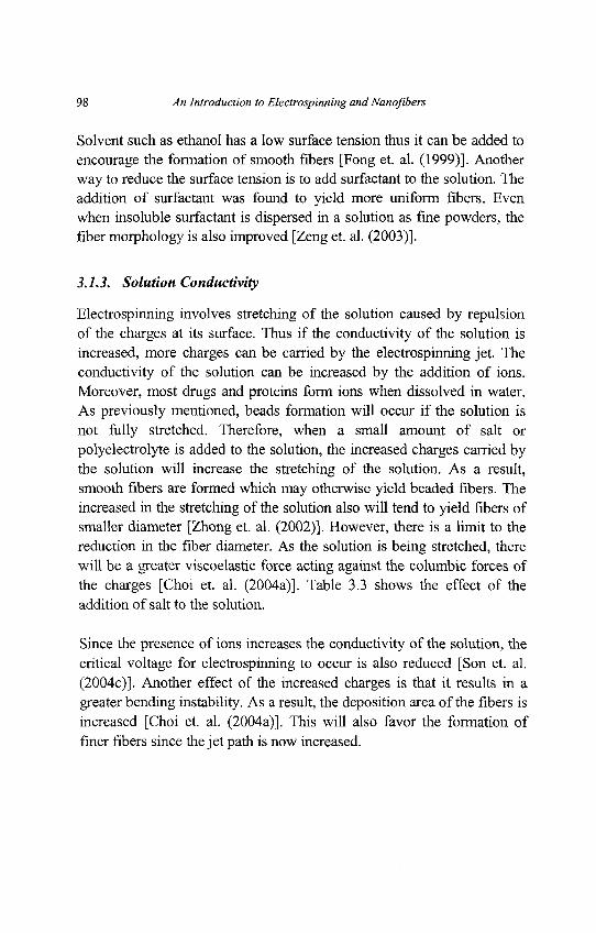
98 An Introduction to Electrospinning and Nanofibers
Solvent such as ethanol has a low surface tension thus it can be added toencourage the formation of smooth fibers [Fong et. al. (1999)]. Anotherway to reduce the surface tension is to add surfactant to the solution. Theaddition of surfactant was found to yield more uniform fibers. Evenwhen insoluble surfactant is dispersed in a solution as fine powders, thefiber morphology is also improved [Zeng et. al. (2003)].
3.1.3. Solution Conductivity
Electrospinning involves stretching of the solution caused by repulsionof the charges at its surface. Thus if the conductivity of the solution isincreased, more charges can be carried by the electrospinning jet. Theconductivity of the solution can be increased by the addition of ions.Moreover, most drugs and proteins form ions when dissolved in water.As previously mentioned, beads formation will occur if the solution isnot fully stretched. Therefore, when a small amount of salt orpolyelectrolyte is added to the solution, the increased charges carried bythe solution will increase the stretching of the solution. As a result,smooth fibers are formed which may otherwise yield beaded fibers. Theincreased in the stretching of the solution also will tend to yield fibers ofsmaller diameter [Zhong et. al. (2002)]. However, there is a limit to thereduction in the fiber diameter. As the solution is being stretched, therewill be a greater viscoelastic force acting against the columbic forces ofthe charges [Choi et. al. (2004a)]. Table 3.3 shows the effect of theaddition of salt to the solution.
Since the presence of ions increases the conductivity of the solution, thecritical voltage for electrospinning to occur is also reduced [Son et. al.(2004c)]. Another effect of the increased charges is that it results in agreater bending instability. As a result, the deposition area of the fibers isincreased [Choi et. al. (2004a)]. This will also favor the formation offiner fibers since the jet path is now increased.
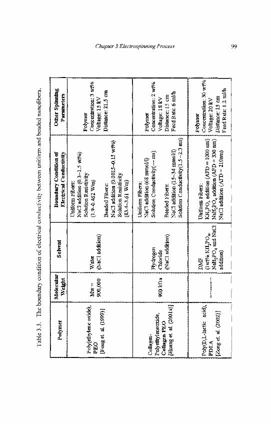
Tab
le 3
.3.
The
bou
ndar
y co
ndi t
ion
of e
lect
rica
l co
nduc
t ivi
ty b
etw
een
unif
orm
and
bea
ded
nano
fibe
rs.
Poly
mer
Pol
yeth
ylen
e ox
ide)
,PE
O[F
onge
t. al
. (19
99)]
Col
lage
n -
Poly
ethy
lene
oxid
e,C
oUag
en-P
EO
[Hua
ng e
t. al
. (20
01a)
]
Poly
(D,L
-lact
ic
acid
),PD
LA
[Zon
get.
al. (
2002
)]
Mol
ecul
arW
eigh
t
Mw
=90
0,00
0
900
kD a
Solv
ent
Wat
er(N
aCl a
dditi
on)
Hyd
roge
nC
hlor
ide
(NaC
l ad
ditio
n)
DM
F(l
wt%
KH
-jPO
^N
aH3P
O4
and
NaC
lad
ditio
n)
Bou
ndar
y C
ondi
tion
ofE
lect
rica
l Con
duct
ivity
Uni
form
Fib
ers:
NaC
l add
ition
(0.
3-1.
5 w
t%)
Solu
tion
Res
istiv
ity(1
.9-0
.462
Wm
)
Bea
ded
Fibe
rs:
NaC
l add
ition
(0.
0015
-0.1
5 w
t%)
Solu
tion
Res
istiv
ity(8
3.4-
3.61
Wm
)
Uni
form
Fib
ers:
NaC
l add
ition
(68
mm
ol/l)
Solu
tion
Con
duct
ivity
(— m
s)
Bea
ded
Fibe
rs:
NaC
l add
ition
(15
-34
mm
ol/l)
Solu
tion
Con
duct
ivity
(1.5
-2.
3 m
s)
Uni
form
Fib
ers:
KH
2PO
4 add
ition
(A
FD =
100
0 nm
)N
aH2P
O4
addi
tion
(AFD
= 3
30 n
m)
NaC
l add
ition
(A
FD =
210
nm)
Oth
er S
pinn
ing
Par
amet
ers
Poly
mer
Con
cent
ratio
n: 3
viW
aV
olta
ge: 1
5 kV
Dis
tanc
e: 2
1.5
cm
Poly
mer
Con
cent
ratio
n: 2
wt%
Vol
tage
: 18
kVD
ista
nce:
15
cmF
eedR
ate:
6ml/
h
Poly
mer
Con
cent
ratio
n: 3
0 w
t%V
olta
ge: 2
0 kV
Dis
tanc
e: 1
5 cm
Feed
Rat
e: 1
.2 m
l/h
Chapter 3 Electrospinning Process 99
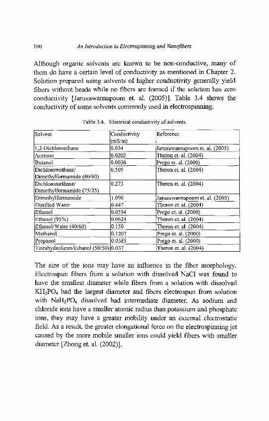
100 An Introduction to Electrospinning and Nanoflbers
Although organic solvents are known to be non-conductive, many ofthem do have a certain level of conductivity as mentioned in Chapter 2.Solution prepared using solvents of higher conductivity generally yieldfibers without beads while no fibers are formed if the solution has zeroconductivity [Jarusuwannapoom et. al. (2005)]. Table 3.4 shows theconductivity of some solvents commonly used in electrospinning.
Table 3.4. Electrical conductivity of solvents.
Solvent Conductivity Reference(mS/m)
1,2-Dichloroethane 0.034 Jarusuwannapoom et. al. (2005)Acetone 0.0202 Theron et. al. (2004)Butanol 0.0036 Prego et. al. (2000)Dichloromethane/ 0.505 Theron et. al. (2004)Dimethylformamide (40/60)Dichloromethane/ 0.273 Theron et. al. (2004)Dimethylformamide (75/25)Dimethylformamide 1.090 Jarusuwannapoom et. al. (2005)Distilled Water 0.447 Theron et. al. (2004)Ethanol 0.0554 Prego et. al. (2000)Ethanol (95%) 0.0624 Theron et. al. (2004)Ethanol/Water (40/60) 0.150 Theron et. al. (2004)Methanol 0.1207 Prego et. al. (2000)Propanol 0.0385 Prego et. al. (2000)Tetrahydrofuran/Ethanol (50/50) |o.O37 ^heron et. al. (2004)
The size of the ions may have an influence in the fiber morphology.Electrospun fibers from a solution with dissolved NaCl was found tohave the smallest diameter while fibers from a solution with dissolvedKH2PO4 had the largest diameter and fibers electrospun from solutionwith NaH2PO4 dissolved had intermediate diameter. As sodium andchloride ions have a smaller atomic radius than potassium and phosphateions, they may have a greater mobility under an external electrostaticfield. As a result, the greater elongational force on the electrospinning jetcaused by the more mobile smaller ions could yield fibers with smallerdiameter [Zhong et. al. (2002)].
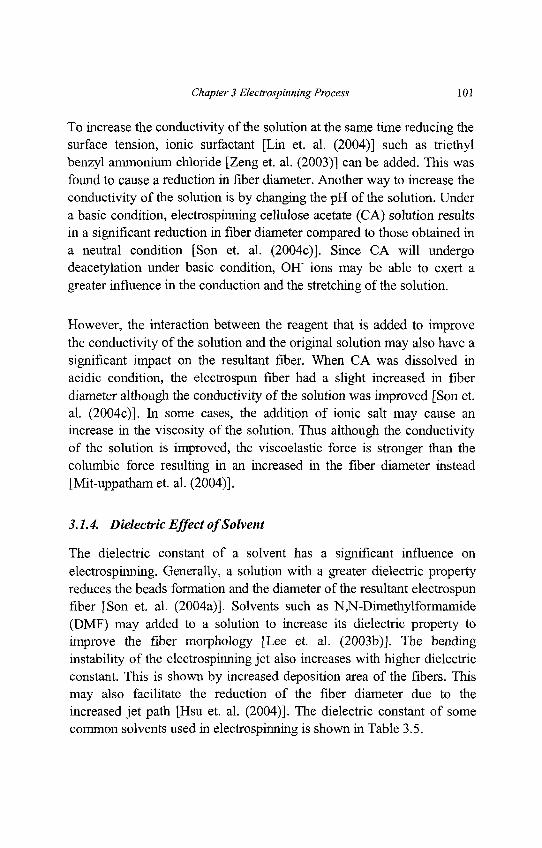
Chapter 3 Electrospinning Process 101
To increase the conductivity of the solution at the same time reducing thesurface tension, ionic surfactant [Lin et. al. (2004)] such as triethylbenzyl ammonium chloride [Zeng et. al. (2003)] can be added. This wasfound to cause a reduction in fiber diameter. Another way to increase theconductivity of the solution is by changing the pH of the solution. Undera basic condition, electrospinning cellulose acetate (CA) solution resultsin a significant reduction in fiber diameter compared to those obtained ina neutral condition [Son et. al. (2004c)]. Since CA will undergodeacetylation under basic condition, OH' ions may be able to exert agreater influence in the conduction and the stretching of the solution.
However, the interaction between the reagent that is added to improvethe conductivity of the solution and the original solution may also have asignificant impact on the resultant fiber. When CA was dissolved inacidic condition, the electrospun fiber had a slight increased in fiberdiameter although the conductivity of the solution was improved [Son et.al. (2004c)]. In some cases, the addition of ionic salt may cause anincrease in the viscosity of the solution. Thus although the conductivityof the solution is improved, the viscoelastic force is stronger than thecolumbic force resulting in an increased in the fiber diameter instead[Mit-uppatham et. al. (2004)].
3.1.4. Dielectric Effect of Solvent
The dielectric constant of a solvent has a significant influence onelectrospinning. Generally, a solution with a greater dielectric propertyreduces the beads formation and the diameter of the resultant electrospunfiber [Son et. al. (2004a)]. Solvents such as N,N-Dimethylformamide(DMF) may added to a solution to increase its dielectric property toimprove the fiber morphology [Lee et. al. (2003b)]. The bendinginstability of the electrospinning jet also increases with higher dielectricconstant. This is shown by increased deposition area of the fibers. Thismay also facilitate the reduction of the fiber diameter due to theincreased jet path [Hsu et. al. (2004)]. The dielectric constant of somecommon solvents used in electrospinning is shown in Table 3.5.
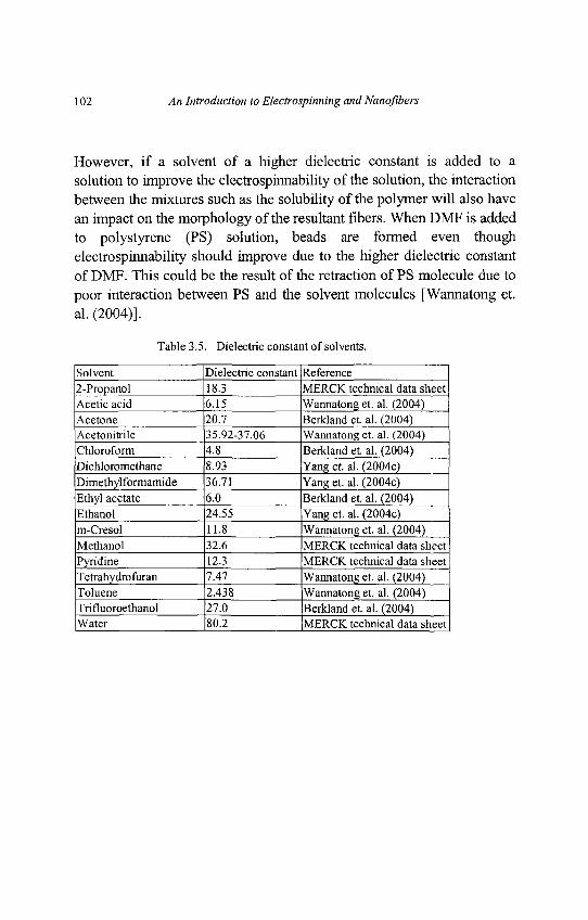
102 An Introduction to Electrospinning and Nanofibers
However, if a solvent of a higher dielectric constant is added to a
solution to improve the electrospinnability of the solution, the interaction
between the mixtures such as the solubility of the polymer will also have
an impact on the morphology of the resultant fibers. When DMF is added
to polystyrene (PS) solution, beads are formed even though
electrospinnability should improve due to the higher dielectric constant
of DMF. This could be the result of the retraction of PS molecule due to
poor interaction between PS and the solvent molecules [Wannatong et.
al. (2004)].
Table 3.5. Dielectric constant of solvents.
Solvent Dielectric constant Reference2-Propanol 183 MERCK technical data sheetAcetic acid 6.15 Wannatong et. al. (2004)Acetone 207 Berkland et al. (2004)Acetonitrile 35.92-37.06 Wannatong et. al. (2004)Chloroform 4J5 Berkland et al. (2004)Dichloromethane 8JP3 Yang et. al. (2004c)Dimethylformamide 36.71 Yang et. al. (2004c)Ethyl acetate 6J) Berkland et al. (2004)Ethanol 24.55 Yang et. al. (2004c)m-Cresol UJ$ Wannatong et. al. (2004)Methanol 32j) MERCK technical data sheetPyridine 123 MERCK technical data sheetTetrahydrofuran 7A7 Wannatong et. al. (2004)Toluene 2.438 Wannatong et. al. (2004)Trifluoroethanol TL0 Berkland et al. (2004)Water [80.2 |MERCK technical data sheet
Chapter 3 Electrospinning Process 103
3.2. Processing Conditions
Another important parameter that affects the electrospinning process isthe various external factors exerting on the electrospinning jet. Thisincludes the voltage supplied, the feedrate, temperature of the solution,type of collector, diameter of needle and distance between the needle tipand collector. These parameters have a certain influence in the fibermorphology although they are less significant than the solutionparameters.
3.2.1. Voltage
A crucial element in electrospinning is the application of a high voltageto the solution.. The high voltage will induce the necessary charges onthe solution and together with the external electric field, will initiate theelectrospinning process when the electrostatic force in the solutionovercomes the surface tension of the solution. Generally, both highnegative or positive voltage of more than 6kV is able to cause thesolution drop at the tip of the needle to distort into the shape of a TaylorCone during jet initiation [Taylor (1964)]. Depending on the feedrate ofthe solution, a higher voltage may be required so that the Taylor Cone isstable. The columbic repulsive force in the jet will then stretch theviscoelastic solution. If the applied voltage is higher, the greater amountof charges will cause the jet to accelerate faster and more volume ofsolution will be drawn from the tip of the needle. This may result in asmaller and less stable Taylor Cone [Zhong et. al. (2002)]. When thedrawing of the solution to the collection plate is faster than the supplyfrom the source, the Taylor Cone may recede into the needle [Deitzel et.al. (2001b)].
104 An Introduction to Electrospinning and Nanofibers
As both the voltage supplied and the resultant electric field have aninfluence in the stretching and the acceleration of the jet, they will havean influence on the morphology of the fibers obtained. In most cases, ahigher voltage will lead to greater stretching of the solution due to thegreater columbic forces in the jet as well as the stronger electric field.These have the effect of reducing the diameter of the fibers [Lee et. al.(2004); Buchko et. al. (1999); Megelski et. al. (2002)] and alsoencourage faster solvent evaporation to yield drier fibers [Pawlowski et.al. (2005)]. When a solution of lower viscosity is used, a higher voltagemay favor the formation of secondary jets during electrospinning. Thishas the effect of reducing the fiber diameter [Demir et. al. (2002)].Another factor that may influence the diameter of the fiber is the flighttime of the electrospinning jet. A longer flight time will allow more timefor the fibers to stretch and elongates before it is deposited on thecollection plate. Thus, at a lower voltage, the reduced acceleration of thejet and the weaker electric field may increase the flight time of theelectrospinning jet which may favor the formation of finer fibers. In thiscase, a voltage close to the critical voltage for electrospinning may befavorable to obtain finer fibers [Zhao et. al. (2004)].
At a higher voltage, it was found that there is a greater tendency forbeads formation [Deitzel et. al. (2001b); Demir et. al. (2002); Zhong et.al. (2002)]. It was also reported that the shape of the beads changes fromspindle-like to spherical-like with increasing voltage [Zhong et. al.(2002)]. Given the increased stretching of the jet due to higher voltage,there should be less beads formation as reported in some cases[Jarusuwannapoom et. al. (2005)] as shown in Fig. 3.3. The increased inbeads density due to increased voltage may be the result of increasedinstability of the jet as the Taylor Cone recedes into the syringe needle[Deitzel et. al. (2001b); Zhong et. al. (2002)]. In an interestingobservation, [Krishnappa et. al. (2003)] reported that increasing voltagewill increased the beads density, which at an even higher voltage, thebeads will join to form a thicker diameter fiber.
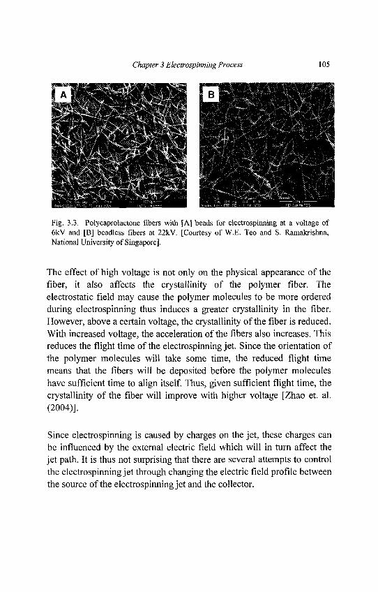
Chapter 3 Electrospinning Process 105
Fig. 3.3. Polycaprolactone fibers with [A] beads for electrospinning at a voltage of6kV and [B] beadless fibers at 22kV. [Courtesy of W.E. Teo and S. Ramakrishna,National University of Singapore].
The effect of high voltage is not only on the physical appearance of thefiber, it also affects the crystallinity of the polymer fiber. Theelectrostatic field may cause the polymer molecules to be more orderedduring electrospinning thus induces a greater crystallinity in the fiber.However, above a certain voltage, the crystallinity of the fiber is reduced.With increased voltage, the acceleration of the fibers also increases. Thisreduces the flight time of the electrospinning jet. Since the orientation ofthe polymer molecules will take some time, the reduced flight timemeans that the fibers will be deposited before the polymer moleculeshave sufficient time to align itself. Thus, given sufficient flight time, thecrystallinity of the fiber will improve with higher voltage [Zhao et. al.(2004)].
Since electrospinning is caused by charges on the jet, these charges canbe influenced by the external electric field which will in turn affect thejet path. It is thus not surprising that there are several attempts to controlthe electrospinning jet through changing the electric field profile betweenthe source of the electrospinning jet and the collector.
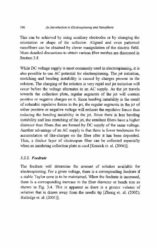
106 An Introduction to Electrospinning and Nanofibers
This can be achieved by using auxiliary electrodes or by changing theorientation or shape of the collector. Aligned and even patternednanofibers can be obtained by clever manipulation of the electric field.More detailed discussions to obtain various fiber meshes are discussed inSection 3.8
While DC voltage supply is most commonly used in electrospinning, it isalso possible to use AC potential for electrospinning. The jet initiation,stretching and bending instability is caused by charges present in thesolution. The charging of the solution is very rapid and jet initiation willoccur before the voltage alternates in an AC supply. As the jet travelstowards the collection plate, regular segments of the jet will containpositive or negative charges on it. Since bending instability is the resultof columbic repulsive forces in the jet, the regular segments in the jet ofeither positive or negative voltage will reduces the repulsive forces thusreducing the bending instability in the jet. Since there is less bendinginstability and less stretching of the jet, the resultant fibers have a higherdiameter than fibers that are formed by DC supply of the same voltage.Another advantage of an AC supply is that there is fewer tendencies foraccumulation of like-charges on the fiber after it has been deposited.Thus, a thicker layer of electrospun fiber can be collected especiallywhen an insulating collection plate is used [Kessick et. al. (2004)].
3.2.2. Feedrate
The feedrate will determine the amount of solution available forelectrospinning. For a given voltage, there is a corresponding feedrate ifa stable Taylor cone is to be maintained. When the feedrate is increased,there is a corresponding increase in the fiber diameter or beads size asshown in Fig. 3.4. This is apparent as there is a greater volume ofsolution that is drawn away from the needle tip [Zhong et. al. (2002);Rutledge et. al. (2001)].
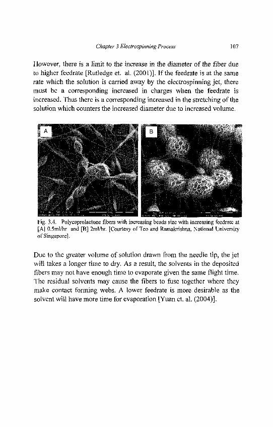
Chapter 3 Electrospinning Process 107
However, there is a limit to the increase in the diameter of the fiber dueto higher feedrate [Rutledge et. al. (2001)]. If the feedrate is at the samerate which the solution is carried away by the electrospinning jet, theremust be a corresponding increased in charges when the feedrate isincreased. Thus there is a corresponding increased in the stretching of thesolution which counters the increased diameter due to increased volume.
Fig. 3.4. Polycaprolactone fibers with increasing beads size with increasing feedrate at[A] 0.5ml/hr and [B] 2ml/hr. [Courtesy of Teo and Ramakrishna, National Universityof Singapore].
Due to the greater volume of solution drawn from the needle tip, the jetwill takes a longer time to dry. As a result, the solvents in the depositedfibers may not have enough time to evaporate given the same flight time.The residual solvents may cause the fibers to fuse together where theymake contact forming webs. A lower feedrate is more desirable as thesolvent will have more time for evaporation [Yuan et. al. (2004)].
108 An Introduction to Electrospinning and Nanofibers
3.2.3. Temperature
The temperature of the solution has both the effect of increasing itsevaporation rate and reducing the viscosity of the polymer solution.When polyurethane is electrospun at a higher temperature, the fibersproduced have a more uniform diameter [Demir et. al. (2002)]. This maybe due to the lower viscosity of the solution and greater solubility of thepolymer in the solvent which allows more even stretching of the solution.With a lower viscosity, the Columbic forces are able to exert a greaterstretching force on the solution thus resulting in fibers of smallerdiameter [Mit-uppatham et. al. (2004)]. Increased polymer moleculesmobility due to increased temperature also allows the Columbic force tostretch the solution further. However, in cases where biologicalsubstances such as enzymes and proteins are added to the solution forelectrospinning, the use of high temperature may cause the substance tolose its functionality.
3.2.4. Effect of Collector
There must be an electric field between the source and the collector forelectrospinning to initiate. Thus in most electrospinning setup, thecollector plate is made out of conductive material such as aluminum foilwhich is electrically grounded so that there is a stable potentialdifference between the source and the collector. In the case when a non-conducting material is used as a collector, charges on the electrospinningjet will quickly accumulates on the collector which will result in fewerfibers deposited [Kessick et. al. (2004); Liu and Hsieh (2002)]. Fibersthat are collected on the non-conducting material usually have a lowerpacking density compared to those collected on a conducting surface.This is caused by the repulsive forces of the accumulated charges on thecollector as more fibers are deposited. For a conducting collector,charges on the fibers are dissipated thus allowing more fibers to beattracted to the collector. The fibers are able to pack closely together as aresult [Liu and Hsieh (2002)].
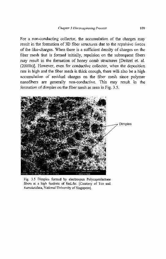
Chapter 3 Electrospinning Process 109
For a non-conducting collector, the accumulation of the charges mayresult in the formation of 3D fiber structures due to the repulsive forcesof the like-charges. When there is a sufficient density of charges on thefiber mesh that is formed initially, repulsion on the subsequent fibersmay result in the formation of honey comb structures [Deitzel et. al.(2001b)]. However, even for conductive collector, when the depositionrate is high and the fiber mesh is thick enough, there will also be a highaccumulation of residual charges on the fiber mesh since polymernanofibers are generally non-conductive. This may result in theformation of dimples on the fiber mesh as seen in Fig. 3.5.
Fig. 3.5 Dimples formed by electrospun Polycaprolactonefibers at a high feedrate of 8mL/hr. [Courtesy of Teo andRamakrishna, National University of Singapore],
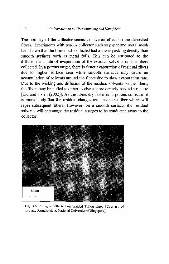
110 An Introduction to Electrospinning and Nanofibers
The porosity of the collector seems to have an effect on the depositedfibers. Experiments with porous collector such as paper and metal meshhad shown that the fiber mesh collected had a lower packing density thansmooth surfaces such as metal foils. This can be attributed to thediffusion and rate of evaporation of the residual solvents on the fiberscollected. In a porous target, there is faster evaporation of residual fibersdue to higher surface area while smooth surfaces may cause anaccumulation of solvents around the fibers due to slow evaporation rate.Due to the wicking and diffusion of the residual solvents on the fibers,the fibers may be pulled together to give a more densely packed structure[Liu and Hsieh (2002)]. As the fibers dry faster on a porous collector, itis more likely that the residual charges remain on the fiber which willrepel subsequent fibers. However, on a smooth surface, the residualsolvents will encourage the residual charges to be conducted away to thecollector.
Fig. 3.6 Collagen collected on braided Teflon sheet. [Courtesy ofTeo and Ramakrishna, National University of Singapore].
Chapter 3 Electrospinning Process 111
The texture of the fiber mesh may also be varied by using patternedcollector as shown in Fig. 3.6. The fibers are deposited on the braidedTeflon sheet and the resultant mesh has a topography that takes thepattern of the surface of the Teflon sheet.
Whether or not the collector is static or moving also have an effect on theelectrospinning process. While rotating collector has been used to collectaligned fibers, which is covered in more details in section 3.8, it wasfound to assist in yielding fibers that are dry. This is useful becausecertain solvents such as Dimethylformamide (DMF) which is good forelectrospinning but have a high boiling point that may result in the fibersbeing wet when they are collected. A rotating collector will give thesolvent more time to evaporate [Wannatong et. al. (2004)] and alsoincrease the rate of evaporation of the solvents on the fibers. This willimprove the morphology of the fiber where distinct fibers are required.
3.2.5. Diameter of Pipette Orifice / Needle
The internal diameter of the needle or the pipette orifice has a certaineffect on the electrospinning process. A smaller internal diameter wasfound to reduce the clogging as well as the amount of beads on theelectrospun fibers [Mo et. al. (2004)]. The reduction in the cloggingcould be due to less exposure of the solution to the atmosphere duringelectrospinning. Decrease in the internal diameter of the orifice was alsofound to cause a reduction in the diameter of the electrospun fibers.When the size of the droplet at the tip of the orifice is decreased, such asin the case of a smaller internal diameter of the orifice, the surfacetension of the droplet increases. For the same voltage supplied, a greatercolumbic force is required to cause jet initiation. As a result, theacceleration of the jet decreases and this allows more time for thesolution to be stretched and elongated before it is collected. However, ifthe diameter of the orifice is too small, it may not be possible to extrudea droplet of solution at the tip of the orifice [Zhao et. al. (2004)].
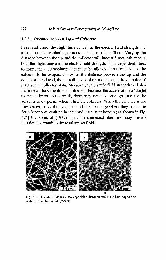
112 An Introduction to Electrospinning and Nanoflbers
3.2.6. Distance between Tip and Collector
In several cases, the flight time as well as the electric field strength willaffect the electrospinning process and the resultant fibers. Varying thedistance between the tip and the collector will have a direct influence inboth the flight time and the electric field strength. For independent fibersto form, the electrospinning jet must be allowed time for most of thesolvents to be evaporated. When the distance between the tip and thecollector is reduced, the jet will have a shorter distance to travel before itreaches the collector plate. Moreover, the electric field strength will alsoincrease at the same time and this will increase the acceleration of the jetto the collector. As a result, there may not have enough time for thesolvents to evaporate when it hits the collector. When the distance is toolow, excess solvent may cause the fibers to merge where they contact toform junctions resulting in inter and intra layer bonding as shown in Fig.3.7 [Buchko et. al. (1999)]. This interconnected fiber mesh may provideadditional strength to the resultant scaffold.
Fig. 3.7. Nylon 6,6 at (a) 2 cm deposition distance and (b) 0.5cm depositiondistance [Buchko et. al. (1999)].
Chapter 3 Electrospinning Process 113
Depending on the solution property, the effect of varying the distancemay or may not have a significant effect on the fiber morphology. Insome cases, changing the distance has no significant effect on the fiberdiameter. However, beads were observed to form when distance was toolow [Megelski et. al. (2002)]. The formation of beads may be the resultof increased field strength between the needle tip and the collector.Decreasing the distance has the same effect as increasing the voltagesupplied and this will cause an increased in the field strength. Asmentioned earlier, if the field strength is too high, the increasedinstability of the jet may encourage beads formation [Deitzel et. al.(2001b); Zhong et. al. (2002)]. However, if the distance is such that thefield strength is at an optimal value, there is less beads formed as theelectrostatic field provides sufficient stretching force to the jet[Jarusuwannapoom et. al. (2005)]. In other circumstances, increasing thedistance results in a decrease in the average fiber diameter [Ayutsede et.al. (2005)]. The longer distance means that there is a longer flight timefor the solution to be stretched before it is deposited on the collector[Zhao et. al. (2004); Reneker et. al. (2000)]. However, there are caseswhere at a longer distance, the fiber diameter increases. This is due to thedecrease in the electrostatic field strength resulting in less stretching ofthe fibers [Lee et. al. (2004)]. When the distance is too large, no fibersare deposited on the collector [Zhao et. al. (2004)]. Therefore, it seemsthat there is an optimal electrostatic field strength below which thestretching of the solution will decrease resulting in increased fiberdiameters.
3.3. Ambient Parameters
The effect of the electrospinning jet surrounding is one area which is stillpoorly investigated. Any interaction between the surrounding and thepolymer solution may have an effect on the electrospun fibermorphology. High humidity for example was found to cause theformation of pores on the surface of the fibers. Since electrospinning isinfluenced by external electric field, any changes in the electrospinningenvironment will also affect the electrospinning process.
114 An Introduction to Electrospinning and Nanofibers
3.3.1. Humidity
The humidity of the electrospinning environment may have an influencein the polymer solution during electrospinning. At high humidity, it islikely that water condenses on the surface of the fiber whenelectrospinning is carried out under normal atmosphere. As a result, thismay have an influence on the fiber morphology especially polymerdissolved in volatile solvents [Megelski et. al. (2002); Bognitzki et. al.(2001)]. Experiments using Polysulfone (PS) dissolved inTetrahydrofuran (THF) shows that at humidity of less than 50%, the fibersurfaces are smooth. However, an increased in the humidity duringelectrospinning will cause circular pores to form on the fiber surfaces.The sizes of the circular pores increases with increasing humidity untilthey coalescence to form large, non-uniform shaped structures as shownin Fig 3.8. The depth of the pore also increases with increasing humidityas determined by atomic force microscopy. However, above certainhumidity, the depth of pores, its diameter and numbers start to saturate[Casper et. al. (2004)].
In the study of thin films, formation of pores on the surface is attributedto breath figures [Srnivasarao et. al. (2001)]. This may also happenduring electrospinning as water vapor may condense on the surface ofthe jet due to cooling of the surface of the jet as a result of rapidevaporation of the volatile solvent. Pores are created when both waterand solvent eventually evaporates. Although pores formed on thin filmdue to breath figures are uniform, pores seen on electrospun fibers arenot and this may be due to the dynamic condition of the electrospinningjet as compared to static condition where the effects of breath figures areseen on thin films [Megelski et. al. (2002); Casper et. al. (2004)].
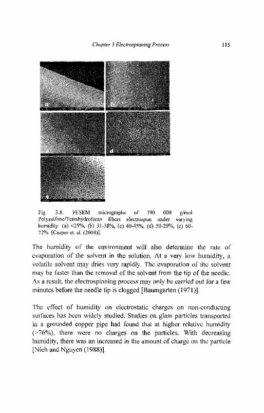
Chapter 3 Electrospinning Process 115
Fig. 3.8. FESEM micrographs of 190 000 g/molPolysulfone/Tetrahydrofuran fibers electrospun under varyinghumidity: (a) <25%, (b) 31-38%, (c) 40-45%, (d) 50-29%, (e) 60-72% [Casper et. al. (2004)].
The humidity of the environment will also determine the rate ofevaporation of the solvent in the solution. At a very low humidity, avolatile solvent may dries very rapidly. The evaporation of the solventmay be faster than the removal of the solvent from the tip of the needle.As a result, the electrospinning process may only be carried out for a fewminutes before the needle tip is clogged [Baumgarten (1971)].
The effect of humidity on electrostatic charges on non-conductingsurfaces has been widely studied. Studies on glass particles transportedin a grounded copper pipe had found that at higher relative humidity(>76%), there were no charges on the particles. With decreasinghumidity, there was an increased in the amount of charge on the particle[Nieh and Nguyen (1988)].
116 An Introduction to Electrospinning and Nanoflbers
It has also been suggested that the high humidity can help the dischargeof the electrospun fiber [Li and Xia (2004a); Li et. al. (2005a)].However, more tests have to be carried out to determine the effect ofhumidity on the electrical discharge during electrospinning and theaccumulation of residual charges on the collected fibers.
3.3.2. Type of Atmosphere
The composition of the air in the electrospinning environment will havean effect on the electrospinning process. Different gases have differentbehavior under high electrostatic field. For example, helium will breaksdown under high electrostatic field and thus electrospinning is notpossible. However, when a gas with higher breakdown voltage is usedsuch as Freon®-12, the fibers obtained have twice the diameter of thoseelectrospun in air given all other conditions equal [Baumgarten (1971)].
3.3.3. Pressure
Under enclosed condition, it is possible to investigate the effect ofpressure on the electrospinning jet. Generally, reduction in the pressuresurrounding the electrospinning jet does not improve the electrospinningprocess. When the pressure is below atmospheric pressure, the polymersolution in the syringe will have a greater tendency to flow out of theneedle and there causes unstable jet initiation. As the pressure decreases,rapid bubbling of the solution will occur at the needle tip. At very lowpressure, electrospinning is not possible due to direct discharge of theelectrical charges.
Chapter 3 Electrospinning Process 117
3.4. Melt-Electrospinning
Although polymer solutions are more often used in electrospinning, thereare also several investigations on electrospinning using polymer melts.Generally, most conditions that affect electrospinning of polymersolution are also applicable to electrospinning of molten polymer.Similar to electrospinning of polymer solution, polymers with highermolecular weight formed the largest diameter fibers. However, there aresome differences between electrospinning of polymer melts and polymersolution.
In polymer melt, there must be a constant heat supplied to the reservoircontaining the polymer solution for electrospinning so that the polymerwill remains in its molten state. The distance between the tip of theneedle and the collector for electrospinning of molten polymer isgenerally much closer (2cm) [Larrondo and Manley (1981); Lyons et. al.(2004)] than conventional electrospinning using polymer solution(>10cm). Depending on the temperature that maintains the polymer in itsmolten form, polymer melt is more viscous than polymer solution thus agreater charge is required for electrospinning jet initiation. Withincreasing field strength, it was found that the diameters of the resultantfibers were reduced [Lyons et. al. (2004)].
3.5. Creation of Different Nanofibers
Just by varying the parameters of electrospinning, it is possible to getsome variation in the morphology of the nanofibers. Several parametershave been linked to the formation of beaded fibers as covered in theearlier part of the chapter. However, other than beaded and non-beadedfibers, electrospinning is able to produce other types of fibers withinteresting morphology as well as different types of nanofibers.
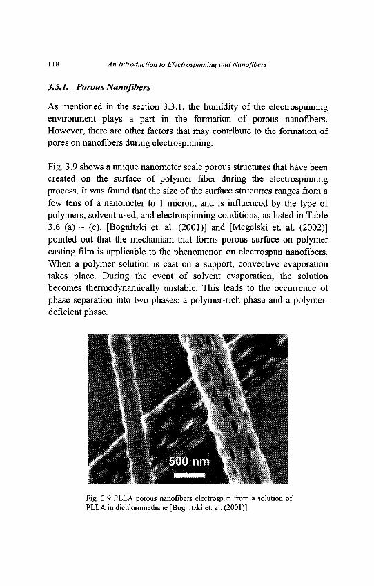
118 An Introduction to Electrospinning and Nanofibers
3.5.1. Porous Nanofibers
As mentioned in the section 3.3.1, the humidity of the electrospinningenvironment plays a part in the formation of porous nanofibers.However, there are other factors that may contribute to the formation ofpores on nanofibers during electrospinning.
Fig. 3.9 shows a unique nanometer scale porous structures that have beencreated on the surface of polymer fiber during the electrospinningprocess. It was found that the size of the surface structures ranges from afew tens of a nanometer to 1 micron, and is influenced by the type ofpolymers, solvent used, and electrospinning conditions, as listed in Table3.6 (a) ~ (c). [Bognitzki et. al. (2001)] and [Megelski et. al. (2002)]pointed out that the mechanism that forms porous surface on polymercasting film is applicable to the phenomenon on electrospun nanofibers.When a polymer solution is cast on a support, convective evaporationtakes place. During the event of solvent evaporation, the solutionbecomes thermodynamically unstable. This leads to the occurrence ofphase separation into two phases: a polymer-rich phase and a polymer-deficient phase.
Fig. 3.9 PLLA porous nanofibers electrospun from a solution ofPLLA in dichloromethane [Bognitzki et. al. (2001)].
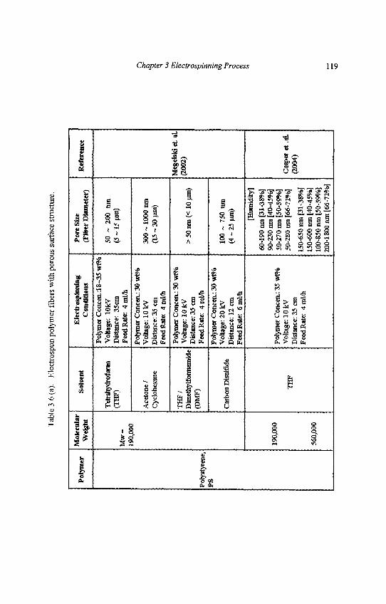
Tab
le 3
.6 (
a).
Ele
ctro
spun
pol
ymer
fib
ers
wi t
h po
rous
sur
face
str
uctu
re.
Pol
ymer
Poly
styr
ene,
PS
Mol
ecul
arW
dght
Mw
=19
0,00
0
190,
000
560,
000
Solv
ent
Tet
rahy
drof
uran
(TH
F)
Ace
tone
/C
yclo
hexa
ne
TH
F/
Dim
ethy
lfor
mam
ide
(DM
F)
Car
bon
Dis
ulfid
e
TH
F
Elc
ctro
spin
ntag
Con
diH
ons
Poly
mer
Con
eea
:18~
35 w
1%V
olta
ge:
lOkV
Dis
tanc
e: 3
5cm
Fee
d R
ate:
4nu
7h
Poly
mer
Con
cen.
: 30
wt%
Vol
tage
: 10
kv
Dis
tanc
e: 3
5 cm
Feed
Rat
e: 4
ml/
h
Poly
mer
Con
eea:
30
wt%
Vol
tage
: 10
kVD
ista
nce:
35
cmFe
ed R
ate:
A
mil
h
Poly
mer
Con
cen.
: 30
wt%
Vol
tage
: 20
kVD
ista
nce:
12
cmFe
ed R
ate:
6m
M»
Poly
mer
Con
cen.
: 35
wt%
Vol
tage
: 10
kVD
ista
nce:
35
cmFe
ed R
ate:
4m
l/h
Por
e Si
ze(F
iber
Dia
met
er)
50 ~
200
tu
n(5
~ 1
5 pa
n)
300
~ 10
00 ti
nt(1
5 ~
30 f
im)
> 5
0 te
n (<
10
jun)
100
~ 75
0 nm
(4-2
5 jjm
)
[Hum
idity
]
60-1
90 n
m [
31-3
8%]
90-2
30 n
m [
40-4
5%]
50-2
70 n
m [
50-5
9%]
50-2
80 n
m [
66-7
2%]
150-
650
nm [
31-3
8%]
150-
600
nm [
40-4
5%]
100-
850
nm [
50-5
9%]
200-
1800
nm
[66
-72%
]
Ref
eren
ce
Meg
elsk
i et
. al.
(200
2)
Caq
)«r
et .a
l.(2
004)
Chapter 3 Electrospinning Process 119
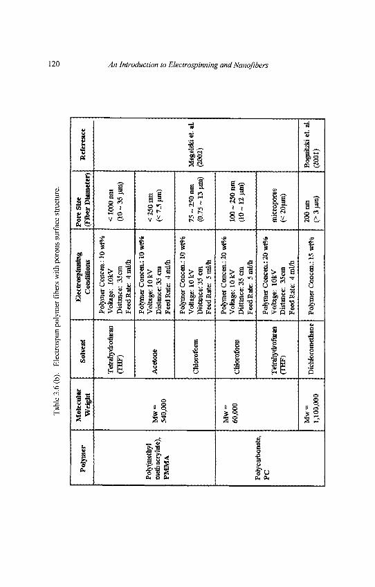
Tab
le 3
.6 (
b).
Ele
ctro
spun
pol
ymer
fib
ers
wit
h po
rous
sur
face
str
uctu
re.
Pol
ymer
Pory
(met
hyl
met
hacr
ylat
e),
PM
MA
Pol
ycar
bona
te,
PC
Mol
ecul
arW
eigh
t
Mw
=54
0,00
0
Mw
=60
,000
Mw
=1,
100,
000
Sol
vent
Tet
rahy
drof
uran
CIH
F)
Ace
tone
CW
orof
onn
Chl
orof
orm
Tet
rahy
dro&
ran
(TH
F)
Dic
hlor
omet
hane
Ele
ctro
spln
ning
Con
diti
ons
Poly
mer
Con
cen.
: 10
wt%
Vol
tage
: lO
kVD
ista
nce:
35c
mF
eed
Rat
e: 4
ml *
Poly
mer
Con
cern
.: 10
wPH
»V
olta
ge: 1
0 kV
Dis
tanc
e: 3
5 cm
Fee
d R
ate:
4m
l/h
Poly
mer
Con
cen.
: 10
wt%
Vol
tage
: 10
kVD
ista
nce:
35
cmFe
ed R
ate:
5 r
al/h
Poly
mer
Con
cen.
: 20
wt%
Vol
tage
: 10
kVD
ista
nce:
35
era
Fee
d R
ate:
5 r
al/h
Poly
mer
Con
cen.
: 20
w(%
Vol
tage
: lO
kVD
ista
nce:
35c
mF
eed
Rat
e:
4mU
h
Poly
mer
Con
cen.
: 15
wW
t
Por
e Si
ze(F
iber
Dia
met
er)
<1
00
0n
m(1
0 ~
35 t
un)
< 2
50 u
rn(<
7.5
(im
)
75 ~
250
nm
(0.7
5 ~
13 p
in)
100
~ 25
0 nm
(10
~ 12
nm
)
mic
ropo
res
(< 2
0fiin
)
200
nm(>
3 j
im)
Ref
eren
ce
Meg
elsk
i et.
al.
(200
2)
Bog
nitz
ki e
t. al
.(2
001)
120 An Introduction to Electrospinning and Nanofibers
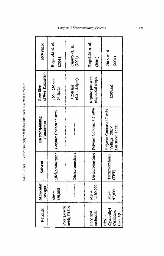
Tab
le 3
.6 (
c).
Ele
ctro
spun
pol
ymer
fibe
rs w
ith p
orou
s su
rfac
e st
ruct
ure.
Pol
ymer
Pofy
(L-la
ctic
acid
), P
LL
A
Poly
viny
lca
rboz
ole
Eth
yl-
Cya
noet
hyl
Cel
lulo
se,
(E-C
E)C
Mol
ecul
arW
efgl
rt
Mw
=15
0,00
0
Mw
=1,
100,
000
Mn
=97
,000
Solv
ent
Dic
hlor
omet
hane
Dic
hlor
omet
hane
Dic
hlor
omet
hane
Tet
rahy
drof
iiran
(TH
F)
Ele
ctro
spin
ning
Con
diti
ons
Poly
mer
Con
cen.
: 5 w
t%
Poly
mer
Con
ceit
: 7.5
wt%
Poly
mer
Con
cen.
: 17
wt%
Vol
tage
: 30
kVD
ista
nce:
15c
m
Por
e Si
ze(F
iber
Dia
met
er)
100
~ 25
0 nm
( <lp
m)
<25
0nm
(0.3
~ 3
.5fii
n)
Reg
ular
pits
with
ellip
soid
al s
hape
(200
mn)
Ref
eren
ce
Bog
nitz
ki e
t. al
.
(200
1)
Car
uso
et.
al.
(200
1)
Bog
nitz
ki e
t. al
.
(200
1)
Zha
o et
. al.
(200
4)
Chapter 3 Electrospinning Process 121
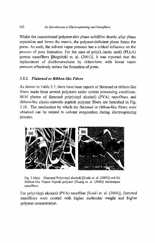
122 An Introduction to Electrospinning and Nanojibers
Whilst the concentrated polymer-rich phase solidifies shortly after phaseseparation and forms the matrix, the polymer-deficient phase forms thepores. As such, the solvent vapor pressure has a critical influence on theprocess of pore formation. For the case of poly(L-lactic acid) (PLLA)porous nanofibers [Bognitzki et. al. (2001)], it was reported that thereplacement of dichloromethane by chloroform with lower vaporpressure effectively reduce the formation of pores.
3.5.2. Flattened or Ribbon-like Fibers
As shown in Table 3.7, there have been reports of flattened or ribbon-likefibers made from several polymers under certain processing conditions.SEM photos of flattened poly(vinyl alcohol) (PVA) nanofibers andribbon-like elastic-mimetic peptide polymer fibers are furnished in Fig.3.10. The mechanism by which the flattened or ribbon-like fibers wereobtained can be related to solvent evaporation during electrospinningprocess.
Fig. 3.10(a). Flattened Poly(vinyl alcohol) [Koski et. al. (2005)] and (b)Ribbon-like Elastin Peptide polymer [Huang et. al. (2000)] electrospunnanofibers.
For poly(vinyl alcohol) (PVA) nanofiber [Koski et. al. (2004)], flattenednanofibers were created with higher molecular weight and higherpolymer concentration.
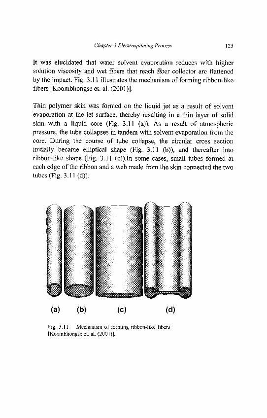
Chapter 3 Electrospinning Process 123
It was elucidated that water solvent evaporation reduces with highersolution viscosity and wet fibers that reach fiber collector are flattenedby the impact. Fig. 3.11 illustrates the mechanism of forming ribbon-likefibers [Koombhongse et. al. (2001)].
Thin polymer skin was formed on the liquid jet as a result of solventevaporation at the jet surface, thereby resulting in a thin layer of solidskin with a liquid core (Fig. 3.11 (a)). As a result of atmosphericpressure, the tube collapses in tandem with solvent evaporation from thecore. During the course of tube collapse, the circular cross sectioninitially became elliptical shape (Fig. 3.11 (b)), and thereafter intoribbon-like shape (Fig. 3.11 (c)).In some cases, small tubes formed ateach edge of the ribbon and a web made from the skin connected the twotubes (Fig. 3.11 (d)).
Fig. 3.11. Mechanism of forming ribbon-like fibers[Koombhongse et. al. (2001)1.
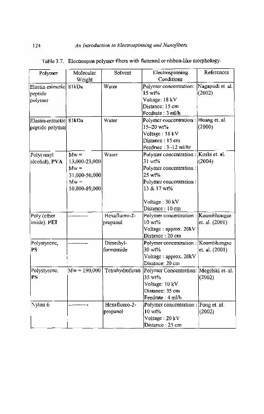
124 An Introduction to Electrospinning and Nanofibers
Table 3.7. Electrospun polymer fibers with flattened orribbon-like morphology.
Polymer Molecular Solvent Electrospinning ReferencesWeight Conditions
Elastin-mimetic 81kDa Water Polymer concentration: Nagapudi et. al.peptide 15 wt% (2002)polymer Voltage: 18 kV
Distance: 15 cmFeedrate : 3 ml/h
Elastin-mimetic 81kDa Water Polymer concentration : Huang et. al.peptide polymer 15-20 wt% (2000)
Voltage: 18 kVDistance : 15 cmFeedrate : 3—12 ml/hr
Poly(vinyl Mw = Water Polymer concentration : Koski et. al.alcohol), PVA 13,000-23,000 31 wt% (2004)
Mw = Polymer concentration :31,000-50,000 25wt%Mw = Polymer concentration :50,000-89,000 13 & 17 wt%
Voltage : 30 kVDistance : 10 cm
Poly (ether Hexafluoro-2- Polymer concentration: Koombhongseimide),PEI propanol 10wt% et. al. (2001)
Voltage : approx. 20kVDistance : 20 cm
Polystyrene, Dimethyl- Polymer concentration: KoombhongsePS formamide 30 wt% et. al. (2001)
Voltage : approx. 20kVDistance: 20 cm
Polystyrene, Mw= 190,000 Tetrahydrofuran Polymer Concentration: Megelski et. al.PS 35 wt% (2002)
Voltage: lOkVDistance: 35 cmFeedrate : 4 ml/h
Nylon 6 Hexafluoro-2- Polymer concentration : Fong et. al.propanol 10wt% (2002)
Voltage : 20 kVDistance : 25 cm
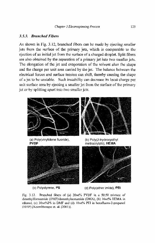
Chapter 3 Electrospinning Process 125
3.5.3. Branched Fibers
As shown in Fig. 3.12, branched fibers can be made by ejecting smallerjets from the surface of the primary jets, which is comparable to theejection of an initial jet from the surface of a charged droplet. Split fibersare also obtained by the separation of a primary jet into two smaller jets.The elongation of the jet and evaporation of the solvent alter the shapeand the charge per unit area carried by the jet. The balance between theelectrical forces and surface tension can shift, thereby causing the shapeof a jet to be unstable. Such instability can decrease its local charge perunit surface area by ejecting a smaller jet from the surface of the primaryjet or by splitting apart into two smaller jets.
Fig. 3.12. Branched fibers of (a) 20wt% PVDF in a 50:50 mixture ofdimethylformamide (DMF)/demethylacetamide (DMA), (b) 16wt% HEMA inethanol, (c) 30wt%PS in DMF and (d) 10wt% PEI in hexafluoro-2-propanol(HFIP) [Koombhongse et. al. (2001)1.
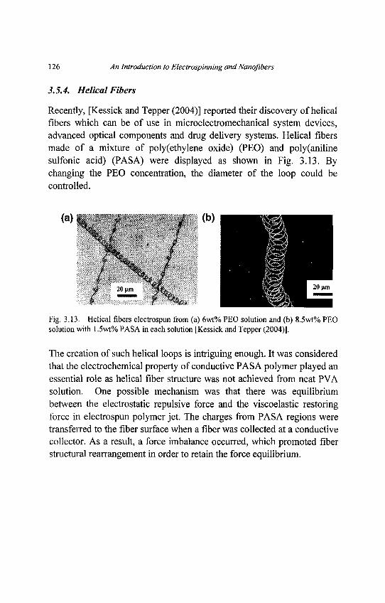
126 An Introduction to Electrospinning and Nanofibers
3.5.4. Helical Fibers
Recently, [Kessick and Tepper (2004)] reported their discovery of helicalfibers which can be of use in microelectromechanical system devices,advanced optical components and drug delivery systems. Helical fibersmade of a mixture of poly(ethylene oxide) (PEO) and poly(anilinesulfonic acid) (PASA) were displayed as shown in Fig. 3.13. Bychanging the PEO concentration, the diameter of the loop could becontrolled.
Fig. 3.13. Helical fibers electrospun from (a) 6wt% PEO solution and (b) 8.5wt% PEOsolution with 1.5wt% PASA in each solution [Kessick and Tepper (2004)].
The creation of such helical loops is intriguing enough. It was consideredthat the electrochemical property of conductive PASA polymer played anessential role as helical fiber structure was not achieved from neat PVAsolution. One possible mechanism was that there was equilibriumbetween the electrostatic repulsive force and the viscoelastic restoringforce in electrospun polymer jet. The charges from PASA regions weretransferred to the fiber surface when a fiber was collected at a conductivecollector. As a result, a force imbalance occurred, which promoted fiberstructural rearrangement in order to retain the force equilibrium.
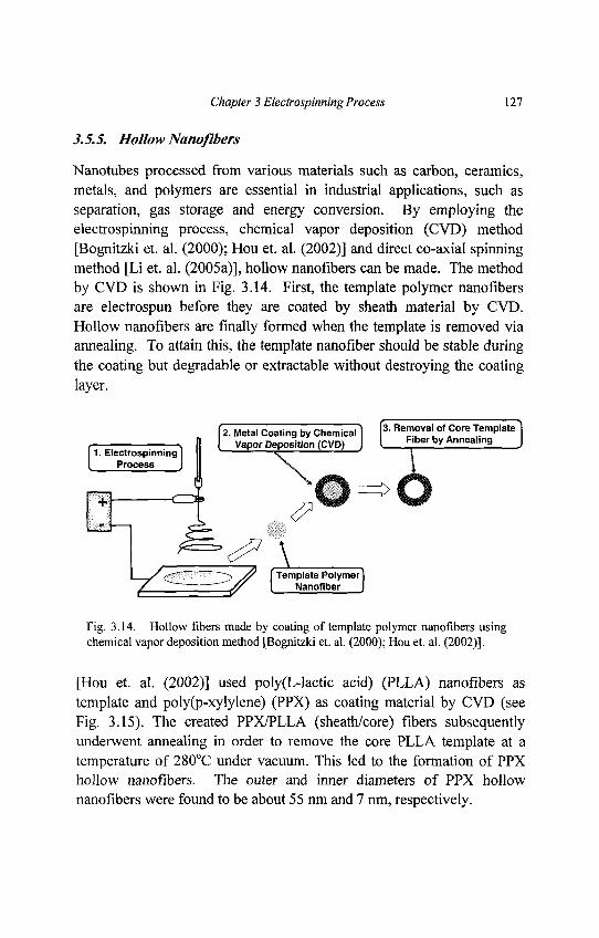
Chapter 3 Electrospinning Process 127
3.5.5. Hollow Nanofibers
Nanotubes processed from various materials such as carbon, ceramics,metals, and polymers are essential in industrial applications, such asseparation, gas storage and energy conversion. By employing theelectrospinning process, chemical vapor deposition (CVD) method[Bognitzki et. al. (2000); Hou et. al. (2002)] and direct co-axial spinningmethod [Li et. al. (2005a)], hollow nanofibers can be made. The methodby CVD is shown in Fig. 3.14. First, the template polymer nanofibersare electrospun before they are coated by sheath material by CVD.Hollow nanofibers are finally formed when the template is removed viaannealing. To attain this, the template nanofiber should be stable duringthe coating but degradable or extractable without destroying the coatinglayer.
Fig. 3.14. Hollow fibers made by coating of template polymer nanofibers usingchemical vapor deposition method [Bognitzki et. al. (2000); Hou et. al. (2002)].
[Hou et. al. (2002)] used poly(L-lactic acid) (PLLA) nanofibers astemplate and poly(p-xylylene) (PPX) as coating material by CVD (seeFig. 3.15). The created PPX/PLLA (sheath/core) fibers subsequentlyunderwent annealing in order to remove the core PLLA template at atemperature of 280°C under vacuum. This led to the formation of PPXhollow nanofibers. The outer and inner diameters of PPX hollownanofibers were found to be about 55 nm and 7 nm, respectively.
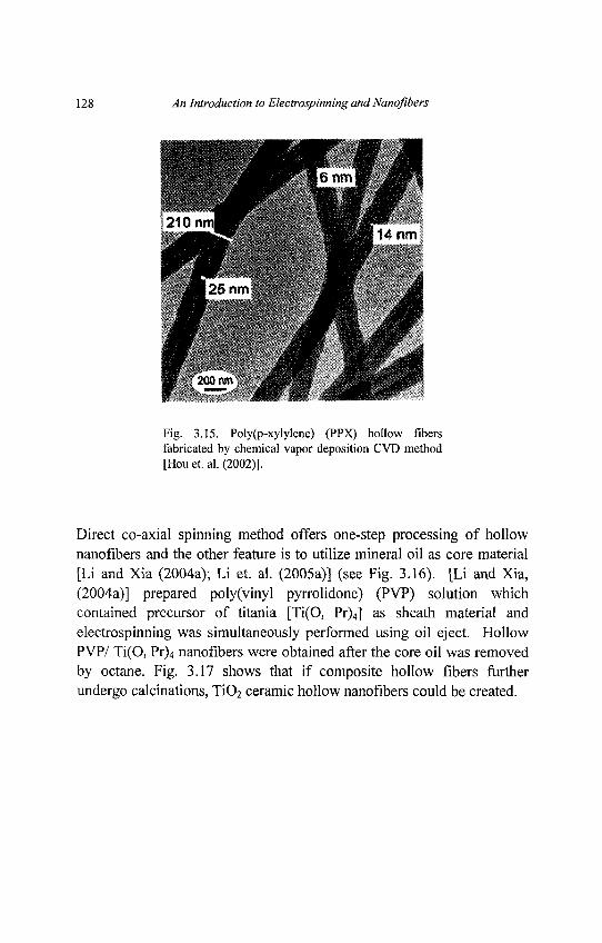
128 An Introduction to Electrospinning and Nanoflbers
Fig. 3.15. Poly(p-xylylene) (PPX) hollow fibersfabricated by chemical vapor deposition CVD method[Hou et. al. (2002)].
Direct co-axial spinning method offers one-step processing of hollownanoflbers and the other feature is to utilize mineral oil as core material[Li and Xia (2004a); Li et. al. (2005a)] (see Fig. 3.16). [Li and Xia,(2004a)] prepared poly(vinyl pyrrolidone) (PVP) solution whichcontained precursor of titania [Ti(O, Pr)4] as sheath material andelectrospinning was simultaneously performed using oil eject. HollowPVP/ Ti(O, Pr)4 nanoflbers were obtained after the core oil was removedby octane. Fig. 3.17 shows that if composite hollow fibers furtherundergo calcinations, TiO2 ceramic hollow nanoflbers could be created.
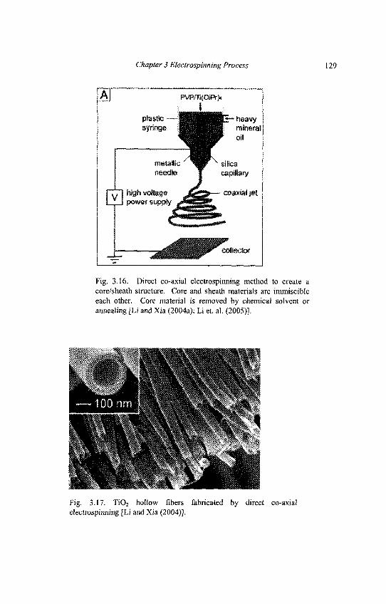
Chapter 3 Electrospinning Process 129
Fig. 3.16. Direct co-axial electrospinning method to create acore/sheath structure. Core and sheath materials are immiscibleeach other. Core material is removed by chemical solvent orannealing [Li and Xia (2004a); Li et. al. (2005)].
Fig. 3.17. TiO2 hollow fibers fabricated by direct co-axialelectrospinning [Li and Xia (2004)].
130 An Introduction to Electrospinning andNanoflbers
3.5.6. Fiber With Different Compositions
By using the co-axial electrospinning method shown in Fig. 3.16, it ispossible to achieve electrospun fibers with different polymers [Zhang et.al. (2004); Sun et. al. (2003)]. One advantage of using co-axialelectrospinning other then to produce hollow fibers is to produce corematerials that will not form fibers via electrospinning. The outer shellpolymeric material in this case, will serve as the template. Potentialapplications for this include drug delivery and photocatalysis.
Using a similar concept as co-axial electrospinning, another method ofproducing fiber with different compositions is to use side-by-sidebicomponent electrospinning method [Gupta and Wilkes (2003)]. In thisform of electrospinning, instead of having a capillary within a capillary,the two capillaries are placed side by side such that the resultant fiber iscomposed of two materials, side by side. The two polymer solutions donot come into physical contact until they reach the end of the spinneretwhere the electrospinning process is carried out. By using two differentpolymers, the fiber obtained will exhibit the properties of the twopolymers. However, the potential difference between the tip of the needleand the collector must be optimized to ensure the formation of acombined electrospinning jet. If the potential difference is too high, twoseparate electrospinning jets will form. The resultant electrospun fibersshowed that the amount of each given component can vary significantlyalong the fiber.
3.6. Uniformity and Productivity of Nanofiber Webs
Although electrospinning is a very simple process with huge potential forapplications in different areas, one of its main disadvantages is its lowproductivity. The usual feedrate for electrospinning is about 1.5ml/hr.Given a solution concentration of 0.2g/ml, the mass of nanofibercollected from a single needle after an hour is only 0.3g. In order forelectrospinning to be commercially viable, it is necessary to increase theproduction rate of the nanoflbers.
Chapter 3 Electrospinning Process 131
To do so, multiple-spinning setup is necessary to increase the yield whileat the same time maintaining the uniformity of the nanofiber mesh.
3.6.1. Jet Stability
To yield individual fibers, most, if not all of the solvents must beevaporated by the time the electrospinning jet reaches the collectionplate. As a result, volatile solvents are often used to dissolve thepolymer. However, clogging of the polymer may occur when the solventevaporates before the formation of Taylor cone during the extrusion ofthe solution from several needles. In order to maintain a stable jet whilestill using a volatile solvent, an effective method is to use a gas jacketaround the Taylor cone through two coaxial capillary tubes [Larsen et. al.(2004)]. The outer tube which surrounds the inner tube will provide acontrolled flow of inert gas which is saturated with the solvent used todissolve the polymer. The inner tube is then used to deliver the polymersolution. For 10 wt% poly(L-lactic acid) (PLLA) solution indichloromethane, electrospinning was not possible due to clogging of theneedle. However, when N2 gas was used to create a flowing gas jacket, astable Taylor cone was formed and electrospinning was carried outsmoothly.

132 An Introduction to Electrospinning andNanofibers
3.6.2. Multiple-spinning Setup
An obvious method of increasing the productivity of the nanofibers is touse multiple needles for electrospinning. As shown in Fig. 3.18, currentauthors make use of a multiple-spinning setup with a rotating mandrel.Polycaprolactone (PCL) solution with a feedrate of 24ml/hr wasdelivered to 8 needles using a single syringe pump. A nanofiber mesh of280(im thickness was fabricated within 45 minutes. In a separateexperiment [Ding et. al. (2004c)], a similar setup where four syringeswere clamped to a movable speed that moves from side to side at a speedof 20m/min was used to create a uniform fiber mesh. When multiplesyringes are used, the stability of the jet must be examined as the chargescarried by the individual jet will distort the electrostatic field andsubsequently influence other jets close to it [Theron et. al. (2005)]. Thedistance between the needles was kept at 3 cm as it was considered thatthere would be less interference between the adjacent jets at this distance.When multiple jets are employed, it is possible to spin different type ofpolymers simultaneously. The ratio of the polymer fibers is determinedby the ratio of the syringes containing the different polymers. Shouldthere be any clogging of the needles during electrospinning, gas jacketcan be used to improve the stability of the electrospinning process[Larsen et. al. (2004)]. Other similar mass production of electrospunfiber has been described in US Patent 6616435 B2 [Lee et. al. (2003b)]and US Patent 6713011 B2 [Chu et. al. (2004)].
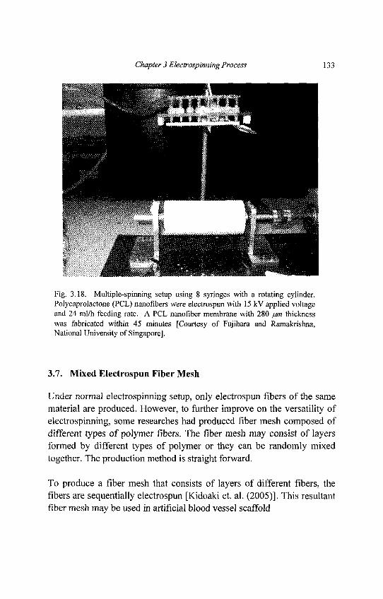
Chapter 3 Electrospinning Process 133
Fig. 3.18. Multiple-spinning setup using 8 syringes with a rotating cylinder.Polycaprolactone (PCL) nanofibers were electrospun with 15 kV applied voltageand 24 ml/h feeding rate. A PCL nanofiber membrane with 280 /jm thicknesswas fabricated within 45 minutes [Courtesy of Fujihara and Ramakrishna,National University of Singapore].
3.7. Mixed Electrospun Fiber Mesh
Under normal electrospinning setup, only electrospun fibers of the samematerial are produced. However, to further improve on the versatility ofelectrospinning, some researches had produced fiber mesh composed ofdifferent types of polymer fibers. The fiber mesh may consist of layersformed by different types of polymer or they can be randomly mixedtogether. The production method is straight forward.
To produce a fiber mesh that consists of layers of different fibers, thefibers are sequentially electrospun [Kidoaki et. al. (2005)]. This resultantfiber mesh may be used in artificial blood vessel scaffold
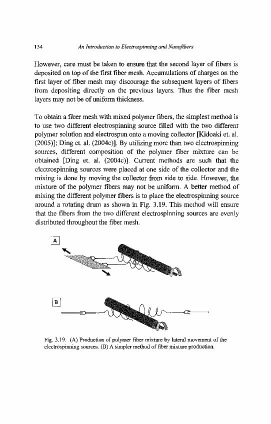
134 An Introduction to Electrospinning and Nanojibers
However, care must be taken to ensure that the second layer of fibers isdeposited on top of the first fiber mesh. Accumulations of charges on thefirst layer of fiber mesh may discourage the subsequent layers of fibersfrom depositing directly on the previous layers. Thus the fiber meshlayers may not be of uniform thickness.
To obtain a fiber mesh with mixed polymer fibers, the simplest method isto use two different electrospinning source filled with the two differentpolymer solution and electrospun onto a moving collector [Kidoaki et. al.(2005)]; Ding et. al. (2004c)]. By utilizing more than two electrospinningsources, different composition of the polymer fiber mixture can beobtained [Ding et. al. (2004c)]. Current methods are such that theelectrospinning sources were placed at one side of the collector and themixing is done by moving the collector from side to side. However, themixture of the polymer fibers may not be uniform. A better method ofmixing the different polymer fibers is to place the electrospinning sourcearound a rotating drum as shown in Fig. 3.19. This method will ensurethat the fibers from the two different electrospinning sources are evenlydistributed throughout the fiber mesh.
Fig. 3.19. (A) Production of polymer fiber mixture by lateral movement of theelectrospinning sources. (B) A simpler method of fiber mixture production.
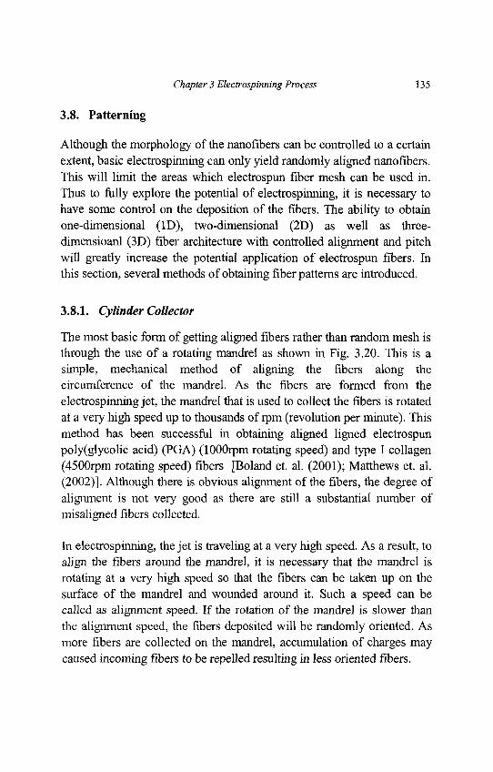
Chapter 3 Electrospinning Process 135
3.8. Patterning
Although the morphology of the nanofibers can be controlled to a certainextent, basic electrospinning can only yield randomly aligned nanofibers.This will limit the areas which electrospun fiber mesh can be used in.Thus to fully explore the potential of electrospinning, it is necessary tohave some control on the deposition of the fibers. The ability to obtainone-dimensional (ID), two-dimensional (2D) as well as three-dimensioanl (3D) fiber architecture with controlled alignment and pitchwill greatly increase the potential application of electrospun fibers. Inthis section, several methods of obtaining fiber patterns are introduced.
3.8.1. Cylinder Collector
The most basic form of getting aligned fibers rather than random mesh isthrough the use of a rotating mandrel as shown in Fig. 3.20. This is asimple, mechanical method of aligning the fibers along thecircumference of the mandrel. As the fibers are formed from theelectrospinning jet, the mandrel that is used to collect the fibers is rotatedat a very high speed up to thousands of rpm (revolution per minute). Thismethod has been successful in obtaining aligned ligned electrospunpoly(glycolic acid) (PGA) (lOOOrpm rotating speed) and type I collagen(4500rpm rotating speed) fibers [Boland et. al. (2001); Matthews et. al.(2002)]. Although there is obvious alignment of the fibers, the degree ofalignment is not very good as there are still a substantial number ofmisaligned fibers collected.
In electrospinning, the jet is traveling at a very high speed. As a result, toalign the fibers around the mandrel, it is necessary that the mandrel isrotating at a very high speed so that the fibers can be taken up on thesurface of the mandrel and wounded around it. Such a speed can becalled as alignment speed. If the rotation of the mandrel is slower thanthe alignment speed, the fibers deposited will be randomly oriented. Asmore fibers are collected on the mandrel, accumulation of charges maycaused incoming fibers to be repelled resulting in less oriented fibers.
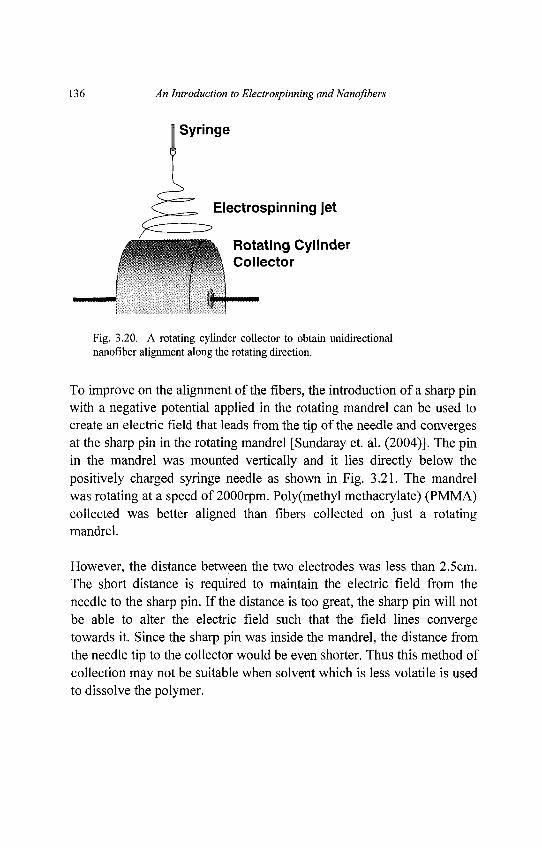
136 An Introduction to Electrospinning andNanofibers
Fig. 3.20. A rotating cylinder collector to obtain unidirectionalnanofiber alignment along the rotating direction.
To improve on the alignment of the fibers, the introduction of a sharp pinwith a negative potential applied in the rotating mandrel can be used tocreate an electric field that leads from the tip of the needle and convergesat the sharp pin in the rotating mandrel [Sundaray et. al. (2004)]. The pinin the mandrel was mounted vertically and it lies directly below thepositively charged syringe needle as shown in Fig. 3.21. The mandrelwas rotating at a speed of 2000rpm. Poly(methyl methacrylate) (PMMA)collected was better aligned than fibers collected on just a rotatingmandrel.
However, the distance between the two electrodes was less than 2.5cm.The short distance is required to maintain the electric field from theneedle to the sharp pin. If the distance is too great, the sharp pin will notbe able to alter the electric field such that the field lines convergetowards it. Since the sharp pin was inside the mandrel, the distance fromthe needle tip to the collector would be even shorter. Thus this method ofcollection may not be suitable when solvent which is less volatile is usedto dissolve the polymer.
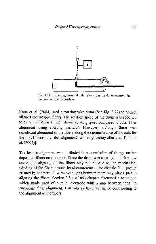
Chapter 3 Electrospinning Process 137
Fig. 3.21. Rotating mandrel with sharp pin inside to control thedirection of fiber deposition.
Katta et. al. (2004) used a rotating wire drum (See Fig. 3.22) to collectaligned electrospun fibers. The rotation speed of the drum was reportedto be lrpm. This is a much slower rotating speed compared to other fiberalignment using rotating mandrel. However, although there wassignificant alignment of the fibers along the circumference of the axis forthe first 15mins, the fiber alignment starts to go astray after that [Katta et.al. (2004)].
The loss in alignment was attributed to accumulation of charge on thedeposited fibers on the drum. Since the drum was rotating at such a lowspeed, the aligning of the fibers may not be due to the mechanicalwinding of the fibers around its circumference. The electric field profilecreated by the parallel wires with gaps between them may play a part inaligning the fibers. Section 3.8.4 of this chapter discussed a techniquewhich made used of parallel electrode with a gap between them toencourage fiber alignment. This may be the main factor contributing tothe alignment of the fibers.
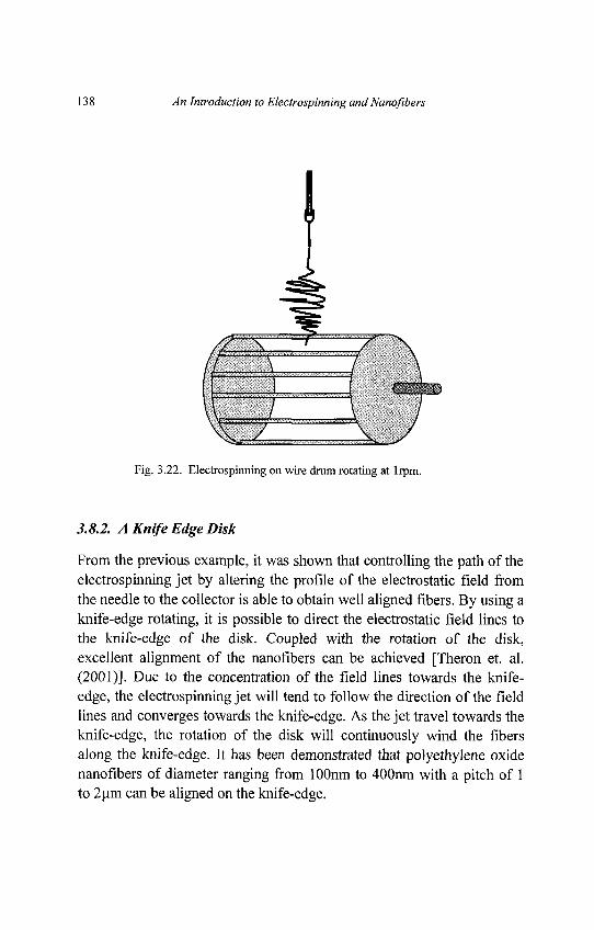
138 An Introduction to Electrospinning andNanofibers
Fig. 3.22. Electrospinning on wire drum rotating at lrpm.
3.8.2. A Knife Edge Disk
From the previous example, it was shown that controlling the path of theelectrospinning jet by altering the profile of the electrostatic field fromthe needle to the collector is able to obtain well aligned fibers. By using aknife-edge rotating, it is possible to direct the electrostatic field lines tothe knife-edge of the disk. Coupled with the rotation of the disk,excellent alignment of the nanofibers can be achieved [Theron et. al.(2001)]. Due to the concentration of the field lines towards the knife-edge, the electrospinning jet will tend to follow the direction of the fieldlines and converges towards the knife-edge. As the jet travel towards theknife-edge, the rotation of the disk will continuously wind the fibersalong the knife-edge. It has been demonstrated that polyethylene oxidenanofibers of diameter ranging from lOOnm to 400nm with a pitch of 1to 2um can be aligned on the knife-edge.
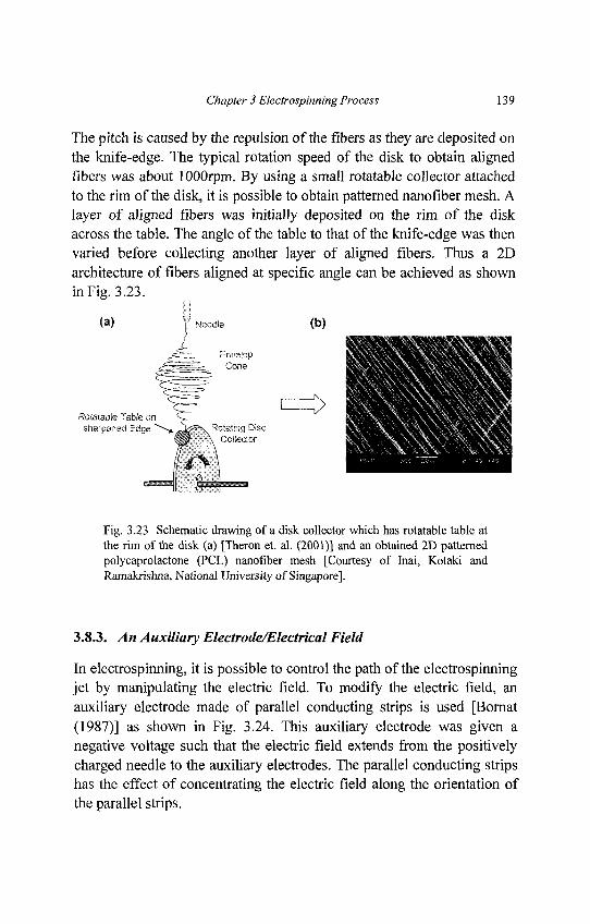
Chapter 3 Electrospinning Process 139
The pitch is caused by the repulsion of the fibers as they are deposited onthe knife-edge. The typical rotation speed of the disk to obtain alignedfibers was about 1 OOOrpm. By using a small rotatable collector attachedto the rim of the disk, it is possible to obtain patterned nanofiber mesh. Alayer of aligned fibers was initially deposited on the rim of the diskacross the table. The angle of the table to that of the knife-edge was thenvaried before collecting another layer of aligned fibers. Thus a 2Darchitecture of fibers aligned at specific angle can be achieved as shownin Fig. 3.23.
Fig. 3.23 Schematic drawing of a disk collector which has rotatable table atthe rim of the disk (a) [Theron et. al. (2001)] and an obtained 2D patternedpolycaprolactone (PCL) nanofiber mesh [Courtesy of Inai, Kotaki andRamakrishna, National University of Singapore].
3.8.3. An Auxiliary Electrode/Electrical Field
In electrospinning, it is possible to control the path of the electrospinningjet by manipulating the electric field. To modify the electric field, anauxiliary electrode made of parallel conducting strips is used [Bornat(1987)] as shown in Fig. 3.24. This auxiliary electrode was given anegative voltage such that the electric field extends from the positivelycharged needle to the auxiliary electrodes. The parallel conducting stripshas the effect of concentrating the electric field along the orientation ofthe parallel strips.
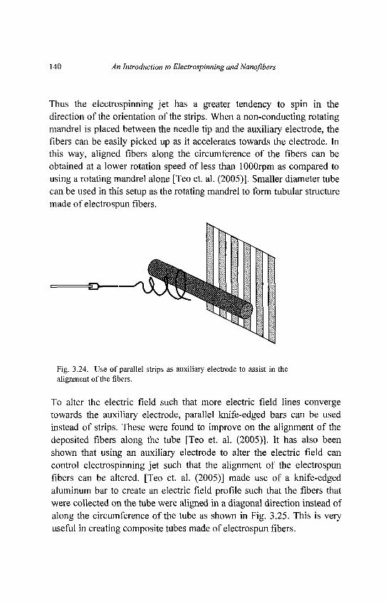
140 An Introduction to Electrospinning and Nanofibers
Thus the electrospinning jet has a greater tendency to spin in thedirection of the orientation of the strips. When a non-conducting rotatingmandrel is placed between the needle tip and the auxiliary electrode, thefibers can be easily picked up as it accelerates towards the electrode. Inthis way, aligned fibers along the circumference of the fibers can beobtained at a lower rotation speed of less than lOOOrpm as compared tousing a rotating mandrel alone [Teo et. al. (2005)]. Smaller diameter tubecan be used in this setup as the rotating mandrel to form tubular structuremade of electrospun fibers.
Fig. 3.24. Use of parallel strips as auxiliary electrode to assist in thealignment of the libers.
To alter the electric field such that more electric field lines convergetowards the auxiliary electrode, parallel knife-edged bars can be usedinstead of strips. These were found to improve on the alignment of thedeposited fibers along the tube [Teo et. al. (2005)]. It has also beenshown that using an auxiliary electrode to alter the electric field cancontrol electrospinning jet such that the alignment of the electrospunfibers can be altered. [Teo et. al. (2005)] made use of a knife-edgedaluminum bar to create an electric field profile such that the fibers thatwere collected on the tube were aligned in a diagonal direction instead ofalong the circumference of the tube as shown in Fig. 3.25. This is veryuseful in creating composite tubes made of electrospun fibers.
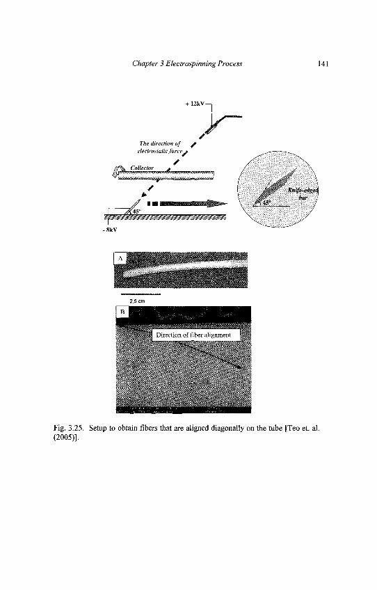
Chapter 3 Electrospinning Process 141
Fig. 3.25. Setup to obtain fibers that are aligned diagonally on the tube [Teo et. al.(2005)].
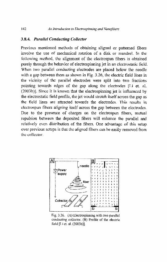
142 An Introduction to Electrospinning and Nanoflbers
3.8.4. Parallel Conducting Collector
Previous mentioned methods of obtaining aligned or patterned fibersinvolve the use of mechanical rotation of a disk or mandrel. In thefollowing method, the alignment of the electrospun fibers is obtainedpurely through the behavior of electrospinning jet in an electrostatic field.When two parallel conducting electrodes are placed below the needlewith a gap between them as shown in Fig. 3.26, the electric field lines inthe vicinity of the parallel electrodes were split into two fractionspointing towards edges of the gap along the electrodes [Li et. al.(2003b)]. Since it is known that the electrospinning jet is influenced bythe electrostatic field profile, the jet would stretch itself across the gap asthe field lines are attracted towards the electrodes. This results inelectrospun fibers aligning itself across the gap between the electrodes.Due to the presence of charges on the electrospun fibers, mutualrepulsion between the deposited fibers will enhance the parallel andrelatively even distribution of the fibers. One advantage of this setupover previous setups is that the aligned fibers can be easily removed fromthe collector.
Fig. 3.26. (A) Electrospinning with two parallelconducting collector. (B) Profile of the electricfield [Li et. al. (2003b)].
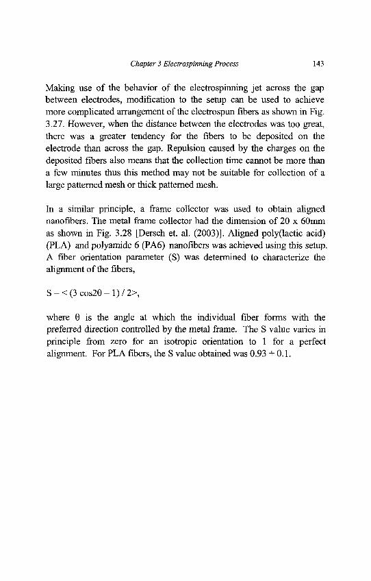
Chapter 3 Electrospinning Process 143
Making use of the behavior of the electrospinning jet across the gapbetween electrodes, modification to the setup can be used to achievemore complicated arrangement of the electrospun fibers as shown in Fig.3.27. However, when the distance between the electrodes was too great,there was a greater tendency for the fibers to be deposited on theelectrode than across the gap. Repulsion caused by the charges on thedeposited fibers also means that the collection time cannot be more thana few minutes thus this method may not be suitable for collection of alarge patterned mesh or thick patterned mesh.
In a similar principle, a frame collector was used to obtain alignednanofibers. The metal frame collector had the dimension of 20 x 60mmas shown in Fig. 3.28 [Dersch et. al. (2003)]. Aligned poly(lactic acid)(PLA) and polyamide 6 (PA6) nanofibers was achieved using this setup.A fiber orientation parameter (S) was determined to characterize thealignment of the fibers,
S = < (3 cos20 - 1) / 2>,
where 9 is the angle at which the individual fiber forms with thepreferred direction controlled by the metal frame. The S value varies inprinciple from zero for an isotropic orientation to 1 for a perfectalignment. For PLA fibers, the S value obtained was 0.93 + 0.1.
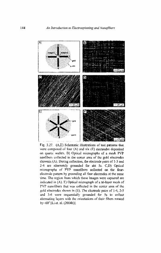
144 An Introduction to Electrospinning and Nanofibers
Fig. 3.27. (A,E) Schematic illustrations of test patterns thatwere composed of four (A) and six (E) electrodes depositedon quartz wafers. B) Optical micrographs of a mesh PVPnaofibers collected in the center area of the gold electrodesshownin (A). During collection, the electrode pairs of 1-3 and2-4 are alternately grounded for abt 5s. C,D) Opticalmicrographs of PVP nanofibers collected on the four-electrode pattern by grounding all four electrodes at the sametime. The region from which these images were captured areindicated in (A). F) Optical micrograph of a tri-layer mesh ofPVP nanofibers that was collected in the center area of thegold electrodes shown in (E). The electrode pairs of 1-4, 2-5and 3-6 were sequentially grounded for 5s to collectalternating layers with the orientations of their fibers rotatedby~60°[Liet.al. (2004b)].
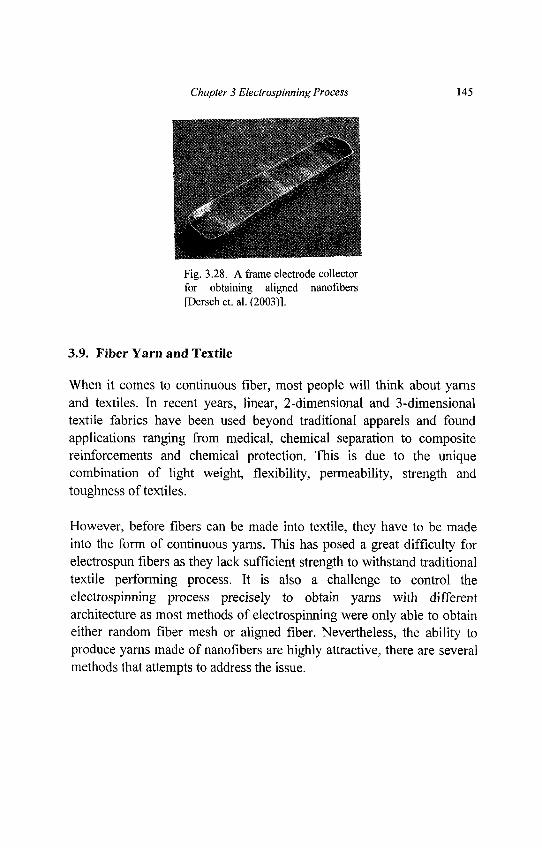
Chapter 3 Electrospinning Process 145
Fig. 3.28. A frame electrode collectorfor obtaining aligned nanofibers[Dersch et. al. (2003)1.
3.9. Fiber Yarn and Textile
When it comes to continuous fiber, most people will think about yarnsand textiles. In recent years, linear, 2-dimensional and 3-dimensionaltextile fabrics have been used beyond traditional apparels and foundapplications ranging from medical, chemical separation to compositereinforcements and chemical protection. This is due to the uniquecombination of light weight, flexibility, permeability, strength andtoughness of textiles.
However, before fibers can be made into textile, they have to be madeinto the form of continuous yarns. This has posed a great difficulty forelectrospun fibers as they lack sufficient strength to withstand traditionaltextile performing process. It is also a challenge to control theelectrospinning process precisely to obtain yarns with differentarchitecture as most methods of electrospinning were only able to obtaineither random fiber mesh or aligned fiber. Nevertheless, the ability toproduce yarns made of nanofibers are highly attractive, there are severalmethods that attempts to address the issue.
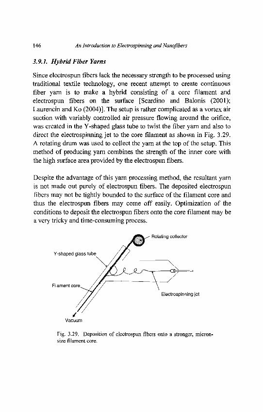
146 An Introduction to Electrospinning and Nanofibers
3.9.1. Hybrid Fiber Yarns
Since electrospun fibers lack the necessary strength to be processed usingtraditional textile technology, one recent attempt to create continuousfiber yarn is to make a hybrid consisting of a core filament andelectrospun fibers on the surface [Scardino and Balonis (2001);Laurencin and Ko (2004)]. The setup is rather complicated as a vortex airsuction with variably controlled air pressure flowing around the orifice,was created in the Y-shaped glass tube to twist the fiber yarn and also todirect the electrospinning jet to the core filament as shown in Fig. 3.29.A rotating drum was used to collect the yarn at the top of the setup. Thismethod of producing yarn combines the strength of the inner core withthe high surface area provided by the electrospun fibers.
Despite the advantage of this yarn processing method, the resultant yarnis not made out purely of electrospun fibers. The deposited electrospunfibers may not be tightly bounded to the surface of the filament core andthus the electrospun fibers may come off easily. Optimization of theconditions to deposit the electrospun fibers onto the core filament may bea very tricky and time-consuming process.
Fig. 3.29. Deposition of electrospun fibers onto a stronger, micron-size filament core.
Chapter 3 Electrospinning Process 147
3.9.2. Electrospun Fiber Yarn
There are a few methods where electrospinning is able to yieldelectrospun fiber yarn. However, the resultant fiber yarns are of limitedlength. In section 3.8.2 of this chapter, where a rotating disk was used tocollect highly aligned electrospun fibers, a bundle of highly alignedfibers can be taken off the edges of the disk. However, in this case, thelength of the yarn is limited by the circumference of the knife-edged disk.In a similar attempt to obtain a continuous yarn made of aligned fibers,fiber bundles are obtained by collecting the electrospun fibers on arotating drum. The collected nanofibers were linked and twisted intoyarns [Fennessey and Farris (2004)]. However, there were nodescriptions of how the nanofibers were linked and twisted. Since thenanofibers were linked rather than being long continuous strands, theresultant yarns may be weak at the links.
[Khil et. al. (2005)] used a novel method to producing long, continuousfiber yarn. The method relies on deposition of the electrospun fibers ontoa water bath as shown in Fig. 3.30. The deposited fibers were than drawnout of the water as a bundle from the side of the water bath usingfilament guide bar and collected onto a roller in the form of a yarn. Theuse of non-solvent such as water also has the advantage of coagulatingthe fibers especially when less volatile solvents are used to dissolve thepolymer [Reneker and Chun (1996)].
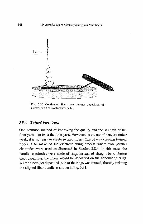
148 An Introduction to Electrospinning and Nanofibers
Fig. 3.30 Continuous fiber yarn through deposition ofelectrospun fibers onto water bath.
3.9.3. Twisted Fiber Yarn
One common method of improving the quality and the strength of thefiber yarn is to twist the fiber yarn. However, as the nanofibers are ratherweak, it is not easy to create twisted fibers. One of way creating twistedfibers is to make of the electrospinning process where two parallelelectrodes were used as discussed in Section 3.8.4. In this case, theparallel electrodes were made of rings instead of straight bars. Duringelectrospinning, the fibers would be deposited on the conducting rings.As the fibers get deposited, one of the rings was rotated, thereby twistingthe aligned fiber bundle as shown in Fig. 3.31.
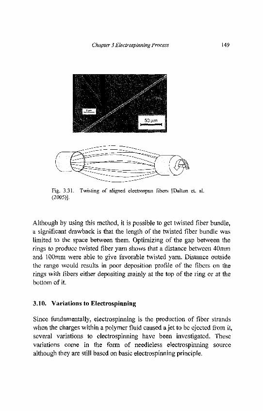
Chapter 3 Electrospinning Process 149
Fig. 3.31. Twisting of aligned electrospun fibers [Dalton et. al.(2005)].
Although by using this method, it is possible to get twisted fiber bundle,a significant drawback is that the length of the twisted fiber bundle waslimited to the space between them. Optimizing of the gap between therings to produce twisted fiber yarn shows that a distance between 40mmand 100mm were able to give favorable twisted yarn. Distance outsidethe range would results in poor deposition profile of the fibers on therings with fibers either depositing mainly at the top of the ring or at thebottom of it.
3.10. Variations to Electrospinning
Since fundamentally, electrospinning is the production of fiber strandswhen the charges within a polymer fluid caused a jet to be ejected from it,several variations to electrospinning have been investigated. Thesevariations come in the form of needleless electrospinning sourcealthough they are still based on basic electrospinning principle.
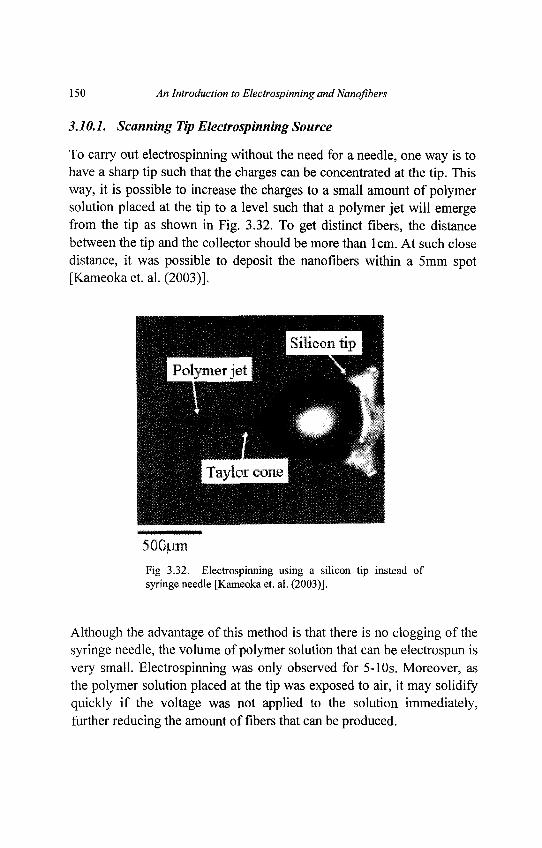
150 An Introduction to Electrospinning and Nanoflbers
3.10.1. Scanning Tip Electrospinning Source
To carry out electrospinning without the need for a needle, one way is tohave a sharp tip such that the charges can be concentrated at the tip. Thisway, it is possible to increase the charges to a small amount of polymersolution placed at the tip to a level such that a polymer jet will emergefrom the tip as shown in Fig. 3.32. To get distinct fibers, the distancebetween the tip and the collector should be more than lcm. At such closedistance, it was possible to deposit the nanoflbers within a 5mm spot[Kameoka et. al. (2003)].
Fig 3.32. Electrospinning using a silicon tip instead ofsyringe needle [Kameoka et. al. (2003)].
Although the advantage of this method is that there is no clogging of thesyringe needle, the volume of polymer solution that can be electrospun isvery small. Electrospinning was only observed for 5-10s. Moreover, asthe polymer solution placed at the tip was exposed to air, it may solidifyquickly if the voltage was not applied to the solution immediately,further reducing the amount of fibers that can be produced.
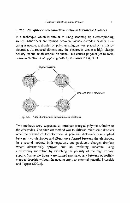
Chapter 3 Electrospinning Process 151
3.10.2. Nanofiber Interconnections Between Microscale Features
In a technique which is similar to using scanning tip electrospinningsource, nanofibers are formed between micro-electrodes. Rather thenusing a needle, a droplet of polymer solution was placed on a micro-electrode. At reduced dimensions, the electrodes create a high chargedensity on the small droplet on them. This causes polymer jet to formbetween electrodes of opposing polarity as shown in Fig. 3.33.
Fig. 3.33. Nanofibers formed between mkru-electodes.
Two methods were suggested to introduce charged polymer solution tothe electrodes. The simplest method was to airbrush microscale dropletsonto the surface of the electrode. A potential difference was appliedbetween two electrodes and fibers were formed between the electrodes.In a second method, both negatively and positively charged dropletswhere alternatively sprayed onto an insulating substrate usingelectrospray ionization by switching the polarity of the high voltagesupply. Nanoscale fibers were formed spontaneously between oppositelycharged droplets without the need to apply an external potential [Kessickand Tepper (2003)].
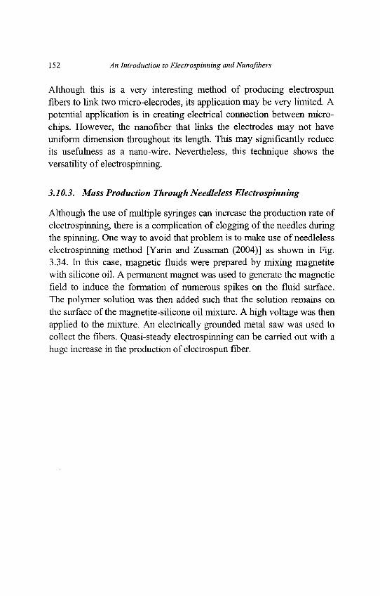
152 An Introduction to Electrospinning and Nanoflbers
Although this is a very interesting method of producing electrospunfibers to link two micro-elecrodes, its application may be very limited. Apotential application is in creating electrical connection between micro-chips. However, the nanofiber that links the electrodes may not haveuniform dimension throughout its length. This may significantly reduceits usefulness as a nano-wire. Nevertheless, this technique shows theversatility of electrospinning.
3.10.3. Mass Production Through Needleless Electrospinning
Although the use of multiple syringes can increase the production rate ofelectrospinning, there is a complication of clogging of the needles duringthe spinning. One way to avoid that problem is to make use of needlelesselectrospinning method [Yarin and Zussman (2004)] as shown in Fig.3.34. In this case, magnetic fluids were prepared by mixing magnetitewith silicone oil. A permanent magnet was used to generate the magneticfield to induce the formation of numerous spikes on the fluid surface.The polymer solution was then added such that the solution remains onthe surface of the magnetite-silicone oil mixture. A high voltage was thenapplied to the mixture. An electrically grounded metal saw was used tocollect the fibers. Quasi-steady electrospinning can be carried out with ahuge increase in the production of electrospun fiber.
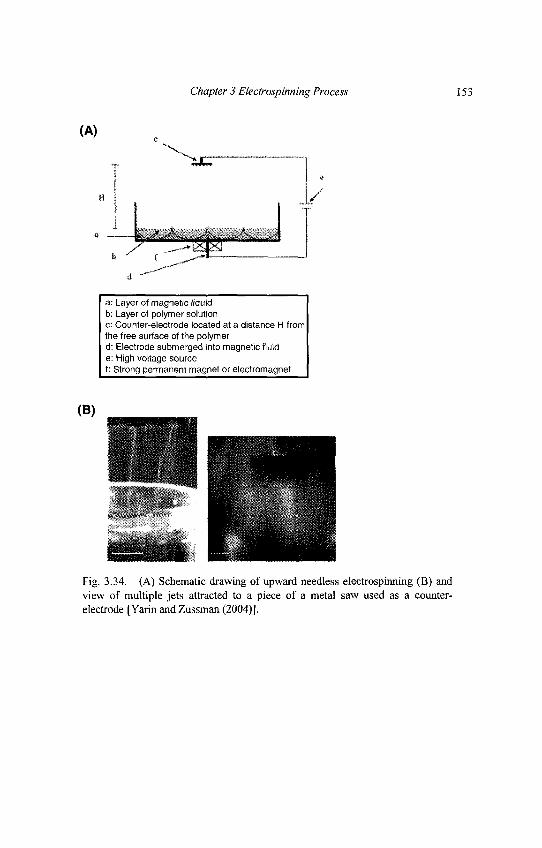
Chapter 3 Electrospinning Process 153
Fig. 3.34. (A) Schematic drawing of upward needless electrospinning (B) andview of multiple jets attracted to a piece of a metal saw used as a counter-electrode [Yarin and Zussman (2004)].
154 An Introduction to Electrospinning and Nanofibers
3.11. Conclusions
In order to control any process, it is important to investigate theparameters that influence it. By varying the parameters, electrospunfibers of different diameters, fiber surface porosity, beaded and non-beaded fibers can be produced. Depending on the application, fibers withdifferent morphology and structures can be produced by using specificparameters and setups. The type of fiber mesh produced can also bevaried by using different setups. Tubular scaffold and yarns, made ofboth aligned and random fibers can be produced till date. Structuresmade of fibers arranged in specific patterns may also be producedthrough electrospinning. All these are possible by manipulation of theexternal electric field and using different types of collector. With greaterunderstanding of electrospinning, we may be able to have a greatercontrol over the behavior of the electrospinning jet and its resultant fibers.
Chapter 4
Modeling of the Electrospinning Process
4.0. Nomenclature
Unless otherwise specified, the symbols used in this chapter adhere to thefollowing nomenclature.
a = coefficient of surface tension8 = radial perturbationE = vertical component of electric field or Young's moduluse = charge
£ = strain
/ = forceG = elastic modulusg = gravitational accelerationy = shearh = distance from pendent drop to ground collector/ = constant total current in the jet or second moment of areaK = liquid conductivityk = jet curvature
e \TL = — J = length scale
R0^nGI = length of ideal rectilinear jetX = perturbation wave lengthM = linear momentum
155

156 An Introduction to Electrospinning andNanofibers
m = equivalent massju =viscosityn = flow index of non-Newtonian fluidv = kinematic viscosityP = position coordinatep = liquid pressureR = jet radiusR' =slope of jet surface with respect to jet axis.
Ro = initial jet radius
r = radial distance from jet axisp = densitya =surface charge density or normal stressov = viscoelastic stressT = surface tensiont = timeT = shear stress
Vo = applied voltage
v = jet velocityco = perturbation frequencyz = downward vertical distance from pendant droplet
Chapter 4 Modeling of the Electrospinning Process 157
4.1. Introduction
The importance of electrospinning process modeling is significant.Although knowledge on the effect of various processing parameters andconstituent material properties can be obtained experimentally,theoretical models offer in-depth scientific understanding which can beuseful to shed light on the contributing factors that cannot be fullymeasured experimentally. Results from modeling also elucidate howprocessing parameters and fluid behavior lead to the nanofiber of desiredproperties. The term "properties" refers to basic properties (such as fiberdiameter, surface roughness, fiber connectivity, etc), physical properties(such as stiffness, toughness, thermal conductivity, electrical resistivity,thermal expansion coefficient, opaqueness, density, etc) and specializedproperties (such as biocompatibility, degradation curve, etc forbiomedical applications). In addition to electrospinning of polymersolution for obtaining nanofibers, other variations of electrospinningexists, namely the combined electrospinning and sol-gel process [Choi etal. (2003a & 2004d)] and the melt-electrospinning processes [Khurana etal. (2003); Lyons et al. (2003 & 2004)]. Since this chapter deals with theelectrospun nanofibers, we herein consider the modeling aspects ofsimple electrospinning that uses polymer solution.
Needles to say, the various methods formulated by numerous researchgroups are highly motivated by different intended applications of thenanofibers, as well as their academic familiarity. It would be sufficient,in this chapter, to briefly describe the different methods adopted, observethe similarities and discrepancies in all their approaches. Then, wereview some results that can be useful to bear in mind for those whointend to begin the research and development of nanofibers using theelectrospinning process.
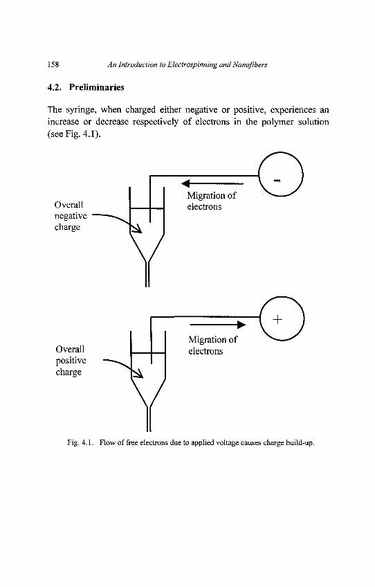
158 An Introduction to Electrospinning and Nanofibers
4.2. Preliminaries
The syringe, when charged either negative or positive, experiences anincrease or decrease respectively of electrons in the polymer solution(see Fig. 4.1).
Fig. 4.1. Flow of free electrons due to applied voltage causes charge build-up.
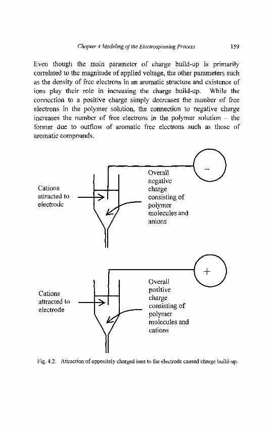
Chapter 4 Modeling of the Electrospinning Process 159
Even though the main parameter of charge build-up is primarilycorrelated to the magnitude of applied voltage, the other parameters suchas the density of free electrons in an aromatic structure and existence ofions play their role in increasing the charge build-up. While theconnection to a positive charge simply decreases the number of freeelectrons in the polymer solution, the connection to negative chargeincreases the number of free electrons in the polymer solution - theformer due to outflow of aromatic free electrons such as those ofaromatic compounds.
Fig. 4.2. Attraction of oppositely charged ions to the electrode caused charge build-up.
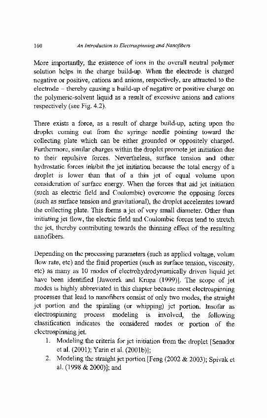
160 An Introduction to Electrospinning and Nanoflbers
More importantly, the existence of ions in the overall neutral polymersolution helps in the charge build-up. When the electrode is chargednegative or positive, cations and anions, respectively, are attracted to theelectrode - thereby causing a build-up of negative or positive charge onthe polymeric-solvent liquid as a result of excessive anions and cationsrespectively (see Fig. 4.2).
There exists a force, as a result of charge build-up, acting upon thedroplet coming out from the syringe needle pointing toward thecollecting plate which can be either grounded or oppositely charged.Furthermore, similar charges within the droplet promote jet initiation dueto their repulsive forces. Nevertheless, surface tension and otherhydrostatic forces inhibit the jet initiation because the total energy of adroplet is lower than that of a thin jet of equal volume uponconsideration of surface energy. When the forces that aid jet initiation(such as electric field and Coulombic) overcome the opposing forces(such as surface tension and gravitational), the droplet accelerates towardthe collecting plate. This forms a jet of very small diameter. Other thaninitiating jet flow, the electric field and Coulombic forces tend to stretchthe jet, thereby contributing towards the thinning effect of the resultingnanofibers.
Depending on the processing parameters (such as applied voltage, volumflow rate, etc) and the fluid properties (such as surface tension, viscosity,etc) as many as 10 modes of electrohydrodynamically driven liquid jethave been identified [Jaworek and Krupa (1999)]. The scope of jetmodes is highly abbreviated in this chapter because most electrospinningprocesses that lead to nanofibers consist of only two modes, the straightjet portion and the spiraling (or whipping) jet portion. Insofar aselectrospinning process modeling is involved, the followingclassification indicates the considered modes or portion of theelectrospinning jet.
1. Modeling the criteria for jet initiation from the droplet [Senadoret al. (2001); Yarin et al. (2001b)];
2. Modeling the straight jet portion [Feng (2002 & 2003); Spivak etal. (1998 & 2000)]; and
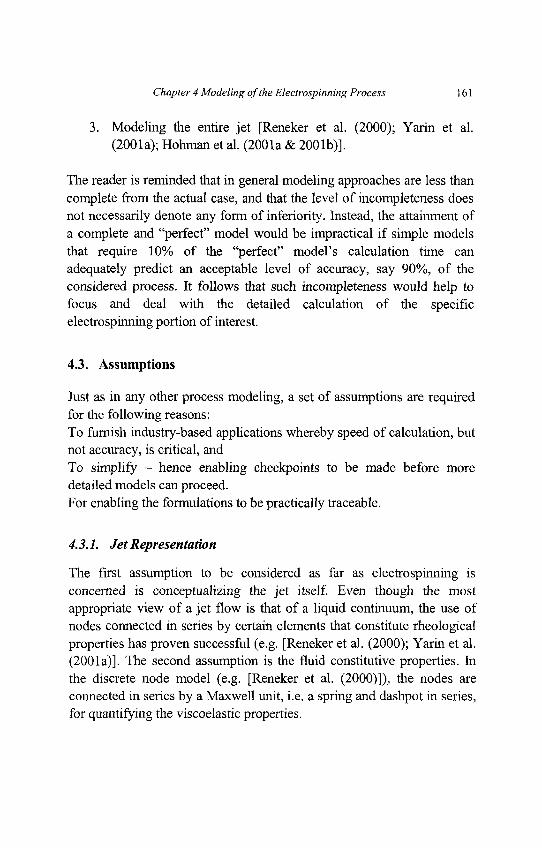
Chapter 4 Modeling of the Electrospinning Process 161
3. Modeling the entire jet [Reneker et al. (2000); Yarin et al.(2001a); Hohman et al. (2001a & 2001b)].
The reader is reminded that in general modeling approaches are less thancomplete from the actual case, and that the level of incompleteness doesnot necessarily denote any form of inferiority. Instead, the attainment ofa complete and "perfect" model would be impractical if simple modelsthat require 10% of the "perfect" model's calculation time canadequately predict an acceptable level of accuracy, say 90%, of theconsidered process. It follows that such incompleteness would help tofocus and deal with the detailed calculation of the specificelectrospinning portion of interest.
4.3. Assumptions
Just as in any other process modeling, a set of assumptions are requiredfor the following reasons:To furnish industry-based applications whereby speed of calculation, butnot accuracy, is critical, andTo simplify - hence enabling checkpoints to be made before moredetailed models can proceed.For enabling the formulations to be practically traceable.
4.3.1. Jet Representation
The first assumption to be considered as far as electrospinning isconcerned is conceptualizing the jet itself. Even though the mostappropriate view of a jet flow is that of a liquid continuum, the use ofnodes connected in series by certain elements that constitute rheologicalproperties has proven successful (e.g. [Reneker et al. (2000); Yarin et al.(2001a)]. The second assumption is the fluid constitutive properties. Inthe discrete node model (e.g. [Reneker et al. (2000)]), the nodes areconnected in series by a Maxwell unit, i.e. a spring and dashpot in series,for quantifying the viscoelastic properties.
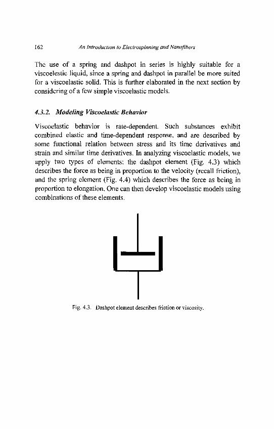
162 An Introduction to Electrospinning and Nanofibers
The use of a spring and dashpot in series is highly suitable for aviscoelestic liquid, since a spring and dashpot in parallel be more suitedfor a viscoelastic solid. This is further elaborated in the next section byconsidering of a few simple viscoelastic models.
4.3.2. Modeling Viscoelastic Behavior
Viscoelastic behavior is rate-dependent. Such substances exhibitcombined elastic and time-dependent response, and are described bysome functional relation between stress and its time derivatives andstrain and similar time derivatives. In analyzing viscoelastic models, weapply two types of elements: the dashpot element (Fig. 4.3) whichdescribes the force as being in proportion to the velocity (recall friction),and the spring element (Fig. 4.4) which describes the force as being inproportion to elongation. One can then develop viscoelastic models usingcombinations of these elements.
Fig. 4.3. Dashpot element describes friction or viscosity.
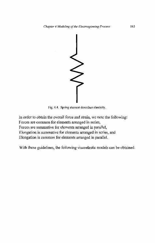
Chapter 4 Modeling of the Electrospinning Process 163
Fig. 4.4. Spring element describes elasticity.
In order to obtain the overall force and strain, we note the following:Forces are common for elements arranged in series,Forces are summative for elements arranged in parallel,Elongation is summative for elements arranged in series, andElongation is common for elements arranged in parallel.
With these guidelines, the following viscoelastic models can be obtained:
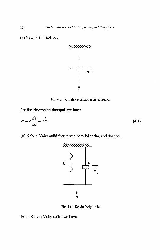
164 An Introduction to Electrospinning and Nanqflbers
(a) Newtonian dashpot.
Fig. 4.5. A highly idealized inviscid liquid.
For the Newtonian dashpot, we have
ds<j = c — - c s . (4.1)
dt
(b) Kelvin-Voigt solid featuring a parallel spring and dashpot.
Y///////////A
E ^> I c
o
Fig. 4.6. Kelvin-Voigt solid.
For a Kelvin-Voigt solid, we have
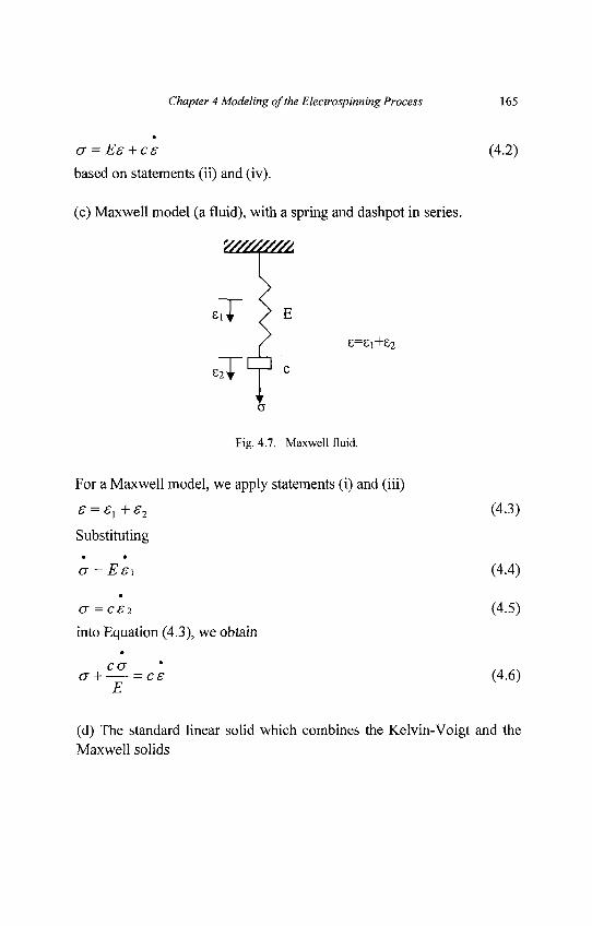
Chapter 4 Modeling of the Electro spinning Process 165
a = Es + cs (4.2)
based on statements (ii) and (iv).
(c) Maxwell model (a fluid), with a spring and dashpot in series.
Fig. 4.7. Maxwell fluid.
For a Maxwell model, we apply statements (i) and (iii)
s = s, + s2 (4.3)
Substituting
er = Eei (4.4)
a -c£2 (4.5)
into Equation (4.3), we obtain
(7 H = C£ (4.6)E
(d) The standard linear solid which combines the Kelvin-Voigt and theMaxwell solids
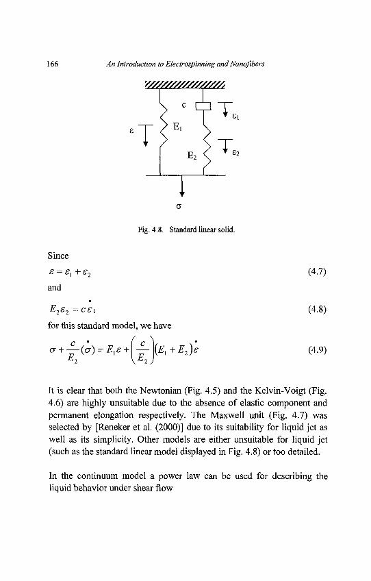
166 An Introduction to Electrospinning and Nanofibers
Fig. 4.8. Standard linear solid.
Since
s = sx + s2 (4.7)
and
E2s2 -cs\ (4.8)
for this standard model, we have
^ + -^r^) = El£ + \^r\{El+E2)£ (4.9)t2 \KL2J
It is clear that both the Newtonian (Fig. 4.5) and the Kelvin-Voigt (Fig.4.6) are highly unsuitable due to the absence of elastic component andpermanent elongation respectively. The Maxwell unit (Fig. 4.7) wasselected by [Reneker et al. (2000)] due to its suitability for liquid jet aswell as its simplicity. Other models are either unsuitable for liquid jet(such as the standard linear model displayed in Fig. 4.8) or too detailed.
In the continuum model a power law can be used for describing theliquid behavior under shear flow
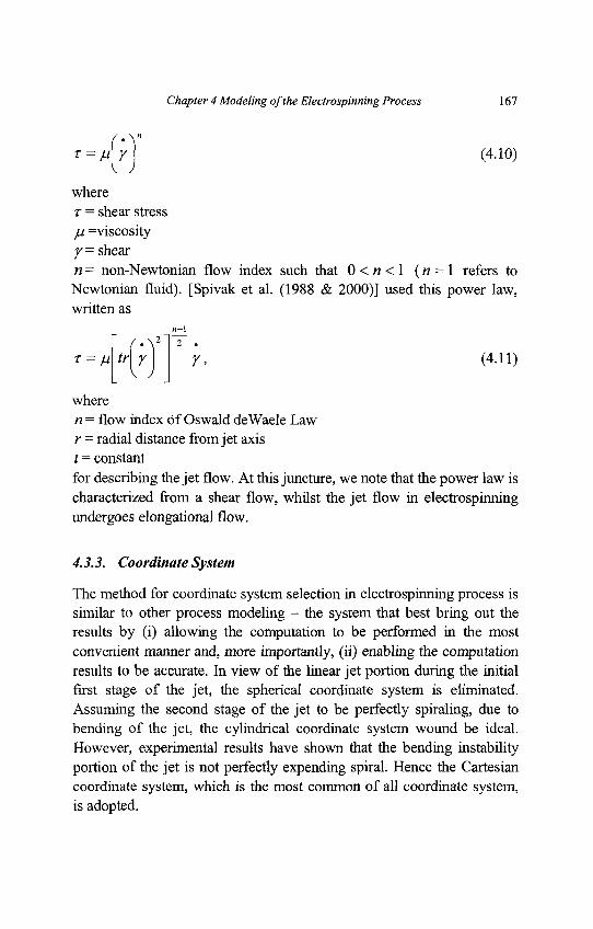
Chapter 4 Modeling of the Electrospinning Process 167
T = dr) (4.io)
wherer = shear stressju =viscosityy= shear« = non-Newtonian flow index such that 0 < « < l (« = 1 refers toNewtonian fluid). [Spivak et al. (1988 & 2000)] used this power law,written as
n-l
T = Mtr]r) r, (4-ii)
wheren = flow index of Oswald deWaele Lawr = radial distance from jet axist = constantfor describing the jet flow. At this juncture, we note that the power law ischaracterized from a shear flow, whilst the jet flow in electrospinningundergoes elongational flow.
4.3.3. Coordinate System
The method for coordinate system selection in electrospinning process issimilar to other process modeling - the system that best bring out theresults by (i) allowing the computation to be performed in the mostconvenient manner and, more importantly, (ii) enabling the computationresults to be accurate. In view of the linear jet portion during the initialfirst stage of the jet, the spherical coordinate system is eliminated.Assuming the second stage of the jet to be perfectly spiraling, due tobending of the jet, the cylindrical coordinate system wound be ideal.However, experimental results have shown that the bending instabilityportion of the jet is not perfectly expending spiral. Hence the Cartesiancoordinate system, which is the most common of all coordinate system,is adopted.
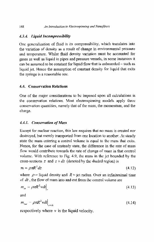
168 An Introduction to Electrospinning and Nanofibers
4.3.4. Liquid Incompressibility
One generalization of fluid is its compressibility, which translates intothe variation of density as a result of change in environmental pressureand temperature. Whilst fluid density variation must be accounted forgases as well as liquid in pipes and pressure vessels, in some instances itcan be assumed to be constant for liquid flow that is unbounded - such asliquid jet. Hence the assumption of constant density for liquid that exitsthe syringe is a reasonable one.
4.4. Conservation Relations
One of the major considerations to be imposed upon all calculations isthe conservation relations. Most electrospinning models apply threeconservation quantities, namely that of the mass, the momentum, and thecharge.
4.4.1. Conservation of Mass
Except for nuclear reaction, this law requires that no mass is created nordestroyed, but merely transported from one location to another. At steadystate the mass entering a control volume is equal to the mass that exits.Hence, for the case of unsteady state, the difference in the rate of massflow would contribute towards the rate of change of mass in that controlvolume. With reference to Fig. 4.9, the mass in the jet bounded by thecross-sections z and z + dz (denoted by the shaded region) is
m = pnR2dz (4.12)
where p = liquid density and R = jet radius. Over an infinitesimal timeof dt, the flow of mass into and out from the control volume are
mln = pnR2vdt\ (4.13)
and
moul = pnR2vdt (4.14)z+az
respectively where v is the liquid velocity.
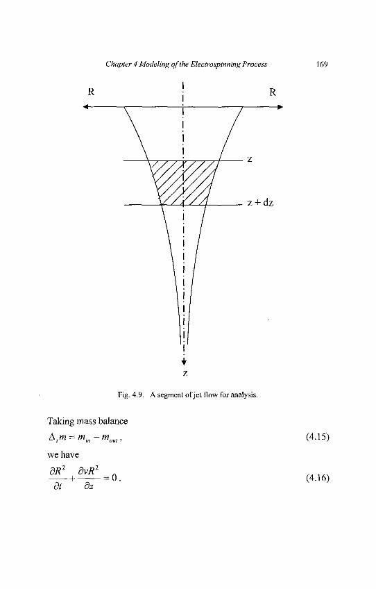
Chapter 4 Modeling of the Electrospinning Process 169
Fig. 4.9. A segment of jet flow for analysis.
Taking mass balance
Atm = min-moul, (4.15)
we have
1 = 0. (4.16)dt dz
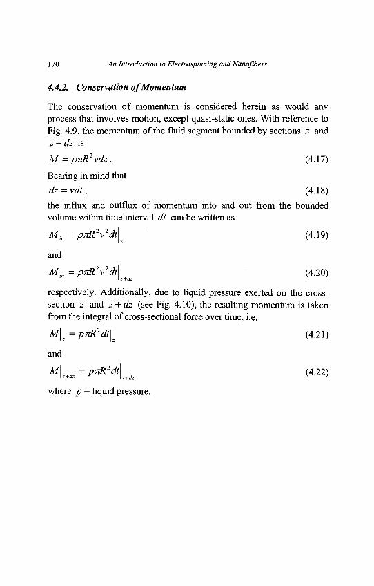
170 An Introduction to Electrospinning and Nanofibers
4.4.2. Conservation of Momentum
The conservation of momentum is considered herein as would anyprocess that involves motion, except quasi-static ones. With reference toFig. 4.9, the momentum of the fluid segment bounded by sections z andz + dz is
M = pnR2vdz. (4.17)
Bearing in mind that
dz = vdt, (4.18)
the influx and outflux of momentum into and out from the boundedvolume within time interval dt can be written as
Min = pnR2v2dt\^ (4.19)
and
Min=pnR2v2dt (4.20)z+dz
respectively. Additionally, due to liquid pressure exerted on the cross-section z and z + dz (see Fig. 4.10), the resulting momentum is takenfrom the integral of cross-sectional force over time, i.e.
M\z = p7rR2dt (4.21)
and
M\ =pnR2dt (4.22)i z+dz z+dz V '
where p = liquid pressure.
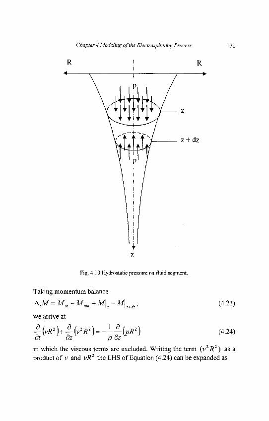
Chapter 4 Modeling of the Electrospinning Process 171
Fig. 4.10 Hydrostatic pressure on fluid segment.
Taking momentum balance
A,M = Mm -M0M +M\z -M\z+dz, (4.23)
we arrive at
in which the viscous terms are excluded. Writing the term (v2i?2) as aproduct of v and vi?2 the LHS of Equation (4.24) can be expanded as
172 An Introduction to Electrospinning and Nanofibers
2 dv dR2 dvR1 n2 dv 1 dpR2 .. . . .
R2 — + v + v + vR — = — . (4.25)dt dt dz dz p dz
The purpose of splitting the second term on the LHS of Equation (4.24)as above is intended to allow the second and third terms on the LHS ofEquation (4.25) to be cancelled by virtue of Equation (4.16). Hencedv dv 1 dpR2
— + v— = -— (4.26)dt dz pR2 dz
A more detailed momentum balance equation was developed by [Feng(2002)] as follows:
^(7rR2pv)=xR2pg + ̂ [7iR2{-p + Tzz)]+?-2nRR<+27rR(t:-t:R<)dz dz R
(4.27)
wherep = liquid densityg = gravitational accelerationp = liquid pressureT = surface tension
tet , t
en ̂ tangential and normal tractions on jet surface due to electricity
R' =slope of jet surface with respect to jet axis.
Further understanding on the hydrodynamics of jet flow can be obtainedfrom [Yarin (1993)].
4.4.3. Conservation of Charge
With regard to the electrified nature of the jet, the consideration ofcharge would differentiate the modeling of electrospinning from mostfluid flow. An example of the conservation of charge equation was givenas [Feng (2002)]
/ = nR2KE + inRva (4.28)
Chapter 4 Modeling of the Electrospinning Process 173
whereK = liquid conductivityE = vertical component of electric field/ = constant total current in the jet<r =surface charge density
Here, the second and third terms on the RHS of Equation (4.28) refer tothe current flowing across the jet cross-section and perimeter,respectively, in the direction parallel to the jet axis.
4.5. Consideration of Forces
In the flow path modeling, we recall the Newton's Second Law ofmotion
w^r = X/ (4-29>wherem = equivalent massand the various forces are summed as
£ / = /c +fE +fr +fs +fA +fG+- (4-30)
in which subscripts C, E, V, S, A and G correspond to theCoulombic, electric field, viscoelastic, surface tension, air drag andgravitational forces respectively. A description of each of these forcesbased on the literature is summarized in Table 4.1. Here,e = charge
/ = length of ideal rectilinear jet
Vo = applied voltage
h = distance from pendent drop to ground collector
<7V = viscoelastic stress
G = elastic modulus
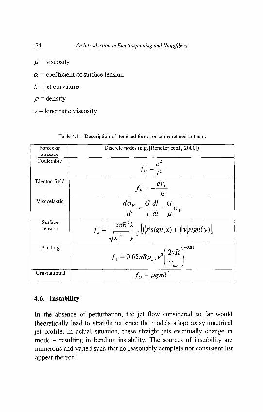
174 An Introduction to Electrospinning and Nanofibers
ju = viscosity
a = coefficient of surface tension
k = jet curvature
p = density
v = kinematic viscosity
Table 4.1. Description of itemized forces or terms related to them.
Forces or Discrete nodes (e.g. [Reneker et al., 2000])stresses
Coulombic 2f - e
,2
Electric field o y
h hviscoelastic dov Gdl G
~dt~~ l~d~C~yGv
Surface anR2k \ 1tension fs - ^ ^ [i|x|szg«(x) + j|j;|j/gn(3;)J
4xt +ytAir drag / y"-"
fA=0.65,RPaiy MVVair)
Gravitational y ^ = ^ ^ 2
4.6. Instability
In the absence of perturbation, the jet flow considered so far wouldtheoretically lead to straight jet since the models adopt axisymmetricaljet profile. In actual situation, these straight jets eventually change inmode - resulting in bending instability. The sources of instability arenumerous and varied such that no reasonably complete nor consistent listappear thereof.
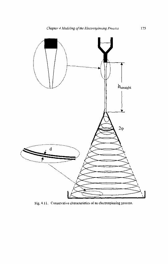
Chapter 4 Modeling of the Electrospinning Process 175
Fig. 4.11. Conservative characteristics of an electrospinning process.
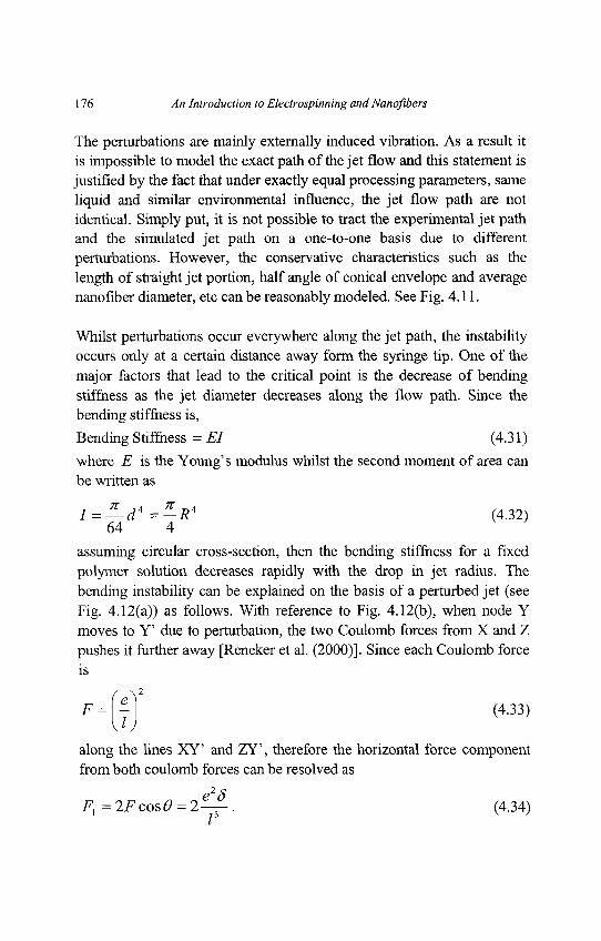
176 An Introduction to Electrospinning and Nanofibers
The perturbations are mainly externally induced vibration. As a result itis impossible to model the exact path of the jet flow and this statement isjustified by the fact that under exactly equal processing parameters, sameliquid and similar environmental influence, the jet flow path are notidentical. Simply put, it is not possible to tract the experimental jet pathand the simulated jet path on a one-to-one basis due to differentperturbations. However, the conservative characteristics such as thelength of straight jet portion, half angle of conical envelope and averagenanofiber diameter, etc can be reasonably modeled. See Fig. 4.11.
Whilst perturbations occur everywhere along the jet path, the instabilityoccurs only at a certain distance away form the syringe tip. One of themajor factors that lead to the critical point is the decrease of bendingstiffness as the jet diameter decreases along the flow path. Since thebending stiffness is,
Bending Stiffness = El (4.31)
where E is the Young's modulus whilst the second moment of area canbe written as
I = ̂ -d*=-R4 (4.32)
64 4assuming circular cross-section, then the bending stiffness for a fixedpolymer solution decreases rapidly with the drop in jet radius. Thebending instability can be explained on the basis of a perturbed jet (seeFig. 4.12(a)) as follows. With reference to Fig. 4.12(b), when node Ymoves to Y' due to perturbation, the two Coulomb forces from X and Zpushes it further away [Reneker et al. (2000)]. Since each Coulomb forceis
F = il] (4'33)along the lines XY' and ZY', therefore the horizontal force componentfrom both coulomb forces can be resolved as
e2SF^=2FcosO = 2—^. (4.34)
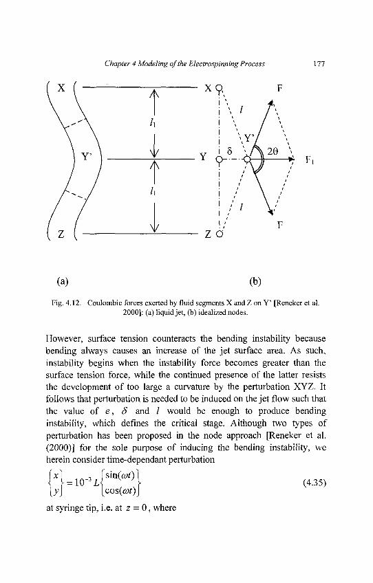
Chapter 4 Modeling of the Electrospinning Process 177
Fig. 4.12. Coulombic forces exerted by fluid segments XandZ on Y' [Reneker et al.2000]: (a) liquid jet, (b) idealized nodes.
However, surface tension counteracts the bending instability becausebending always causes an increase of the jet surface area. As such,instability begins when the instability force becomes greater than thesurface tension force, while the continued presence of the latter resiststhe development of too large a curvature by the perturbation XYZ. Itfollows that perturbation is needed to be induced on the jet flow such thatthe value of e, 8 and / would be enough to produce bendinginstability, which defines the critical stage. Although two types ofperturbation has been proposed in the node approach [Reneker et al.(2000)] for the sole purpose of inducing the bending instability, weherein consider time-dependant perturbation
\ = 10~3L V J\ (4.35)
at syringe tip, i.e. at z = 0, where
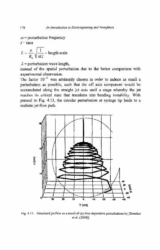
178 An Introduction to Electrospinning and Nanoflbers
co = perturbation frequencyt= time
e [YL = — , = length scaleR0\nG
X = perturbation wave length,instead of the spatial perturbation due to the better comparison withexperimental observation.The factor 10~3 was arbitrarily chosen in order to induce as small aperturbation as possible, such that the off axis component would beaccumulated along the straight jet axis until a stage whereby the jetreaches its critical state that translates into bending instability. Withperusal to Fig. 4.13, the circular perturbation at syringe tip leads to arealistic jet flow path.
Fig. 4.13. Simulated jet flow as a result of (a) time-dependent perturbations by [Renekeret al. (2000)].
Chapter 4 Modeling of the Electrospinning Process 179
In the model by [Hohman et al. (2001a)], 3 different sources ofinstabilities were identified: (i) axisymmetric Rayleigh instability, (ii)electric field induced axisymmetric instability, and (iii) bendinginstability. This approach can be said to be comprehensive in that allinstabilities imaginable were accounted for. Perturbation has beenincorporated into the jet radius, jet velocity, electric field and surfacecharge density by introducing a complex number exp[a>t + ikx][Hohman et al. (2001a)]. However, the bending jet flow path was notsimulated.
4.7. Results
The simulated results were understandably influenced by the purposewhich the modeling works were done. The theoretical treatment by [Feng(2002 & 2003)] allowed the description of jet radius as a function ofdownward vertical axis ( z ) , Reynolds number (Re), Electric Pecletnumber (Pe), ratio of electrostatic force to inertia (Fe/I), Deborah number(De) and flow index (n) among others. This flow index, n, is definedfrom the flow constitutive equation described in Equation (4.10) (see Fig.4.14 (a)-(d)).
Despite of the discrepancy observed between experiment and theory[Reneker et al. (2000)], the theoretical foundation is nevertheless sound.This can be inferred from the fact that when evaporation andsolidification aretaken into consideration, the jet flow path is shown to bemore realistic, as evident in Fig. 4.15 [Yarin et al. (2001a)].
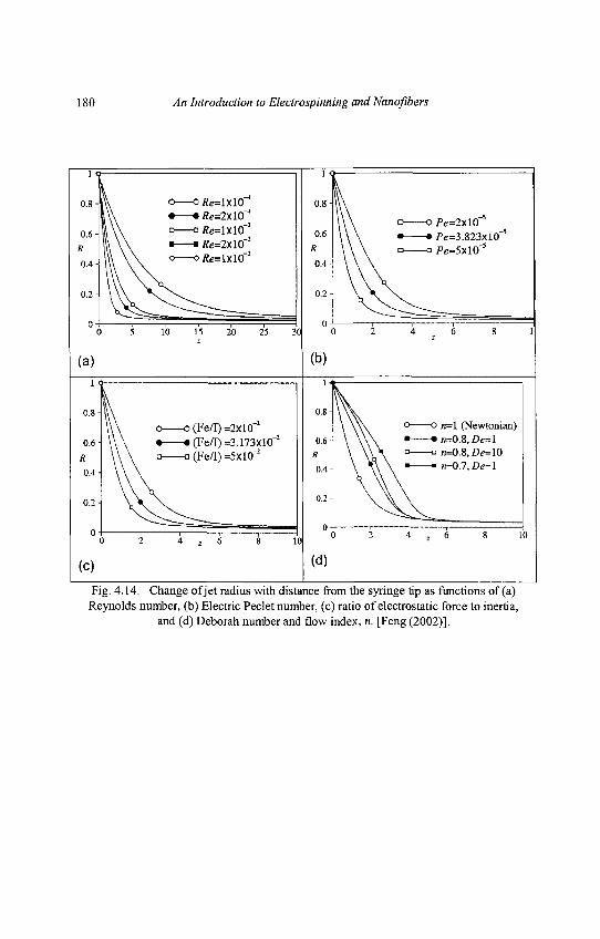
180 An Introduction to Electrospinning and Nanofibers
Fig. 4.14. Change of jet radius with distance from the syringe tip as functions of (a)Reynolds number, (b) Electric Peclet number, (c) ratio of electrostatic force to inertia,
and (d) Deborah number and flow index, n. [Feng (2002)].
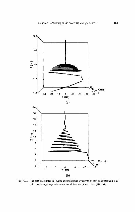
Chapter 4 Modeling of the Electrospinning Process 181
Fig. 4.15. Jet path calculated (a) without considering evaporation and solidification, and(b) considering evaporation and solidification [Yarin et al. (2001a)].
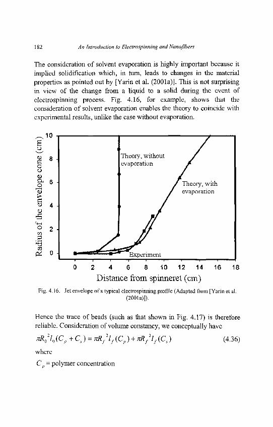
182 An Introduction to Electrospinning and Nanofibers
The consideration of solvent evaporation is highly important because itimplied solidification which, in turn, leads to changes in the materialproperties as pointed out by [Yarin et al. (2001a)]. This is not surprisingin view of the change from a liquid to a solid during the event ofelectrospinning process. Fig. 4.16, for example, shows that theconsideration of solvent evaporation enables the theory to coincide withexperimental results, unlike the case without evaporation.
Fig. 4.16. Jet envelope of a typical electrospinning profile (Adapted from [Yarin et al.(2001a)]).
Hence the trace of beads (such as that shown in Fig. 4.17) is thereforereliable. Consideration of volume constancy, we conceptually have
TTR0210 (Cp +CS) = nRf
2lf (Cp) + nRf2lf (C,) (4.36)
where
Cp = polymer concentration
Chapter 4 Modeling of the Electrospinning Process 183
Cs = solvent concentration
.#„ = initial jet radius
Rf = final fiber radius
l0 = initial length of jet segment
lf = final length of fiber segment.
Practically, the second term on the RHS of Equation (4.36) refers to thevolume of solvent that evaporates. Hence the final fiber's segmentvolume is smaller than its corresponding jet volume, and that, bycanceling the evaporated term, the ratio of final-to-initial volume wouldsimply give the polymer concentration
c'-ixiYBy the knowledge of the polymer concentration during experimentalpreparation Cp , syringe inner radius Ro as determined by the equipmentset-up, and the prescribed initial distance between nodes l0, one canobtain the fiber radius R, upon obtaining the computed final distancebetween nodes / , .
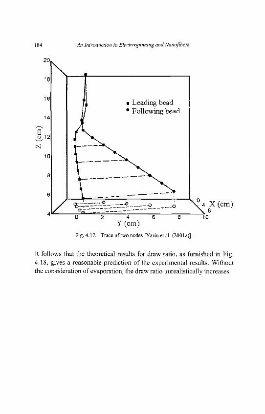
184 An Introduction to Electrospinning and Nanoflbers
Fig. 4.17. Trace of two nodes [Yarin et al. (2001a)].
It follows that the theoretical results for draw ratio, as furnished in Fig.4.18, gives a reasonable prediction of the experimental results. Withoutthe consideration of evaporation, the draw ratio unrealistically increases.
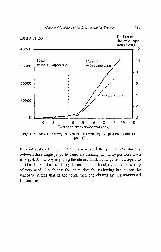
Chapter 4 Modeling of the Electrospinning Process 185
Fig. 4.18. Draw ratio during the event of electrospinning (Adapted from Yarin et al.[2001a]).
It is interesting to note that the viscosity of the jet changes abruptlybetween the straight jet portion and the bending instability portion shownin Fig. 4.19, thereby implying the almost sudden change from a liquid tosolid at the point of instability. If, on the other hand, the rise of viscosityof very gradual such that the jet reaches the collecting late before theviscosity attains that of the solid, then one obtains the interconnectedfibrous mesh.
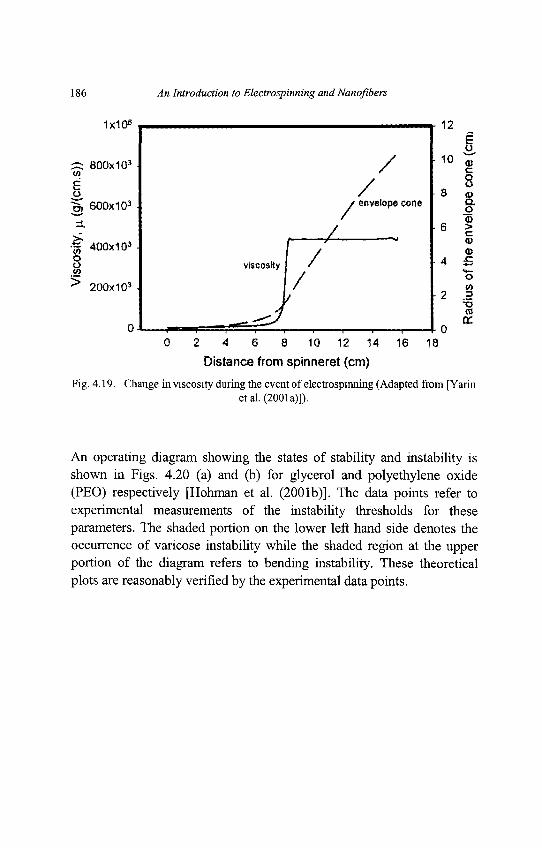
186 An Introduction to Electrospinning and Nanofibers
Fig. 4.19. Change in viscosity during the event of electrospinning (Adapted from [Yarinetal. (2001a)]).
An operating diagram showing the states of stability and instability isshown in Figs. 4.20 (a) and (b) for glycerol and polyethylene oxide(PEO) respectively [Hohman et al. (2001b)]. The data points refer toexperimental measurements of the instability thresholds for theseparameters. The shaded portion on the lower left hand side denotes theoccurrence of varicose instability while the shaded region at the upperportion of the diagram refers to bending instability. These theoreticalplots are reasonably verified by the experimental data points.
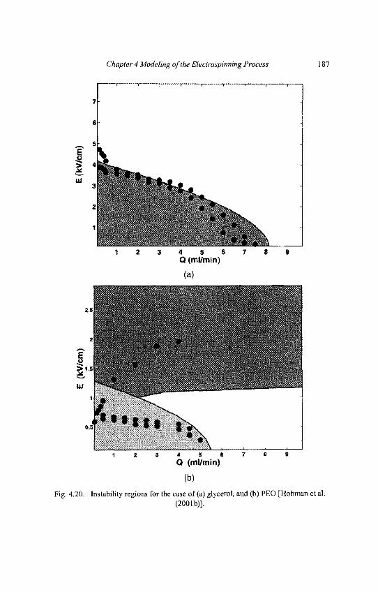
Chapter 4 Modeling of the Electrospinning Process 187
Fig. 4.20. Instability regions for the case of (a) glycerol, and (b) PEO [Hohman et al.(2001b)].
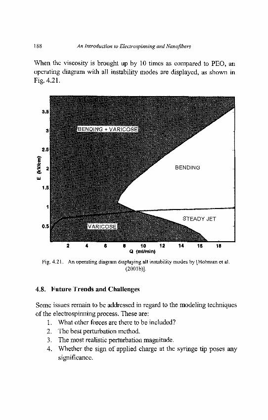
188 An Introduction to Electrospinning and Nanofibers
When the viscosity is brought up by 10 times as compared to PEO, anoperating diagram with all instability modes are displayed, as shown inFig. 4.21.
Fig. 4.21. An operating diagram displaying all instability modes by [Hohman et al.(2001b)].
4.8. Future Trends and Challenges
Some issues remain to be addressed in regard to the modeling techniquesof the electrospinning process. These are:
1. What other forces are there to be included?2. The best perturbation method.3. The most realistic perturbation magnitude.4. Whether the sign of applied charge at the syringe tip poses any
significance.
Chapter 4 Modeling of the Electrospinning Process 189
With the advancement of the electrospinning process and application ofthe electrospun nanofibers, fabrication of advanced nanofibers are beingattempted by means of novel electrospinning processes. Towards thisend, the challenges ahead would be of the following:
4.8.1. Jet Flow With Particles
Electrospinning of polymer solution that contains solid particulates arisesdue to the need to embed the nanofibers with fillers in order to cater forhigher strength, for development of sensor devices and for incorporatingmedicine and nutrients. The existence of particulates will inevitably alterthe overall liquid viscoelastic properties. Additionally, the presence ofnano-scale particulates will require new understanding on their influenceto the effective properties and performance of the electrospun nanofibers.
4.8.2. Core-shell Flow
This electrospinning of concentric jet solution process was introduced inorder to produce core-shell nanofibers and tubular nanofibers. Theformer is important for the use of nanofibers to deliver time-delayeddrugs whilst the latter for nano-scale transport. Tubular nanofibers areobtained when the core material degrades with the passage of time. Withthe flow of two concentrically distinct liquid, it is expected that theoverall jet properties are changed. A challenge for the core-shell andtubular nanofibers is the attainment of consistent shell thickness (orfunctionally graded shell thickness along the longitude if it so desires) aswell as the prevention of shell collapse for the tubular nanofibers.
190 An Introduction to Electrospinning and Nanoflbers
4.8.3. Field-assisted Flow
So far the process modeling has been confined to cases whereby therenanoflbers are collected in a random network. Where alignment ofnanoflbers are required, the use of rotating disk and pair conductors ascollector will definitely induce stretching and change in electric fieldrespectively. Along this direction of thought, the use of electric field tocontrol the jet path for attaining patterned nanofibrous structure has beenshown to be technically feasible [Li et al. (2004b)].
4.8.4. Multi-jet Flow
In the multi-jet electrospinning, multi-spinnerets are used to increase thenumber of jets for high volume production of electrospun nanoflbers.Alternatively multi-jet flow can also be performed by needlelessapproach whereby the polymer solution is electrically forced towards theupward direction. The formation of several Taylor cones on the surfaceof the polymer container determines the number of simultaneous jetflow. The use of multi-spinneret, however, gives greater controllabilityas the number of simultaneous jet flow is determined by the number ofspinerettes. The mechanics of multi-spinneret electrospinning will differfrom that of single syringe electrospinning due to changes in the electricfield and jet overlap.
4.8.5. Gas-assisted flow
In the gas-assisted flow process, gas flows parallel to the straight portionof the jet in the region concentrically surrounding the jet. It is believedthat the jet flow will be more controllable and that the locus ofnanofibrous membrane on the collection plate will be more defined. Theinfluence of aerodynamic forces could be more significant and, if so, themechanics of the jet flow will be altered.
Chapter 4 Modeling of the Electrospinning Process 191
4.9. Conclusions
As a consequence of the different assumptions and methods, weappreciate the fact that all these models are useful in one way or another.The node model and bending instability [Reneker et al. (2000); Yarin etal. (2001a)] is able to give the jet path and, therefore, would berecommended for experimentalist to design their experiments to controlthe collection area of electrospun nanofibers. The combined varicose andbending instability model [Hohman et al. (2001a & 2001b)] has beendemonstrated to be reliable for predicting the instability modes of the jetusing fluid properties and process parameters. It follows, then, that the jetstability can be controlled by refining the process parameters andcarefully choosing the polymer for the desired fluid electro-rheologicalproperties.
A selection of modeling methods for the electrospinning process hasbeen briefly surveyed and their corresponding results have been given.Currently, two schools of thought are applicable on the basis of the jetconceptualization - continuous media and discrete nodes. In summary,the main concepts adopted are those of conservation laws (such as theconservation of mass, charge and momentum) and Newton's SecondLaw of motion. The latter concept enables the acceleration of jet can beobtained by considering the various forces acting on the jet, such asCoulombic, electric field, surface tension, viscoelastic forces, etc. Thereis also a need to assume the viscoelastic properties of the polymersolution in order to apply its constitutive relations.
Chapter 5
Characterization
Electrospun polymer nanofibers in the form of membrane have manypotential applications in the field of bioengineering, environmentalengineering & biotechnology, energy & electronics, and defense &security, as introduced in chapter 7. The explanation of specificcharacterization on each application is omitted here. However, it must beborne in mind that the basic properties of nanofibrous membranes are (1)morphology, (2) molecular structure and (3) mechanical properties. Themorphology of single fiber such as average fiber diameter, pores on thefiber surface as well as the morphology of nanofibrous membrane suchas porosity, are basic properties of the deposited nanofibers on thecollector. Hydrophobic property is also related to the morphology of thenanofiber and nanofibrous membrane. The molecular structure of ananofiber bears influence on the optical, thermal and mechanicalbehavior of the nanofibrous membranes. If these nanofibrous membranesare chemically treated after the spinning process, we are interested in thechange of chemical structure of the polymer molecules. Mechanicalproperties of single nanofiber as well as nanofibrous membranes areimportant because without mechanical stability, the nanofibrousmembranes cannot be sued in the abovementioned applications. Thischapter introduces to the readers the various characterization techniquesfor obtaining each physical property.
192
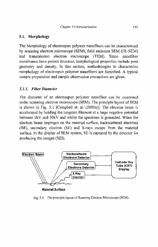
Chapter 5 Characterization 193
5.1. Morphology
The Morphology of electrospun polymer nanofibers can be characterizedby scanning electron microscope (SEM), field emission SEM (FE-SEM)and transmission electron microscope (TEM). Since nanofibermembranes have porous structure, morphological properties include poregeometry and density. In this section, methodologies to characterizemorphology of electrospun polymer nanofibers are furnished. A typicalsample preparation and sample observation precautions are given.
5.7.7. Fiber Diameter
The diameter of an electrospun polymer nanofiber can be examinedunder scanning electron microscope (SEM). The principle layout of SEMis shown in Fig. 5.1 [Campbell et. al. (2000a)]. The electron beam isaccelerated by holding the tungsten filament at a large negative potentialbetween lkV and 50kV and whilst the specimen is grounded. When theelectron beam impinges on the material surface, backscattered electrons(BE), secondary electron (SE) and X-rays escape from the materialsurface. In the display of SEM system, SE is captured by the detector forproducing the images (SEI).
Fig. 5.1. The principle layout of Scanning Electron Microscope (SEM).
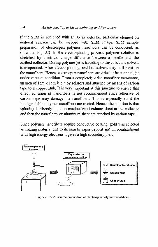
194 An Introduction to Electrospinning andNanofibers
If the SEM is equipped with an X-ray detector, particular element onmaterial surface can be mapped with SEM image. SEM samplepreparation of electrospun polymer nanofibers can be conducted, asshown in Fig. 5.2. In the electrospinning process, polymer solution isstretched by electrical charge difference between a needle and theearthed collector. During polymer jet is traveling to the collector, solventis evaporated. After electrospinning, residual solvent may still exist onthe nanofibers. Hence, electrospun nanofibers are dried at least one nightunder vacuum condition. From a completely dried nanofiber membrane,an area of lcm x lcm is cut by scissors and attached by means of carbontape to a copper stub. It is very important at this juncture to ensure thatdirect adhesion of nanofibers is not recommended since adhesive ofcarbon tape may damage the nanofibers. This is especially so if thebiodegradable polymer nanofibers are treated. Hence, the solution is thatspinning is directly done on conductive aluminum sheet at the collectorand then the nanofibers on aluminum sheet are attached by carbon tape.
Since polymer nanofibers require conductive coating, gold was selectedas coating material due to its ease to vapor deposit and on bombardmentwith high energy electrons it gives a high secondary yield.
Fig. 5.2. SEM sample preparation of electrospun polymer nanofibers.
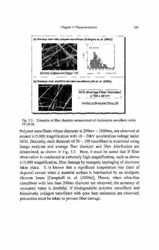
Chapter 5 Characterization 195
Fig. 5.3. Examples of fiber diameter measurement of electrospun nanofibers underFE-SEM.
Polymer nanofibers whose diameter is 200nm ~ 1 OOOnm, are observed ataround x 15,000 magnification with 10 ~ 20kV acceleration voltage underSEM. Basically, each diameter of 50 ~ 100 nanofibers is examined usingimage analyzer and average fiber diameter and fiber distribution aredetermined, as shown in Fig. 5.3. Here, it must be noted that if fiberobservation is conducted at extremely high magnification, such as abovexl 5,000 magnification, fiber damage by energetic impinging of electronstakes place. It is known that a significant temperature rise (tens ofdegrees) occurs when a material surface is bombarded by an energeticelectron beam [Campbell et. al. (2000a)]. Hence, when ultra-finenanofibers with less than 200nm diameter are observed, the accuracy ofmeasured value is doubtful. If biodegradable polymer nanofibers andbiomimetic collagen nanofibers with poor heat resistance are observed,precaution must be taken to prevent fiber damage.
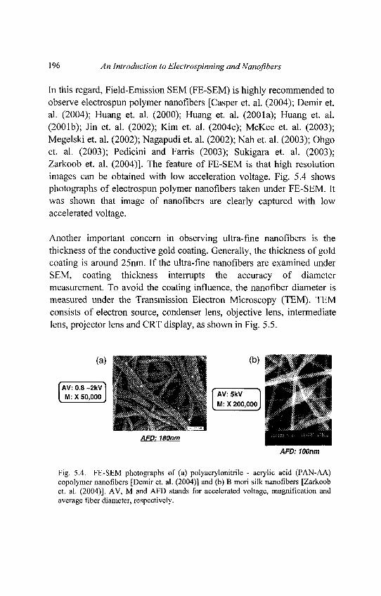
196 An Introduction to Electrospinning andNanofibers
In this regard, Field-Emission SEM (FE-SEM) is highly recommended toobserve electrospun polymer nanofibers [Casper et. al. (2004); Demir et.al. (2004); Huang et. al. (2000); Huang et. al. (2001a); Huang et. al.(2001b); Jin et. al. (2002); Kim et. al. (2004e); McKee et. al. (2003);Megelski et. al. (2002); Nagapudi et. al. (2002); Nah et. al. (2003); Ohgoet. al. (2003); Pedicini and Farris (2003); Sukigara et. al. (2003);Zarkoob et. al. (2004)]. The feature of FE-SEM is that high resolutionimages can be obtained with low acceleration voltage. Fig. 5.4 showsphotographs of electrospun polymer nanofibers taken under FE-SEM. Itwas shown that image of nanofibers are clearly captured with lowaccelerated voltage.
Another important concern in observing ultra-fine nanofibers is thethickness of the conductive gold coating. Generally, the thickness of goldcoating is around 25nm. If the ultra-fine nanofibers are examined underSEM, coating thickness interrupts the accuracy of diametermeasurement. To avoid the coating influence, the nanofiber diameter ismeasured under the Transmission Electron Microscopy (TEM). TEMconsists of electron source, condenser lens, objective lens, intermediatelens, projector lens and CRT display, as shown in Fig. 5.5.
Fig. 5.4. FE-SEM photographs of (a) polyacrylonitrile - acrylic acid (PAN-AA)copolymer nanofibers [Demir et. al. (2004)] and (b) B mori silk nanofibers [Zarkoobet. al. (2004)]. AV, M and AFD stands for accelerated voltage, magnification andaverage fiber diameter, respectively.
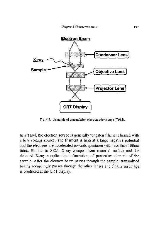
Chapter 5 Characterization 197
Fig. 5.5. Principle of transmission electron microscope (TEM).
In a TEM, the electron source is generally tungsten filament heated witha low voltage source. The filament is held at a large negative potentialand the electrons are accelerated towards specimen with less than 1 OOnmthick. Similar to SEM, X-ray escapes from material surface and thedetected X-ray supplies the information of particular element of thesample. After the electron beam passes through the sample, transmittedbeams accordingly passes through the other lenses and finally an imageis produced at the CRT display.
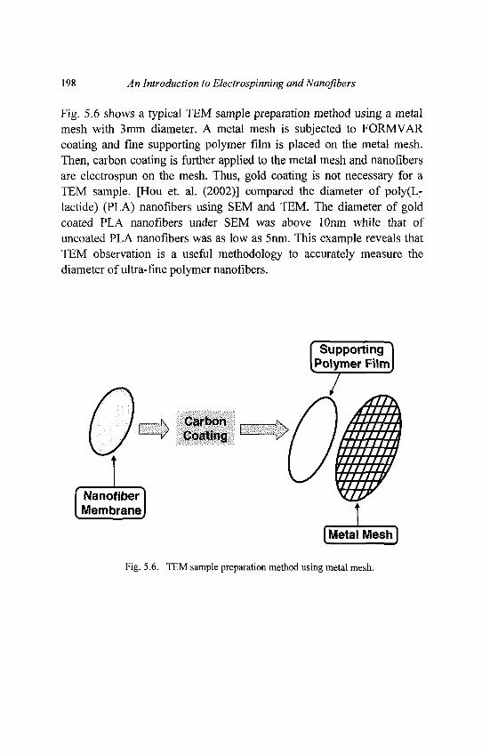
198 An Introduction to Electrospinning andNanofibers
Fig. 5.6 shows a typical TEM sample preparation method using a metalmesh with 3mm diameter. A metal mesh is subjected to FORMVARcoating and fine supporting polymer film is placed on the metal mesh.Then, carbon coating is further applied to the metal mesh and nanofibersare electrospun on the mesh. Thus, gold coating is not necessary for aTEM sample. [Hou et. al. (2002)] compared the diameter of poly(L-lactide) (PLA) nanofibers using SEM and TEM. The diameter of goldcoated PLA nanofibers under SEM was above lOnm while that ofuncoated PLA nanofibers was as low as 5nm. This example reveals thatTEM observation is a useful methodology to accurately measure thediameter of ultra-fine polymer nanofibers.
Fig. 5.6. TEM sample preparation method using metal mesh.
Chapter 5 Characterization 199
5.1.2. Pore Size and Porosity
Pores play an important role in determining the physical and chemicalproperties of porous substrates and have a deterministic effect on theperformance of membranes, catalysts, adsorbents etc. To designelectrospun nanofibrous substrates for such applications, it is necessaryto analyze the pore-size, its distribution and porosity. In electrospunnanofibrous substrates, two types of pores can be identified: (1) poreson/within each fiber and (2) pores (between fibers) on a nanofibrousmembrane. Pore size can be measured by direct or indirect methods.Direct methods involve the use of techniques such as electronmicroscopy (SEM and TEM) or atomic force microscopy (AFM). Boththese techniques can provide detailed and magnified 'images' of theelectrospun nanofibers from which pore size and its distribution can bedetermined. Indirect methods include bubble point measurements, soluteretention challenge, molecular resolution porosimetry, extrusionporosimetry and instrusion porosimetry.
Pores on the Surface of Electrospun Fibers
Fig. 5.7 shows poly(L-lactic acid) (PLLA) electrospun fibers having aporous surface structure. These features may also extend to the interior ofthe fiber (see in Fig. 5.8), as observed by the cross-sectional micrographof electrospun polysulfone (PSU) fibers. Such structures are very uniqueand may be useful for drug release applications. As an example, weconsider a core region of the nanofiber being filled with a drug elementwhile the shell region of the nanofiber has a porous structure. In thisarrangement, the nanofiber becomes a drug-carrying component,whereby the drugs can be released to the surroundings through theporous shell region. As such, drug release rate of nanofibers is definitelyinfluenced by the surface pore size as well as porosity of the fiber.Hence, pore size, its distribution and porosity on single fibers areimportant parameters.
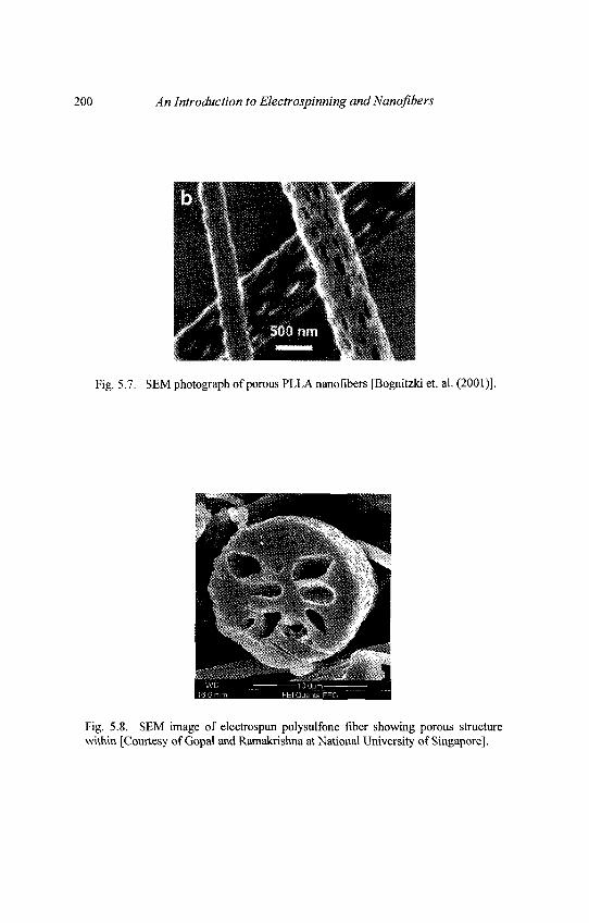
200 An Introduction to Electrospinning and Nanofibers
Fig. 5.7. SEM photograph of porous PLLA nanofibers [Bognitzki et. al. (2001)].
Fig. 5.8. SEM image of electrospun polysulfone fiber showing porous structurewithin [Courtesy of Gopal and Ramakrishna at National University of Singapore].
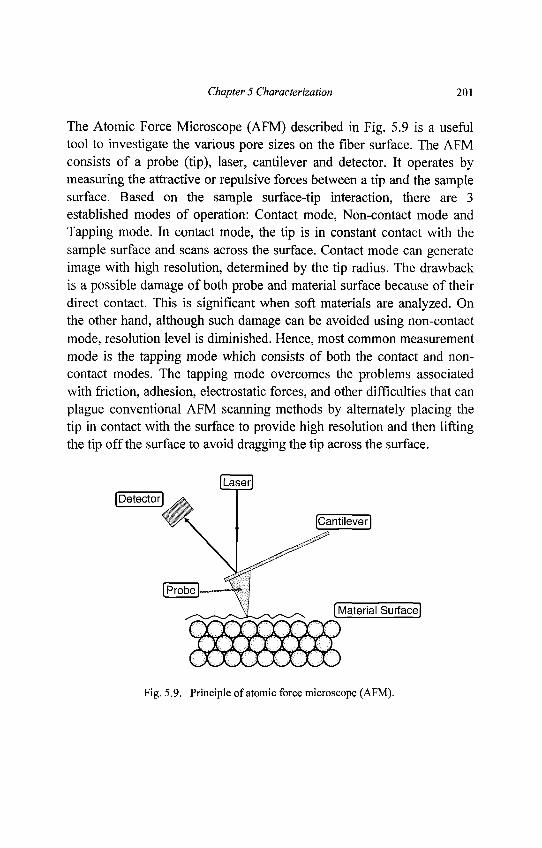
Chapter 5 Characterization 201
The Atomic Force Microscope (AFM) described in Fig. 5.9 is a usefultool to investigate the various pore sizes on the fiber surface. The AFMconsists of a probe (tip), laser, cantilever and detector. It operates bymeasuring the attractive or repulsive forces between a tip and the samplesurface. Based on the sample surface-tip interaction, there are 3established modes of operation: Contact mode, Non-contact mode andTapping mode. In contact mode, the tip is in constant contact with thesample surface and scans across the surface. Contact mode can generateimage with high resolution, determined by the tip radius. The drawbackis a possible damage of both probe and material surface because of theirdirect contact. This is significant when soft materials are analyzed. Onthe other hand, although such damage can be avoided using non-contactmode, resolution level is diminished. Hence, most common measurementmode is the tapping mode which consists of both the contact and non-contact modes. The tapping mode overcomes the problems associatedwith friction, adhesion, electrostatic forces, and other difficulties that canplague conventional AFM scanning methods by alternately placing thetip in contact with the surface to provide high resolution and then liftingthe tip off the surface to avoid dragging the tip across the surface.
Fig. 5.9. Principle of atomic force microscope (AFM).
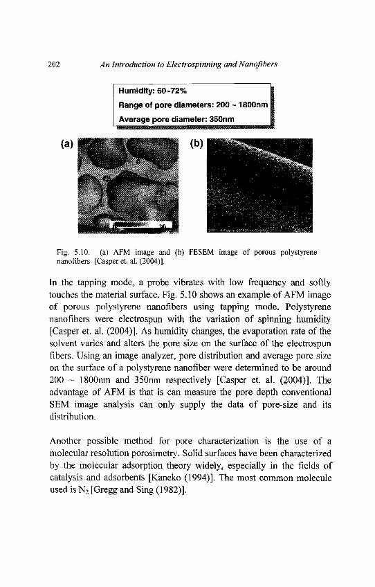
202 An Introduction to Electrospinning and Nanofibers
Fig. 5.10. (a) AFM image and (b) FESEM image of porous polystyrenenanofibers [Casper et. al. (2004)].
In the tapping mode, a probe vibrates with low frequency and softlytouches the material surface. Fig. 5.10 shows an example of AFM imageof porous polystyrene nanofibers using tapping mode. Polystyrenenanofibers were electrospun with the variation of spinning humidity[Casper et. al. (2004)]. As humidity changes, the evaporation rate of thesolvent varies and alters the pore size on the surface of the electrospunfibers. Using an image analyzer, pore distribution and average pore sizeon the surface of a polystyrene nanofiber were determined to be around200 ~ 1800nm and 350nm respectively [Casper et. al. (2004)]. Theadvantage of AFM is that is can measure the pore depth conventionalSEM image analysis can only supply the data of pore-size and itsdistribution.
Another possible method for pore characterization is the use of amolecular resolution porosimetry. Solid surfaces have been characterizedby the molecular adsorption theory widely, especially in the fields ofcatalysis and adsorbents [Kaneko (1994)]. The most common moleculeused is N2 [Gregg and Sing (1982)].
Chapter 5 Characterization 203
When a surface is exposed to a gaseous environment, gas molecules getadsorbed onto the surface due to the weak van der Waal's typeinteraction between the surface and the molecules. At constanttemperature, the amount of adsorbed gas on a surface depends on thepressure of the gas. Measurement of the amount of adsorption as afunction of pressure can give information on the pore structure. TheBrunauer Emmett and Teller (BET) theory of physical adsorption isnormally used for analysis of adsorption data [Brunauer et. al. (1938)].The advantage of using a BET analyzer is that it can determine theporosity and the surface area of the substrate on top of pore size and itsdistribution. To date such methods have not been employed on surfacecharacterization of electrospun fibers. It should be possible to use thistechnique. The only limitation of this method is that the measuredmaximum pore size is around 200 nm. Hence it is only suitable for fibersurface analysis and not for membranes.
Pores on Electrospun Nanofibrous Membranes
Fig. 5.11 shows that electrospun nanofibrous membranes possessinterstitial spaces between fibers. These are analogous to the porespresent in membranes. Thus through electrospinning a highly porousmembrane can be generated. In separation technology, the knowledge ofpore size and porosity are critical in determining the membrane'sperformance. Pore size discriminates between the type (size ormolecular weight) of species than can permeate through and which willbe retained; whereas porosity determines the flux or flow across themembrane. Just like in surface pore analysis, SEM can be used todetermine the pore size of electrospun nanofibrous membranes.However, porosity cannot be measured by SEM. Further disadvantage isthat only pores on the top surface can be analyzed while pores beneaththe membrane surface cannot be directly determined.
The most common methodology adopted for membrane porecharacterization is using mercury porosimetry. The principle of mercuryporosimeter is shown in Fig. 5.12.
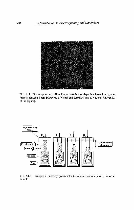
204 An Introduction to Electrospinning and Nanoftbers
Fig. 5.11. Electrospun polysulfon fibrous membrane, depicting interstitial spaces(pores) between fibers [Courtesy of Gopal and Ramakrishna at National Universityof Singapore].
Fig. 5.12. Principle of mercury porosimeter to measure various pore sizes of asample.
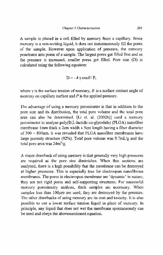
Chapter 5 Characterization 205
A sample is placed in a cell filled by mercury from a capillary. Sincemercury is a non-wetting liquid, it does not instantaneously fill the poresof the sample. However upon application of pressure, the mercurypenetrates into pores of a sample. The largest pores get filled first and asthe pressure is increased, smaller pores get filled. Pore size (D) iscalculated using the following equation:
D = -4ycos<9/P,
where y is the surface tension of mercury, 0 is a surface contact angle ofmercury on capillary surface and P is the applied pressure.
The advantage of using a mercury porosimeter is that in addition to thepore size and its distribution, the total pore volume and the total porearea can also be determined. [Li et. al. (2002b)] used a mercuryporosimeter to analyze poly(D,L-lactide-co-glycolide) (PLGA) nanofibermembrane lmm thick x 2cm width x 5 cm length having a fiber diameterof 500 ~ 800nm. It was revealed that PLGA nanofiber membranes havelarge porosity structure (92%). Total pore volume was 9.7mL/g and thetotal pore area was 24m2/g.
A major drawback of using mercury is that generally very high pressuresare required as the pore size diminishes. When thin sections areanalyzed, there is a high possibility that the membrane can be destroyedat higher pressures. This is especially true for electrospun nanofibrousmembranes. The pores in electrospun membrane are 'dynamic' in nature;they are not rigid pores and self-supporting structures. For successfulmercury porosimetry analysis, thick samples are necessary. Whensamples less than lOOjim are used, they are destroyed by the pressure.The other drawbacks of using mercury are its cost and toxicity. It is alsopossible to use a lower surface tension liquid in place of mercury. Inprinciple, any liquid that does not wet the membrane spontaneously canbe used and obeys the abovementioned equation.
206 An Introduction to Electrospinning and Nanofibers
By using such liquids, intrusion into pores can be accomplished at muchlower pressures than those required with mercury. This greatly reducesthe risk of the sample being crushed at high pressures.
Alternatively, instead of intrusion porosimetry, extrusion porosimetrycan be employed. In such systems, the sample pores are filled with awetting liquid. The differential pressure of a non-reacting gas isincreased on the sample to displace the liquid from the pores. The liquiddisplace from the pores and the sample is weighed. Using theaforementioned equation, the pore diameter can be determined. Based onthis principle, [Gibson and Gibson (2002)] used a capillary flowporometer, which uses a special low tension fluid, Galden perfluorinatedliquid HT 230, to determine the pore- size of their electrospun Estane®58237. In their study, membranes with only 100)um thickness weresuccessfully characterized. Table 5.1 summarizes the various methodsavailable for pore-size analysis.
5.1.3. Surface Contact Angle Measurement
The hydrophobic (or hydrophilic) nature of a substrate has a directimpact on the avenue of its usage. For example, in membrane distillation,where water must not enter the membrane, a hydrophobic membrane hasto be used. In separation of protein solutions, hydrophilic membranes arepreferred to minimize protein adsorption. Likewise for tissue-engineeringscaffolds hydrophilic scaffolds are preferred. The most direct method ofmeasuring these characteristics is via contact angle measurements.
Surface contact angle of electrospun nanofibrous membranes is simplyexamined by a water contact angle (WCA) machine. A distilled waterpendent droplet is injected from a syringe onto the membrane surface.The image of the droplet on the membrane is visualized through theimage analyzer and the angle between the water droplet and the surfaceis measured. Hydrophilic materials show low contact angle (spreading ofwater across surface) while hydrophobic materials show high contactangle (minimal contact between water droplet and surface).
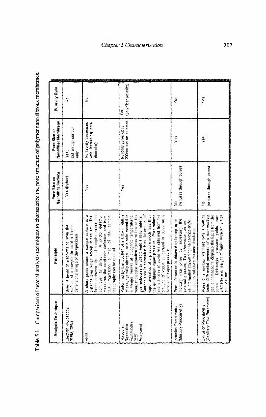
Chapter 5 Characterization 207
Tab
le 5
.1.
Com
paris
on o
f se
vera
l an
alys
is te
chni
ques
to c
hara
cter
ize
the
pore
stru
ctur
e of
pol
ymer
nan
o fib
rous
mem
bran
es.
Ana
lysi
s Te
chni
que
Ele
ctro
n M
icro
scop
y(S
EM
, TE
M)
AF
M
Mol
ecul
arR
esol
utio
nP
oros
imet
ry(B
ET
Ana
lyze
rs)
Intru
sion
Por
osim
etry
(Mer
cury
Por
osim
etry
)
Ext
rusi
on P
oros
imet
ry(C
apilla
ry F
low
Por
omet
er)
Pri
ncip
le
Use
s a
beam
of
elec
trons
to
scan
the
surfa
ce
of a
sa
mpl
e to
bu
ild
a th
ree-
dim
ensi
onal
imag
e of
the
spec
imen
.
A s
harp
pro
be s
cans
a s
ampl
e su
rface
at
adi
stan
ce o
ver
whi
ch a
tom
ic f
orce
s ac
t. Th
efo
rces
be
twee
n tip
an
d sa
mpl
e ca
use
the
cant
ileve
r to
de
flect
. A
ph
oto
dete
ctor
mea
sure
s th
e ca
ntile
ver
defle
ctio
n an
d fro
mth
is
info
rmat
ion
a m
ap
of
the
sam
ple
topo
grap
hy c
an b
e cr
eate
d.
Per
form
ed b
y th
e ad
ditio
n of
a k
now
n vo
lum
eof
gas
, typ
ical
ly n
itrog
en, t
o a
solid
mat
eria
l in
a sa
mpl
e ve
ssel
at
cr
yoge
nic
tem
pera
ture
s,w
eak
mol
ecul
ar a
ttrac
tive
forc
es w
ill c
ause
the
gas
mol
ecul
es t
o ad
sorb
ont
o a
solid
mat
eria
l.S
urfa
ce a
rea
is c
ompu
ted
from
the
am
ount
of
vapo
r ad
sorb
ed a
t a
pres
sure
muc
h le
ss t
han
the
equi
libriu
m v
apor
pre
ssur
e..
Por
e vo
lum
ean
d di
amet
er o
f po
res
are
obta
ined
fro
m t
heam
ount
of
va
por
cond
ense
d in
po
res
as a
func
tion
of v
apor
pre
ssur
e.
Por
e in
form
atio
n is
obt
aine
d by
forc
ing
liqui
dm
ercu
ry
into
po
res
by
incr
easi
ng
the
exte
rnal
pre
ssur
e. T
his
info
rmat
ion,
as
wel
las
info
rmat
ion
conc
erni
ng th
e co
ntac
t an
gle ,
is u
sed
to c
alcu
late
the
pore
stru
ctur
es.
Por
es
of a
sam
ple
are
fille
d w
ith
a w
ettin
gliq
uid.
D
iffer
entia
l pr
essu
re
of a
non
-rea
ctin
gga
s is
incr
ease
d to
dis
plac
e th
e liq
uid
from
the
pore
s.
Diff
eren
tial
pres
sure
yi
elds
po
redi
amet
er a
nd w
eigh
t of
liq
uid
expe
lled
yiel
d spo
re v
olum
e.
Por
e S
ize
onN
anof
iber
Sur
face
Yes
(lim
ited)
Yes
Yes
No
(req
uire
s th
roug
h po
res)
No
(req
uire
s th
roug
h po
res)
Por
e S
ize
onN
anof
iber
Mem
bran
e
Yes
,bu
t on
top
sur
face
only
No (
abili
ty d
ecre
ases
with
in
crea
sing
po
redi
amet
er)
No
(onl
y po
res
up to
200n
m c
an b
e de
tect
ed
Yes
Yes
Por
osity
Rat
e
No
No
Yes
(onl
y fib
er p
oros
ity)
Yes
Yes
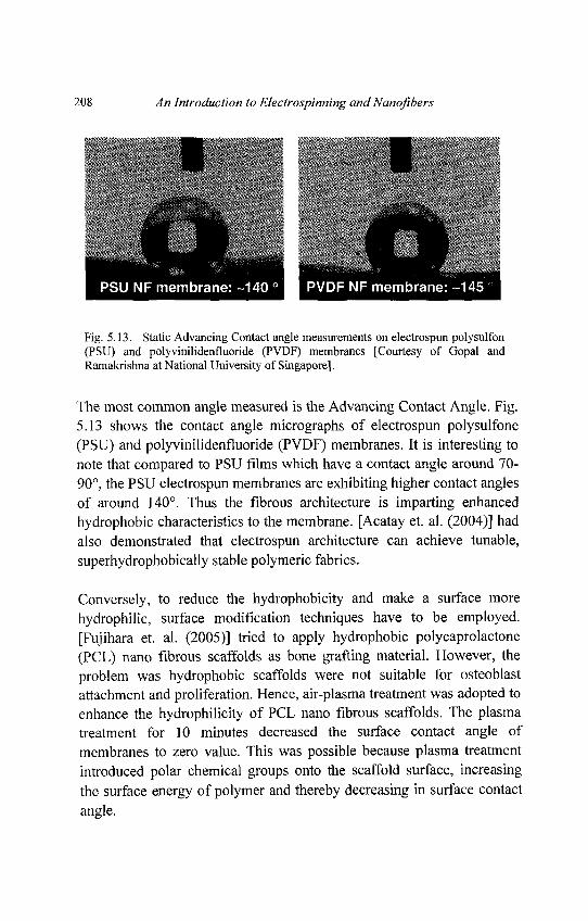
208 An Introduction to Electrospinning and Nanofibers
Fig. 5.13. Static Advancing Contact angle measurements on electrospun polysulfon(PSU) and polyvinilidenfluoride (PVDF) membranes [Courtesy of Gopal andRamakrishna at National University of Singapore].
The most common angle measured is the Advancing Contact Angle. Fig.5.13 shows the contact angle micrographs of electrospun polysulfone(PSU) and polyvinilidenfluoride (PVDF) membranes. It is interesting tonote that compared to PSU films which have a contact angle around 70-90°, the PSU electrospun membranes are exhibiting higher contact anglesof around 140°. Thus the fibrous architecture is imparting enhancedhydrophobic characteristics to the membrane. [Acatay et. al. (2004)] hadalso demonstrated that electrospun architecture can achieve tunable,superhydrophobically stable polymeric fabrics.
Conversely, to reduce the hydrophobicity and make a surface morehydrophilic, surface modification techniques have to be employed.[Fujihara et. al. (2005)] tried to apply hydrophobic polycaprolactone(PCL) nano fibrous scaffolds as bone grafting material. However, theproblem was hydrophobic scaffolds were not suitable for osteoblastattachment and proliferation. Hence, air-plasma treatment was adopted toenhance the hydrophilicity of PCL nano fibrous scaffolds. The plasmatreatment for 10 minutes decreased the surface contact angle ofmembranes to zero value. This was possible because plasma treatmentintroduced polar chemical groups onto the scaffold surface, increasingthe surface energy of polymer and thereby decreasing in surface contactangle.
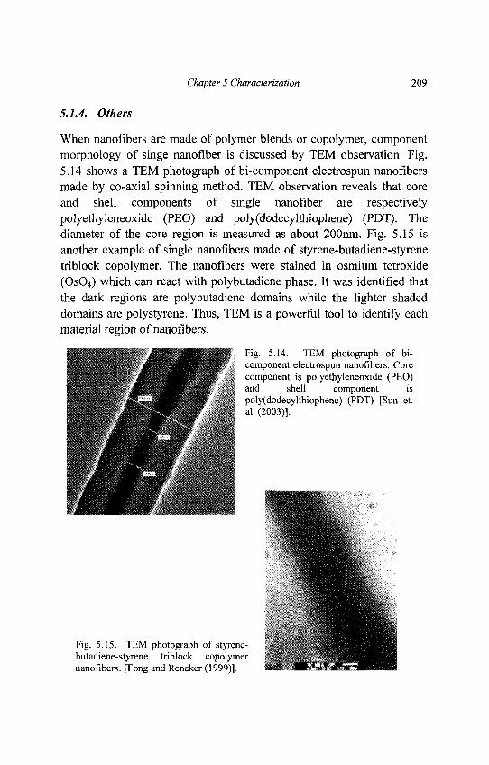
Chapter 5 Characterization 209
5.1.4. Others
When nanofibers are made of polymer blends or copolymer, componentmorphology of singe nanofiber is discussed by TEM observation. Fig.5.14 shows a TEM photograph of bi-component electrospun nanofibersmade by co-axial spinning method. TEM observation reveals that coreand shell components of single nanofiber are respectivelypolyethyleneoxide (PEO) and poly(dodecylthiophene) (PDT). Thediameter of the core region is measured as about 200nm. Fig. 5.15 isanother example of single nanofibers made of styrene-butadiene-styrenetriblock copolymer. The nanofibers were stained in osmium tetroxide(OsO4) which can react with polybutadiene phase. It was identified thatthe dark regions are polybutadiene domains while the lighter shadeddomains are polystyrene. Thus, TEM is a powerful tool to identify eachmaterial region of nanofibers.
Fig. 5.14. TEM photograph of bi-component electrospun nanofibers. Corecomponent is polyethyleneoxide (PEO)and shell component ispoly(dodecylthiophene) (PDT) [Sun et.al. (2003)].
Fig. 5.15. TEM photograph of styrene-butadiene-styrene triblock copolymernanofibers. [Fong and Reneker (1999)].
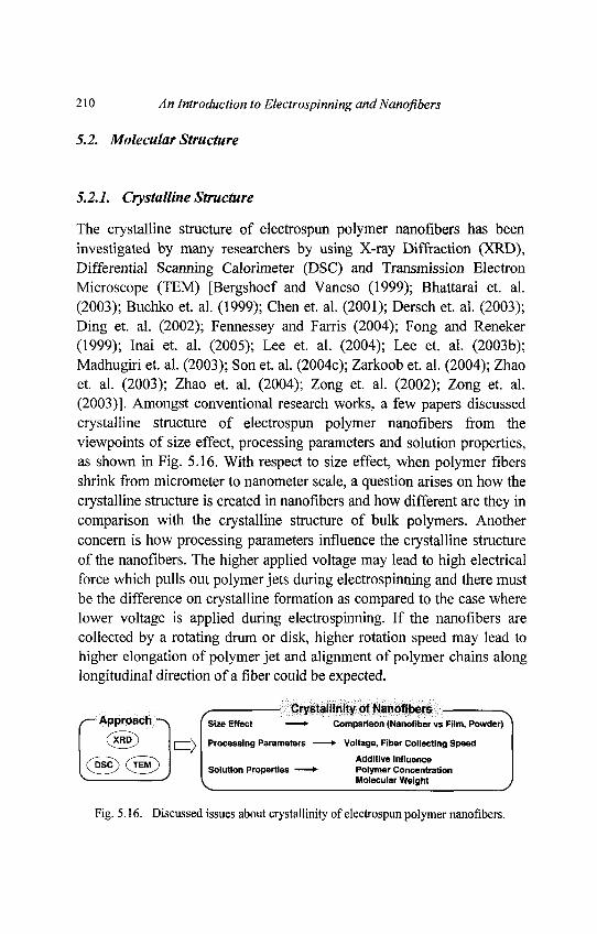
210 An Introduction to Electrospinning and Nanoflbers
5.2. Molecular Structure
5.2.1. Crystalline Structure
The crystalline structure of electrospun polymer nanoflbers has beeninvestigated by many researchers by using X-ray Diffraction (XRD),Differential Scanning Calorimeter (DSC) and Transmission ElectronMicroscope (TEM) [Bergshoef and Vancso (1999); Bhattarai et. al.(2003); Buchko et. al. (1999); Chen et. al. (2001); Dersch et. al. (2003);Ding et. al. (2002); Fennessey and Farris (2004); Fong and Reneker(1999); Inai et. al. (2005); Lee et. al. (2004); Lee et. al. (2003b);Madhugiri et. al. (2003); Son et. al. (2004c); Zarkoob et. al. (2004); Zhaoet. al. (2003); Zhao et. al. (2004); Zong et. al. (2002); Zong et. al.(2003)]. Amongst conventional research works, a few papers discussedcrystalline structure of electrospun polymer nanoflbers from theviewpoints of size effect, processing parameters and solution properties,as shown in Fig. 5.16. With respect to size effect, when polymer fibersshrink from micrometer to nanometer scale, a question arises on how thecrystalline structure is created in nanoflbers and how different are they incomparison with the crystalline structure of bulk polymers. Anotherconcern is how processing parameters influence the crystalline structureof the nanoflbers. The higher applied voltage may lead to high electricalforce which pulls out polymer jets during electrospinning and there mustbe the difference on crystalline formation as compared to the case wherelower voltage is applied during electrospinning. If the nanoflbers arecollected by a rotating drum or disk, higher rotation speed may lead tohigher elongation of polymer jet and alignment of polymer chains alonglongitudinal direction of a fiber could be expected.
Fig. 5.16. Discussed issues about crystallinity of electrospun polymer nanofibers.
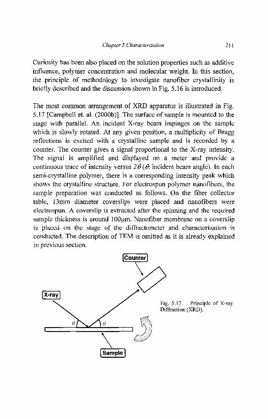
Chapter 5 Characterization 211
Curiosity has been also placed on the solution properties such as additiveinfluence, polymer concentration and molecular weight. In this section,the principle of methodology to investigate nanofiber crystallinity isbriefly described and the discussion shown in Fig. 5.16 is introduced.
The most common arrangement of XRD apparatus is illustrated in Fig.5.17 [Campbell et. al. (2000b)]. The surface of sample is mounted to thestage with parallel. An incident X-ray beam impinges on the samplewhich is slowly rotated. At any given position, a multiplicity of Braggreflections is excited with a crystalline sample and is recorded by acounter. The counter gives a signal proportional to the X-ray intensity.The signal is amplified and displayed on a meter and provide acontinuous trace of intensity versus 26 {&. incident beam angle). In eachsemi-crystalline polymer, there is a corresponding intensity peak whichshows the crystalline structure. For electrospun polymer nanofibers, thesample preparation was conducted as follows. On the fiber collectortable, 13mm diameter coverslips were placed and nanofibers wereelectrospun. A coverslip is extracted after the spinning and the requiredsample thickness is around lOOum. Nanofiber membrane on a coverslipis placed on the stage of the diffractometer and characterization isconducted. The description of TEM is omitted as it is already explainedin previous section.
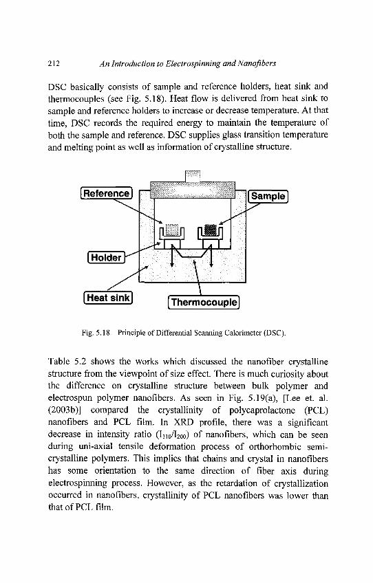
212 An Introduction to Electrospinning and Nanoflbers
DSC basically consists of sample and reference holders, heat sink andthermocouples (see Fig. 5.18). Heat flow is delivered from heat sink tosample and reference holders to increase or decrease temperature. At thattime, DSC records the required energy to maintain the temperature ofboth the sample and reference. DSC supplies glass transition temperatureand melting point as well as information of crystalline structure.
Fig. 5.18. Principle of Differential Scanning Calorimeter (DSC).
Table 5.2 shows the works which discussed the nanofiber crystallinestructure from the viewpoint of size effect. There is much curiosity aboutthe difference on crystalline structure between bulk polymer andelectrospun polymer nanoflbers. As seen in Fig. 5.19(a), [Lee et. al.(2003b)] compared the crystallinity of polycaprolactone (PCL)nanoflbers and PCL film. In XRD profile, there was a significantdecrease in intensity ratio (I110/I200) of nanoflbers, which can be seenduring uni-axial tensile deformation process of orthorhombic semi-crystalline polymers. This implies that chains and crystal in nanoflbershas some orientation to the same direction of fiber axis duringelectrospinning process. However, as the retardation of crystallizationoccurred in nanoflbers, crystallinity of PCL nanoflbers was lower thanthat of PCL film.
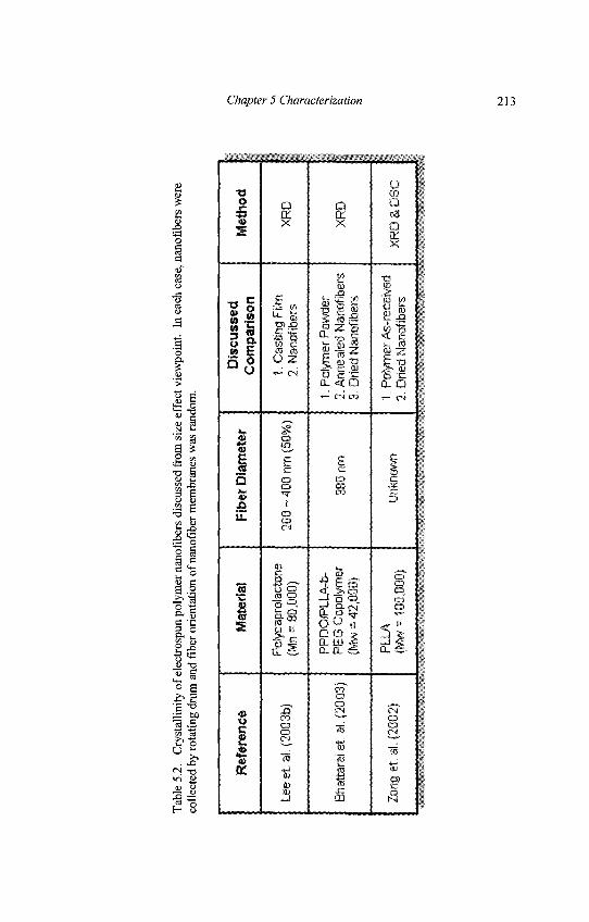
Tab
le 5
.2.
Cry
stal
linity
of
elec
tros
pun
poly
mer
nan
ofib
ers
disc
usse
d fr
om s
ize
effe
ct v
iew
poin
t. In
eac
h ca
se, n
anof
iber
s w
ere
colle
cted
by
rota
ting
drum
and
fibe
r ori
enta
tion
of n
anof
iber
mem
bran
es w
as ra
ndom
.
Ref
eren
ce
Lee
et. a
l. (2
003b
)
Bha
ttara
i et.
al. (
2003
)
Zong
et
aL (2
002)
Mat
eria
l
Pof
ycap
rola
cton
e(M
n =
80,
000)
PP
DO
PLL
A-b
-P
EG
Cop
olyr
rter
(Mw
= 4
2,00
0)
PLL
A(M
w=
100
,000
)
Fib
er D
iam
eter
200
~ 4
00 ra
n (5
0%)
380
nm
Unk
now
n
Dis
cuss
edC
ompa
rison
1. C
astin
g F
ilm2.
Nan
ofib
ers
1. P
olym
er P
owde
r2.
Ann
eale
d N
anof
iber
s3.
Drie
d N
anof
iber
s
1. P
olym
er A
s-re
ceiv
ed2.
Drie
d N
anof
iber
s
Met
hod
XR
D
XR
D
XR
D &
DSC
Chapter 5 Characterization 213
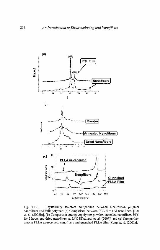
214 An Introduction to Electrospinning and Nanofibers
Fig. 5.19. Crystallinity structure comparison between electrospun polymernanofibers and bulk polymer: (a) Comparison between PCL film and nanofibers [Leeet. al. (2003b)], (b) Comparison among copolymer powder, annealed nanofibers 50°Cfor 2 hours and dried nanofibers at 23°C [Bhattarai et. al. (2003)] and (c) Comparisonamong PLLA as-received, nanofibers and quenched PLLA film [Zong et. al. (2002)].
Chapter 5 Characterization 215
In the case of [Bhattarai et. al. (2003)] (Fig. 5.19(b)), XRDcharacterization was conducted on copolymer powder(PPDO:PLLA:PEG = 20:70:10) and electrospun copolymer nanofibers.An XRD curve of copolymer powder revealed the characteristiccrystalline peaks at 20 = 16.4 and 18.7° corresponding to the PLLAsegments whereas the other segments of the copolymer (i.e., PPDO andPEG) were not indicated because of the lower material ratio. However,the sharp diffraction peaks seen in copolymer powder were not observedin dried nanofibers. It is interesting to note that the annealed nanofibersat 50°C for 2 hours showed the clearer peak than dried nanofibers. Thisimplies that there are some orders of polymer chains in electrospunnanofibers. As shown in Fig. 5.19(c), the DSC result of [Zong et. al.(2002)] showed that as-received PLLA exhibited 36% crystallinitydegree whereas the electrospun PLLA nanofibers exhibited significantlower value. However, XRD result supported that although the polymerchains are non-crystalline in the nanofibers, they are highly oriented.These three cases summarize that electrospun polymer nanofibers dohave order of polymer chains although their crystallinity is notsignificantly high. During polymer jets are traveling to the fibercollector, the electrical force do affects the polymer chain order onnanofibers. In shown reports, it must be noted that randomly alignednanofibers are collected using rotating drum which implies that the fibercollecting speed is not high. Hence, it can be considered that the order ofpolymer chains could be also affected if higher voltage is applied tomake nanofibers or fiber collecting speed is much faster. Such curiositycan be known from the results shown in Table 5.3 and each case isbriefly introduced as follows.
Fig. 5.20 shows how molecular order of electrospun fibers is affected bythe applied voltage although fiber diameter is in sub-micron meter level[Zhao et. al. (2004)]. Ethyl-cyanoethyl cellulose (E-CE)C fibers wereelectrospun on the plate collector with certain distance and then theapplied voltage was varied. The crystallinity of electrospun ethyl-cyanoethyl cellulose (E-CE)C fibers increased with increasing thevoltage.
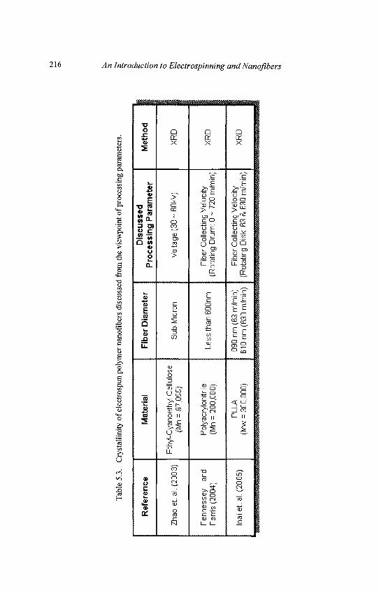
Tab
le 5
.3.
Cry
stal
linity
of
elec
trosp
un p
olym
er n
anof
iber
s di
scus
sed
from
the
view
poin
t of p
roce
ssin
g pa
ram
eter
s.
Ref
eren
ce
Zhao
et.
al.
(200
3)
Et h
yl "(
r en
ne
sse
y an
d F
r ar r
is (
2004
)
Mat
eria
l
^yan
oeth
yl C
ellu
lose
(Mn
= 9
7,00
0)
^oly
acry
loni
trile
(Mn
= 2
00,0
00)
PLL
AM
w=
300
,000
)
Fib
er D
iam
eter
,
Sub
-Mic
ron
Less
tha
n 60
0nm
, D
090
nm (
63 m
/rnin
)31
0 nm
(63
0m/m
in)
(RoP
roce
ssin
g P
aram
eter
Vol
tage
(30
~6
0kV
)
r ibe
r C
olle
ctin
g V
eloc
ityta
ting
Dru
m:
0 ~
720
m/rn
in)
Fib
er C
olle
ctin
g V
eloc
ityta
ting
Dis
k: 6
3 &
B30
m/m
in)
Met
hod
XR
D
XR
D
VD
n
216 An Introduction to Electrospinning and Nanofibers
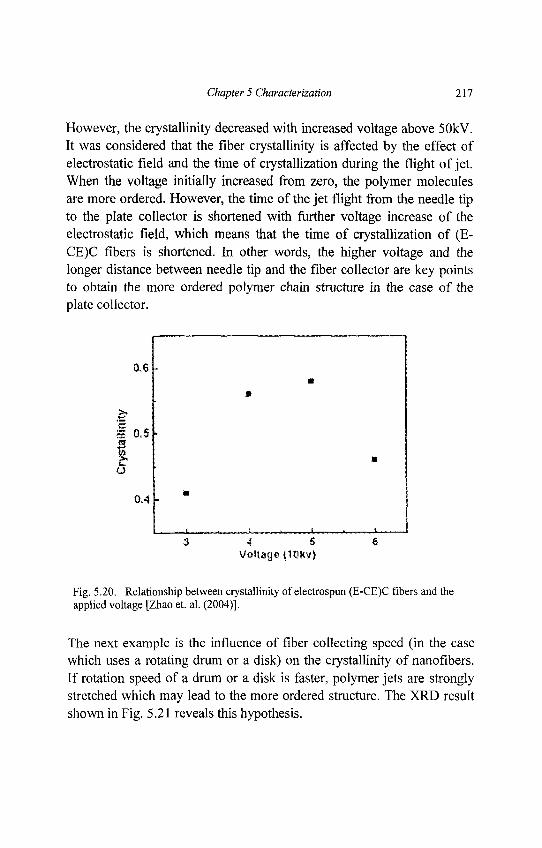
Chapter 5 Characterization 217
However, the crystallinity decreased with increased voltage above 50kV.It was considered that the fiber crystallinity is affected by the effect ofelectrostatic field and the time of crystallization during the flight of jet.When the voltage initially increased from zero, the polymer moleculesare more ordered. However, the time of the jet flight from the needle tipto the plate collector is shortened with further voltage increase of theelectrostatic field, which means that the time of crystallization of (E-CE)C fibers is shortened. In other words, the higher voltage and thelonger distance between needle tip and the fiber collector are key pointsto obtain the more ordered polymer chain structure in the case of theplate collector.
Fig. 5.20. Relationship between crystallinity of electrospun (E-CE)C fibers and theapplied voltage [Zhao et. al. (2004)].
The next example is the influence of fiber collecting speed (in the casewhich uses a rotating drum or a disk) on the crystallinity of nanofibers.If rotation speed of a drum or a disk is faster, polymer jets are stronglystretched which may lead to the more ordered structure. The XRD resultshown in Fig. 5.21 reveals this hypothesis.
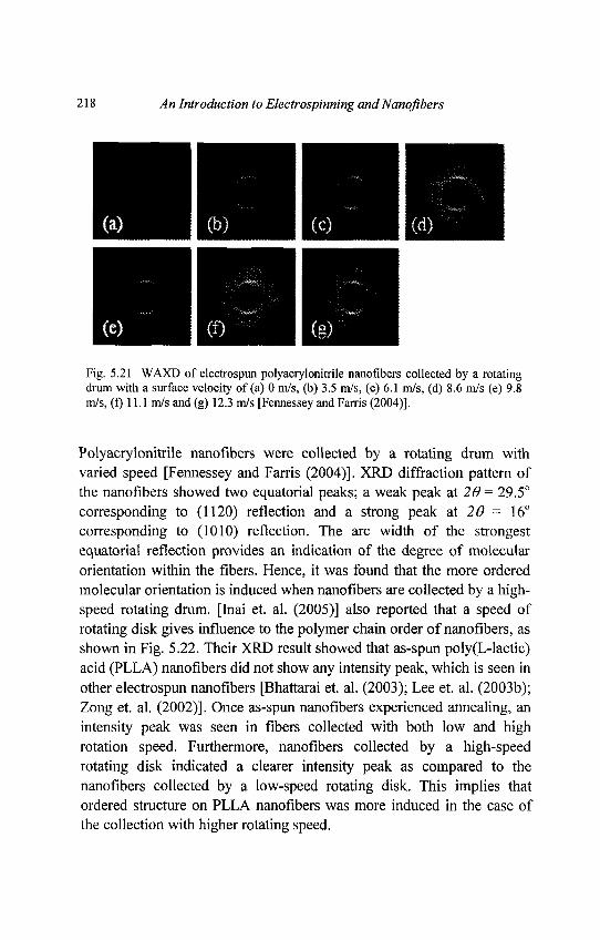
218 An Introduction to Electrospinning and Nanofibers
Fig. 5.21 WAXD of electrospun polyacrylonitrile nanofibers collected by a rotatingdrum with a surface velocity of (a) 0 m/s, (b) 3.5 m/s, (c) 6.1 m/s, (d) 8.6 m/s (e) 9.8m/s, (f) 11.1 m/s and (g) 12.3 m/s [Fennessey and Farris (2004)].
Polyacrylonitrile nanofibers were collected by a rotating drum withvaried speed [Fennessey and Farris (2004)]. XRD diffraction pattern ofthe nanofibers showed two equatorial peaks; a weak peak at 20 = 29.5°corresponding to (1120) reflection and a strong peak at 26 = 16°corresponding to (1010) reflection. The arc width of the strongestequatorial reflection provides an indication of the degree of molecularorientation within the fibers. Hence, it was found that the more orderedmolecular orientation is induced when nanofibers are collected by a high-speed rotating drum. [Inai et. al. (2005)] also reported that a speed ofrotating disk gives influence to the polymer chain order of nanofibers, asshown in Fig. 5.22. Their XRD result showed that as-spun poly(L-lactic)acid (PLLA) nanofibers did not show any intensity peak, which is seen inother electrospun nanofibers [Bhattarai et. al. (2003); Lee et. al. (2003b);Zong et. al. (2002)]. Once as-spun nanofibers experienced annealing, anintensity peak was seen in fibers collected with both low and highrotation speed. Furthermore, nanofibers collected by a high-speedrotating disk indicated a clearer intensity peak as compared to thenanofibers collected by a low-speed rotating disk. This implies thatordered structure on PLLA nanofibers was more induced in the case ofthe collection with higher rotating speed.
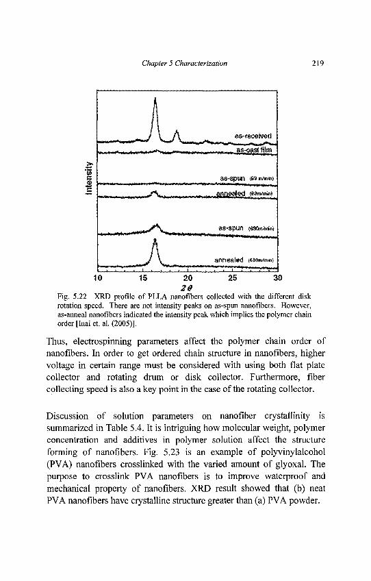
Chapter 5 Characterization 219
Fig. 5.22 XRD profile of PLLA nanofibers collected with the different diskrotation speed. There are not intensity peaks on as-spun nanofibers. However,as-anneal nanofibers indicated the intensity peak which implies the polymer chainorder [Inai et. al. (2005)].
Thus, electrospinning parameters affect the polymer chain order ofnanofibers. In order to get ordered chain structure in nanofibers, highervoltage in certain range must be considered with using both flat platecollector and rotating drum or disk collector. Furthermore, fibercollecting speed is also a key point in the case of the rotating collector.
Discussion of solution parameters on nanofiber crystallinity issummarized in Table 5.4. It is intriguing how molecular weight, polymerconcentration and additives in polymer solution affect the structureforming of nanofibers. Fig. 5.23 is an example of polyvinylalcohol(PVA) nanofibers crosslinked with the varied amount of glyoxal. Thepurpose to crosslink PVA nanofibers is to improve waterproof andmechanical property of nanofibers. XRD result showed that (b) neatPVA nanofibers have crystalline structure greater than (a) PVA powder.
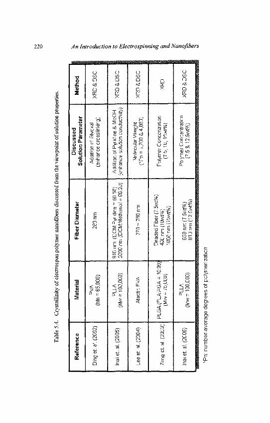
Tab
le 5
.4.
Cry
stal
lini
ty o
f el
ectr
ospu
n po
lym
er n
anof
iber
s di
scus
sed
from
the
view
poin
t of
sol
utio
n pr
oper
ties
.
Ref
eren
ce
Din
g et
. al.
(200
2)
Inai
et.
al. (
2005
)
Lee
et. a
l. (2
004)
Zong
et.
al. (
2003
)
Inai
et.
al. (
2005
)
Mat
eria
l
PV
A(M
n =
65,
000)
PLL
A(M
w=
100
,000
)
Ata
ctic
PVA
PLG
A (
PLA
.PG
A =
10:
90)
(Mw
= 7
5,00
0)
PLL
A(M
w=
100
,000
)
Fib
er D
iam
eter
280
nm
810
nrn
(DC
IVr.P
yrid
ine
= 5
0:50
)20
00 n
rn (
DC
M:M
etha
nol =
80:
20)
27
0- 2
80
nm
Bea
ded
Fibe
r (7
.5w
t%)
400
nm (
10w
t%)
1000
nm(1
5wt%
)
630
nm (7
.5w
t%)
810n
m(1
2.5w
t%)
Dis
cuss
edS
olu
tio
n P
aram
eter
Add
ition
of G
lyox
al(e
nhan
ce c
ross
linki
ng)
Add
ition
of P
yrid
ine
& M
eOH
(enh
ance
sol
utio
n co
nduc
tivity
)
Mol
ecul
ar W
eigh
t(*
Pn=
1,7
00 &
4,00
0)
Pol
ymer
Con
cent
ratio
n(7
.5,
10, 1
5wt%
)
Pol
ymer
Con
cent
ratio
n(7
.5&
12.5
wt%
)
Met
ho
d
XR
D &
DS
C
XR
D&
DS
C
XR
D &
DS
C
XR
D
XR
D &
DS
C
*Pn:
num
ber-
aver
age
degr
ees
of p
olym
eriz
atio
n
220 An Introduction to Electrospinning and Nanojibers
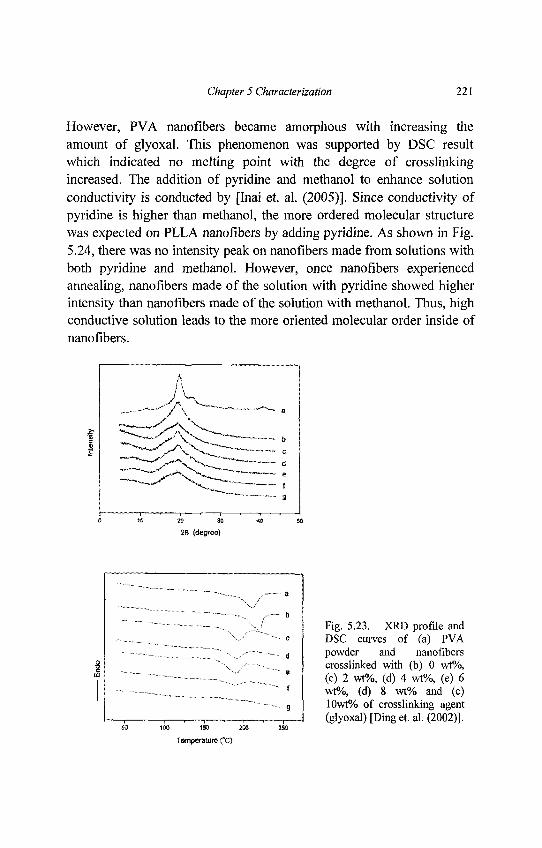
Chapter 5 Characterization 221
However, PVA nanofibers became amorphous with increasing theamount of glyoxal. This phenomenon was supported by DSC resultwhich indicated no melting point with the degree of crosslinkingincreased. The addition of pyridine and methanol to enhance solutionconductivity is conducted by [Inai et. al. (2005)]. Since conductivity ofpyridine is higher than methanol, the more ordered molecular structurewas expected on PLLA nanofibers by adding pyridine. As shown in Fig.5.24, there was no intensity peak on nanofibers made from solutions withboth pyridine and methanol. However, once nanofibers experiencedannealing, nanofibers made of the solution with pyridine showed higherintensity than nanofibers made of the solution with methanol. Thus, highconductive solution leads to the more oriented molecular order inside ofnanofibers.
Fig. 5.23. XRD profile andDSC curves of (a) PVApowder and nanofiberscrosslinked with (b) 0 wt%,(c) 2 wt%, (d) 4 wt%, (e) 6wt%, (d) 8 wt% and (e)10wt% of crosslinking agent(glyoxal) [Ding et. al. (2002)].
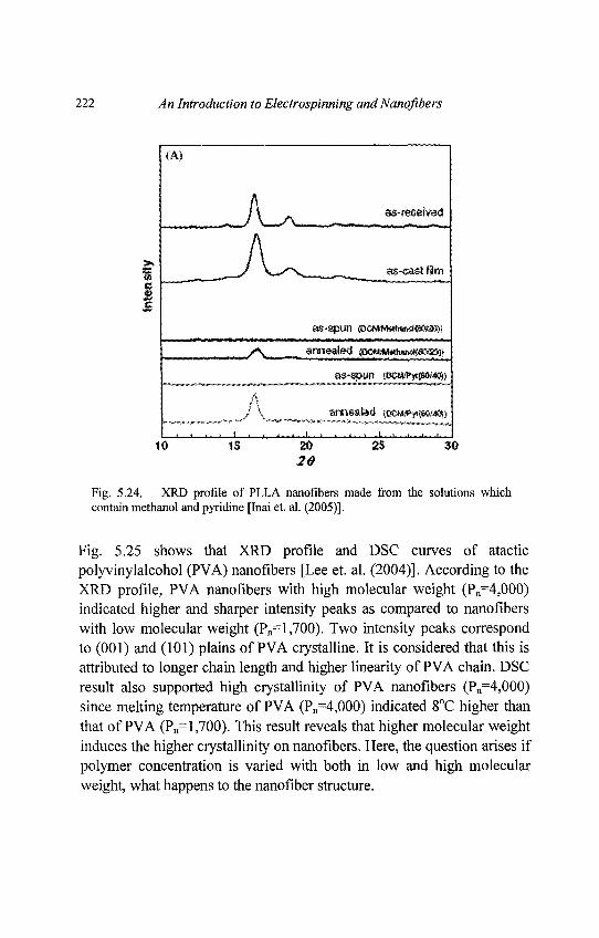
222 An Introduction to Electrospinning and Nanofibers
Fig. 5.24. XRD profile of PLLA nanofibers made from the solutions whichcontain methanol and pyridine [Inai et. al. (2005)].
Fig. 5.25 shows that XRD profile and DSC curves of atacticpolyvinylalcohol (PVA) nanofibers [Lee et. al. (2004)]. According to theXRD profile, PVA nanofibers with high molecular weight (Pn=4,000)indicated higher and sharper intensity peaks as compared to nanofiberswith low molecular weight (Pn=l,700). Two intensity peaks correspondto (001) and (101) plains of PVA crystalline. It is considered that this isattributed to longer chain length and higher linearity of PVA chain. DSCresult also supported high crystallinity of PVA nanofibers (Pn=4,000)since melting temperature of PVA (Pn=4,000) indicated 8°C higher thanthat of PVA (Pn= 1,700). This result reveals that higher molecular weightinduces the higher crystallinity on nanofibers. Here, the question arises ifpolymer concentration is varied with both in low and high molecularweight, what happens to the nanofiber structure.
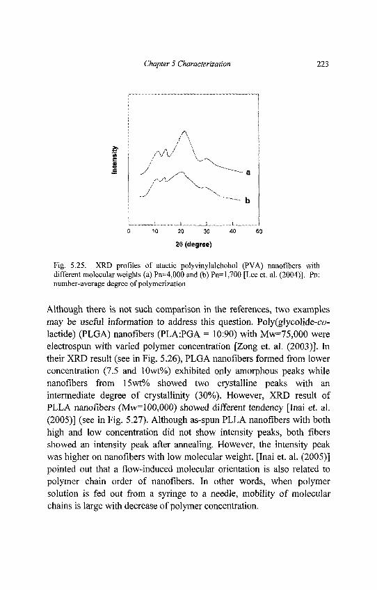
Chapter 5 Characterization ll'i
Fig. 5.25. XRD profiles of atactic polyvinylalchohol (PVA) nanofibers withdifferent molecular weights (a) Pn=4,000 and (b) Pn=l,700 [Lee et. al. (2004)]. Pn:number-average degree of polymerization
Although there is not such comparison in the references, two examplesmay be useful information to address this question. Poly(glycolide-co-lactide) (PLGA) nanofibers (PLA:PGA = 10:90) with Mw=75,000 wereelectrospun with varied polymer concentration [Zong et. al. (2003)]. Intheir XRD result (see in Fig. 5.26), PLGA nanofibers formed from lowerconcentration (7.5 and 10wt%) exhibited only amorphous peaks whilenanofibers from 15wt% showed two crystalline peaks with anintermediate degree of crystallinity (30%). However, XRD result ofPLLA nanofibers (Mw=l00,000) showed different tendency [Inai et. al.(2005)] (see in Fig. 5.27). Although as-spun PLLA nanofibers with bothhigh and low concentration did not show intensity peaks, both fibersshowed an intensity peak after annealing. However, the intensity peakwas higher on nanofibers with low molecular weight. [Inai et. al. (2005)]pointed out that a flow-induced molecular orientation is also related topolymer chain order of nanofibers. In other words, when polymersolution is fed out from a syringe to a needle, mobility of molecularchains is large with decrease of polymer concentration.
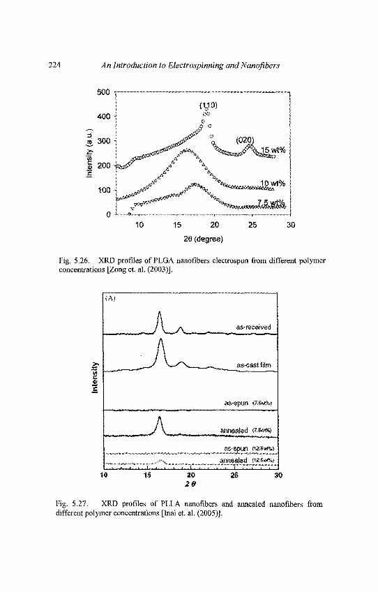
224 An Introduction to Electrospinning and Nanofibers
Fig. 5.26. XRD profiles of PLGA nanofibers electrospun from different polymerconcentrations [Zong et. al. (2003)].
Fig. 5.27. XRD profiles of PLLA nanofibers and annealed nanofibers fromdifferent polymer concentrations [Inai et. al. (2005)].
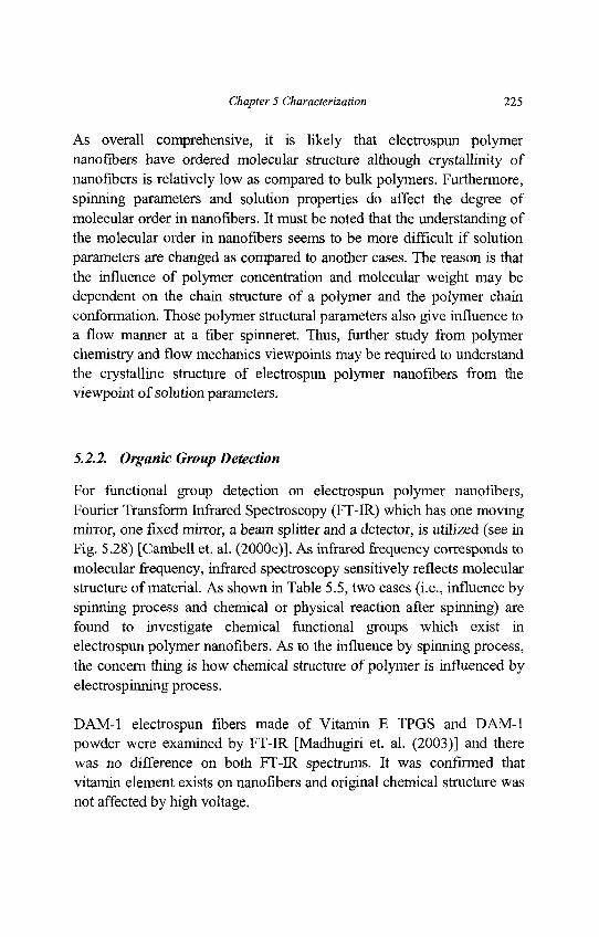
Chapter 5 Characterization 225
As overall comprehensive, it is likely that electrospun polymernanofibers have ordered molecular structure although crystallinity ofnanofibers is relatively low as compared to bulk polymers. Furthermore,spinning parameters and solution properties do affect the degree ofmolecular order in nanofibers. It must be noted that the understanding ofthe molecular order in nanofibers seems to be more difficult if solutionparameters are changed as compared to another cases. The reason is thatthe influence of polymer concentration and molecular weight may bedependent on the chain structure of a polymer and the polymer chainconformation. Those polymer structural parameters also give influence toa flow manner at a fiber spinneret. Thus, further study from polymerchemistry and flow mechanics viewpoints may be required to understandthe crystalline structure of electrospun polymer nanofibers from theviewpoint of solution parameters.
5.2.2. Organic Group Detection
For functional group detection on electrospun polymer nanofibers,Fourier Transform Infrared Spectroscopy (FT-IR) which has one movingmirror, one fixed mirror, a beam splitter and a detector, is utilized (see inFig. 5.28) [Cambell et. al. (2000c)]. As infrared frequency corresponds tomolecular frequency, infrared spectroscopy sensitively reflects molecularstructure of material. As shown in Table 5.5, two cases (i.e., influence byspinning process and chemical or physical reaction after spinning) arefound to investigate chemical functional groups which exist inelectrospun polymer nanofibers. As to the influence by spinning process,the concern thing is how chemical structure of polymer is influenced byelectrospinning process.
DAM-1 electrospun fibers made of Vitamin E TPGS and DAM-1powder were examined by FT-IR [Madhugiri et. al. (2003)] and therewas no difference on both FT-IR spectrums. It was confirmed thatvitamin element exists on nanofibers and original chemical structure wasnot affected by high voltage.
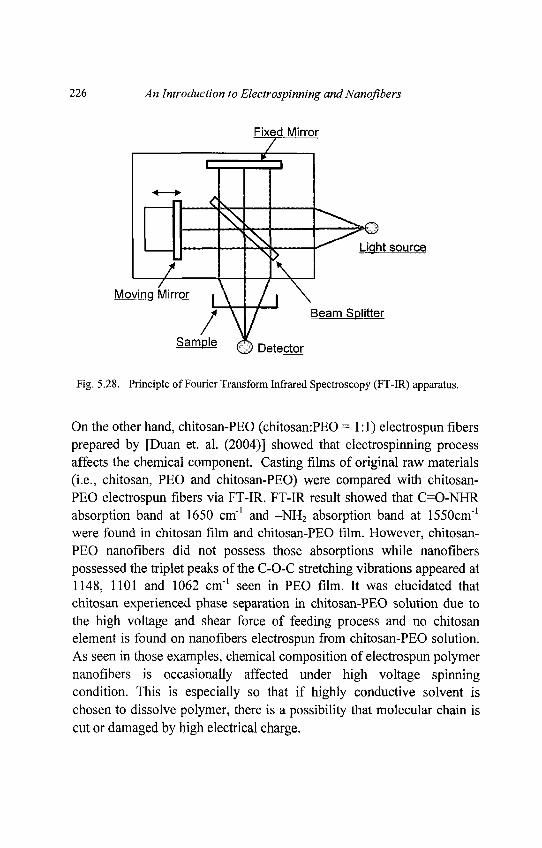
226 An Introduction to Electrospinning and Nanofibers
Fig. 5.28. Principle of Fourier Transform Infrared Spectroscopy (FT-IR) apparatus.
On the other hand, chitosan-PEO (chitosan:PEO =1:1) electrospun fibersprepared by [Duan et. al. (2004)] showed that electrospinning processaffects the chemical component. Casting films of original raw materials(i.e., chitosan, PEO and chitosan-PEO) were compared with chitosan-PEO electrospun fibers via FT-IR. FT-IR result showed that C=O-NHRabsorption band at 1650 cm"1 and -NH2 absorption band at 1550cm"1
were found in chitosan film and chitosan-PEO film. However, chitosan-PEO nanofibers did not possess those absorptions while nanofiberspossessed the triplet peaks of the C-O-C stretching vibrations appeared at1148, 1101 and 1062 cm'1 seen in PEO film. It was elucidated thatchitosan experienced phase separation in chitosan-PEO solution due tothe high voltage and shear force of feeding process and no chitosanelement is found on nanofibers electrospun from chitosan-PEO solution.As seen in those examples, chemical composition of electrospun polymernanofibers is occasionally affected under high voltage spinningcondition. This is especially so that if highly conductive solvent ischosen to dissolve polymer, there is a possibility that molecular chain iscut or damaged by high electrical charge.
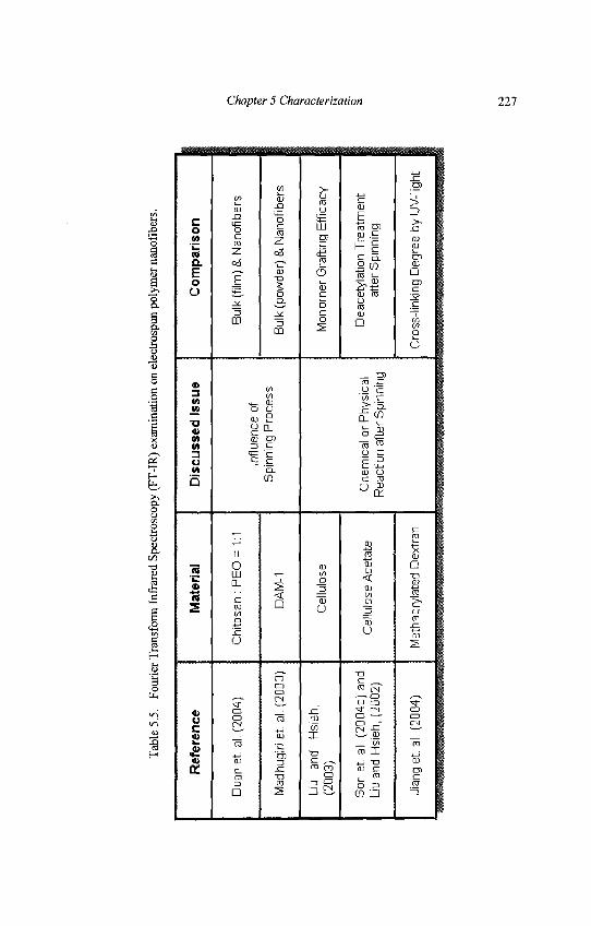
Tab
le 5
.5.
Fou
rier
Tra
nsfo
rm I
nfra
red
Spe
ctro
scop
y (F
T-I
R)
exam
inat
ion
on e
lect
rosp
un p
olym
er n
anof
iber
s.
Ref
eren
ce
Du
an
et.
al.
(20
04
)
Mad
hugi
ri e
t. a
l. (2
003)
Liu
and
H
sieh
,(2
003)
Son
et. a
l. (2
00
4c)
an
dLi
u an
d H
sieh
, (2
002)
Jian
g e
t. a
l. (2
004)
Mat
eria
l
Ch
ito
san
: P
EO
= 1
:1
DA
M-1
Cel
lulo
se
Cel
lulo
se A
ceta
te
Met
hacr
ylat
ed D
extr
an
Dis
cuss
ed I
ssue
Influ
ence
of
Spi
nnin
g P
roce
ss
Ch
em
ica
l or
Phy
sica
lR
eact
ion
afte
r S
pinn
ing
Com
paris
on
Bul
k (f
ilm)
& N
anof
iber
s
Bul
k (p
owde
r) &
Nan
ofib
ers
Mon
omer
Gra
fting
Eff
icac
y
Dea
cety
latio
n T
rea
tme
nt
afte
r S
pinn
ing
Cro
ss-l
inki
ng D
egre
e b
y U
V-l
ight
Chapter 5 Characterization 227
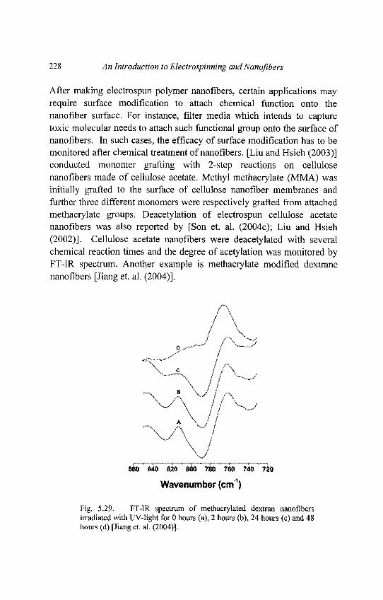
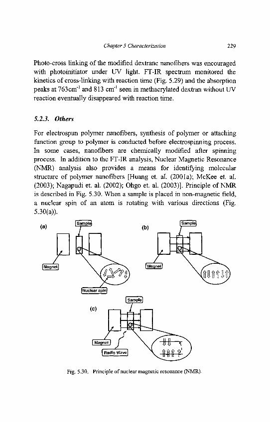
Chapter 5 Characterization 229
Photo-cross linking of the modified dextrane nanofibers was encouragedwith photoinitiator under UV light. FT-IR spectrum monitored thekinetics of cross-linking with reaction time (Fig. 5.29) and the absorptionpeaks at 763cm"1 and 813 cm"1 seen in methacrylated dextran without UVreaction eventually disappeared with reaction time.
5.2.3. Others
For electrospun polymer nanofibers, synthesis of polymer or attachingfunction group to polymer is conducted before electrospinning process.In some cases, nanofibers are chemically modified after spinningprocess. In addition to the FT-IR analysis, Nuclear Magnetic Resonance(NMR) analysis also provides a means for identifying molecularstructure of polymer nanofibers [Huang et. al. (2001a); McKee et. al.(2003); Nagapudi et. al. (2002); Ohgo et. al. (2003)]. Principle of NMRis described in Fig. 5.30. When a sample is placed in non-magnetic field,a nuclear spin of an atom is rotating with various directions (Fig.5.30(a)).
Fig. 5.30. Principle of nuclear magnetic resonance (NMR).
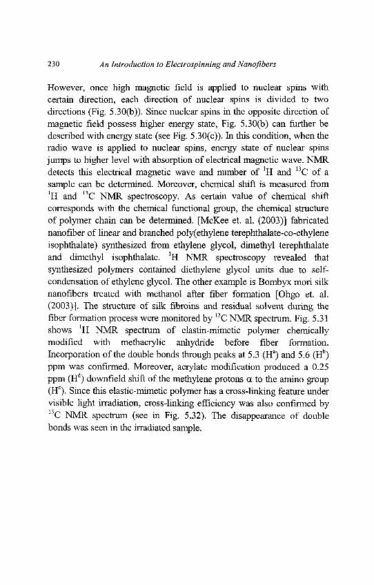
230 An Introduction to Electrospinning andNanofibers
However, once high magnetic field is applied to nuclear spins withcertain direction, each direction of nuclear spins is divided to twodirections (Fig. 5.30(b)). Since nuclear spins in the opposite direction ofmagnetic field possess higher energy state, Fig. 5.30(b) can further bedescribed with energy state (see Fig. 5.30(c)). In this condition, when theradio wave is applied to nuclear spins, energy state of nuclear spinsjumps to higher level with absorption of electrical magnetic wave. NMRdetects this electrical magnetic wave and number of 'H and 13C of asample can be determined. Moreover, chemical shift is measured from'H and 13C NMR spectroscopy. As certain value of chemical shiftcorresponds with the chemical functional group, the chemical structureof polymer chain can be determined. [McKee et. al. (2003)] fabricatednanofiber of linear and branched poly(ethylene terephthalate-co-ethyleneisophthalate) synthesized from ethylene glycol, dimethyl terephthalateand dimethyl isophthalate. 'H NMR spectroscopy revealed thatsynthesized polymers contained diethylene glycol units due to self-condensation of ethylene glycol. The other example is Bombyx mori silknanofibers treated with methanol after fiber formation [Ohgo et. al.(2003)]. The structure of silk fibroins and residual solvent during thefiber formation process were monitored by 13C NMR spectrum. Fig. 5.31shows 'H NMR spectrum of elastin-mimetic polymer chemicallymodified with methacrylic anhydride before fiber formation.Incorporation of the double bonds through peaks at 5.3 (Ha) and 5.6 (Hb)ppm was confirmed. Moreover, acrylate modification produced a 0.25ppm (Hd) downfield shift of the methylene protons a to the amino group(Hc). Since this elastic-mimetic polymer has a cross-linking feature undervisible light irradiation, cross-linking efficiency was also confirmed by13C NMR spectrum (see in Fig. 5.32). The disappearance of doublebonds was seen in the irradiated sample.
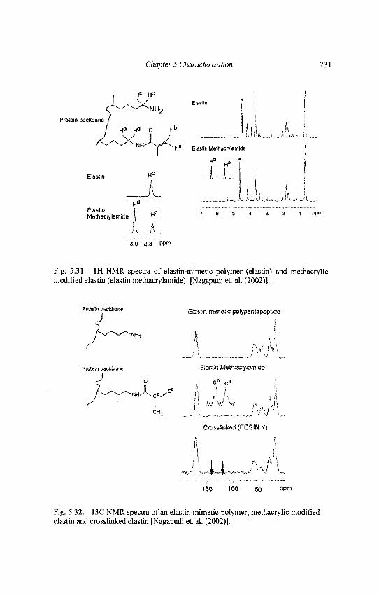
Chapter 5 Characterization 231
Fig. 5.31. 1H NMR spectra of elastin-mimetic polymer (elastin) and methacrylicmodified elastin (elastin methacrylamide) [Nagapudi et. al. (2002)].
Fig. 5.32. 13C NMR spectra of an elastin-mimetic polymer, methacrylic modifiedelastin and crosslinked elastin [Nagapudi et. al. (2002)].
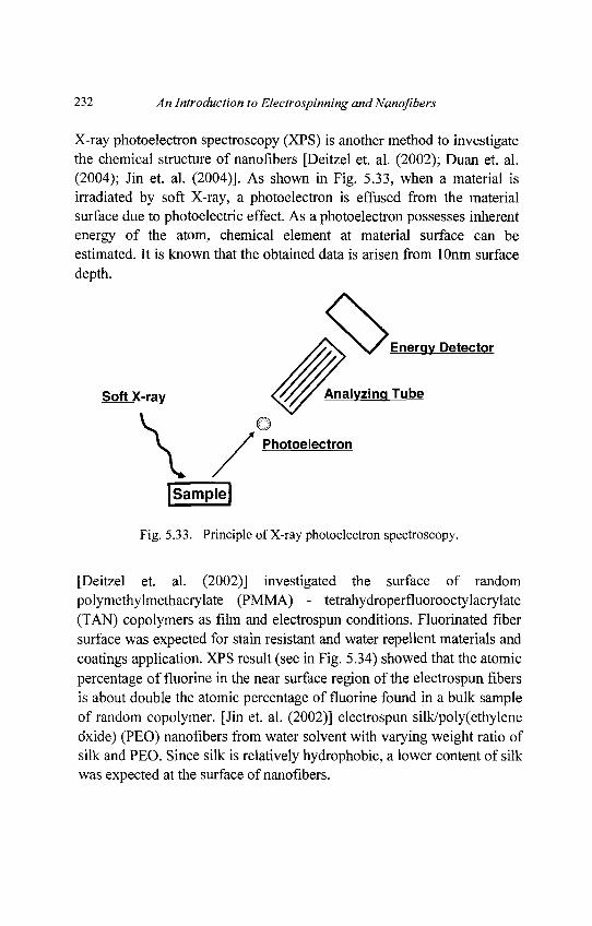
232 An Introduction to Electrospinning and Nanofibers
X-ray photoelectron spectroscopy (XPS) is another method to investigatethe chemical structure of nanofibers [Deitzel et. al. (2002); Duan et. al.(2004); Jin et. al. (2004)]. As shown in Fig. 5.33, when a material isirradiated by soft X-ray, a photoelectron is effused from the materialsurface due to photoelectric effect. As a photoelectron possesses inherentenergy of the atom, chemical element at material surface can beestimated. It is known that the obtained data is arisen from lOnm surfacedepth.
Fig. 5.33. Principle of X-ray photoelectron spectroscopy.
[Deitzel et. al. (2002)] investigated the surface of randompolymethylmethacrylate (PMMA) - tetrahydroperfluorooctylacrylate(TAN) copolymers as film and electrospun conditions. Fluorinated fibersurface was expected for stain resistant and water repellent materials andcoatings application. XPS result (see in Fig. 5.34) showed that the atomicpercentage of fluorine in the near surface region of the electrospun fibersis about double the atomic percentage of fluorine found in a bulk sampleof random copolymer. [Jin et. al. (2002)] electrospun silk/poly(ethyleneoxide) (PEO) nanofibers from water solvent with varying weight ratio ofsilk and PEO. Since silk is relatively hydrophobic, a lower content of silkwas expected at the surface of nanofibers.
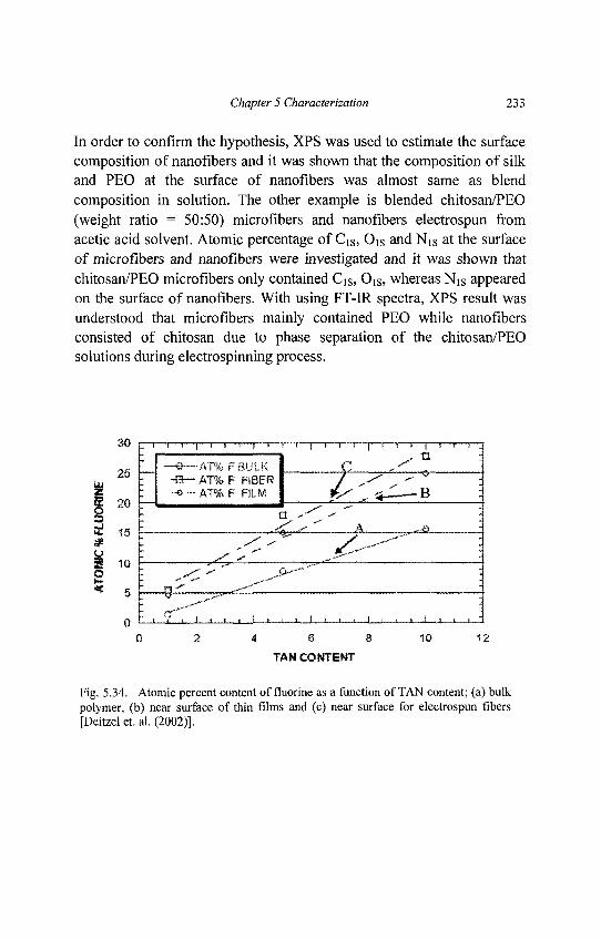
Chapter 5 Characterization 233
In order to confirm the hypothesis, XPS was used to estimate the surfacecomposition of nanofibers and it was shown that the composition of silkand PEO at the surface of nanofibers was almost same as blendcomposition in solution. The other example is blended chitosan/PEO(weight ratio = 50:50) microfibers and nanofibers electrospun fromacetic acid solvent. Atomic percentage of CiS, Ois and NiS at the surfaceof microfibers and nanofibers were investigated and it was shown thatchitosan/PEO microfibers only contained Cis, OiS, whereas NiS appearedon the surface of nanofibers. With using FT-IR spectra, XPS result wasunderstood that microfibers mainly contained PEO while nanofibersconsisted of chitosan due to phase separation of the chitosan/PEOsolutions during electrospinning process.
Fig. 5.34. Atomic percent content of fluorine as a function of TAN content; (a) bulkpolymer, (b) near surface of thin films and (c) near surface for electrospun fibers[Deitzel et. al. (2002)].
234 An Introduction to Electrospinning and Nanofibers
5.3. Mechanical Property
Electrospun polymer nanofibers have several possible applications suchas filtration, tissue scaffolds, protective clothing, gas sensors etc. In orderto meet with long-life durability in those applications, mechanicalproperties of nanofibrous membrane as well as a single nanofiber has tobe discussed. From the material science view point, the size effect onsingle fiber property should be an interesting topic. There arise somequestions on what happens to the mechanical properties of a single fiberwhen the fiber diameter shrinks from micron to nano size level. Inaddition, a question is raised on how fiber diameter shrinks to nano levelduring fiber processing since crystalline structure of a single fiber isaffected by processing condition even in a same diameter of two types offibers. In terms of the mechanical testing of nanofibrous membranes,traditional tensile testing method is applied. However, the testing ofsingle nanofiber needs much know-how since it is not an easy task toprepare the sample and to apply the loading to a tiny nanofiber. Hence,single fiber testing is limited as compared to nanofibrous membranetesting. In this section, methodologies of mechanical testing onelectrbspun polymer nanofibers have been introduced and their validityhas been discussed.
5.3.1. Single Nanofiber
As summarized in Table 5.6, there are few number of scientific papersdiscussed about the mechanical property of electrospun singlenanofibers. The reasons should be the handling difficulty to extract asingle fiber from the electrospun nanofiber web and also non-availabilityof accurate testing apparatus. In the literatures, three testing apparatus areavailable to measure tensile and bending properties of a single nanofiber,i.e., 1.Cantilever technique [Buer et. al. (2001)], 2.AFM-basednanoindentation system [Tan and Lim (2004)] and 3.Nano tensile tester[Tan et. al. (2005); Inai et. al. (2005)]. Schematic methodology ofcantilever technique is described in Fig. 5.35 [Buer et. al. (2001)].
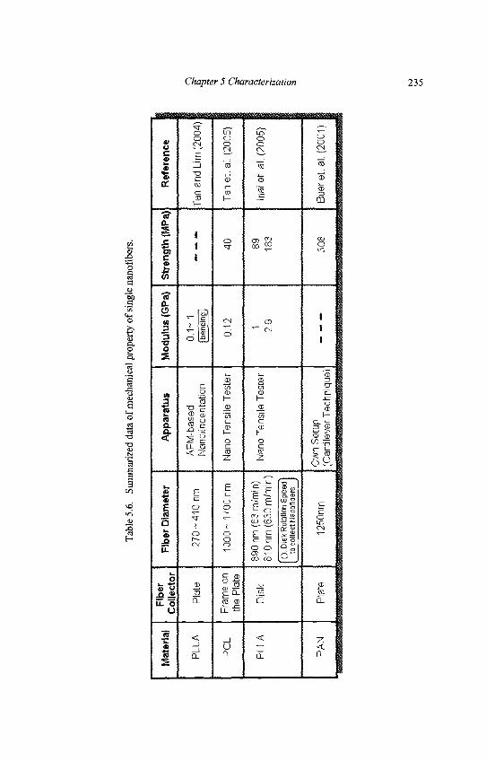
Tab
le 5
.6.
Sum
mar
ized
dat
a of
mec
hani
cal
prop
erty
of
sing
le n
anof
iber
s.
Mat
eria
l
PLL
A
PC
L
PLL
A
PA
N
Fibe
rC
olle
cto
r
Pla
te
Fra
me
onth
e P
late
Dis
k
Pla
te
Fib
er D
iam
eter
27
0- 4
10
nm
10
00
- 17
00
nm
890
nm (
63
rn/m
in)
610
nm (
630m
/tni
n)
( ):
Dis
k R
otat
ion
Spe
edto
col
lect
Nan
ofib
ers
1250
nm
Ap
par
atu
s
AF
M-b
ased
Nan
oiin
dent
atio
n
Nan
o T
ensi
le T
este
r
Nan
o T
ensi
le T
este
r
Ow
n S
etup
(Can
tilev
er T
echn
ique
)
Mo
du
lus
(GP
a)
0.1
- 1[b
endi
ng ]
0.12 1 2.9
Str
eng
th (
MP
a)
- -
-
40 89 183
308
Ref
eren
ce
Tan
and
Lim
(20
04)
Tan
et.
al.
(200
5)
Inai
et.
al.
(200
5)
Bu
ere
t. a
l. (2
001)
i Chapte rSCha 1 *
i a
ttion 1
Chapter 5 Characterization 235
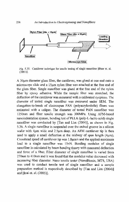
236 An Introduction to Electrospinning and Nanofibers
Fig. 5.35. Cantilever technique for tensile testing of single nanofiber [Buer et. al.(2001)].
A 30nm diameter glass fiber, the cantilever, was glued at one end onto amicroscope slide and a 15um nylon fiber was attached at the free end ofthe glass fiber. Single nanofiber was glued at the free end of the nylonfiber by epoxy adhesive. While the sample fiber was stretched, thedeflection of the cantilever was measured with a calibrated eyepiece. Thediameter of tested single nanofiber was measured under SEM. Theelongation-to-break of electrospun PAN (polyacrylonitrile) fibers wasestimated with a caliper. The diameter of tested PAN nanofiber was1250nm and fiber tensile strength was 300MPa. Using AFM-basednanoindentation system, bending test of PLLA (poly-L-lactic-acid) singlenanofiber was conducted by [Tan and Lim (2004)], as shown in Fig.5.36. A single nanofiber is suspended over the etched groove in a siliconwafer with 4um wide and 2.5um deep. An AFM cantilever tip is thenused to apply a small deflection at the midway of span length (4um).Crosshead speed of cantilever tip was 1.8um/s and the applied maximumload to a single nanofiber was 15nN. Bending modulus of singlenanofiber is calculated by beam bending theory with measured deflectionand force of a fiber. Fiber diameter of single nanofiber is varied from270nm to 410nm and it was found that the modulus value decreased withincreasing fiber diameter. Nano tensile tester (NanoBionix, MTS, USA)was used to conduct tensile test of single nanofiber and a samplepreparation method is respectively described by [Tan and Lim (2004)]and [Inai et. al. (2005)].
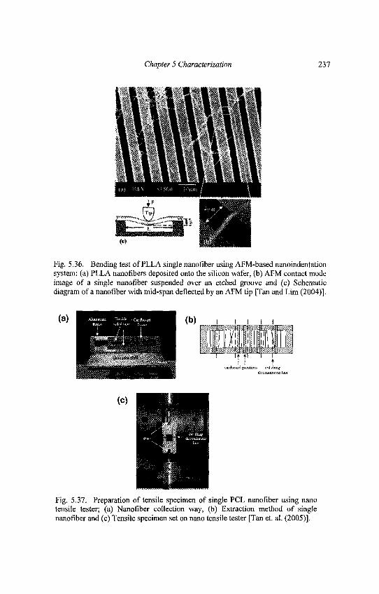
Chapter 5 Characterization 237
Fig. 5.36. Bending test of PLLA single nanofiber using AFM-based nanoindentationsystem: (a) PLLA nanofibers deposited onto the silicon wafer, (b) AFM contact modeimage of a single nanofiber suspended over an etched groove and (c) Schematicdiagram of a nanofiber with mid-span deflected by an AFM tip [Tan and Lim (2004)].
Fig. 5.37. Preparation of tensile specimen of single PCL nanofiber using nanotensile tester; (a) Nanofiber collection way, (b) Extraction method of singlenanofiber and (c) Tensile specimen set on nano tensile tester [Tan et. al. (2005)].
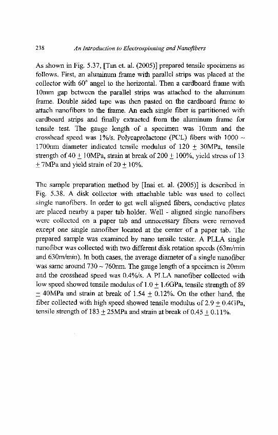
238 An Introduction to Electrospinning and Nanofibers
As shown in Fig. 5.37, [Tan et. al. (2005)] prepared tensile specimens asfollows. First, an aluminum frame with parallel strips was placed at thecollector with 60° angel to the horizontal. Then a cardboard frame with10mm gap between the parallel strips was attached to the aluminumframe. Double sided tape was then pasted on the cardboard frame toattach nanofibers to the frame. An each single fiber is partitioned withcardboard strips and finally extracted from the aluminum frame fortensile test. The gauge length of a specimen was 10mm and thecrosshead speed was 1%/s. Polycaprolactone (PCL) fibers with 1000 ~1700nm diameter indicated tensile modulus of 120 + 30MPa, tensilestrength of 40 + lOMPa, strain at break of 200 + 100%, yield stress of 13± 7MPa and yield strain of 20 ± 10%.
The sample preparation method by [Inai et. al. (2005)] is described inFig. 5.38. A disk collector with attachable table was used to collectsingle nanofibers. In order to get well aligned fibers, conductive platesare placed nearby a paper tab holder. Well - aligned single nanofiberswere collected on a paper tab and unnecessary fibers were removedexcept one single nanofiber located at the center of a paper tab. Theprepared sample was examined by nano tensile tester. A PLLA singlenanofiber was collected with two different disk rotation speeds (63m/minand 630m/min). In both cases, the average diameter of a single nanofiberwas same around 730 ~ 760nm. The gauge length of a specimen is 20mmand the crosshead speed was 0.4%/s. A PLLA nanofiber collected withlow speed showed tensile modulus of 1.0 + 1.6GPa, tensile strength of 89+ 40MPa and strain at break of 1.54 + 0.12%. On the other hand, thefiber collected with high speed showed tensile modulus of 2.9 + 0.4GPa,tensile strength of 183 + 25MPa and strain at break of 0.45 + 0.11%.
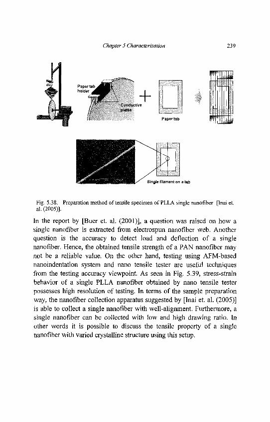
Chapter 5 Characterization 239
Fig. 5.38. Preparation method of tensile specimen of PLLA single nanofiber [Inai et.al. (2005)].
In the report by [Buer et. al. (2001)], a question was raised on how asingle nanofiber is extracted from electrospun nanofiber web. Anotherquestion is the accuracy to detect load and deflection of a singlenanofiber. Hence, the obtained tensile strength of a PAN nanofiber maynot be a reliable value. On the other hand, testing using AFM-basednanoindentation system and nano tensile tester are useful techniquesfrom the testing accuracy viewpoint. As seen in Fig. 5.39, stress-strainbehavior of a single PLLA nanofiber obtained by nano tensile testerpossesses high resolution of testing. In terms of the sample preparationway, the nanofiber collection apparatus suggested by [Inai et. al. (2005)]is able to collect a single nanofiber with well-alignment. Furthermore, asingle nanofiber can be collected with low and high drawing ratio. Inother words it is possible to discuss the tensile property of a singlenanofiber with varied crystalline structure using this setup.
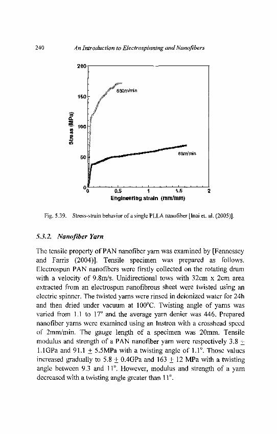
240 An Introduction to Electrospinning andNanofibers
Fig. 5.39. Stress-strain behavior of a single PLLA nanofiber [Inai et. al. (2005)].
5.3.2. Nanofiber Yam
The tensile property of PAN nanofiber yarn was examined by [Fennesseyand Farris (2004)]. Tensile specimen was prepared as follows.Electrospun PAN nanofibers were firstly collected on the rotating drumwith a velocity of 9.8m/s. Unidirectional tows with 32cm x 2cm areaextracted from an electrospun nanofibrous sheet were twisted using anelectric spinner. The twisted yarns were rinsed in deionized water for 24hand then dried under vacuum at 100°C. Twisting angle of yarns wasvaried from 1.1 to 17° and the average yarn denier was 446. Preparednanofiber yarns were examined using an Instron with a crosshead speedof 2mm/min. The gauge length of a specimen was 20mm. Tensilemodulus and strength of a PAN nanofiber yarn were respectively 3.8 +1.1 GPa and 91.1 + 5.5MPa with a twisting angle of 1.1°. Those valuesincreased gradually to 5.8 + 0.4GPa and 163 + 12 MPa with a twistingangle between 9.3 and 11°. However, modulus and strength of a yarndecreased with a twisting angle greater than 11°.
Chapter 5 Characterization 241
Mechanical property of nanofiber yarns is important as well as that ofsingle nanofibers. The reason is the creation of textile fabrics made ofnanofiber yarns which have not been found in recent scientific papers. Inorder to create nano textile fabrics, nanofiber yarns composing textilestructure must be mechanically investigated as nanofiber yarns gothrough textile performing machine. Nano textile fabrics would haveseveral potentials in medical and chemical separation, and chemicalprotection [Scardino and Balonis, 2001; Laurencin and Ko, 2004].Hence, if the potential of nano textile fabrics will be eventuallyrecognized in near future, the discussion about the mechanical propertyof nanofiber yarns would be hot.
5.3.3. Nanofiber Membrane
Tensile properties of electrospun polymer nanofibrous membranes in theliteratures are summarized in Table 5.7. For specimen preparation,dumbbell and rectangular shapes are available, as shown in Fig. 5.40.Although rectangular shape specimen is easily prepared, the question isstress concentration vicinity grip part. Hence, there is the possibility toget the exaggerated testing value. On the other hand, dumbbell shapespecimen precisely removes the stress concentration and the obtainedtesting values are cross to true properties. However, preparation ofdumbbell shape specimen of nanofiber membranes is costly since sharpdumbbell shape blade must be used. Used tensile apparatus isconventional universal testing machine and testing speed is lOmm/min in6 cases [Bhattarai et. al. (2003); Lee et. al. (2003b); Wnek et. al. (2003);Lee et. al. (2002a); Khil et. al. (2004); Huang et. al. (2004)]. Testingspeed depends on testing purpose, for instance, slow testing speed issuitable to observe membrane deformation manner. As seen in Table 5.7,there are two different fiber collecting ways on discussion of tensileproperties of nanofiber membranes.
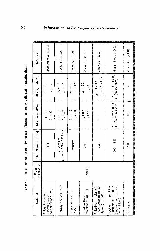
Tab
le 5
.7.
Ten
sile
pro
perti
es o
f po
lym
er n
ano
fibr
ous
mem
bran
es c
olle
cted
by
rota
ting
drum
.
Mat
eria
l
Pol
y(p-
diox
anon
e-co
-L-
lact
ide)
-blo
ck-
poly
(eth
ylen
e gl
ycol
)
Pol
ycap
rola
cton
e (P
CL)
Pol
y(vi
nyl
chlo
ride)
(PV
C)
Pol
y(tr
imet
hyle
nete
reph
thal
ate)
(P
TT
)
Pol
yfvi
nyl
alco
hol)
(PV
A)
cros
s-lin
ked
bygl
yoxa
l(0~
10w
t%)
Acr
ylat
e m
odifi
edE
last
omer
ic
Pro
tein
(deg
ree
of
prot
ein
cros
s-lin
king
)
Fib
rinog
en
Fib
erO
rie n
tatio
n
Alig
ned
Fib
er D
iam
eter
(nm
)
380
Not
spe
cifie
d(b
etw
een
200
- 55
00nm
)
Unk
now
n
400
280
30
0-
1500
700
Mod
ulus
(M
Pa)
EL
= 3
0
ET=
30
EL
= 3
.7
ET=
2.7
EL
= 7
.8
ET=
7. 8
EL
= 0
.7
ET=
1. 1
700
(Unc
ross
-link
ed)
1800
(cr
oss-
linke
d)
80
Str
engt
h (M
Pa)
CT
L=
1.2
CT
T=
1
.4
cr L
=
1.4
CT
T=
1
.2
cr
L=
1. 8
£T
T=
1
.7
crL
= 2
.2
crT=
4.1
CT
L =
7- 8
. 5
cr T
=9
.5~
10.5
16 (
Unc
ross
-link
ed)
43 (
cros
s-lin
ked)
2
Ref
eren
ce
Bha
ttara
i et.
al.
(200
3)
Lee
et.a
l. (2
003b
)
Lee
et.
al. (
2002
a)
Khi
l et.
al.
(200
4)
Din
g et
.al.
(200
2)
Nag
apud
i et
. al.
(200
2)
Wne
k et
.al.
(200
3)
242 An Introduction to Electrospinning and Nanofibers
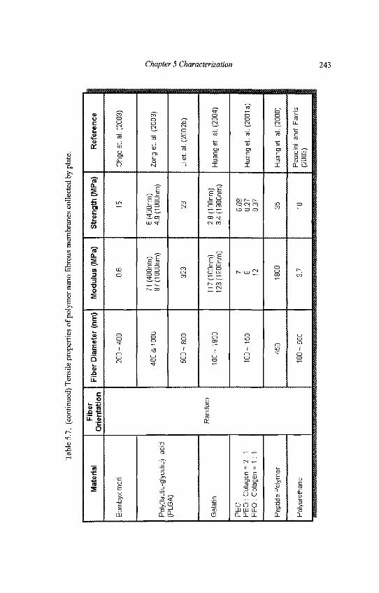
Tab
le 5
.7.
(conti
nued
) T
ensi
le p
roper
ties
of
poly
mer
nan
o f
ibro
us
mem
bra
nes
collec
ted
by
pla
te.
Mate
rial
Bom
byx
mor
i
Pol
y(la
ctic
-gly
colic
) ac
id(P
LGA
)
Gel
atin
PE
OP
EO
: C
olag
en =
2:1
PE
O :
Col
agen
=1
:1
Pep
tide
Pol
ymer
Pol
yure
than
e
Fib
er
Ori
en
tati
on
Ra
nd
om
Fib
er
Dia
mete
r (n
m)
20
0-4
00
400 &
100
0
50
0-8
00
10
0-
1900
10
0-
150
450
10
0-5
00
Mo
du
lus
(M
Pa)
O.B
71 (
400n
m)
87(1
D00
nm)
323
11
7(1
00
nm
)1
23
(19
00
nm
)
7 8 12
1800
37
Str
en
gth
(M
Pa)
15
B (
400n
m)
4.9
(10
00
nm
)
23
2.9
(1 O
Onm
)3
.4( i
a0
0n
m)
0.09
0.27
0.37 35 10
Re
fere
nc
e
Ohg
o et.
al.
(200
3)
Zon
g e
t. a
l. (2
003)
Li e
t. a
l. (2
002b
)
Hua
ng e
t. a
l. (2
004)
Hua
ng e
t. a
l. (2
001a
)
Hua
ng e
t. a
l. (2
000)
Ped
icin
i a
nd
Far
ris
(200
3)
Chapter 5 Characterization 243
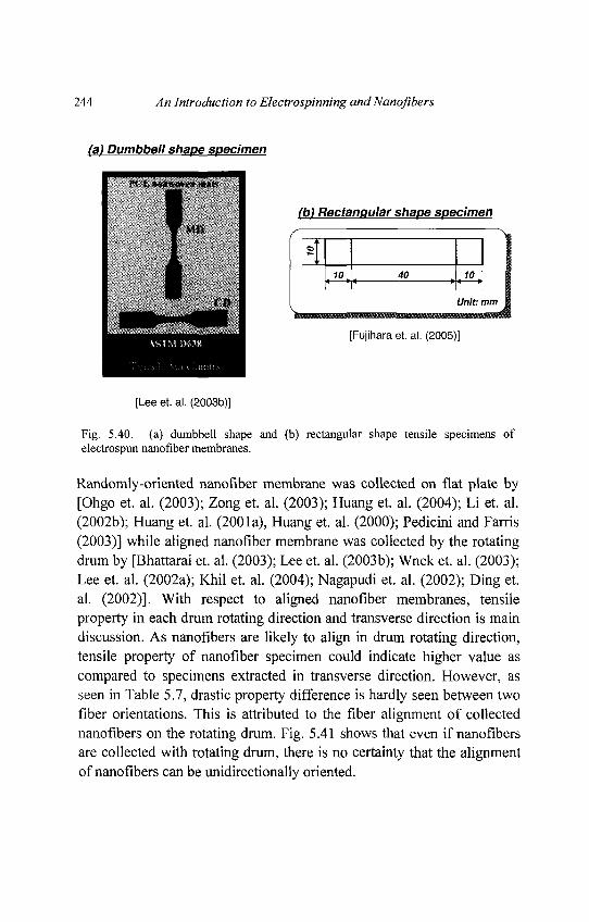
244 An Introduction to Electrospinning and Nanofibers
Fig. 5.40. (a) dumbbell shape and (b) rectangular shape tensile specimens ofelectrospun nanofiber membranes.
Randomly-oriented nanofiber membrane was collected on flat plate by[Ohgo et. al. (2003); Zong et. al. (2003); Huang et. al. (2004); Li et. al.(2002b); Huang et. al. (2001a), Huang et. al. (2000); Pedicini and Farris(2003)] while aligned nanofiber membrane was collected by the rotatingdrum by [Bhattarai et. al. (2003); Lee et. al. (2003b); Wnek et. al. (2003);Lee et. al. (2002a); Khil et. al. (2004); Nagapudi et. al. (2002); Ding et.al. (2002)]. With respect to aligned nanofiber membranes, tensileproperty in each drum rotating direction and transverse direction is maindiscussion. As nanofibers are likely to align in drum rotating direction,tensile property of nanofiber specimen could indicate higher value ascompared to specimens extracted in transverse direction. However, asseen in Table 5.7, drastic property difference is hardly seen between twofiber orientations. This is attributed to the fiber alignment of collectednanofibers on the rotating drum. Fig. 5.41 shows that even if nanofibersare collected with rotating drum, there is no certainty that the alignmentof nanofibers can be unidirectionally oriented.
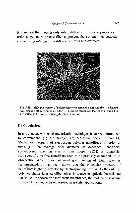
Chapter 5 Characterization 245
It is natural that there is only subtle difference of tensile properties. Inorder to get more precise fiber alignment, the current fiber collectionsystem using rotating drum still needs further improvement.
Fig. 5.41. SEM photograph of poly(trimethylene terephthalate) nanofibers collectedwith rotating drum [Khil et. al. (2004)]. It can be recognized that fiber alignment isnot perfect in MD (drum rotating direction) direction.
5.4 Conclusions
In this chapter, various characterization techniques have been introducedto comprehend (1) Morphology, (2) Molecular Structure and (3)Mechanical Property of electrospun polymer nanofibers. In order toinvestigate the average fiber diameter of deposited nanofibers,conventional scanning electron microscope (SEM) is available.However, if ultra-fine nanofibers need to be precisely examined, TEMobservation which does not need gold coating of 15nm layer isrecommended. It has been shown that the molecular structure ofnanofibers is greatly affected by electrospinning process. As the order ofpolymer chains in a nanofiber gives influence to optical, thermal andmechanical response of nanofibrous membranes, the molecular structureof nanofibers need to be understood in specific applications.
246 An Introduction to Electrospinning andNanofibers
This is also applied to the nanofibers which require chemical surfacetreatment. It has been shown that tensile property of nanofibrousmembranes is easily characterized using the conventional testingmachine. However, careful sample preparation and assessment arerequired to understand the mechanical properties of a single nanofiber.
Chapter 6
Functionalization of Polymer Nanofibers
The extensive research activities on electrospun polymer nanofibers areencouraged by great potential of the nanofibers for many applications(See chapter 8). However, most of polymer nanofibers are chemicallyinert and do not have any specific functions. For the applications to besuccessful the electrospun polymer nanofibers must be functionalized.For example, for the nanofibers to be used as affinity membrane for IgGpurification, protein A or protein G should be covalently bonded onnanofiber surface; for the nanofiber mesh to be used as protective cloth,capture agents need to be immobilized on the nanofiber surface tocapture and decompose toxic molecules. In this chapter, principles ofpolymer surface modification techniques that have been employed ormay be employed in the future to functionalize polymer nanofibers willbe introduced first, followed by examples of polymer nanofiberfunctionalization works which are categorized in terms of differentapplications.
6.1. Polymer Surface Modification
6.1.1. Introduction
Polymer surface modification is an old topic due to the wide applicationof synthetic polymeric materials in human society in such wide fields asadhesion, membrane filtration, coatings, friction and wear, composites,microelectronic devices, thin-film technology and biomaterials, etc.
247
248 An Introduction to Electrospinning and Nanofibers
In general, special surface properties with regard to chemicalcomposition, hydrophilicity, roughness, crystallinity, conductivity,lubricity, and cross-linking density are required for the success of theseapplications. However, polymers very often do not possess the surfaceproperties needed for these applications. In fact, most of themechanically strong and chemically stable polymers usually have inertsurfaces both chemically and biologically. Vice versa, those polymershaving active surfaces usually do not possess excellent mechanicalproperties which are critical for their successful application.
Due to this dilemma, surface modification of the polymers withoutchanging the bulk properties has been an old classical research topic formany years, and is still receiving extensive studies due to more and morenew applications of polymeric materials, especially in the field ofbiotechnology and bioengineering. Common surface modificationtechniques include treatments by blending, coating, radiation withelectromagnetic wave, electron beam, ion beam [Dong and Bell (1999);Brown (2003)] or atom beams[Chan et. al. (1996)], corona or plasmastreatment [Liston et. al. (1993); Grace and Gerenser (2003); Chu et. al.(2002)], chemical vapor deposition (CVD), gas oxidation, metallization,chemical modifications use wet-treatment and surface graftingpolymerization [Uyama et. al. (1998); Kato et. al. (2003)] etc. Progressin recent years has been summarized by several good reviews [Ikada(1994); Ratner (1995); Desai et. al. (2004)].
6.1.2. Physical Coating or Blending
Perhaps the easiest and the most strait forward way to modify polymersurface is by blending functional molecules into the bulk polymer or justcoating it on the polymer surface. Although the biggest limitation of thistechnique is the instability of the polymer surface composition caused bythe lost of the functional materials from the polymer, it is still a goodchoice if this lost is too slow to be considered, or not fast enough toaffect the application of the materials.
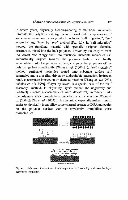
Chapter 6 Functionalization of Polymer Nanofibers 249
In recent years, physically blending/coating of functional moleculesinto/onto the polymers was significantly developed by appearance ofsome new techniques, among which includes "self migration", "selfassembly" and "layer by layer" method (Fig. 6.1). In "self migration"method, the functional material with specially designed chemicalstructure is mixed into the bulk polymer. Driven by tendency to reachthe lowest free energy state, the functional materials molecules canautomatically migrate towards the polymer surface and finallyaccumulated onto the polymer surface, changing the properties of thepolymer surface significantly [Wang et. al. (2000)]. In "self assembly"method, surfactant molecules coated onto substrate surface selfassembled into a thin film, driven by hydrophobic interaction, hydrogenbond, electrostatic interaction or chemical reaction [Zhang et. a/.(1999);Pakalns et. al. (1999)]. "Layer by layer" is a special case of the "selfassembly" method. In "layer by layer" method the negatively andpositively charged macromolecules were alternatively introduced ontothe polymer surface through the strong electrostatic interaction [Wang et.al. (2004c); Zhu et. al. (2003)]. This technique especially makes it mucheasier to physically immobilize some charged protein or DNA moleculeson the polymer surface than to covalently immobilize thesebiomolecules.
Fig. 6.1. Schematic illustrations of self migration, self assembly and layer by layeradsorption techniques.
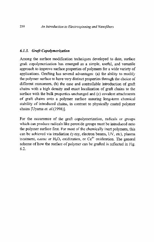
250 An Introduction to Electrospinning and Nanofibers
6.1.3. Graft Copolymerization
Among the surface modification techniques developed to date, surfacegraft copolymerization has emerged as a simple, useful, and versatileapproach to improve surface properties of polymers for a wide variety ofapplications. Grafting has several advantages: (a) the ability to modifythe polymer surface to have very distinct properties through the choice ofdifferent monomers, (b) the ease and controllable introduction of graftchains with a high density and exact localization of graft chains to thesurface with the bulk properties unchanged and (c) covalent attachmentsof graft chains onto a polymer surface assuring long-term chemicalstability of introduced chains, in contrast to physically coated polymerchains [Uyama et. a/.(1998)].
For the occurrence of the graft copolymerization, radicals or groupswhich can produce radicals like peroxide groups must be introduced ontothe polymer surface first. For most of the chemically inert polymers, thiscan be achieved via irradiation (y-ray, electron beams, UV, etc), plasmatreatment, ozone or H2O2 oxidization, or Ce4+ oxidization. The generalscheme of how the surface of polymer can be grafted is reflected in Fig.6.2.
Chapter 6 Functionalization of Polymer Nanofibers 251
Fig. 6.2. General scheme of graft copolymerization on polymer surfaces.
6.1.3.1. Radiation-Induced Graft Copolymerization
Radiation induced graft co-polymerization is the irradiation of thepolymer surfaces with a high energy source (y-ray, electron beams, UV,etc) and eventually grafting a monomer (or monomers) on the surface.Absorption of high-energy radiation by polymers induces excitation andionization and these excited and ionized species are the initial chemicalreactants for a series of complicated reactions (See Table 6.1) to givefree radicals, which can cause monomers to polymerize. The polymer tobe surface modified is usually immersed in a monomer solution, so thatthe radicals produced on the polymer surface can immediately initiate thecopolymerization of the monomer.
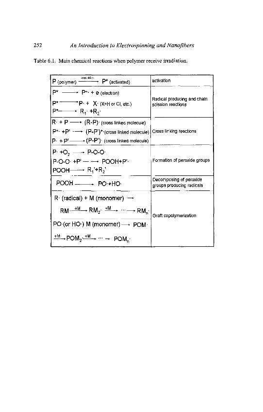
252 An Introduction to Electrospinning and Nanofibers
Table 6.1. Main chemical reactions when polymer receive irradiation.
irradiationP (polymer) • P* (activated) activation
P* • P+- + e (electron)Radical producing and chain
P* ' P - + X- (X=H or Cl, etc.) scission reactions
P* • FV +R2-
R- + P * (R-P)-(cross linked molecule)
p+. +p> K (P-P')+-(Cross linked molecule) Cross linking reactions
P- + P' • (P-P') ' (cross linked molecule)
P- +O2 • P-O-O-
P-O-O-+P' " POOH+P'- Formation of peroxide groups
POOH • Ri'+R2'
p O O H ^ p o + H n Decomposing of peroxider\j\jn » rU'trlU1 groups producing radicals
R- (radical) + M (monomer)—•
R M . ^ M _ R M 2 . ±*L_ • • - ^ R M .Graft copolymerization
PO(or HO) M (monomer)—• POM-
i ^ P O M 2 - ^ ^ ••• -* POMn-
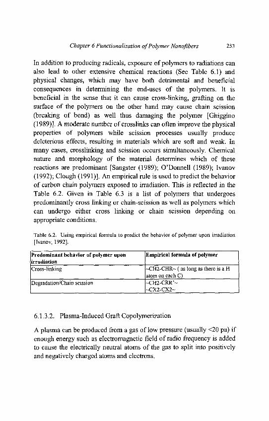
Chapter 6 Functionalization of Polymer Nanofibers 253
In addition to producing radicals, exposure of polymers to radiations canalso lead to other extensive chemical reactions (See Table 6.1) andphysical changes, which may have both detrimental and beneficialconsequences in determining the end-uses of the polymers. It isbeneficial in the sense that it can cause cross-linking, grafting on thesurface of the polymers on the other hand may cause chain scission(breaking of bond) as well thus damaging the polymer [Ghiggino(1989)]. A moderate number of crosslinks can often improve the physicalproperties of polymers while scission processes usually producedeleterious effects, resulting in materials which are soft and weak. Inmany cases, crosslinking and scission occurs simultaneously. Chemicalnature and morphology of the material determines which of thesereactions are predominant [Sangster (1989); O'Donnell (1989); Ivanov(1992); Clough (1991)]. An empirical rule is used to predict the behaviorof carbon chain polymers exposed to irradiation. This is reflected in theTable 6.2. Given in Table 6.3 is a list of polymers that undergoespredominantly cross linking or chain-scission as well as polymers whichcan undergo either cross linking or chain scission depending onappropriate conditions.
Table 6.2. Using empirical formula to predict the behavior of polymer upon irradiation[Ivanov, 1992].
Predominant behavior of polymer upon Empirical formula of polymerirradiationCross-linking ~CH2-CHR~ (as long as there is a H
atom on each C)Degradation/Chain scission ~CH2-CRR'~
1-CX2-CX2-
6.1.3.2. Plasma-Induced Graft Copolymerization
A plasma can be produced from a gas of low pressure (usually <20 pa) ifenough energy such as electromagnetic field of radio frequency is addedto cause the electrically neutral atoms of the gas to split into positivelyand negatively charged atoms and electrons.
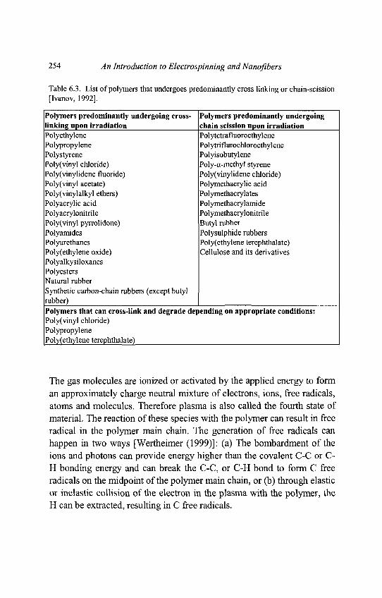
254 An Introduction to Electrospinning and Nanofibers
Table 6.3. List of polymers that undergoes predominantly cross linking or chain-scission[Ivanov, 1992].
Polymers predominantly undergoing cross- Polymers predominantly undergoinglinking upon irradiation chain scission upon irradiationPolyethylene PolytetrafluoroethylenePolypropylene PolytriflurochloroethylenePolystyrene PolyisobutylenePoly(vinyl chloride) Poly-a-methyl styrenePoly(vinylidene fluoride) Poly(vinylidene chloride)Poly(vinyl acetate) Polymethacrylic acidPoly(vinylalkyl ethers) PolymethacrylatesPolyacrylic acid PolymethacrylamidePolyacrylonitrile PolymethacrylonitrilePoly(vinyl pyrrolidone) Butyl rubberPolyamides Polysulphide rubbersPolyurethanes Poly(ethylene terephthalate)Poly(ethylene oxide) Cellulose and its derivativesPolyalkysiloxanesPolyestersNatural rubberSynthetic carbon-chain rubbers (except butylrubber)Polymers that can cross-link and degrade depending on appropriate conditions:Poly(vinyl chloride)PolypropylenePoly(ethylene terephthalate)
The gas molecules are ionized or activated by the applied energy to form
an approximately charge neutral mixture of electrons, ions, free radicals,
atoms and molecules. Therefore plasma is also called the fourth state of
material. The reaction of these species with the polymer can result in free
radical in the polymer main chain. The generation of free radicals can
happen in two ways [Wertheimer (1999)]: (a) The bombardment of the
ions and photons can provide energy higher than the covalent C-C or C-
H bonding energy and can break the C-C, or C-H bond to form C free
radicals on the midpoint of the polymer main chain, or (b) through elastic
or inelastic collision of the electron in the plasma with the polymer, the
H can be extracted, resulting in C free radicals.
Chapter 6 Functionalization of Polymer Nanofibers 255
When these activated polymer are exposed to monomers withunsaturated bond, the radicals on the polymer plays the role of initiatoras in conventional polymerization and makes polymerization started.Radicals are usually formed when the polymer are exposed to inert gases(such as argon or nitrogen) plasma. The treatment time usually is fromseveral to several ten seconds, depending on the kind of the polymer.After plasma treatment, the polymer should be immediately immersedinto the monomer solution to initiate the graft copolymerization. This isbecause the radicals produced on the polymer surface by the plasmatreatment will react with the oxygen molecules in the air to form a morestable peroxide groups, which can not directly initiate thepolymerization. Another strategy, however, is to let the plasma treatedpolymer exposed to open air or oxygen for more than lOmin to transferall the radicals to the peroxide groups, then using heating or UV todecompose the peroxide groups to initiate the copolymerization. Thisstrategy makes the graft polymerization much easier to perform and theresults more reproducible.
The plasma induced graft copolymerization has advantages such as: (i)Modification can be limited to the surface layer, leaving the properties ofthe bulk material unaltered. Typically, the modification depth is severalhundred angstroms, (ii) Nearly all polymer surfaces can be modified byplasma, no matter how the surface is composed, (iii) It is possible tochoose the type of chemical modification for the polymer through thechoice of gas used in gas plasma, (iv) Gas plasma treatment can avoidthe problems encountered in wet chemical techniques such as residualsolvent on the surface, (v) Plasma surface treatment is fairly uniformover the whole surface.
6.1.3.3. Oxidization-Induced Graft Copolymerization
Oxidization of polymer surface using O3 gas [Ying et. al. (2004)] orhydrogen peroxide solution [Ma et. al. (2002b)] can produce peroxidegroups, which can be used for graft copolymerization (Fig. 6.2). Ce (IV)is an oxidization agents often used for graft copolymerization onsubstrate surface containing hydroxyl groups [Ma et. al. (2005a)].
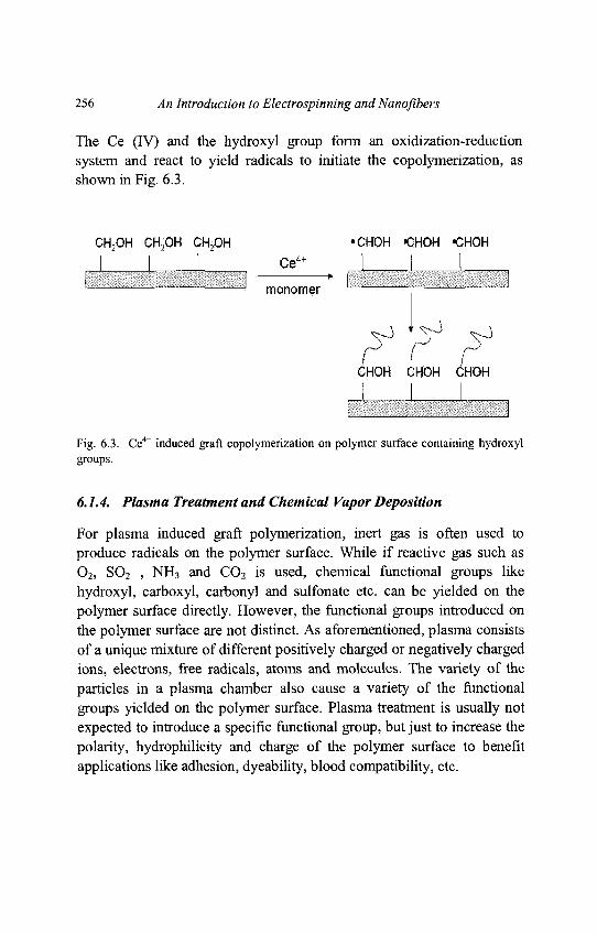
256 An Introduction to Electrospinning and Nanofibers
The Ce (IV) and the hydroxyl group form an oxidization-reductionsystem and react to yield radicals to initiate the copolymerization, asshown in Fig. 6.3.
Fig. 6.3. Ce4+ induced graft copolymerization on polymer surface containing hydroxylgroups.
6.1.4. Plasma Treatment and Chemical Vapor Deposition
For plasma induced graft polymerization, inert gas is often used toproduce radicals on the polymer surface. While if reactive gas such asO2, SO2 , NH3 and CO2 is used, chemical functional groups likehydroxyl, carboxyl, carbonyl and sulfonate etc. can be yielded on thepolymer surface directly. However, the functional groups introduced onthe polymer surface are not distinct. As aforementioned, plasma consistsof a unique mixture of different positively charged or negatively chargedions, electrons, free radicals, atoms and molecules. The variety of theparticles in a plasma chamber also cause a variety of the functionalgroups yielded on the polymer surface. Plasma treatment is usually notexpected to introduce a specific functional group, but just to increase thepolarity, hydrophilicity and charge of the polymer surface to benefitapplications like adhesion, dyeability, blood compatibility, etc.
Chapter 6 Functionalization of Polymer Nanofibers 257
Another kind of plasma treatment is plasma induced polymer deposition,which is different from the plasma induced graft copolymerizationdescribed above. In plasma induced polymer deposition, the monomergas is directly introduced into the plasma chamber and polymerized. Thepolymer generated in the gas phase is then deposited onto the substratesurface as a thin film [Mao and Gleason (2004)]. This method is actuallyone kind of the chemical vapor deposition (CVD) technique andtherefore is also called chemical vapor deposition polymerization(CVDP). CVD is a name for a broad of surface modification techniquesin which chemical reactions transform gaseous molecules, calledprecursor, into a solid material, in the form of thin film or powder, on thesurface of a substrate.
In a plasma aided CVD process, reactive gases of either high or lowtemperature are introduced into a plasma chamber and induced to formplasma. The resulted products deposited onto a low temperature substrateto form a thin solid film. Although the CVD process has been mainlyused to fabricate semiconductor devices, it is also an important method tomodify inert polymer surfaces like TFPE and PE [Lahann et. al. (2002)].
6.1.5. Chemical Treatment
Some polymer molecules possess functional groups like hydroxyl,carboxyl, amino and ester, etc. Such kind of polymer can be directlymodified by chemical treatment. Chemical modification involves theintroduction of one or more chemical species to a given surface so as toproduce a surface which has enhanced chemical and physical properties[Mottola(1992)].
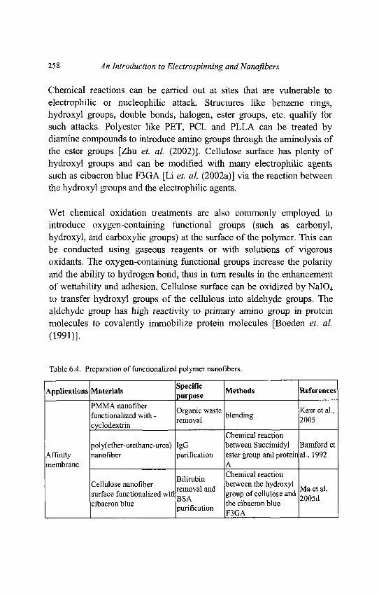
258 An Introduction to Electrospinning and Nanofibers
Chemical reactions can be carried out at sites that are vulnerable toelectrophilic or nucleophilic attack. Structures like benzene rings,hydroxyl groups, double bonds, halogen, ester groups, etc. qualify forsuch attacks. Polyester like PET, PCL and PLLA can be treated bydiamine compounds to introduce amino groups through the aminolysis ofthe ester groups [Zhu et. al. (2002)]. Cellulose surface has plenty ofhydroxyl groups and can be modified with many electrophilic agentssuch as cibacron blue F3GA [Li et. al. (2002a)] via the reaction betweenthe hydroxyl groups and the electrophilic agents.
Wet chemical oxidation treatments are also commonly employed tointroduce oxygen-containing functional groups (such as carbonyl,hydroxyl, and carboxylic groups) at the surface of the polymer. This canbe conducted using gaseous reagents or with solutions of vigorousoxidants. The oxygen-containing functional groups increase the polarityand the ability to hydrogen bond, thus in turn results in the enhancementof wettability and adhesion. Cellulose surface can be oxidized by NaIO4
to transfer hydroxyl groups of the cellulous into aldehyde groups. Thealdehyde group has high reactivity to primary amino group in proteinmolecules to covalently immobilize protein molecules [Boeden et. al.(1991)].
Table 6.4. Preparation of functionalized polymer nanofibers.
Applications Materials Methods Referencesr purposePMMA nanofiber _ „ . ,„ . .. , ., Organic waste , , ,. Kauretal.,functionalized with - , blending
, , . removal 2005cyclodextnn
Chemical reactionpoly(ether-urethane-urea) IgG between Succimidyl Bamford et
Affinity nanofiber purification ester group and protein al., 1992membrane A
Chemical reactionCellulose nanofiber , , between the hydroxyl .
. . . . . . ..removal and r „ , , Maetal,surface functionalized witl group of cellulose and -„„<-,
. , , , Dun i -i ii .Zv/vOClcibacron blue .„ . the cibacron blue
purification p 3 G A
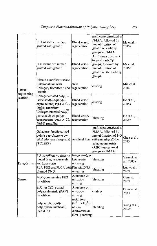
Chapter 6 Functionalization of Polymer Nanofibers 259
graft copolymerized ofncT c , f r>, j i PMAA, followed by ,PET nanofiber surface Bloodvessel . .... . r Maetal.,
c. , ... , . . immobilization of „„„-.grafted with gelatin regeneration , . , 2005agelatin on carboxylgroups in PMAAAir Plasma treatmentto yield carboxyl
PCL nanofiber surface Blood vessel groups, followed by Ma et al,grafted with gelatin regeneration immobilization of 2005b
gelatin on the carboxylgroups.
Fibroin nanofiber surfacefunctionalized with Skin . Min et al.,
_. Collagen, fibronectin and regeneration a ' ° 20041 issue .
lamimn.scaffold""8 C o l l a 8 e n - c o a t e d Poly(L-
lactic acid)-co-poly(e- Blood vessel . He et al.,caprolactone) P(LLA-CL regeneration c o a t i n g 2005a70:30) nanofiberCollagen-blended poly(L-lactic acid)-co-poly(e- Blood vessel , ,. He et al.,caprolactone) P(LLA-CL regeneration b l e n d l nS 2005b70:30) nanofiber
graft copolymerized ofGalactose functionalized PMAA, followed bypoly(e-caprolactone-co- immobilization of l-O-ethyl ethylene phosphate) Artificial liver (60-aminohexyl)-D- ^nns '(PCLEEP) galactopyranoside
(AHG) on carboxylgroups in PMAA
PU nanofibers containing Itraconazole or ,, . , . , . . Verreck et
model drug itraconazole ketansenn blending . . „„ ,Drug delivery and ketanserin releasing ''_
PLA-PEG and PLGA with PlasmidDNA , . .. Luuetal.,plasmid DND releasing o'ending 2003. , _ . . __ „ Ammonia or _
_ MoO3-containning PEO . Gouma,Sensor * e ratroxide blending . . „ -
nanofibers . s 2003sensing
SnO2 or TiO2 coated Ammonia or n t 1polyacrylonitrile (PAN) nitroxide coating -„„,nanofibers sensing
metal ionspoly(acrylic acid)- (Fe3+ or Hg2+) w ^ ^poly(pyrene methanol) or 2,4- blending 2002bmixed PU dinitrotoluene
(DNT) sensing |
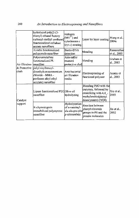
260 An Introduction to Electrospinning andNanofibers
hydrolyzed poly[2-(3- . ., . .. ., ,, viologen
thienyl) ethanol butoxy ,,,,,2+x _, , , , ,1 . 1 u i i n(MV )and . , , . Wangetal.,
carbonyl-methyl urethane] , Layer by layer coating „„„.. .. .. , „ , Jcytochromec J J J ° 2004Cfunctionahzed cellulose , .
_, (cyt c) sensingacetate nanofibersAividin functionalized Biotin-DNA , . ,. Ramanathaipolypyrrole nanofiber detection et al., 2005
Polyoxometallate Anti-sulfur _ ,. . . . , „ , , , , . ,. Graham etfunctionalized PU mustard blending
Air filtration nanofiber protective clotl '& Protective poly(vinylbenzyl-cloth dimethylcocoammonium Anti-bacterial * , , . _ • • r A t
. . . , . „ . . . -, . Electrospinning of Acatay etchloride - MMA - air filtration . . , , . . '
„ „ , , , ,• functional polymer al., 2003perfluoro alkyl ethyl mediaacrylate) nanofiber
Blending PEO with the. . . t. ,. ,„,,„.. .. enzymes, followed by v . , .Lipase functionalized PEC Olive oil . . . ... . , Xieetal.,
ru i. J i • crosshkingwith4,4 - __„,nanofiber hydrolyzmg . . . , . . , T 2003
methylenebis(phenylCatalyst diisocyanate) (MDI).support Hydrolyzation „ . ,F P , . ; • , Reaction between
R-chymotrypsm ofn-succinyl- , . . . , .. ., ... . , , , , phenyl nitroxide Jiaetal.,
immobilized polystyrene ala-ala-pro-phe p § a n d ^ 2QQ2
nanofiber p-mtroanihde . . , ,protein molecules
Chapter 6 Functionalization of Polymer Nanofibers 261
6.2. Functionalization of Nanofibers for Different Applications
6.2.1. Introduction
All the current techniques motioned above may be considered for thesurface modification of polymer nanofibers, but with one problem to benoticed: the polymer nanofibers must be protected from being destroyed.Strong reaction conditions like plasma, UV, y radiation, hightemperature, acidic or basic environment may destroy the polymernanofibers easily, especially when the polymer nanofiber isbiodegradable. Biodegradable polymers like PLA and PGA nanofibersmay have much faster degradation rate compared with the macro- ormicro-scale materials due to the high surface area. Even PET showedconsiderable degradation rate when it is prepared into nanofibers.Therefore, the reaction condition for the surface modification of polymernanofibers must be optimized to preserve the nanofibrous morphology.Some surface modification methods like molecular self-assembly [Zhanget. al. (1999); Pakalns et. al. (1999)] and "layer by layer" electrostaticinteraction [Wang et. al. (2004c); Zhu et. al. (2003)] can be performedunder very moderate conditions, thus may be the most potential methodsfor surface modification of biodegradable polymer nanofibers.Table 6.4 gives a summarization of works on the functionalization ofnanofibers and their respective applications.
6.2.2. Functionalization of Nanofibers for Affinity MembraneApplication
One main interest of electrospun polymer nanofiber nonwoven mesh isfor affinity membrane applications. Affinity membrane is membranewhich bases its separation on the selectivity of the membrane to 'capture'molecules, by immobilizing specific ligands onto the membrane surface.For the nanofiber mesh to be used as affinity membrane, specific ligandmolecules need to be immobilized on the nanofiber surface.
262 An Introduction to Electrospinning and Nanofibers
The simplest method to introduce ligands on nanofiber surface is todirectly mixing the ligand molecules into the polymer solution and thenelectrospin the polymer solution. An attempt by Kaur et al. has beenmade to incorporate chemically modified P-CD onto the surface of thenanofiber to target potential applications in organic waste treatment forwater purification [Kaur et. al. (2005)].
Phenylcarbomylated or azido phenylcarbomylated P-CD wassuccessfully blended with PMMA and electrospun into nanofibrousmembrane respectively. The presence of the P-CD derivatives on thesurface of the nanofibers was confirmed by ATR-FTIR and XPS (Fig.6.4).
To determine the functionalized membranes ability to capture smallorganic molecules, a solution containing phenolphthalein (PHP), a smallorganic molecule, was used. The functionalized nanofibrous membraneswere able to capture the PHP molecules effectively. Thus thefunctionalized nanofibrous membranes may have the potential to capturesimilar small organic waste molecules present in water.
A study has been presented on the potentials of electrospun poly(ether-urethane-urea) as an affinity separation membrane [Bamford et. al.(1992)]. Succimidyl ester group containing polyurethane has beenprepared and the succimidyl groups were reacted with protein A for thefunctionalization of the membrane surfaces.
Assessments of the capacities of the reactive membranes for covalentcoupling of protein A and human immunoglobulin G gave veryencouraging data, 4mg/g for protein A and 4mg/g for bounded IgG,respectively.
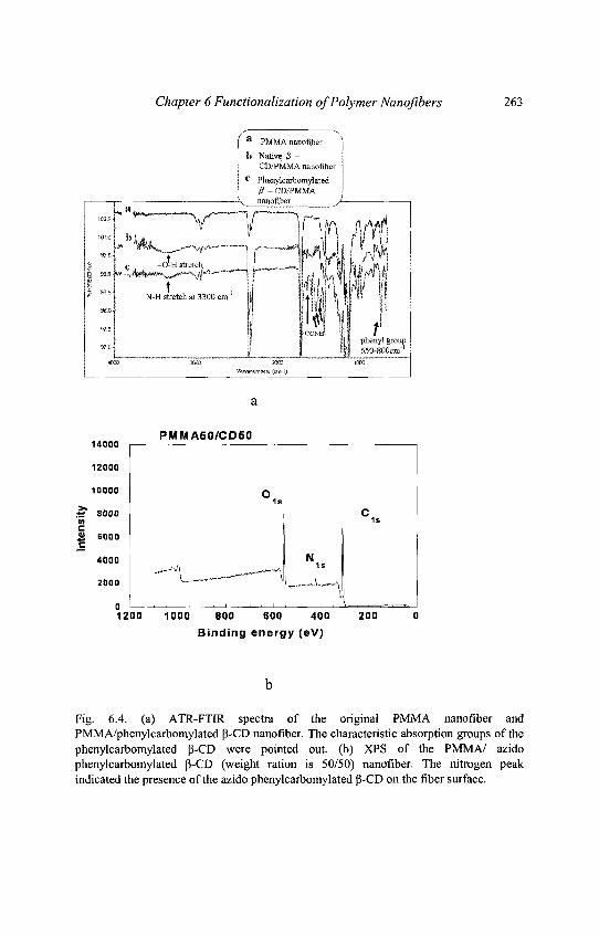
Chapter 6 Functionalization of Polymer Nanofibers 263
Fig. 6.4. (a) ATR-FTIR spectra of the original PMMA nanofiber andPMMA/phenylcarbomylated p-CD nanofiber. The characteristic absorption groups of thephenylcarbomylated P-CD were pointed out. (b) XPS of the PMMA/ azidophenyicarbomylated p-CD (weight ration is 50/50) nanofiber. The nitrogen peakindicated the presence of the azido phenylcarbomylated P-CD on the fiber surface.
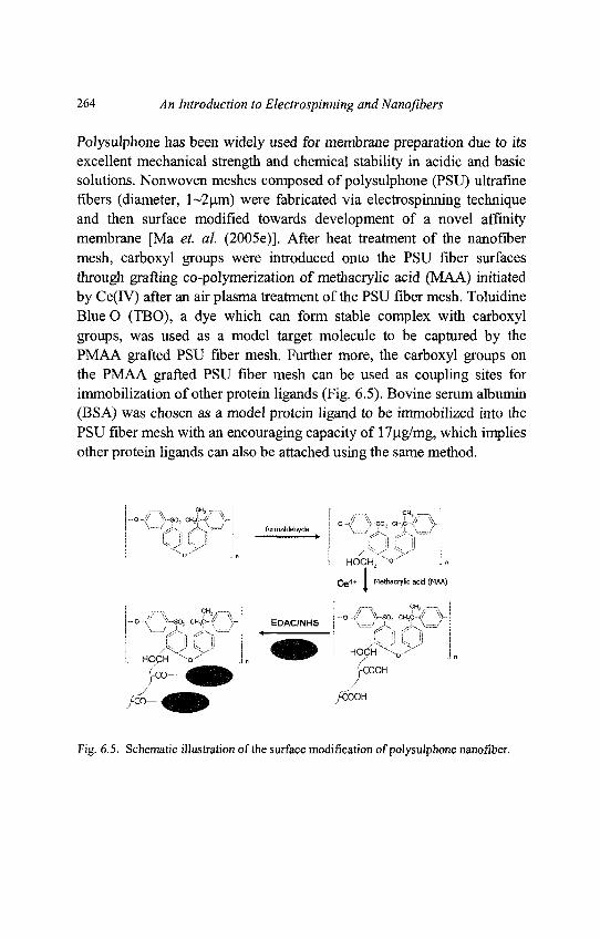
264 An Introduction to Electrospinning and Nanofibers
Polysulphone has been widely used for membrane preparation due to itsexcellent mechanical strength and chemical stability in acidic and basicsolutions. Nonwoven meshes composed of polysulphone (PSU) ultrafinefibers (diameter, l~2(^m) were fabricated via electrospinning techniqueand then surface modified towards development of a novel affinitymembrane [Ma et. al. (2005e)]. After heat treatment of the nanofibermesh, carboxyl groups were introduced onto the PSU fiber surfacesthrough grafting co-polymerization of methacrylic acid (MAA) initiatedby Ce(IV) after an air plasma treatment of the PSU fiber mesh. ToluidineBlue O (TBO), a dye which can form stable complex with carboxylgroups, was used as a model target molecule to be captured by thePMAA grafted PSU fiber mesh. Further more, the carboxyl groups onthe PMAA grafted PSU fiber mesh can be used as coupling sites forimmobilization of other protein ligands (Fig. 6.5). Bovine serum albumin(BSA) was chosen as a model protein ligand to be immobilized into thePSU fiber mesh with an encouraging capacity of 17|ig/mg, which impliesother protein ligands can also be attached using the same method.
Fig. 6.5. Schematic illustration of the surface modification of polysulphone nanofiber.
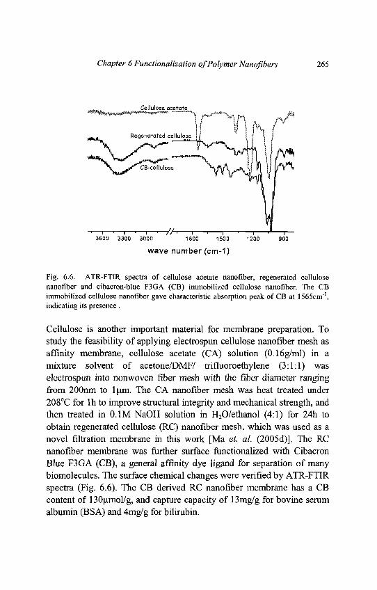
Chapter 6 Functionalization of Polymer Nanofibers 265
Fig. 6.6. ATR-FTIR spectra of cellulose acetate nanofiber, regenerated cellulosenanofiber and cibacron-blue F3GA (CB) immobilized cellulose nanofiber. The CBimmobilized cellulose nanofiber gave characteristic absorption peak of CB at 1565cm1,indicating its presence .
Cellulose is another important material for membrane preparation. Tostudy the feasibility of applying electrospun cellulose nanofiber mesh asaffinity membrane, cellulose acetate (CA) solution (0.16g/ml) in amixture solvent of acetone/DMF/ trifluoroethylene (3:1:1) waselectrospun into nonwoven fiber mesh with the fiber diameter rangingfrom 200nm to \\iva. The CA nanofiber mesh was heat treated under208°C for lh to improve structural integrity and mechanical strength, andthen treated in 0.1M NaOH solution in H2O/ethanol (4:1) for 24h toobtain regenerated cellulose (RC) nanofiber mesh, which was used as anovel filtration membrane in this work [Ma et. al. (2005d)]. The RCnanofiber membrane was further surface functionalized with CibacronBlue F3GA (CB), a general affinity dye ligand for separation of manybiomolecules. The surface chemical changes were verified by ATR-FTIRspectra (Fig. 6.6). The CB derived RC nanofiber membrane has a CBcontent of 130umol/g, and capture capacity of 13mg/g for bovine serumalbumin (BSA) and 4mg/g for bilirubin.
266 An Introduction to Electrospinning and Nanofibers
6.2.3. Functionalization of Nanoflber for Tissue Engineering ScaffoldApplication
Polymeric nanofiber matrix has similar structure with the nano-scalednonwoven fibrous extra cellular matrix (ECM) proteins, thus is awonderful candidate for ECM-mimic tissue engineering scaffold [Ma et.al. (2005c)]. A successful tissue engineering scaffold should have cellcompatible surfaces to allow cell attachment and proliferation. Most ofthe surface modification works to improve biocompatibilities ofpolymeric tissue engineering scaffold center on immobilizations ofbiomolecules that can be specifically recognized by cells on thebiomaterials [Elbert and Hubbell (1996)]. These biomolecules includeadhesive proteins like collagen, fibronectin, RGD peptides and growthfactors like bFGF, EGF, insulin, etc. The biomolecules can either becovalently attached, electrostatically adsorbed or self-assembled on thebiomaterial surfaces.
Collagen, fibronectin and laminin have been coated on electrospun silkfibroin nanofiber surface to promote cell adhesion [Min et. al. (2004)].Collagen-coated poly(L-lactic acid)-co-poly(e-caprolactone) P(LLA-CL70:30) nanofiber mesh (NFM) with diameter of 470 nm and porosity of64-67 % was fabricated using electrospinning followed by the plasmatreatment and collagen coating. The spatial distribution of the collagen inthe NFM was visualized by labeling the collagen with fluorescent dyeand it was found that the collagen can be uniformly coated around thepolymer nanofiber. Endothelial cells were seeded onto the collagen-coated P(LLA-CL) nanofiber and the results showed that the collagencoated material have higher cell attachment, spreading and viability thanthe unmodified nanofiber. [He et. al. (2005a)].
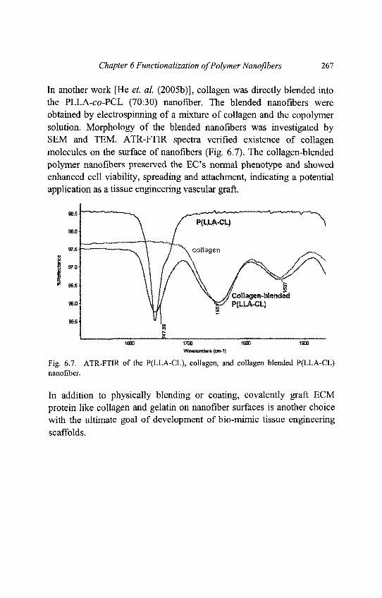
Chapter 6 Functionalization of Polymer Nanofibers 267
In another work [He et. al. (2005b)], collagen was directly blended intothe PLLA-co-PCL (70:30) nanofiber. The blended nanofibers wereobtained by electrospinning of a mixture of collagen and the copolymersolution. Morphology of the blended nanofibers was investigated bySEM and TEM. ATR-FTIR spectra verified existence of collagenmolecules on the surface of nanofibers (Fig. 6.7). The collagen-blendedpolymer nanofibers preserved the EC's normal phenotype and showedenhanced cell viability, spreading and attachment, indicating a potentialapplication as a tissue engineering vascular graft.
Fig. 6.7. ATR-FTIR of the P(LLA-CL), collagen, and collagen blended P(LLA-CL)nanofiber.
In addition to physically blending or coating, covalently graft ECMprotein like collagen and gelatin on nanofiber surfaces is another choicewith the ultimate goal of development of bio-mimic tissue engineeringscaffolds.
268 An Introduction to Electrospinning and Nanofibers
One popular methods to covalently attach protein molecules on polymersurface is to graft poly(methacrylic acid) on the biomaterial surface tointroduce carboxyl groups at first, followed by the grafting of the proteinmolecules using water soluble carbodiimide as coupling reagent[Steffensa et. al. (2002); Ma et. al. (2002a)]. Non-woven PET nanofibermeshes has been prepared by electrospinning technology and surfacegrafted with gelatin. The PET nanofiber was first treated informaldehyde to yield hydroxyl groups on the surface, followed by thegrafting polymerization of methacrylic acid (MAA) initiated by Ce (IV).Finally the PMAA grafted PET nanofiber was grafted with gelatin usingwater-soluble carbodiimide as coupling agent [Ma et. al. (2005a)]. Forgelatin grafting on PCL nanofiber surfaces, the PCL nanofiber was firsttreated with air plasma to introduce -COOH groups on the surfacefollowed by covalently grafting of gelatin molecules [Ma et. al. (2005b)].Both the gelatin modified PET and PCL nanofibers showed improvedendothelial cell compatibility than the unmodified nanofibers. Moreover,the gelatin modified aligned PCL nanofiber also showed strong abilitiesto affect endothelial cell orientation.
Chua et. al., used UV radiation induced graft co-polymerization todevelop a biofunctional poly(e-caprolactone-co-ethyl ethylenephosphate) (PCLEEP) nanofiber construct for hepatocyte culture [Chuaet. al. (2005)]. This was achieved by conjugating hepatocyte-specificgalactose ligands onto nanofiber surface. Poly(acrylic acid) was graftedonto the nanofiber scaffold via UV-induced polymerization using acrylicacid (AAc) monomers. The COOH sites on the grafted scaffold was thenused as immobilization sites to conjugate l-O- (60-aminohexyl)-D-galactopyranoside (AHG). The functionalized AHG-P(AAc)-graftednanofiber scaffolds exhibited much higher hepatocyte attachment ascompared to unmodified scaffold. Such nanofiber scaffolds would beadvantageous in the design of a bioartificial liver-assist device, where thehepatocytes could attach to a scaffold with high surface area immobilizedwith a cell-specific ligand, maintain their differentiated functions, andremain stable against the perfusion and shear forces in the bioreactor.
Chapter 6 Functionalization of Polymer Nanofibers 269
6.2.4. Functionalization of Nanofibers for Sensor Application
Sensor means devices that respond to physical or chemical stimulus suchas biomolecules concentration, gas concentration, thermal energy,electromagnetic energy, acoustic energy, pressure, magnetism, ormotion, by producing an easily detectable and measurable signal, usuallyelectrical or optical. Electrospun nanofiber received great researchinterests for sensor application due to its unique high surface area. Highsurface area is one of the most desired parameters for the sensitivity ofconductimetric sensor film. Conductimetric sensor based on semi-conducting oxides is a kind of low cost detectors for reductive gas. Theoperating principle of these devices is associated primarily with theadsorption of the gas molecules on the surface of semiconducting oxidesinducing electric charge transport between the two materials, thatchanges the resistance of the oxide. The structure configuration of themetal oxide materials is one of the key parameters controlling the gassenescing process. Now there is an increasing trend in chemical sensingto utilize nanostructured materials as gas sensing elements because thehigh surface areas and the unique structure features are expected topromote the sensitivity of the metal oxide to the gaseous component.For the polymer nanofibers to be used as the above describedconductimetric sensor, it should be functionalized with metal oxidesemiconductors. Gouma produced MoO3-containning PEO nanofibers byelectrospin a mixture of MoO3 so-gel and PEO solution [Gouma (2003)].Gas sensing test of the electrospun nanofiber mat was carried out usingammonia and nitroxide as model gas. Electrical resistance of the sensingfilm as a function of the gas concentration was measured and the resultsshowed that the nanoscaled metal oxide fiber offer high sensitivity andfast response to the harmful chemical gases. Drew coated SnO2 and TiO2
on polyacrylonitrile (PAN) nanofibers using a "liquid-phase deposition"technique. The coatings were thin enough to maintain the nanofibrousmorphology, thereby retaining the large surface area of the electrospunmembrane [Drew et. al. (2003)]. Such metal oxide-coated nanofibrousmembranes are expected to provide unusual and highly reactive surfacesfor improved sensing, catalysis and photoelectric conversionapplications.
270 An Introduction to Electrospinning and Nanofibers
Single polyprrole nanofiber containing avidin with diameters of lOOnmand 200nm were produced by electrospinning avidin-blended polyprrolesolution. The single nanofiber was studied as biosensors for detectingbiotin labeled biomolecules such as DNA. Exposing of the avidinfunctionalized single polyprrole nanofiber to the biotin labeledbiomolecules will allow the binding between the avidin molecules andthe biotin groups, changing the electric resistance of the single nanofiber.Thus the nanofiber was a novel nano-sensor for biomolecule detection[Ramanathan et. al. (2005)].
Wang report the first application of electrospun nanofibrous membranesas highly responsive fluorescence quenching-based optical sensors[Wang et. al. (2002b)]. A fluorescent polymer, poly(acrylic acid)-poly(pyrene methanol) (PAA-PM), was used as a sensing material.Optical chemical sensors were fabricated by electrospinning PAA-PMand thermally cross-linkable polyurethane latex mixture solutions. Thefluorescence can be quenched by metal ions (Fe3+ and Hg2+) and 2,4-dinitrotoluene (DNT) so the nanofibrous material can be used as sensorto detect the substances. These sensors showed high sensitivities due tothe high surface area-to-volume ratio of the nanofibrous membranestructures.
In another work [Wang et. al. (2004c)], a fluorescent probe, hydrolyzedpoly[2-(3-thienyl) ethanol butoxy carbonyl-methyl urethane] (H-PURET) was immobilized on the cellulose acetate electrospunnanofibrous membranes using "layer by layer" electrostatically self-assembly method. Also by the quenching mechanism, the nanofiber canby use as optical sensor to detect trace amount of methyl viologen andcytochrome c in aqueous solutions. The high sensitivity is attributed tothe high surface-area-to-volume ratio of the electrospun membranes andefficient interaction between the fluorescent conjugated polymer and theanalytes.
Chapter 6 Functionalization of Polymer Nanofibers 271
6.2.5. Functionalization of Nanofiber for Protective Cloth Application
There exists a great potential in the polymer nanofibers for use as aerosolfilters in face masks and in protective clothing against chemical andbiological warfare agents [Gibson et. al. (1999); Schreuder-Gibson, et.al. (2002)]. Polymeric nanofibers have been studied as a carrier foractive chemistry that may allow for improvements in chemical protectiveproperties. The nanofibers can provide a huge surface area to befunctionalized with chemical groups, which are reactive with toxic gasesand chemicals. Graham mixed polyoxometallate, a catalyst for theoxidative degradation of sulfur mustard (a chemical weapon agent) withthe PU (EstaneTM 58238) solution and electrospun the mixture intonanofibers. The capability of the catalyst in the electrospun nanofiberwas found even higher than the catalyst alone [Graham et. al. (2003)].
Acatay synthesized an antibacterial agent (quaternary ammonium salt)containing perfluorinated terpolymer, poly(vinylbenzyl-dimethylcocoammonium chloride - MMA - perfluoro alkyl ethylaery late). This terpolymer was electrospun into a fluffy nanofiber meshwith fiber diameter as low as 40nm. The nanofiber was immersed intoliquid solutions containing Escherichia Coli to test the anti-bacterialability. Although the antibacterial activity in liquid solution was detectedto be weak due to its low surface tension, the material may be used in airfiltration applications [Acatay et. al. (2003)].
Two of the most common classes of chemical warfare agents include thenerve agents (Organophosphorus compounds) and the blister agents(Mustard gas). The motivation of develop a novel protective cloth usingelectrospun polymer nanofiber is to impart a functional group into/ontothe nanofiber surface in such a way that when the gases come intocontact, by chemical reaction on the surface of the nanofibers, theiractive groups get deactivated into relatively harmless by-products.Additionally these nanofibers would have sufficient resistance to blockthe bacterial contaminants such as Bacillus Anthracis by virtue of smallpore size.
272 An Introduction to Electrospinning and Nanofibers
For nerve gases, the reactive moiety is the organophosphorus group. Thiscould be deactivated by hydrolysis. The hydrolyzing agent chosen forthis purpose is the oxime moiety (Fig. 6.8). Polymer contained in asolvent would be treated with the appropriate compounds and the oximegroup would be attached to the polymer backbone. The functionalizedpolymer solution is then electrospun into fibers which contain thereactive oxime groups. The oxime functionality would aid in hydrolysisof the organophosphate group into mild organic acids and secondaryalcohols. Another approach proposed is to modify the electrospunnanofiber surface with enzymes which catalyze hydrolysis ofOrganophosphorus agents such as Organophosphorus hydrolase andAcetylcholine esterase. The enzyme can be regenerated by washing theused up fibers in a lean solution containing oxime groups which re-activates the functional agent. However, the oxime modified fiberswould possess longer shelf life and activity compared to the enzymesurface modification due to the fact that enzymes denature at a rapidpace.
Fig. 6.8. Hydrolyzation of phosphorous organic nerve agent by oxime groups.
ci Y ci
™N = <^H~r-iP> = N H chloramine compounda _T^ • ci
y S-330 „ & *HC!
Mustard GasNon-Toxic Products
Fig. 6.9. Oxidization of Mustard gas by chloramines compound.
Chapter 6 Functionalization of Polymer Nanoflbers TTi
Mustard gas detoxification can be attempted by two pathways, hydrolysisand oxidation. Oxidation pathway is however proposed [McCreery andMichael (1995)] as the hydrolysis reaction leaves behind products thatare not entirely safe. Oxidation of mustard gas is by using chloraminefunctionality (Fig. 6.9). Polymer would be blended with the reagent andby substitution reaction the chloramine functionality would be impartedonto the polymer backbone, this would be electrospun into fibers. Whenthe fibers come into contact with an aerosol containing the mustard gas,it would oxidize the latter into mild non-toxic by products. The oximefunctionality and the chloramine functionality also inherently possessbactericidal and fungicidal activity which helps in prevention of fungalgrowth or entry of bacteria into the mask. The nanofiber filter can befabricated in such a way that the maximum pore size lies in the submicron level, which is small compared to the size of bacterial spores.Thereby, bacterial warfare agents also get eliminated.
6.2.6. Functionalization of Nanoflbers for Other Applications
Due to its higher surface area to volume ratio, nanofiber has been studiedfor applications as drug delivery carriers and catalyst support. Theblending (or mixing) technique is a common choice for the nanofiberfunctionalization. Drugs, growth factors and genes can be directly mixedinto the polymer solution and electrospun to prepare drug carriers withcontrolled release properties. Verreck prepared PU nanoflbers containingmodel drug itraconazole and ketanserin, using dimethylformide (DMF)and dimethylacetamide (DMAc) as solvent, respectively. The releasingof the drug showed liner relation with the time [Verreck et. al. (2003a)].Luu mixed plasmid with PLA-PEG and PLGA solution in DMF andelectrospun the mixture into nanoflbers. Release of plasmid DNA fromthe scaffolds was sustained over a 20-day study period, with maximumrelease occurring at 2 h [Luu et. al. (2003)].
274 An Introduction to Electrospinning and Nanofibers
Improvement of catalytic efficiency of immobilized enzymes onnanofiber surface was demonstrated. R-chymotrypsin was chemicallyattached on polystyrene (PS) nanofibers derived with phenyl nitroxidegroups and examined for catalytic efficiency to hydrolyze modelcompound, n-succinyl-ala-ala-pro-phe /?-nitroanilide. The apparenthydrolytic activity of the nanofibrous enzyme in aqueous solutions wasover 65% of that of the native enzyme, indicating a high catalyticefficiency as compared to other forms of immobilized enzymes [Jia et.al. (2002)]. In Xie's work [Xie et. al. (2003)], the mixture of lipase andpoly(ethylene oxide) (PEO) or poly(vinyl alcohol) (PVA) waselectrospun into ultra-thin fibrous membranes. The fibrous membraneswere rendered insoluble by chemical crosslinking with 4,4_-methylenebis(phenyl diisocyanate) (MDI). The lipase encapsulated in theultra-fine fibrous membranes exhibits higher catalytic activity towardshydrolyzing olive oil than that in the cast films from the same solution.
6.3. Conclusions
Electrospun polymer nanofiber is receiving an extensive research interestfor diverse applications. However, most of the polymer nanofibers do notpossess any specific functional groups and they must be specificallyfunctionalized for successful applications. Currently available techniquesfor polymer surface modification like blending or coating, graftcopolymerization and plasma treatment have be used for thefunctionalization of polymer nanofibers.The reaction conditions should be controlled properly to prevent thenanofiber morphology from being destroyed.
The most popular and simplest nanofiber modification methods arephysical blending and coating. Surface grafting polymerization has alsobeen used for attaching ligands molecules and adhesive proteins onnanofiber surface for application of affinity membrane and tissueengineering scaffold, respectively.
Chapter 7
Potential Applications
7.1. Introduction
As introduced in previous chapters, much effort has been applied toelectrospun polymer nanofibers to comprehend the fundamentalphenomena of fabrication process as well as the physical and chemicalproperties from the material science viewpoint. Fig. 7.1 shows that 60%of electrospun polymer nanofiber researches have been devoted to thestudies of their processing and characterization. Consequently, nanofiberresearchers are able to flexibly control the fiber morphology, fiberdiameter and patterning of fiber deposition. These developments haveprovided much impetus to the dream of realizing the potentialapplications of nanofibers. As seen in Fig. 7.1, major possibleapplications are categorized into Bioengineering, EnvironmentalEngineering & Biotechnology, Energy & Electronics and Defense &Security. In all areas, the demand of new novel materials has beenaspired and electrospun polymer nanofibers could make the new wave ofmaterial research.
275
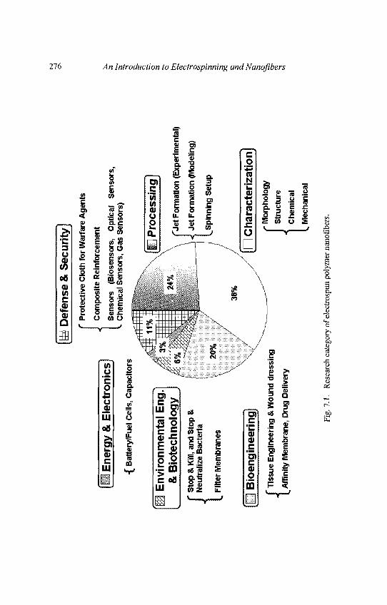
Def
ense
& S
ecur
ity
I E
nerg
y &
Ele
ctro
nics
]
-f B
atte
ry/F
uel C
ells
, Cap
acito
rs
f P
rote
ctiv
e C
loth
for W
arfa
re A
gent
s
J C
ompo
site
Rei
nfor
cem
ent
Sen
sors
(B
iose
nsor
s,
Opt
ical
S
enso
rs,
v. C
hem
ical
Sen
sors
, Gas
Sen
sors
)
Env
ironm
enta
l Eng
& B
iote
chno
logy
Sto
p &
Kill
, and
Sto
p &
Neu
traliz
e B
acte
ria
Filt
er M
embr
anes
Bio
engi
neer
ing
j T
issu
e E
ngin
eerin
g &
Wou
nd d
ress
ing
(_ A
ffini
ty M
embr
ane,
Dru
g D
eliv
ery
C P
roce
ssin
g
["Jet
For
mat
ion
(Exp
erim
enta
l)
J Je
t For
mat
ion
(Mod
elin
g)
(.S
pinn
ing
Set
up
Cha
ract
eriz
atio
n)r
Mor
phol
ogy
I S
truc
ture
| C
hem
ical
L M
echa
nica
l
Fig.
7.1
. R
esea
rch
cate
gory
of e
lect
rosp
un p
olym
er n
anof
iber
s.
276 An Introduction to Electrospinning and Nanofibers
Chapter 7 Potential Applications 277
Nanofiber researches in bioengineering consists of tissue engineering andwound dressing, affinity membrane and drug delivery. These fields havegained great interest since the percentage of senior citizens has beenprojected to increase dramatically in this century. For tissue engineeringand wound dressing, electrospun polymer nanofibers are treated as tissuescaffolds which enhance cell growth and proliferation.
The nanofiber scaffolds with seeded cells can be implanted to patient'sbody to repair the damaged tissues. For drug delivery system, nanofibersare considered as a potential drug carrier. Here, nanofibrous membranesincorporated with drug component can be patched on wound of surgeryor encapsulated into pharmaceutical capsules to deliver the drug throughdigestive system of patient. Affinity membranes have a function toseparate the targeted bio-molecule using ligands chemically attached onthe nanofiber surface. As compared to conventional filtration column,nanofibrous affinity membranes are expected to realize high efficientseparation due to high surface area of nanofibers.
For environmental engineering, the function of nanofibrous membranesis to filter moisture and dusts. Unclean air which contains bacteria can bealso purified using nano-size level fibrous membranes. Here, if thesurface of nanofibers is chemically modified to kill bacteria, such anti-bacteria filter media is useful to protect people in residence and office.
In view of the increasing level of awareness towards national security atthe turn of the millennium, the United Nations (UN) occasionally sendsthe troop for peace keeping operative (PKO) purpose, hi suchcircumstances, electrospun nanofiber has found its potential applicationas protective clothing for the soldiers' safety. Such novel protectiveclothing can capture and neutralize harmful chemical and biologicalwarfare agents. So far there have been no publications which discusssuch nanofibrous protective clothing. As such, the background and theconcept of nanofibrous protective clothing is introduced in this chapter.Sensors for detecting toxic gases are also possible application ofnanofibers for this category of defense.
278 An Introduction to Electrospinning and Nanofibers
Nanofibers made of sensing materials may show the excellent sensingbehavior within short operating time. It is acknowledged that some of theparts of army constructions as well as transporting aero planes are madeof polymer based composite materials. Conventional composite materialspossess micron-size carbon, glass and aramid reinforcement fibers. It isconsidered that electrospun nanofibers with high surface area can supplybetter efficient reinforcement and may be possible to achieve excellentmechanical performance.
In this century, the economy of developing countries such as China andIndia has been healthily expanding, thereby causing the energyconsumption to increase. Several eco-clean energy resources, such aswind generator, solar generator, hydrogen battery and polymer batteryhave been investigated so far. With respect polymer battery, researcher'sdesire has been placed on the battery assembled with polymernanofibrous membranes as new generation energy.
Thus, in this chapter, abovementioned potential applications ofelectrospun polymer nanofiber are introduced and the research trend ofeach topic is briefly analyzed.
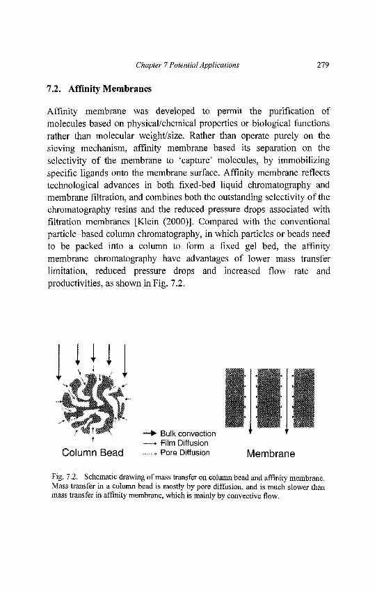
Chapter 7 Potential Applications 279
7.2. Affinity Membranes
Affinity membrane was developed to permit the purification ofmolecules based on physical/chemical properties or biological functionsrather than molecular weight/size. Rather than operate purely on thesieving mechanism, affinity membrane based its separation on theselectivity of the membrane to 'capture' molecules, by immobilizingspecific ligands onto the membrane surface. Affinity membrane reflectstechnological advances in both fixed-bed liquid chromatography andmembrane filtration, and combines both the outstanding selectivity of thechromatography resins and the reduced pressure drops associated withfiltration membranes [Klein (2000)]. Compared with the conventionalparticle-based column chromatography, in which particles or beads needto be packed into a column to form a fixed gel bed, the affinitymembrane chromatography have advantages of lower mass transferlimitation, reduced pressure drops and increased flow rate andproductivities, as shown in Fig. 7.2.
Fig. 7.2. Schematic drawing of mass transfer on column bead and affinity membrane.Mass transfer in a column bead is mostly by pore diffusion, and is much slower thanmass transfer in affinity membrane, which is mainly by convective flow.
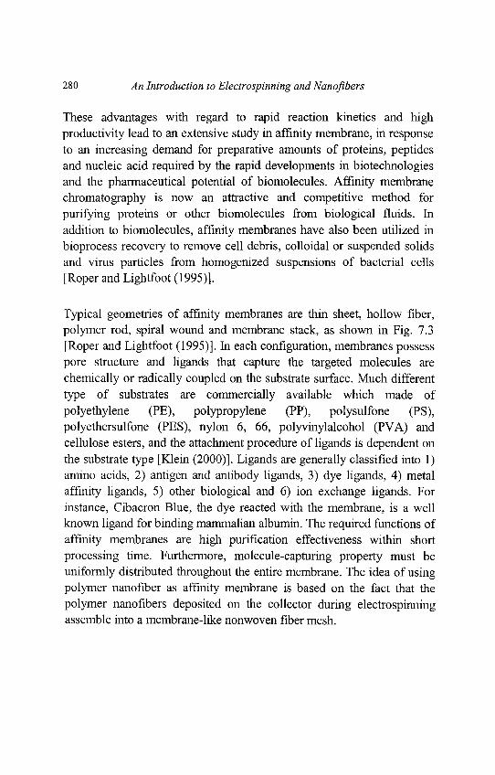
280 An Introduction to Electrospinning and Nanofibers
These advantages with regard to rapid reaction kinetics and highproductivity lead to an extensive study in affinity membrane, in responseto an increasing demand for preparative amounts of proteins, peptidesand nucleic acid required by the rapid developments in biotechnologiesand the pharmaceutical potential of biomolecules. Affinity membranechromatography is now an attractive and competitive method forpurifying proteins or other biomolecules from biological fluids. Inaddition to biomolecules, affinity membranes have also been utilized inbioprocess recovery to remove cell debris, colloidal or suspended solidsand virus particles from homogenized suspensions of bacterial cells[Roper and Lightfoot (1995)].
Typical geometries of affinity membranes are thin sheet, hollow fiber,polymer rod, spiral wound and membrane stack, as shown in Fig. 7.3[Roper and Lightfoot (1995)]. In each configuration, membranes possesspore structure and ligands that capture the targeted molecules arechemically or radically coupled on the substrate surface. Much differenttype of substrates are commercially available which made ofpolyethylene (PE), polypropylene (PP), polysulfone (PS),polyethersulfone (PES), nylon 6, 66, polyvinylalcohol (PVA) andcellulose esters, and the attachment procedure of ligands is dependent onthe substrate type [Klein (2000)]. Ligands are generally classified into 1)amino acids, 2) antigen and antibody ligands, 3) dye ligands, 4) metalaffinity ligands, 5) other biological and 6) ion exchange ligands. Forinstance, Cibacron Blue, the dye reacted with the membrane, is a wellknown ligand for binding mammalian albumin. The required functions ofaffinity membranes are high purification effectiveness within shortprocessing time. Furthermore, molecule-capturing property must beuniformly distributed throughout the entire membrane. The idea of usingpolymer nanofiber as affinity membrane is based on the fact that thepolymer nanofibers deposited on the collector during electrospinningassemble into a membrane-like nonwoven fiber mesh.
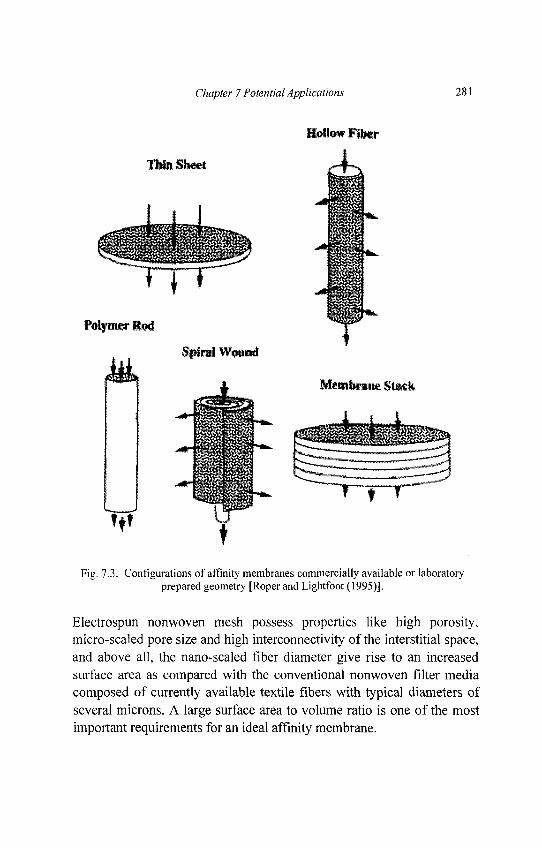
Chapter 7 Potential Applications 281
Fig. 7.3. Configurations of affinity membranes commercially available or laboratoryprepared geometry [Roper and Lightfoot (1995)].
Electrospun nonwoven mesh possess properties like high porosity,micro-scaled pore size and high interconnectivity of the interstitial space,and above all, the nano-scaled fiber diameter give rise to an increasedsurface area as compared with the conventional nonwoven filter mediacomposed of currently available textile fibers with typical diameters ofseveral microns. A large surface area to volume ratio is one of the mostimportant requirements for an ideal affinity membrane.
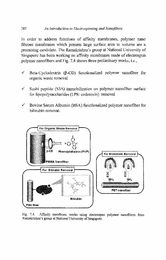
282 An Introduction to Electrospinning and Nanofibers
In order to address functions of affinity membranes, polymer nanofibrous membranes which possess large surface area to volume are apromising candidate. The Ramakrishna's group at National University ofSingapore has been working on affinity membranes made of electrospunpolymer nanofibers and Fig. 7.4 shows three preliminary works, i.e.,
S Beta-Cyclodextrin (p-CD) functionalized polymer nanofiber fororganic waste removal
S Sushi peptide (S3A) immobilization on polymer nanofiber surfacefor lipopolysaccharides (LPS: endotoxin) removal
S Bovine Serum Albumin (BSA) functionalized polymer nanofiber forbilirubin removal.
Fig. 7.4. Affinity membrane works using electrospun polymer nanofibers fromRamakrishna's group at National University of Singapore.
Chapter 7 Potential Applications 283
Fig. 7.5. UV/VIS absorbance of PHP on p-CD modified polymethylmethacrylate(PMMA) nanofibrous membranes [Courtesy of Ma and Ramakrishna at NationalUniversity of Singapore].
For p-CD functionalization, phenolphthalein (PHP) was used as a modelof organic waste and the capturing property of polymehtylmethacrylate(PMMA) nanofiber membranes was discussed as shown in Fig. 7.5. Itwas shown that UV/VIS absorbance of PHP decreased with increasingthe amount of P-CD attached on the surface of PMMA nanofibers.Endotoxin (lipopolysaccharide-LPS) is a poisonous substance liberatedby gram-negative bacteria. Sever septic shock caused by endotoxinduring bacterial infections is responsible of over 100,000 death in USalone. Hence, the surface of polyethyleneterephathalate (PET) nanofiberswas modified with sushi peptide (S3A) for LPS removal. Confocalmicroscope photograph shows that the surface modified PET nanofiberseffectively captured LPS by means of S3A (see in Fig. 7.6). Similarly,polysulfone (PSU) nanofibers functionalized by bovine serum albumin(BSA) showed the capable capturing of bilirubin. Bilirubin is a metabolicwaste product in human blood and high concentrated bilirubin is detectedin the blood of patients suffering from hyperbilirubinemia.
284 An Introduction to Electrospinning andNanofibers
Hence, the excessive bilirubin must be removed especially for the baby,of whom the brain development can be affected. Thus, three kinds ofligands were introduced onto electrospun nanofiber surface. It isconcluded that the functionalized nanofiber showed ability to capturetarget molecules.
Fig. 7.6. An image of confocal microscope. LPS captured by the S3A peptidefunctionalized PET nanofiber [Courtesy of Ma and Ramakrishna at National Universityof Singapore],
Chapter 7 Potential Applications 285
7.3. Drug Release
In general, patients suffering from diseases take drug orally. Althoughdrug is delivered to the damaged site, the amount of delivered drugdecreases against initial drug dose as drugs also spread to the healthy sitethrough digestive organs. Therefore, patients occasionally need to takeexcessive amount of drug for several times, which may induceundesirable side effect. It is considered that the ideal drug dose is todeliver the minimum required amount of drug to the disease site.Furthermore, those minimized amount of drugs must be effectivelyabsorbed at the disease site. Generally, drug uptake into human body isfaster with the smaller size of the drug and its coating material. Hence,drug delivery system has been developed using polymeric materials inthe form of nano or micro particles, hydrogels and micelle [Kim et. al.(2004d)]. Although those polymeric drug delivery materials improvedtherapeutic effect and reduced side effect, there is still need to addresshow to precisely control the drug releasing rate. Based on suchbackground, researchers have recently focused on the usage of polymernanofiber membranes which encapsulate medical drugs instead ofconventional polymeric materials.
For drug release system of nanofibers, drug chemical component ismixed with polymer solution and then nanofibers are electrospun, assummarized in Table 7.1. The main emphasis is to monitor the drugreleasing rate from nano fibrous membranes. For this purpose, UV-Visible spectrophotometer is widely utilized. The principle of UV-Visible spectrophotometer is shown in Fig. 7.7. This apparatus utilizesultraviolet and visible lights and the wave length of the lights is in therange of 180nm ~ 800nm. The energy of ultraviolet and visible lightscorresponds to the difference of electron condition energy in atoms andmolecules. Hence the spectrum obtained through the detector showsintensity of absorbed light as well as the information of samplemolecules. Using this principle, the drug release profile of a nanofibersample in testing liquid is determined.
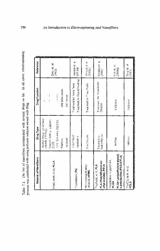
Tab
le 7
.1.
Th
e l i
st o
f na
nofi
bers
in
corp
orat
ed
wi t
h se
vera
l dr
ugs
so f
ar.
In a
ll c
ases
, el
ectr
ospi
nnin
gpr
oces
s w
as c
ondu
cted
wit
h us
ing
poly
mer
sol
utio
n m
ixed
wit
h dr
ug.
Ma t
e ria
l o
f N
a no
fib
e rs
Pol
yfL-
lact
ic a
cid)
, P
LL
A
Po
lyu
reth
an
e, P
U
Hyd
roxy
lpro
pyl m
ethy
lce
llulo
se,
HP
MC
Pol
yfla
ctic
aci
d),
PL
A
PL
A/P
oly
(eth
yle
ne
-co
-vi
nyl
ace
tate
), P
EV
A
Pol
y(la
ctid
e-co
-gly
colid
e),
PL
GA
PL
GA
/ p
oly
eth
yle
ne
gly
col)
-b
-po
ly(l
acti
de)
(P
EG
-b-P
LA
)
Pol
y(D
,L-l
actic
aci
d),
PD
LA
Dru
g T
yp
e
Tri
e th y
l b
en
zyl
am
mo
niu
mch
lorid
e (T
EB
AC
)
Sod
ium
do
decy
i su
lph
ate
(SD
S)
PP
O-P
EO
eth
er (
AE
01
0)
Rifa
mpi
n
Pac
litax
el
Itra
cona
zole
Ket
anse
rin
Itra
cona
zole
Tet
racy
clin
ehy
droc
hlon
de
Mef
oxi n
Mef
oxi n
Dru
g F
un
c tio
n
Ant
i-tu
berc
ulos
is
Ant
i-ca
ncer
Tre
atm
en
t fo
r Ti n
ea P
ed
is
Tre
atm
en
t fo
r W
ou
nd
Hea
ling
Tre
atm
en
t fo
r T
ine
a P
ed
is
Tre
atm
en
t fo
r P
erio
dont
alD
isea
se
Ant
ibio
tics
Ant
ibio
tics
Re f
e re n
c e
Zen
g e
t. a
l.(2
003)
Ve
r re
cke
t. a
l(2
003a
)
Ver
reck
et.
al
(200
3b)
Ken
awy
et. a
l(2
002)
Kim
et.
ai.
(200
4d)
Zon
g e
t al
(200
2)
286 An Introduction to Electrospinning and Nanofibers
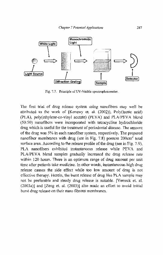
Chapter 7 Potential Applications 287
Fig. 7.7. Principle of UV-Visible spectrophotometer.
The first trial of drug release system using nanofibers may well beattributed to the work of [Kenawy et. al. (2002)]. Poly(lactic acid)(PLA), poly(ethylene-co-vinyl acetate) (PEVA) and PLA/PEVA blend(50:50) nanofibers were incorporated with tetracycline hydrochloridedrug which is useful for the treatment of periodontal disease. The amountof the drug was 5% in each nanofiber system, respectively. The preparednanofiber membranes with drug (see in Fig. 7.8) possess 200cm2 totalsurface area. According to the release profile of the drug (see in Fig. 7.9),PLA nanofibers exhibited instantaneous release while PEVA andPLA/PEVA blend samples gradually increased the drug release ratewithin 120 hours. There is an optimum range of drug amount per unittime after patients take medicine. In other words, instantaneous high drugrelease causes the side effect while too low amount of drug is noteffective therapy. Herein, the burst release of drug like PLA sample maynot be preferable and steady drug release is suitable. [Verreck et. al.(2003a)] and [Zeng et. al. (2003)] also made an effort to avoid initialburst drug release on their nano fibrous membranes.
288 An Introduction to Electrospinning and Nanofibers
Fig. 7.8. Poly(ethylene-co-vinyl acetate) (PEVA) nano fibrous membrane whichcontains tetracycline hydrochloride [Kenawy et. al. (2002)].
Fig. 7.9. Drug release profile of 1) Poly(ethylene-co-vinyl acetate) (PEVA), 2)Poly(lactic acid) (PLA) and PLA / PEVA (50:50) nano fibrous membranes [Kenawyet. al. (2002)].
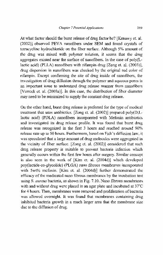
Chapter 7 Potential Applications 289
At what factor should the burst release of drug factor be? [Kenawy et. al.(2002)] observed PEVA nanofibers under SEM and found crystals oftetracycline hydrochloride on the fiber surface. Although 5% amount ofthe drug was mixed with polymer solution, it seems that the drugaggregates existed near the surface of nanofibers. In the case of poly(L-lactic acid) (PLLA) nanofibers with rifampin drug [Zeng et. al. (2003)],drug dispersion in nanofibers was checked by the original red color ofrifampin. Except confirming the site of drug inside of nanofibers, theinvestigation of drug diffusion through the polymer and aqueous pores isan important issue to understand drug release manner from nanofibers[Verreck et. al. (2003a)]. In this case, the distribution of fiber diametermay need to be minimized to supply the constant drug release.
On the other hand, burst drug release is preferred for the type of medicaltreatment that uses antibiotics. [Zong et. al. (2002)] prepared poly(D,L-lactic acid) (PDLA) nanofibers incorporated with Mefoxin antibioticsand investigated its drug release profile. It was found that burst drugrelease was recognized in the first 3 hours and reached around 90%release rate up to 50 hours. Furthermore, based on Fick's diffusion law, itwas speculated that a large amount of drug molecules were aggregated inthe vicinity of fiber surface. [Zong et. al. (2002)] considered that suchdrug release property is suitable to prevent bacteria infection whichgenerally occurs within the first few hours after surgery. Similar conceptis also seen in the work of [Kim et. al. (2004d)] which developedpoy(lactide-co-glycolide) (PLGA) nano fibrous membranes incorporatedwith 5wt% mefoxin. [Kim et. al. (2004d)] further demonstrated theefficacy of the medicated nano fibrous membranes by the incubation testusing S. aureus bacteria, as shown in Fig. 7.10. Nano fibrous membraneswith and without drug were placed in an agar plate and incubated at 37°Cfor 4 hours. Then, membranes were removed and proliferation of bacteriawas allowed overnight. It was found that membranes containing druginhibited bacteria growth in a much larger area that the membrane sizedue to the diffusion of drug.
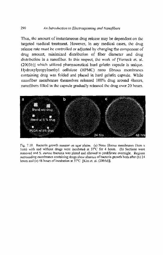
290 An Introduction to Electrospinning and Nanofibers
Thus, the amount of instantaneous drug release may be dependent on thetargeted medical treatment. However, in any medical cases, the drugrelease rate must be controlled or adjusted by changing the component ofdrug amount, minimized distribution of fiber diameter and drugdistribution in a nanofiber. In this respect, the work of [Verreck et. al.(2003b)] which utilized pharmaceutical hard gelatin capsule is unique.Hydroxylpropylmethyl cellulose (HPMC) nano fibrous membranescontaining drug was folded and placed in hard gelatin capsule. Whilenanofiber membranes themselves released 100% drug around 4hours,nanofibers filled in the capsule gradually released the drug over 20 hours.
Fig. 7.10. Bacteria growth manner on agar plates, (a) Nano fibrous membranes (lcm xlcm) with and without drugs were incubated at 37°C for 4 hours, (b) Sections wereremoved and S. aureus bacteria was plated and allowed to proliferate overnight. Regionssurrounding membranes containing drugs show absence of bacteria growth both after (b) 24hours and (c) 48 hours of incubation at 37°C [Kim et. al. (2004d)].

Chapter 7 Potential Applications 291
7.4. Tissue Scaffolds
Tissue scaffolds are utilized to repair the damaged human tissues.Seeded cells adhere and grow on tissue scaffolds immersed in thenutrient culture media and the scaffolds with cells are implanted at thehuman tissue defects. So far many different types of tissue scaffoldsmade of micron size material structure have been developed. However,the researchers realized that all of the human tissues such as bloodvessel, cartilage, bone, nerve and skin, consist of nano fibrous formsfrom biological viewpoint. This finding brought the researcher'sattention to nano structured scaffolds, and enhanced cell growth via suchscaffolds at the damaged tissues has been expected. Hence, we can seemuch potential of the utilization of electrospun polymer nanofibers torepair human tissues. This section introduces the readers about thebackground and utilization of electrospun polymer nanofibers in eachtargeted tissue.
Blood Vessel
Blood vessels perform a very important function of carrying andtransporting blood to and from the heart. As there are currently noacceptable synthetic prostheses or scaffolds for small-diameter bloodvessels, surgeons have to harvest the patient's own blood vessel for thetransplant. This procedure is not only time consuming, it may also lead tocomplications and significantly increases the recovery time for thepatient. It also restricts the number of patients that are suitable for thesurgery due to the limited vessels in the body appropriate for transplant.As a result, there have been many attempts to construct a viable bloodvessel substitute.
In order to construct blood vessel scaffold, it is important to understandthe basic structures of the natural blood vessel. The general structure of ablood vessel contains three layers, a tunica intima (innermost layer), atunica media (middle layer), and a tunica adventitia (outermost layer).The tunica intima consists of a lining of endothelial cells (ECs) and anunderlying layer of connective tissue with elastic fibers.
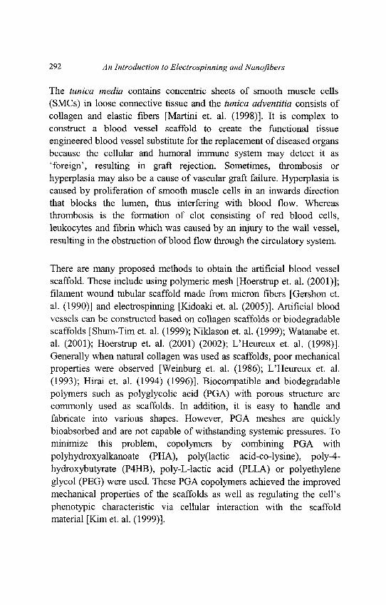
292 An Introduction to Electrospinning and Nanofibers
The tunica media contains concentric sheets of smooth muscle cells(SMCs) in loose connective tissue and the tunica adventitia consists ofcollagen and elastic fibers [Martini et. al. (1998)]. It is complex toconstruct a blood vessel scaffold to create the functional tissueengineered blood vessel substitute for the replacement of diseased organsbecause the cellular and humoral immune system may detect it as'foreign', resulting in graft rejection. Sometimes, thrombosis orhyperplasia may also be a cause of vascular graft failure. Hyperplasia iscaused by proliferation of smooth muscle cells in an inwards directionthat blocks the lumen, thus interfering with blood flow. Whereasthrombosis is the formation of clot consisting of red blood cells,leukocytes and fibrin which was caused by an injury to the wall vessel,resulting in the obstruction of blood flow through the circulatory system.
There are many proposed methods to obtain the artificial blood vesselscaffold. These include using polymeric mesh [Hoerstrup et. al. (2001)];filament wound tubular scaffold made from micron fibers [Gershon et.al. (1990)] and electrospinning [Kidoaki et. al. (2005)]. Artificial bloodvessels can be constructed based on collagen scaffolds or biodegradablescaffolds [Shum-Tim et. al. (1999); Niklason et. al. (1999); Watanabe et.al. (2001); Hoerstrup et. al. (2001) (2002); L'Heureux et. al. (1998)].Generally when natural collagen was used as scaffolds, poor mechanicalproperties were observed [Weinburg et. al. (1986); L'Heureux et. al.(1993); Hirai et. al. (1994) (1996)]. Biocompatible and biodegradablepolymers such as polyglycolic acid (PGA) with porous structure arecommonly used as scaffolds. In addition, it is easy to handle andfabricate into various shapes. However, PGA meshes are quicklybioabsorbed and are not capable of withstanding systemic pressures. Tominimize this problem, copolymers by combining PGA withpolyhydroxyalkanoate (PHA), poly(lactic acid-co-lysine), poly-4-hydroxybutyrate (P4HB), poly-L-lactic acid (PLLA) or polyethyleneglycol (PEG) were used. These PGA copolymers achieved the improvedmechanical properties of the scaffolds as well as regulating the cell'sphenotypic characteristic via cellular interaction with the scaffoldmaterial [Kim et. al. (1999)].
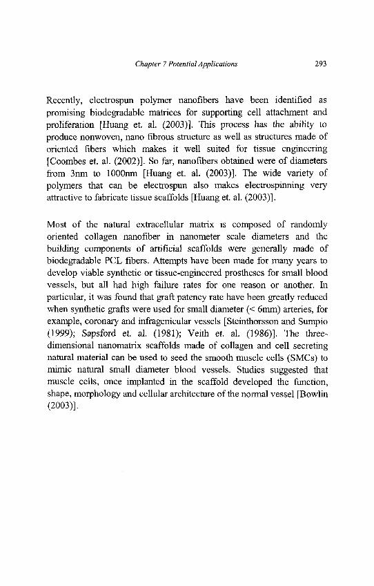
Chapter 7 Potential Applications 293
Recently, electrospun polymer nanofibers have been identified aspromising biodegradable matrices for supporting cell attachment andproliferation [Huang et. al. (2003)]. This process has the ability toproduce nonwoven, nano fibrous structure as well as structures made oforiented fibers which makes it well suited for tissue engineering[Coombes et. al. (2002)]. So far, nanofibers obtained were of diametersfrom 3nm to lOOOnm [Huang et. al. (2003)]. The wide variety ofpolymers that can be electrospun also makes electrospinning veryattractive to fabricate tissue scaffolds [Huang et. al. (2003)].
Most of the natural extracellular matrix is composed of randomlyoriented collagen nanofiber in nanometer scale diameters and thebuilding components of artificial scaffolds were generally made ofbiodegradable PCL fibers. Attempts have been made for many years todevelop viable synthetic or tissue-engineered prostheses for small bloodvessels, but all had high failure rates for one reason or another, hiparticular, it was found that graft patency rate have been greatly reducedwhen synthetic grafts were used for small diameter (< 6mm) arteries, forexample, coronary and infragenicular vessels [Steinthorsson and Sumpio(1999); Sapsford et. al. (1981); Veith et. al. (1986)]. The three-dimensional nanomatrix scaffolds made of collagen and cell secretingnatural material can be used to seed the smooth muscle cells (SMCs) tomimic natural small diameter blood vessels. Studies suggested thatmuscle cells, once implanted in the scaffold developed the function,shape, morphology and cellular architecture of the normal vessel [Bowlin(2003)].
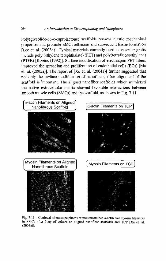
294 An Introduction to Electrospinning and Nanofibers
Poly(glycolide-co-e-caprolactone) scaffolds possess elastic mechanicalproperties and promote SMCs adhesion and subsequent tissue formation[Lee et. al. (2003d)]. Typical materials currently used as vascular graftsinclude poly (ethylene terephthalate) (PET) and poly(tetrafluoroethylene)(PTFE) [Robins (1992)]. Surface modification of electrospun PET fibersimproved the spreading and proliferation of endothelial cells (ECs) [Maet. al. (2005a)]. The report of [Xu et. al. (2004a)] further suggested thatnot only the surface modification of nanofibers, fiber alignment of thescaffold is important. The aligned nanofiber scaffolds which mimickedthe native extracellular matrix showed favorable interactions betweensmooth muscle cells (SMCs) and the scaffold, as shown in Fig. 7.11.
Fig. 7.11. Confocal microscope photos of immunostained a-actin and myosin filamentsin SMCs after lday of culture on aligned nanofiber scaffolds and TCP [Xu et al(2004a)].
Chapter 7 Potential Applications 295
The electrospinning method used to fabricate the scaffold is simple forthe mass production and have huge potential for the application in bloodvessel engineering. Various methods have been developed to support theseeding and growth of endothelial cells on polyurethane (PU) or otherbiomaterial surfaces through methods such as surface modifications byplasma treatment and photochemical grafting GRGD peptide on amodified PU surface or chitosan surface. The above mentioned surfacemodifications may be categorized as chemical or biological surfacemodifications to enhance endothelialization on biomaterial surfaces. Onthe other hand, modifications of physical properties of surfaces such asenhancing hydrophilic properties, changing porosity of materials andincreasing roughness of surface may also enhance endothelialization ofbiomaterials [Chung et. al. (2003); Xu et. al. (2004b)].
Endothelialization is a promising way to minimize hyperplasia asendothelial cells secrete bioactive substances that inhibit smooth musclecells from excessive proliferating. As the basement membrane consist oftype IV collagen and laminin nanofibers and has a similar structure asnon-woven polymer nanofibrous membranes, studies were conducted tofacilitate viability, attachment and phenotypic maintenance of humancoronary artery endothelial cells on poly(L-lactid-co-E-caprolactone)[P(LLA-CL)] copolymer nanofibers incorporated with collagen [He et.al. (2005a) (2005b)]. It was shown that collagen coating on nanofibersimproved viability and attachment of endothelial cells, as shown in Fig.7.12. Tensile properties of fabricated nanofibrous scaffolds wereequivalent to that of the human artery and were less stiff than acommonly used graft material, Dacron (PET). It was also found thatendothelial cells could be spread without serum and growth factors inculture medium [He et. al. (2005b)].
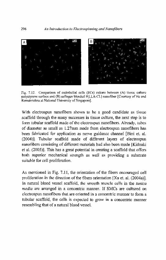
296 An Introduction to Electrospinning and Nanofibers
Fig. 7.12. Comparison of endothelial cells (ECs) culture between (A) tissue culturepolystyrene surface and (B) collagen blended P(LLA-CL) nanofiber [Courtesy of He andRamakrishna at National University of Singapore].
With electrospun nanofibers shown to be a good candidate as tissuescaffold through the many successes in tissue culture, the next step is toform tubular scaffold made of the electrospun nanofibers. Already, tubesof diameter as small as 1.27mm made from electrospun nanofibers hasbeen fabricated for application as nerve guidance channel [Bini et. al.(2004)]. Tubular scaffold made of different layers of electrospunnanofibers consisting of different materials had also been made [Kidoakiet al. (2005)]. This has a great potential in creating a scaffold that offersboth superior mechanical strength as well as providing a substratesuitable for cell proliferation.
As mentioned in Fig. 7.11, the orientation of the fibers encouraged cellproliferation in the direction of the fibers orientation [Xu et. al. (2004a)].In natural blood vessel scaffold, the smooth muscle cells in the tunicamedia are arranged in a concentric manner. If SMCs are cultured onelectrospun nanofibers that are oriented in a concentric manner to form atubular scaffold, the cells is expected to grow in a concentric mannerresembling that of a natural blood vessel.
Chapter 7 Potential Applications 297
Several methods have been proposed to control the orientation of theelectrospun nanofibers from the use of a rotating collector [Theron et. al.(2001); Boland et. al. (2001); Matthews et. al. (2002)] to controlling theelectric field during electrospinning [Li et. al. (2003b)]. The resultantmesh consisting of aligned electrospun nanofibers may then be rolledinto a tubular scaffold. By using both a rotating tube and controlling theelectric field, it is possible to align the electrospun nanofibers on thecircumference of the small-diameter tube which can then be extracted togive a tubular scaffold [Bornat (1987)]. The pattering of nanofiberdeposition is described in chapter 3 in details.
While this area remains a great challenge in the area of tissueengineering as many requirements need to be fulfilled, there is still agreat potential in constructing a viable blood vessel substitute for tissuetransplantations.
Cartilage
Cartilage is a dense connective tissue that is to a certain extent pliable,making it resilient. These characteristics are due to the nature of itsmatrix, which is rich in proteoglycans consisting of a core proteinattached by the repeating units of disaccharides termedglycosaminoglycans (GAGs). Hyaluronic acid (HA), chondroitin sulfateand keratin sulfate are the most abundant GAGs found in cartilage. Thematrix also has collagen fibers, but these are of a finer nature (CollagenType II vs. Collagen Type I) than the collagen fibers in most otherconnective tissues. The macromolecules are bound to the thin collagenfibers by electrostatic interactions and cross-linking glycoprotein. Thereare 3 types of cartilage: hyaline cartilage (most abundant type), elasticcartilage and fibro cartilage.
298 An Introduction to Electrospinning and Nanofibers
Articular cartilages are important in load-bearing and reducing friction ofthe articular surfaces. Due to the limited capacity of articular cartilage torepairitself, and cartilage defect resulting from aging, joint injury anddevelopmental disorders cause joint pain and loss of mobility [Li et. al.(2005b)], many attempts have been made to repair articular cartilagedefects, which include transplantations of various tissues or cells.[Hattori et. al. (2002)], for example, used an autologous culturedchondrocyte or autologous bone marrow mesenchymal celltransplantations in repairing the articular cartilage defects. Tissueengineering approach provides a cell based therapy to repair the defectand restore joint functions [Grad et. al. (2003)]. hi addition to that, manydifferent techniques have been developed to produce nanostructuredbiodegradable materials such as microspheres, foams and films. It hasbeen demonstrated that the molecular structure and morphology of PLA,PGA, PCL and their copolymers can play a major role in the degradationand mechanical properties of the final products [Lu et. al. (2001)].Modifications of physical properties of surfaces such as enhancinghydrophilic properties, changing porosity of materials and increasingroughness of surface may also enhance cellularization of biomaterials.Polymer scaffolds are primarily used for the delivery and retention ofchondrogenic cells in cartilage tissue engineering [Reinholz et. al.(2004)]. Many naturally derived and synthetic polymers are currentlyused as scaffolds for regeneration of articular cartilage and many othersare under development. Recent advances in stem cell biology haveshown that, mesenchymal stem cells can differentiate into cells ofmesenchymal tissues such as bone, cartilage, muscle, tendon, ligamentand fat and are expected to play an important role in the repair of skeletaldefects.
Chapter 7 Potential Applications 299
Electrospinning has provided a basis for the fabrication of uniquematrices and scaffolds for tissue engineering and a strong application inbiomedical engineering. The structural design of artificial matrices orscaffolds that mimic the supramolecular structure and biologicalfunctions of the extracellular matrix (ECM) is a key issue in tissueengineering and the development of artificial organs. In cartilage tissueengineering, chondrocytes and mesenchymal stem cells (MSC) arecommonly used for cartilage regeneration. PCL nano fibrous scaffoldsstructurally similar to ECM may represent promising structures for tissueengineering applications. Three dimensional nano fibrous scaffolds arecharacterized by high porosity with a wide distribution of pore diameter,high surface to volume ratio and morphological similarities to naturalcollagen fibrils. These nano fibrous scaffolds are readily fabricated inany shape and size as needed clinically and also provides soundmechanical stability to provide a carrier for MSC transplantation in tissueengineering cartilage repair. Many naturally derived and syntheticpolymers are currently used as scaffolds for regeneration of articularcartilage and many others are under development. Collagen, PLLA,PLGA and PCA were shown to be suitable as a scaffold for in vitrocartilage regeneration, as demonstrated by cell densities equivalent tothose found in natural tissues and by continued cellular production oftype II collagen [Grande et. al. (1997); Freed and Vunjak-Novakovic(1995)].
Bone
Bone is a connective tissue distinguished by the fact that its matrix ismineralized by calcium phosphate in the form of crystals very similar tohydroxyapatite (calcium phosphate mineral). The minerals are bothfound in the collagen fibers (Type I) which constitute about 95% of thematrix, and in the ground substance. Bone is both resilient and hard. Itsresilience is due to the organic matter (collagen), its hardness due to theinorganic minerals. Bone serves as a storage site for calcium andphosphate. There are two kinds of mature bone: compact bone (densebone/ cortical bone) and spongy bone (cancellous bone, trabecular boneand medullary bone).
300 An Introduction to Electrospinning and Nanofibers
Compact bone and spongy bone are found in specific locations. In longbones, most of the thickness of the diaphysis is made of compact bone,with a small amount of spongy bone facing the marrow cavity. The ends(epiphyses) of long bones, however, consist mostly of spongy bonecovered with a shell of compact bone. The flat bones of the skull have amiddle layer of spongy bone sandwiched between two relatively thicklayers of compact bone.
Developing natural or synthetic substances to replace the body's tissues,organs or functions is the goal of biomaterials research. In tissueengineering, synthetic compounds are used to augment patient's livingtissue. Tissue-engineered bone grafts have been used to fill defects inbone caused by clinical states or trauma, such as fractures with bone loss,bone infection, or bone tumors. A bone graft is a piece of bonetransplanted to another part of the skeleton where it is needed to improvefunction or strengthen the structure of the area. Sometimes a bone graft istaken from a cadaver, but usually it is harvested from the patient forwhich it will be used. Aside from blood, bone is the most frequentlytransplanted tissue in humans. Bone grafts are typically harvested fromthe patient's iliac crest (top of the hip bone), ribs, or fibula in the lowerleg. They may be used in plastic surgery to reconstruct a chin or in dentalsurgery to provide a bony bed for a dental implant. The application andsurgical site help determine how a bone graft performs, if it healsproperly and offers the same durability as the original tissue.
Autologous bone is the current gold standard graft material without therisk of transfer of disease for the treatment of skeletal defects andfracture repair. In contrast, the use of allogenic bone may transmitdiseases and cause an immune response, which can lead to high failurerate. One of the main goals in tissue engineering has been to developbiodegradable materials as bone graft substitutes for filling large bonedefects. These materials should maintain adequate mechanical strengthover critical phases of the tissue healing process and also should be
Chapter 7 Potential Applications 301
oesteoconductive. Furthermore, the proper degradation at a controlledrate is required to provide space for the formation of new bone.
Engineering living tissue for reconstructive surgery requires anappropriate cell source, optimal culture conditions and a biodegradablescaffold as the basic elements. While specialized cells remain animportant source, stem cells have emerged as a promising newalternative. Recent advances in stem cell biology have shown thatmesenchymal stem cells (MSC) can differentiate into cells ofmesenchymal tissues such as bone, cartilage, muscle, tendon, ligamentand fat and are expected to play an important role in the repair of skeletaldefects [Olivier et. al. (2004); Caplan (1991); Pittenger et. al. (1999)].Osteoblasts derived from MSC of neonatal rats were cultured on poly(DL-lactide-co-glycolide) foams and mineralizations as well as three-dimensional bone formation were observed [Terai et. al. (2002)]. Celladhesion is the most important aspects of cell interaction with abiomaterial because it is the prerequisite for further cellular activity suchas spreading, proliferation and differentiation. Initial osteoblast/materialinteractions may be conveniently characterized by four stages: (1)protein adsorption to the surface, (2) contact of rounded cells, (3)attachment of cell to the substrate, and (4) spreading of cells. Initial cellattachment is influenced by the original surface characteristics of thematerials [Leong et. al. (1985)]. In later phase of cell development,however, other factors such as polymer degradation products or bulkproperties may play a more crucial role.
Biodegradable polymers often have been combined with bioceramics toproduce materials for bone repair. Biodegradable polymers such as PGA,PLA and PLGA have found application as resorbable sutures[Beniceuicz and Hopper (1991)] bone fixation screws and plates, drugcarriers, and they have been widely investigated as bone graft substituteswith positive results [Holland et. al. (1986); Ishaug et. al. (1994)].
302 An Introduction to Electrospinning and Nanofibers
Polycaprolactone (PCL) has been investigated mainly for long-termimplants for drug release and support mineralized tissue formation andmay be a suitable candidate for the treatment of bone defects [Yoshimotoet. al. (2003)]. An improvement in the mechanical properties of PCL hasbeen achieved by co-polymerization with PLA, enabling its use fororthopedic applications, such as the repair of bone defects. There hasbeen widespread use of bioceramics such as hydroxyapatite (HA) andtricalciumphosphate (TCP) for bone regeneration applications and theirbiocompatibility is thought to be due to their structural similarity to themineral phase of bone. Biodegradable ceramics are used in dental andorthopedic surgery as fillers for bone defects and as coatings on metallicimplants to improve implant integration in host bone. Biodegradablepolymers have been used as binders for HA and TCP to overcome theproblems of brittleness and the difficulty of shaping hard ceramicmaterials to fit bone defects [Rizzi et. al. (2001)]. At the same time,bioceramic reinforcement of polymers has been shown to improvemechanical properties and osteoconductivity [Kikuchi et. al. (1997)].Biodegradable polymer/bioceramic composites are promising materialsfor bone graft replacement and this has been intensively investigated inthe last decade [Piattelli et. al. (1997)]. With this respect, PCL/CalciumCarbonate (CaCO3) composite nanofibers have been investigated aspossible bone substrates [Fujihara et. al. (2005)]. The surface of PCLnanofibers was covered by CaCO3 nano particles (see in Fig. 7.13) andosteoblast attachment was encouraged on composite nano fibrousmembrane in vitro.
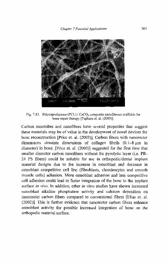
Chapter 7 Potential Applications 303
Fig. 7.13. Polycaprolactone (PCL) / CaCO3 composite nanofibrous scaffolds forbone repair therapy [Fujihara et. al. (2005)].
Carbon nanotubes and nanofibers have several properties that suggestthese materials may be of value in the development of novel devices forbone reconstruction [Price et. al. (2003)]. Carbon fibers with nanometerdimensions simulate dimensions of collagen fibrils (0.1-8 um indiameter) in bone. [Price et. al. (2003)] suggested for the first time thatsmaller diameter carbon nanofibers without the pyrolytic layer (i.e. PR-24 PS fibers) could be suitable for use in orthopedic/dental implantmaterial designs due to the increase in osteoblast and decrease inosteoblast competitive cell line (fibroblasts, chondrocytes and smoothmuscle cells) adhesion. More osteoblast adhesion and less competitivecell adhesion could lead to faster integration of the bone to the implantsurface in vivo. In addition, other in vitro studies have shown increasedosteoblast alkaline phosphatase activity and calcium deposition onnanometer carbon fibers compared to conventional fibers [Elias et. al.(2002)]. This is further evidence that nanometer carbon fibers enhanceosteoblast activity for possible increased integration of bone on theorthopedic material surface.
304 An Introduction to Electrospinning and Nanofibers
Nerve
Nerve tissue repair is a significant treatment concept in human healthcare as it directly impacts on the quality of life. It is known that aproperly synthesized extracellar matrix (ECM) is crucial in guidingneural outgrowth and may be relevant to the process of regeneration. TheECM of the nervous system consists of the collagen types I, II, III, IVand V, the noncollagenous glycoproteins and the glycosaminoglycans(GAGs) [Rutka et. al. (1988); Carbonetto (1984)]. From the biologicalpoint of view, a great variety of natural ECM components exist in fibrousform and structure. Examples include collagen, fibronectin and laminin.All of them are characterized by well organized hierarchical fibrousstructures ranging from nanometer to millimeter scale. From this, asuccessful regeneration of nerves calls for the development of fibrousstructure with fiber architecture for cell deposition and proliferation.
Electrospinning provides a straightforward way to fabricate fibrouspolymer scaffold for neural tissue engineering. The potential of nanofibrous porous scaffold is prepared by phase separation using poly(l-lactic acid) with a similar structure of natural ECM in nerve tissueengineering [Yang et. al. (2004a)]. In a recent study [Bini et. al. (2004)],nerve guidance channel was fabricated by electrospinning poly(L-lactide-co-glycolide) biodegradable polymer nanofibers onto a Teflonmandrel. The feasibility of in vivo nerve regeneration was investigatedthrough several of these conduits. The biological performance of theconduits was examined in the rat sciatic nerve model with a 10mm gaplength. After implantation of the nano fibrous nerve guidance conduit tothe right sciatic nerve of the rat, there was no inflammatory response.One month after implantation five out of eleven rats showed successfulnerve regeneration (see in Fig. 7.14). None of the implanted conduitsshowed tube breakage. The nano fibrous nerve guidance conduits wereflexible, permeable and showed no swelling.
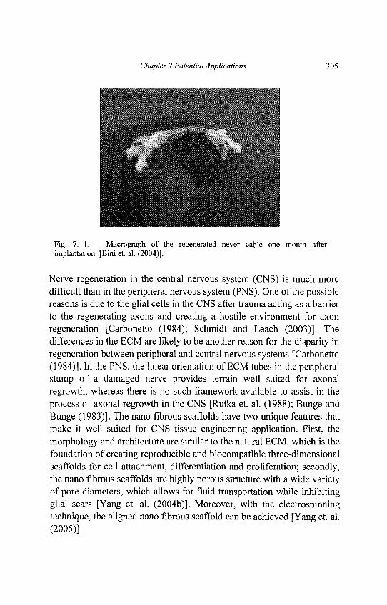
Chapter 7 Potential Applications 305
Fig. 7.14. Macrograph of the regenerated never cable one month afterimplantation. [Bini et. al. (2004)].
Nerve regeneration in the central nervous system (CNS) is much moredifficult than in the peripheral nervous system (PNS). One of the possiblereasons is due to the glial cells in the CNS after trauma acting as a barrierto the regenerating axons and creating a hostile environment for axonregeneration [Carbonetto (1984); Schmidt and Leach (2003)]. Thedifferences in the ECM are likely to be another reason for the disparity inregeneration between peripheral and central nervous systems [Carbonetto(1984)]. In the PNS, the linear orientation of ECM tubes in the peripheralstump of a damaged nerve provides terrain well suited for axonalregrowth, whereas there is no such framework available to assist in theprocess of axonal regrowth in the CNS [Rutka et. al. (1988); Bunge andBunge (1983)]. The nano fibrous scaffolds have two unique features thatmake it well suited for CNS tissue engineering application. First, themorphology and architecture are similar to the natural ECM, which is thefoundation of creating reproducible and biocompatible three-dimensionalscaffolds for cell attachment, differentiation and proliferation; secondly,the nano fibrous scaffolds are highly porous structure with a wide varietyof pore diameters, which allows for fluid transportation while inhibitingglial scars [Yang et. al. (2004b)]. Moreover, with the electrospinningtechnique, the aligned nano fibrous scaffold can be achieved [Yang et. al.(2005)].
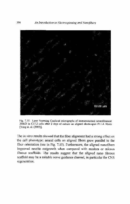
306 An Introduction to Electrospinning and Nanofibers
Fig. 7.15. Laser Scanning Confocal micrographs of immunostained neurofilament200kD in C17.2 cells after 2 days of culture on aligned electrospun PLLA fibers[Yang et. al. (2005)].
The in vitro results showed that the fiber alignment had a strong effect onthe cell phenotype: neural cells on aligned fibers grew parallel to thefiber orientation (see in Fig. 7.15). Furthermore, the aligned nanofibersimproved neurite outgrowth when compared with random or micronfibrous scaffolds. The results suggest that the aligned nano fibrousscaffold may be a suitable nerve guidance channel, in particular for CNSregeneration.
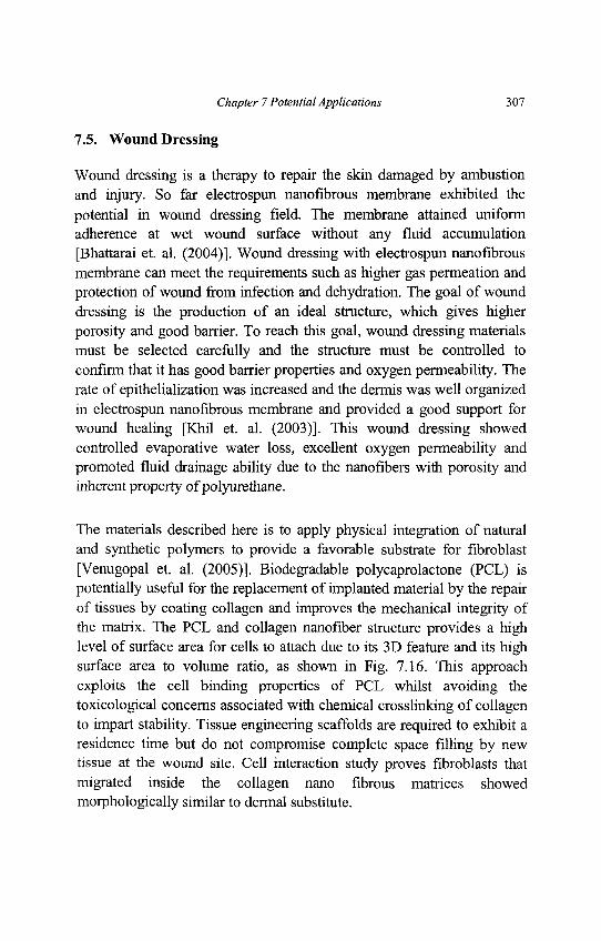
Chapter 7 Potential Applications 307
7.5. Wound Dressing
Wound dressing is a therapy to repair the skin damaged by ambustionand injury. So far electrospun nanofibrous membrane exhibited thepotential in wound dressing field. The membrane attained uniformadherence at wet wound surface without any fluid accumulation[Bhattarai et. al. (2004)]. Wound dressing with electrospun nanofibrousmembrane can meet the requirements such as higher gas permeation andprotection of wound from infection and dehydration. The goal of wounddressing is the production of an ideal structure, which gives higherporosity and good barrier. To reach this goal, wound dressing materialsmust be selected carefully and the structure must be controlled toconfirm that it has good barrier properties and oxygen permeability. Therate of epithelialization was increased and the dermis was well organizedin electrospun nanofibrous membrane and provided a good support forwound healing [Khil et. al. (2003)]. This wound dressing showedcontrolled evaporative water loss, excellent oxygen permeability andpromoted fluid drainage ability due to the nanofibers with porosity andinherent property of polyurethane.
The materials described here is to apply physical integration of naturaland synthetic polymers to provide a favorable substrate for fibroblast[Venugopal et. al. (2005)]. Biodegradable polycaprolactone (PCL) ispotentially useful for the replacement of implanted material by the repairof tissues by coating collagen and improves the mechanical integrity ofthe matrix. The PCL and collagen nanofiber structure provides a highlevel of surface area for cells to attach due to its 3D feature and its highsurface area to volume ratio, as shown in Fig. 7.16. This approachexploits the cell binding properties of PCL whilst avoiding thetoxicological concerns associated with chemical crosslinking of collagento impart stability. Tissue engineering scaffolds are required to exhibit aresidence time but do not compromise complete space filling by newtissue at the wound site. Cell interaction study proves fibroblasts thatmigrated inside the collagen nano fibrous matrices showedmorphologically similar to dermal substitute.
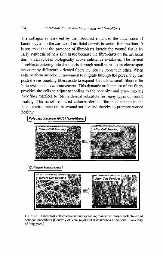
308 An Introduction to Electrospinning and Nanofibers
The collagen synthesized by the fibroblast enhanced the attachment ofkeratinocytes to the surface of artificial dermis in serum free medium. Itis assumed that the presence of fibroblasts invade the wound tissue byearly synthesis of new skin tissue because the fibroblasts on the artificialdermis can release biologically active substance cytokines. The dermalfibroblasts entering into the matrix through small pores in an electrospunstructure by differently oriented fibers lay loosely upon each other. Whencells perform amoeboid movement to migrate through the pores, they canpush the surrounding fibers aside to expand the hole as small fibers offerlittle resistance to cell movement. This dynamic architecture of the fibersprovides the cells to adjust according to the pore size and grow into thenanofiber matrices to form a dermal substitute for many types of woundhealing. The nanofiber based cultured dermal fibroblast maintains themoist environment on the wound surface and thereby to promote woundhealing.
Fig. 7.16. Fibroblast cell attachment and spreading manner on polycaprolactone andcollagen nanofibers [Courtesy of Venugopal and Ramakrishna at National Universityof Singapore ].
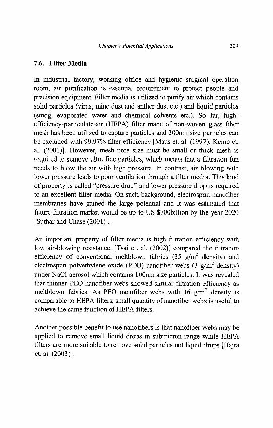
Chapter 7 Potential Applications 309
7.6. Filter Media
In industrial factory, working office and hygienic surgical operationroom, air purification is essential requirement to protect people andprecision equipment. Filter media is utilized to purify air which containssolid particles (virus, mine dust and anther dust etc.) and liquid particles(smog, evaporated water and chemical solvents etc.). So far, high-efficiency-particulate-air (HEPA) filter made of non-woven glass fibermesh has been utilized to capture particles and 300nm size particles canbe excluded with 99.97% filter efficiency [Maus et. al. (1997); Kemp et.al. (2001)]. However, mesh pore size must be small or thick mesh isrequired to remove ultra fine particles, which means that a filtration funneeds to blow the air with high pressure. In contrast, air blowing withlower pressure leads to poor ventilation through a filter media. This kindof property is called "pressure drop" and lower pressure drop is requiredto an excellent filter media. On such background, electrospun nanofibermembranes have gained the large potential and it was estimated thatfuture filtration market would be up to US $700billion by the year 2020[Suthar and Chase (2001)].
An important property of filter media is high filtration efficiency withlow air-blowing resistance. [Tsai et. al. (2002)] compared the filtrationefficiency of conventional meltblown fabrics (35 g/m2 density) andelectrospun polyethylene oxide (PEO) nanofiber webs (3 g/m2 density)under NaCl aerosol which contains lOOnm size particles. It was revealedthat thinner PEO nanofiber webs showed similar filtration efficiency asmeltblown fabrics. As PEO nanofiber webs with 16 g/m2 density iscomparable to HEPA filters, small quantity of nanofiber webs is useful toachieve the same function of HEPA filters.
Another possible benefit to use nanofibers is that nanofiber webs may beapplied to remove small liquid drops in submicron range while HEPAfilters are more suitable to remove solid particles not liquid drops [Hajraet. al. (2003)].
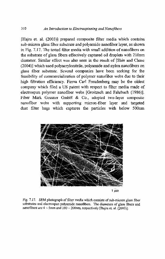
310 An Introduction to Electrospinning andNanofibers
[Hajra et. al. (2003)] prepared composite filter media which containssub-micron glass fiber substrate and polyamide nanofiber layer, as shownin Fig. 7.17. The tested filter media with small addition of nanofibers onthe substrate of glass fibers effectively captured oil droplets with 210nmdiameter. Similar effect was also seen in the result of [Shin and Chase(2004)] which used polyacrylonitrile, polyamide and nylon nanofibers onglass fiber substrate. Several companies have been seeking for thefeasibility of commercialization of polymer nanofiber webs due to theirhigh filtration efficiency. Firma Carl Freudenberg may be the oldestcompany which filed a US patent with respect to filter media made ofelectrospun polymer nanofiber webs [Groitzsch and Fahrbach (1986)].Fiber Mark Gessner GmbH & Co., adopted two-layer compositenanofiber webs with supporting micron-fiber layer and targeteddust filter bags which captures the particles with below 500nm
Fig. 7.17. SBM photograph of filter media which consists of sub-micron glass fibersubstrates and electrospun polyamide nanofibers. The diameters of glass fibers andnanofibers are 4 ~ 5mm and 100 ~ 200nm, respectively [Hajra et. al. (2003)].

Chapter 7 Potential Applications 311
diameter size [Emig et. al. (2002)]. Donaldson Company, USA hasalready commercialized nanofiber filter media consisted of 10|om sizecellulose fibers and 250nm size nanofibers, so called Ultra-Web® [Grafeand Graham (2003)]. In their trial, ISO Fine test which is commonly usedfor the evaluation of engine air cleaner was adopted. The test utilizedparticles in the size range of 0.7 ~ 70um and investigated how much dustwas captured by a filter media. It was found that micron-size cellulosefilter media indicated 68% sub-micron dust reduction while Ultra-Web®indicated 92% sub-micron dust reduction.
7.7. Chemical and Biological Protective Clothing
Background
These days, the worldwide threat of chemical and biological agents byhostile military and terrorist groups has been growing. There is a graveconcern in the development of reliable and stronger mechanisms ofdefense. Upholding the motto of "prevention is better than cure" is veryessential in the field of national security, where even the smallestcompromise cannot be made as it would lead to disastrous effects notonly to an individual but to the community and more so to the country asa whole. Hence attention is drawn to develop protective systems to fightthese chemical and biological weapons of mass destruction. With allthese advancements in artillery, soldier survivability has considerablyreduced. Chemical and biological weapons can be used across a widespectrum of warfare, from acts of assassination and small-scale terrorismto various tactical and operational situations, both defensive andoffensive, including strategic population attacks. The technical andeconomic barriers to development and weaponization have decreased.
The chemical agents can be divided into three major categories, nerveagents, blister agents/ vesicants and blood agents.The vesicants include:
312 An Introduction to Electrospinning and Nanofibers
HD - sulfur mustard (Yperite)HN - nitrogen mustardL - lewisite (arsenical vesicants may be used in a mixture with HD)CX - phosgene (properties and effects are very different from othervesicants)
HD and HN are the most feared mustard vesicants historically, becauseof their chemical stability, their persistency in the field, the insidiouscharacter of their effects by attacking skin as well as eyes and respiratorytract, and because no effective therapy is yet available for counteringtheir effects. Hence individual protection becomes mandatory tosafeguard from exposure and for these reasons, we would keep ourattention on prevention of the mustard gases only.
Nerve Agents
As their name suggests, nerve agents (OP compounds) attack the nervoussystem of the human body. All such agents function the same way: byinterrupting the breakdown of the neurotransmitters that signal musclesto contract, preventing them from relaxing. Initial symptoms followingexposure to sarin (and other nerve agents) are a runny nose, tightness inthe chest and dilation of the pupils. The effects of nerve agents are verylong lasting and cumulative (increased successive exposures), andsurvivors of nerve agent poisoning almost invariably suffer chronicneurological damage. Some of the nerve agents include the volatile Gtype and the non-volatile V type. Some of the chemicals known to havebeen manufactured for this purpose include Sarin, Soman, Tabun andVX.
Chapter 7 Potential Applications 313
Blood Agents
The most important route of poisoning is through inhalation. Bothgaseous and liquid hydrogen cyanide, as well as cyanide salts in solution,can also be taken up through the skin. Its high volatility probably makeshydrogen cyanide difficult to use in warfare since there are problems inachieving sufficiently high concentrations outdoors. On the other hand,the concentration of hydrogen cyanide may rapidly reach lethal levels ifit is released in confined spaces. The most important toxic effect of bloodagent is by inhibiting the metal-containing enzymes. One such enzyme iscytochromoxidase, containing iron. This enzyme system is responsiblefor the energy-providing processes in the cell where oxygen is utilized,i.e., cell respiration. When cell respiration ceases, it is no longer possibleto maintain normal cell functions, which may lead to cell mortality.Symptoms of poisoning vary and depend on, for example, route ofpoisoning, total dose and the exposure time. If blood agent has beeninhaled, the initial symptoms are restlessness and increased respiratoryrate. Other early symptoms are giddiness, headache, palpitations andrespiratory difficulty. These are later followed by vomiting, convulsions,respiratory failure and unconsciousness. If the poisoning occurs rapidly,e.g., as a result of extremely high concentrations in the air, there is notime for symptoms to develop and exposed persons may then suddenlycollapse and die.
Bio-warfare Agents
Biological pathogens released intentionally or accidentally, or naturallyoccurring, can result in disease or death. Human exposure to these agentsmay occur through inhalation, skin (cutaneous) exposure, or ingestion ofcontaminated food or water. Following exposure, physical symptomsmay be delayed and sometimes confused with naturally occurringillnesses. Biological warfare agents may persist in the environment andcause problems some time after their release.
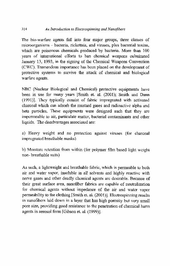
314 An Introduction to Electrospinning and Nanofibers
The bio-warfare agents fall into four major groups, three classes ofmicroorganisms - bacteria, rickettsia, and viruses, plus bacterial toxins,which are poisonous chemicals produced by bacteria. More than 100years of international efforts to ban chemical weapons culminatedJanuary 13, 1993, in the signing of the Chemical Weapons Convention(CWC). Tremendous importance has been placed on the development ofprotective systems to survive the attack of chemical and biologicalwarfare agents.
NBC (Nuclear Biological and Chemical) protective equipments havebeen in use for many years [Smith et. al. (2001); Smith and Dann(1991)]. They typically consist of fabric impregnated with activatedcharcoal which can adsorb the mustard gases and radioactive alpha andbeta particles. These equipments were designed such that they areimpermeable to air, particulate matter, bacterial contaminants and otherliquids. The disadvantages associated are:
a) Heavy weight and no protection against viruses (for charcoalimpregnated breathable masks)
b) Moisture retention from within (for polymer film based light weightnon- breathable suits)
As such, a lightweight and breathable fabric, which is permeable to bothair and water vapor, insoluble in all solvents and highly reactive withnerve gases and other deadly chemical agents are desirable. Because oftheir great surface area, nanofiber fabrics are capable of neutralizationfor chemical agents without impedance of the air and water vaporpermeability to the clothing [Smith et. al. (2001)]. Electrospinning resultsin nanofibers laid down in a layer that has high porosity but very smallpore size, providing good resistance to the penetration of chemical harmagents in aerosol form [Gibson et. al. (1999)].
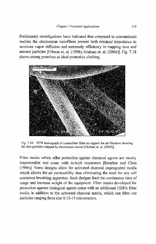
Chapter 7 Potential Applications 315
Preliminary investigations have indicated that compared to conventionaltextiles the electrospun nanofibers present both minimal impedance tomoisture vapor diffusion and extremely efficiency in trapping dust andaerosol particles [Gibson et. al. (1998); Graham et. al. (2004)]. Fig. 7.18shows strong promises as ideal protective clothing.
Fig. 7.18. SEM micrograph of a nanofiber filter on support for air filtration showingthe dust particles trapped by electrostatic action [Graham et. al. (2004)].
Filter masks which offer protection against chemical agents are mostlyimpermeable and come with in-built respirators [Reneker and Chun(1996)]. Some designs allow for activated charcoal impregnated mediawhich allows for air permeability thus eliminating the need for any selfcontained breathing apparatus. Such designs limit the continuous time ofusage and increase weight of the equipment. Filter masks developed forprotection against biological agents come with an additional HEPA filtermedia in addition to the activated charcoal media, which can filter outparticles ranging from size 0.13-15 micrometers.
316 An Introduction to Electrospinning and Nanofibers
Such types are referred to as M15, M40, etc. The M17 and M40 serieschemical-biological mask, when properly fitted and worn with the hood,protects against field concentrations of all known chemical andbiological agents in vapor or aerosol form, but fails to protect when theair has a low-oxygen content, such as in tunnels or caves, or when the airhas a high level of smoke mixtures. Nanofibers have an excellentpotential to be used in the air as well as particulate filtration. Thesenanofibers, fabricated by electrospinning have a very large surface areaand there by could be used as lining material for the face mask canisterswherein they aid in the capture and adsorption of the toxic chemicals andact as a barrier to the biological warfare agents. It was also shown thatthose with smaller diameter of fibers had better filtration efficiencies andcould be fabricated in smaller thicknesses, as shown in Fig. 7.19[Graham et. al. (2004)].
The Institute for Soldier Nanotechnologies (ISN) is an interdepartmentalresearch center at Massachusetts Institute of Technology (MIT), USA.Established in 2002 by a five-year, $50 million contract from the U.S.Army, the ISN's research mission is to use nanotechnology todramatically improve the survival rate of the soldiers. The ultimate goalis to create a 21st century battle suit that combines light weight high-techcapabilities with comfort. Nanotechnology fits into this vision in twoimportant ways. First, it offers the potential for miniaturization, a keypart of reducing the weight. Today's hefty radio worn on a harness mightbe reduced to a button-sized tab on the collar. A waterproof ponchocould be replaced by a permanent nano-thin coating applied toeverything the soldier carries.
Secondly, because nanotechnology operates at length scales wherebyclassical macroscopic physics no longer applies, it offers engineers thepotential for creating unprecedented new material properties and devices.As such, nanotechnology can solve problems that scientists have beenstruggling with for decades.
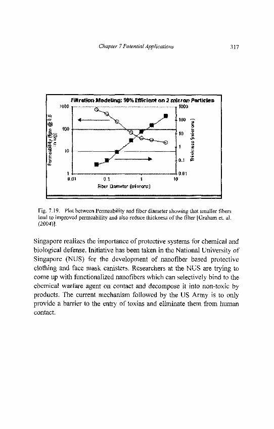
Chapter 7 Potential Applications 317
Fig. 7.19. Plot between Permeability and fiber diameter showing that smaller fiberslead to improved permeability and also reduce thickness of the filter [Graham et. al.(2004)].
Singapore realizes the importance of protective systems for chemical andbiological defense. Initiative has been taken in the National University ofSingapore (NUS) for the development of nanofiber based protectiveclothing and face mask canisters. Researchers at the NUS are trying tocome up with functionalized nanofibers which can selectively bind to thechemical warfare agent on contact and decompose it into non-toxic byproducts. The current mechanism followed by the US Army is to onlyprovide a barrier to the entry of toxins and eliminate them from humancontact.
318 An Introduction to Electrospinning and Nanoflbers
To encounter the above mentioned constraints, it is desired that the filtermedia's material in the face mask is selectively permeable. This ispossible by adopting polymer nanoflbers which are not only selectivelypermeable but are also very light weight. The proposed nanofiber mediacomprises of two distinct groups of fibers, one of which has the capacityto capture and decompose mustard gases and the other set of fibers isable to oxidize and deactivate nerve agents (organ phosphoruscompounds). Together the mesh has an average pore size of less than 500nm; this blocks the entry of bacterial spores of Bacillus Subtilis andBacillus Anthracis. High surface area and light weights are the chiefproperties of the nanoflbers which come into play to yield the increaseddecomposition efficiency. High surface area helps in the effectivebinding and deactivation of chemical and biological agents of target andthe light weight is due to the increased permeability of these nanofiberwebs which eliminate the need for external respirators. The proposedfilter media made up of polymer nanofibers would have sufficiently highporosity and thus would be able to avoid the issues from low oxygenpermeability.
Beneficial Features and Potential Impact to Defense and Security
1. Selective capture and decomposition of chemical warfare agents(Mustard and Nerve gases)
2. Removal of biological warfare agents by size separation (bacterialagents such as Bacillus Subtilis, Bacillus Anthracis)
3. Indication of contaminant levels
4. Submicron particulate filtration capability
5. Extended service lifetime of the material
6. Environmentally friendly and easy disposal
7. Cost-Effective
Chapter 7 Potential Applications 319
Hostile use of chemical and biological warfare agents is a serious threatto the men in the battlefield. This threat is amplified with the ease ofavailability and concealment of these agents. Hence, providing thesoldiers with physical protection and other means of surviving thesethreats is paramount. This project focuses on developing nano materialstechnology that can provide significant enhancement to chemical andbiological defense. Nano materials in the form of polymer nanofiberswith appropriate functionalization represent a breakthrough technologythat provides a means of making systems more practical and affordablefor individual protective equipments.
Presently, activated carbon-based permeable media systems such as theUS Joint Service Lightweight Integrated Suit Technology (JSLIST)[Smith et. al. (2001); Smith and Dunn (1991)] chemical protective overgarment can effectively stop the chemical agent vapor challenge, but at acost of heat stress, weight, and bulk. The development of lightweight andselectively permeable, breathable fabrics and filter media would be idealand very much in conjunction with the Defense Technology Objective(DTO) "Advanced Lightweight CB Protection".
The uses of polymer nanofibers not only help in weight reduction butalso help to increase the effective or available surface area forfunctionalization. These fibers have an estimated available surface ofabout 10-20m2/g compared to the 4m2/g for activated carbon adsorbentbased media [Smith and Dunn (1991)]. Increase in surface area impliesgreater adsorption (and enhanced decomposition) of chemical andbiological warfare agents and extended life of the media.
320 An Introduction to Electrospinning andNanofibers
7.8. Energy and Electrical Application
Background
In this century China, which has one of the largest populations in theworld, has been rapidly developing their industry and economy.Subsequently, the demand of energy consumption in China has beenincreasing every year. However, it is reported that estimated reserveamounts of oil and natural gas in the world are 41 years and 67 years,respectively [Source: Agency for Natural Resources and Energy, Japan,2005]. Furthermore, the readers may be reminded that the KyotoProtocol, a legally binding international agreement to reduce the amountof generated CO2, was concluded in 1997 [Source: Agency for NaturalResources and Energy, Japan, 2005]. A number of countries, especiallydeveloped countries such as G7, struggle to reduce the CO2 amountwhich is related to the improvement of efficient energy generatingequipment. Hence, it is considered that the clean energy generationsystem is an urgent requirement to address Kyoto Protocol. Table 7.2shows the typical clean energy systems without CO2 production so far,i.e., wind generator, solar power generator, hydrogen battery andpolymer battery. As described in the table, each system has advantagesand disadvantages. For wind generator, although the power generatingefficiency is good with low cost, the amount of generated power isgreatly influenced by the weather condition. Solar power energy utilizessilicon base photovoltaic semiconductors which convert light energy toelectricity.
Table 7.2. Advantage and disadvantage of typical clean energy.
Type of Clean Energy Advantage Disadvantage
. „ Eternal power generation Non-constant power generation, Noisewind venerator L Q W COS( G o Q d p o w e r g e n e r a t i o n Landscape problem
Solar Power Generator Eternal power generation Low energy density,soiar rower feneraior N o n . s i z e d e p e n d e n t P o w e r Efficiency Non-constant power generation
u j „„ Good Power Efficiency, Explosible gas, Gas storage problem,Hydrogen Battery Low-waste, Low-noise High cost
Polymer Battery Ugh, weigh,, Small geometry [IZTS"^^^"9
Chapter 7 Potential Applications 321
However, this system is also influenced by the weather condition andenergy generation level per density (energy density) still needs to beimproved. Hydrogen battery has been utilized in the power source ofhybrid-engine-cars and the technology of hydrogen battery may beestablished in near future although the storage cost of hydrogen is stillcostly.
Polymer Battery
With respect to polymer batteries, conductive polymers such aspolyvinylidenefluoride (PVdF) [Periasamy et. al. (1999); Singh andSekhon (2004); Sekhon and Singh (2004); Cheng et. al. (2005)],polyacrylonitrile (PAN) [Nicotera et. al. (2004); Kim et. al. (2001);Sekhon et. al. (2000)], poly(vinyl chloride) (PVC) [Su et. al. (1998)] andpoly(methyl methacrylate) (PMMA) [Kim and Oh (2002); Hashmi et. al.(2005)] have been utilized as gel condition with electrolyte solution. Asgeometry of polymer batteries can be compactly packed into a smallpackage, the targeted field of polymer batteries is mobile and notebookPC batteries. In this field, usage of electrospun polymer fibers has beenexpected because of pore structure and sub-micron to nano level sizenetwork of fibers. A pore structure of nano fibrous membrane leads tohigh electrolyte uptake while large surface area of nanofiber networkcontributes to excellent ion conductivity [Choi et. al. (2004e)]. [Choi et.al. (2003b)] also pointed out that conventional polymer gel electrolytesneed to address the handling difficulty for high-speed manufacturing oflithium polymer batteries. Hence, a few research groups have beenworking on the design of new polymer batteries using conductivepolymer nanofibers [Choi et. al. (2003b) (2004e); Choi et. al. (2004b);Honget. al. (2005)].
The important properties of polymer nanofiber batteries are (1) IonConductivity, (2) Interfacial Resistance and (3) ElectrochemicalStability. The detailed discussion of each is described as follows.
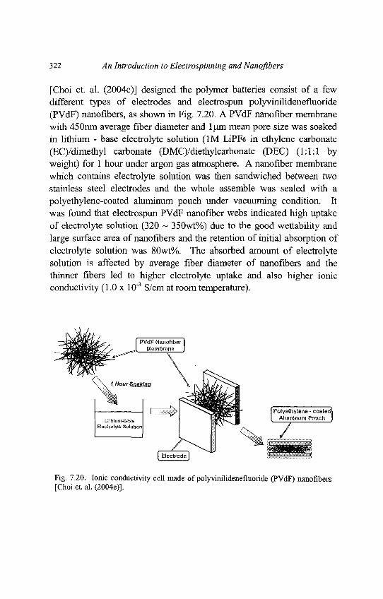
322 An Introduction to Electrospinning and Nanofibers
[Choi et. al. (2004e)] designed the polymer batteries consist of a fewdifferent types of electrodes and electrospun polyvinilidenefluoride(PVdF) nanofibers, as shown in Fig. 7.20. A PVdF nanofiber membranewith 450nm average fiber diameter and l(jm mean pore size was soakedin lithium - base electrolyte solution (1M LiPF6 in ethylene carbonate(EC)/dimethyl carbonate (DMC)/diethylcarbonate (DEC) (1:1:1 byweight) for 1 hour under argon gas atmosphere. A nanofiber membranewhich contains electrolyte solution was then sandwiched between twostainless steel electrodes and the whole assemble was sealed with apolyethylene-coated aluminum pouch under vacuuming condition. Itwas found that electrospun PVdF nanofiber webs indicated high uptakeof electrolyte solution (320 ~ 35Owt%) due to the good wettability andlarge surface area of nanofibers and the retention of initial absorption ofelectrolyte solution was 80wt%. The absorbed amount of electrolytesolution is affected by average fiber diameter of nanofibers and thethinner fibers led to higher electrolyte uptake and also higher ionicconductivity (1.0 x 10"3 S/cm at room temperature).
Fig. 7.20. Ionic conductivity cell made of polyvinilidenefluoride (PVdF) nanofibers[Choietal. (2004e)].
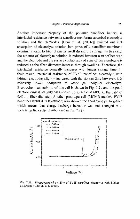
Chapter 7 Potential Applications 323
Another important property of the polymer nanofiber battery isinterfacial resistance between a nanofiber membrane absorbed electrolytesolution and the electrodes. [Choi et. al. (2004e)] pointed out thatabsorption of electrolyte solution into pores of a nanofiber membraneeventually leads to fiber diameter swell during the storage. In this case,the amount of electrolyte solution is reduced between a nanofiber weband the electrode and the surface contact area of a nanofiber membrane isreduced as the fiber diameter increase through swelling. Therefore, theinterfacial resistance generally increases with longer storage time. Intheir result, interfacial resistance of PVdF nanofiber electrolyte withlithium electrodes slightly increased with the storage time however, it isrelatively lower compared to other gel polymer electrolyte.Electrochemical stability of this cell is shown in Fig. 7.21 and the goodelectrochemical stability was shown up to 4.3V at 60°C in the case of0.45urn fiber diameter. Another prototype cell (MCMB anode/a PVdFnanofiber web/LiCoO2 cathode) also showed the good cycle performancewhich means that charge-discharge behavior was not changed withincreasing the cyclic number (see in Fig. 7.22).
Fig. 7.21. Electrochemical stability of PVdF nanofiber electrolyte with lithiumelectrodes [Choi et. al. (2004e)].
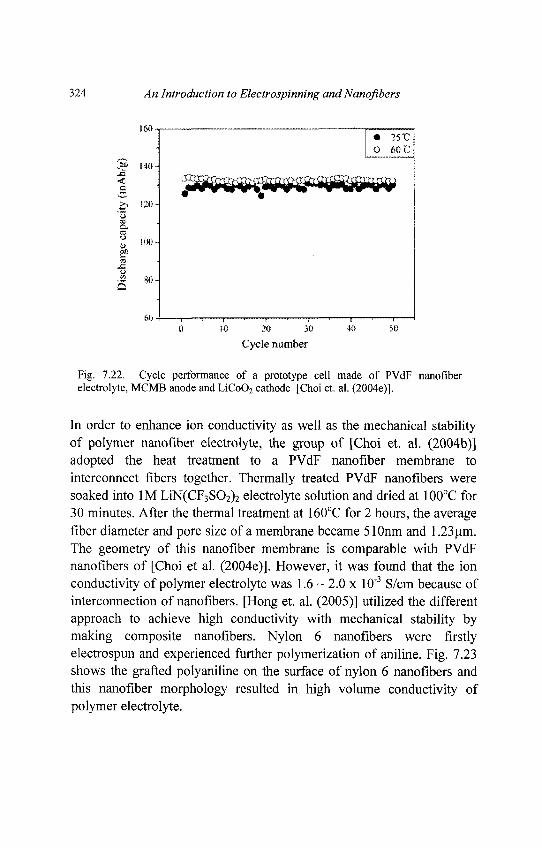
324 An Introduction to Electrospinning and Nanofibers
Fig. 7.22. Cycle performance of a prototype cell made of PVdF nanofiberelectrolyte, MCMB anode and LiCoO2 cathode [Choi et. al. (2004e)].
In order to enhance ion conductivity as well as the mechanical stabilityof polymer nanofiber electrolyte, the group of [Choi et. al. (2004b)]adopted the heat treatment to a PVdF nanofiber membrane tointerconnect fibers together. Thermally treated PVdF nanofibers weresoaked into 1M LiN(CF3SO2)2 electrolyte solution and dried at 100°C for30 minutes. After the thermal treatment at 160°C for 2 hours, the averagefiber diameter and pore size of a membrane became 510nm and 1.23 urn.The geometry of this nanofiber membrane is comparable with PVdFnanofibers of [Choi et al. (2004e)]. However, it was found that the ionconductivity of polymer electrolyte was 1.6 ~ 2.0 x 10"3 S/cm because ofinterconnection of nanofibers. [Hong et. al. (2005)] utilized the differentapproach to achieve high conductivity with mechanical stability bymaking composite nanofibers. Nylon 6 nanofibers were firstlyelectrospun and experienced further polymerization of aniline. Fig. 7.23shows the grafted polyaniline on the surface of nylon 6 nanofibers andthis nanofiber morphology resulted in high volume conductivity ofpolymer electrolyte.
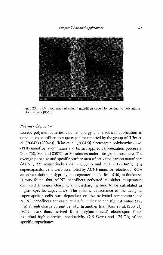
Chapter 7 Potential Applications 325
Fig. 7.23. SEM photograph of nylon 6 nanofibers coated by conductive polyaniline[Hong et. al. (2005)].
Polymer Capacitor
Except polymer batteries, another energy and electrical application ofconductive nanofibers is supercapacitor reported by the group of [Kim et.al. (2004b) (2004c)]. [Kim et. al. (2004b)] electrospun polybenzimidazol(PBI) nanofiber membranes and further applied carbonization process at700, 750, 800 and 850°C for 30 minutes under nitrogen atmosphere. Theaverage pore size and specific surface area of activated carbon nanofibers(ACNF) are respectively 0.64 ~ 0.66nm and 500 ~ 1220m2/g. Thesupercapacitor cells were assembled by ACNF nanofiber electrode, KOHaqueous solution, polypropylene separator andNi foil of 50um thickness.It was found that ACNF nanofibers activated at higher temperatureexhibited a longer charging and discharging time to be calculated ashigher specific capacitance. The specific capacitance of the designedsupercapcitor cells was dependent on the activated temperature andACNF nanofibers activated at 850°C indicated the highest value (178F/g) at high charge current density. In another trial [Kim et. al. (2004c)],ACNF nanofibers derived from poly(amic acid) electrospun fibersexhibited high electrical conductivity (2.5 S/cm) and 175 F/g of thespecific capacitance.
326 An Introduction to Electrospinning and Nanofibers
7.9. Sensors
The role of sensors is to transform physical or chemical responses into anelectrical signal based on the targeted application. So far electrospunpolymer nanofibers have been investigated as gas sensors, chemicalsensors, optical sensors and biosensors. It is considered that highsensitive sensors can be assembled by nanofibers which possess highsurface to volume ratio. Except sensitivity of sensors, quick responsetime with a targeted material is also expected to nanofiber sensors. Somecases replace the interfacial sensing material of conventional sensorswith nano fibrous membranes. The principle of nanofiber sensors is toutilize the chemical or physical reaction between a targeted material anda sensing material. Furthermore, the sensors convert the result of thosechemical or physical phenomena to the electrical output and finallyquantitative measurement of the detected materials is conducted. Here,electrospun polymer nanofibers which aimed at gas sensors, chemicalsensors, optical sensors and biosensors will be introduced in details.
Gas Sensors
Sensing toxic gases, such as carbon monoxide (CO), nitrogen dioxide(NO2) and ammonia (NH3) is a very serious issue to protect people in theresidence, office and industrial factory. For example, CO is generated bythe result of non-perfect burning of oil. In winter season, we occasionallysee gas poisoned victims which wrongly used gas stoves. For NH3 gas, itis ruled in UK that the exposure limit is 25ppm over 8 hours and 35ppmover 10 minutes [Christie et. al. (2003)]. As mentioned in introduction,for the soldier's protection from terrorist gas attacks, excellent alertsystem is necessary. Thus, the demand of high sensitive gas sensors hasincreased. For NH3 gas detection, we can see four examples of the usageof electrospun polymer nanofibers.
[Ding et. al. (2004a)] considered to use quartz crystal microbalances(QCM) sensors with electrospun nanofibers. It is acknowledged thatQCM sensors are widely used to detect the mass change in the presenceof coating material which reacts with the target gas.
Chapter 7 Potential Applications 327
Although a number of materials have been used as the coating materialof QCM sensors, [Ding et. al. (2004a)] applied nano fibrous membranefor the coating of QCM sensors. Poly(acrylic acid) (PAA) was chosen fornano fibrous membrane since carboxyl groups of PAA react withammonia. However, as electrospun PAA nano fibrous membranes couldnot be dried well due to the strong bonding between carboxyl groups andwater molecules, poly(vinyl alcohol) (PVA) was mixed with PAAsolution and then electrospinning process was conducted. It was shownthat sensitivity of QCM sensors coated with PVA-PAA nano fibrousmembrane at 50 ppm level of NH3 increased with increasing PAAamount. More importantly, QCM sensors coated with nanofibersdemonstrated higher gas sensitivity as compared to the sensors coatedwith PAA-poly(allylamine hydrochloride) (PAH) film. It was revealedthat large surface area of nano fibrous membrane contributed to highsensitivity to the gas. Ding et al. (2004b) further tried to improve thesensitivity of QCM sensors at lower concentration of NH3. At this time,higher molecular weight of PAA was prepared to make nanofibers anddry process of deposited PAA nanofibers became easier. Hence, the purePAA nano fibrous membrane could be applied to QCM sensors. As aresult, sensitivity of QCM sensors was improved up to 130ppb level ofNH3.
Conducting polymer nanowires also have the potential to detect NH3 gas[Liu et. al. (2004)]. [Liu et. al. (2004)] noticed the NH3 gas reactivity ofpolyaniline (PANI). PANI exhibits the character like p-typesemiconductor. It means NH3 gas supplies electrons to PANI whichresults in the reduction of charge-carrier concentration on a polymerchain and consequently conductivity of PANI decreases. Because of thisunique property, electrospun PANI/poly(ethylene oxide) (PEO)nanowires deposited on gold electrodes exhibited current change at0.5ppm level of NH3 gas. [Gouma et. al. (2003)] also utilized the changeof electrical property of metal oxides under gas exposure. The behindmechanism is that metal oxides possess the property of n-typesemiconductor which means electrical resistance of metal oxidesincreases with increasing gas existence.
328 An Introduction to Electrospinning and Nanofibers
Molybdenum oxide (MoO3)-PEO nano fibrous membranes wereelectrospun using sol-gel technique. Through sintering process, thedeposited membranes finally contained nanowires of lOOnm length and5-20nm width and MnO3 nano particle aggregates. Rapid change ofelectrical resistance of nanostructured metal oxides was recognized atlOOppm level of NH3 gas.
Chemical Sensors
The role of chemical sensors is to detect certain chemical component or achange of pH (potential of hydrogen) in a material system. [Kwoun et. al.(2000)] modified the conventional piezoelectric sensors, so calledThickness Shear Mode (TSM) sensors using electrospun nano fibrousmembrane. Poly-lactic acid-co-glycolic acid (PLAGA) nanofibers weredeposited on a sensing interface of TSM sensors and characterizationunder different liquid loading. [Kwoun et. al. (2000)] utilized the uniqueproperty of PLAGA which means that PLAGA polymer exhibitsmoderate hydrophobic properties against water while moderatehydrophilic properties against propanol. The response of TSM sensorscoated with PLAGA nanofibers definitely indicated different manner inthe water and propanol and the concept of sensors is very useful to detectcertain chemical component. [Kwoun et. al. (2001)] further investigatedthe property of TSM sensors coated with PLAGA nanofibers anddemonstrated that the sensor is useful to detect benzene gas.
Optical Sensors
Optical sensors utilize the fluorescence quenching of the sensing materialagainst the targeted chemical molecules. [Lee et. al. (2002b)] synthesizedthe florescent monomer and further polymerized with methacrylatemonomer. As shown in Fig. 7.24(a), the synthesized polymer possesseshigh photo sensitive pyrene.
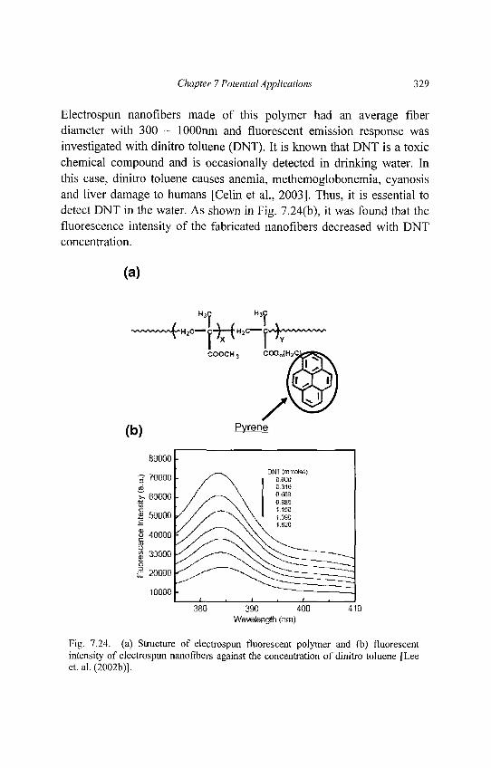
Chapter 7 Potential Applications 329
Electrospun nanofibers made of this polymer had an average fiberdiameter with 300 ~ lOOOnm and fluorescent emission response wasinvestigated with dinitro toluene (DNT). It is known that DNT is a toxicchemical compound and is occasionally detected in drinking water. Inthis case, dinitro toluene causes anemia, methemoglobonemia, cyanosisand liver damage to humans [Celin et al., 2003]. Thus, it is essential todetect DNT in the water. As shown in Fig. 7.24(b), it was found that thefluorescence intensity of the fabricated nanofibers decreased with DNTconcentration.
Fig. 7.24. (a) Structure of electrospun fluorescent polymer and (b) fluorescentintensity of electrospun nanofibers against the concentration of dinitro toluene [Leeet. al. (2002b)].
330 An Introduction to Electrospinning and Nanofibers
[Wang et. al. (2002b)] also adopted fluorescent monomer in theirsynthesized polymer, i.e., poly(acrylic acid)-poly(pyrene methanol)(PAA-PM). The electrospun nanofiber membranes of this polymer had100 ~ 400nm average fiber diameter and exhibited high fluorescentsensitivity with Hg2+, Fe3+ and DNT. Thus, optical sensors usingfluorescent polymer nanofibers could have potential.
Biosensors
Biosensors are the device which can detect or monitor the biologicalchange of human body. Bioengineering is one of the important researchfields in this century as the number of oldery people will dramaticallyincrease in the near future. Therapy with bioengineering technology ishigh requirement and this background brought biosensors to be a hottopic. [Wang et. al. (2004c)] considered to detect heme-containingrespiratory protein, so called cytochrome c. This protein is related to theconfirmation of myocardial infarction and detection of this protein isvery important to monitor the patient. Methyl viologen tethered to aligand that is sequestered by binding to a specific and biorelevant targetwas also discussed. For the monitoring cytochrome c and methylviologen, [Wang et. al. (2004c)] utilized electrospun cellulose acetate(CA) nanofibers coated by fluorescent layer, i.e., poly[2-(3-thienyl)ethanol butoxy carbonyl-methyl urethane] (H-PURET). The nanofiberspossessed 100 ~ 400nm average fiber diameter. It was found thatfluorescent intensity decreased with increasing concentration ofcytochrome c as well as methyl viologen. It was concluded that highfluorescent sensitivity was attributed to the high surface area to volumeration of the nanofibers and efficient interaction between the fluorescentpolymer and the analytes.
The group of [Sawicka et. al. (2005)] fabricated polyvinylpyrrolidone(PVP) nanofiber sensor incorporated with urease (urea decompositionenzyme) to detect urea, which can be used to check kidney and liverfunction problems. The behind mechanism of the nanofiber sensor is thefollowing chemical reaction which urea is converted to ammonia underthe existence of urease.
Chapter 7 Potential Applications 331
CO(NHi)2 + H2O • CO2 + 2NH3
Hence, it was expected that PVP nanofiber webs with urease highlyencourages the above chemical reaction. The electrospun PVP/ureasenanofibers exhibited 7 ~ lOOnm average fiber diameter and the sphericalaggregates of urease molecules with 10 ~ 800nm diameter were alsoobserved in the nanofiber network. It was found that the developednanofiber sensors reacted with low concentration of urea up to 0.5mM.Although complete reaction time was 20 minutes, the response of ureadetection was fast.
The Ramakrishna's group at National University of Singapore recentlydeveloped Nylon 6 nanofibers incorporated with gold particles asglucose sensors. Glucose detection is important for the patient whosuffers from diabetes. It is known that the glucose level increases in theblood if patient has serious condition of diabetes. Non-proper treatmentcauses necrosis of cells and blood vessels. [Lala et. al. (2005)] noticedthe glucose reaction under the enzyme of glucose oxidase (GOx) asfollows.
(GOx)C6H12O6 + O2 • C6H12O7 + H2O2(Glucose)
H2O2 • 2e- + 2H+ + O2
Here, hydrogen peroxide (H2O2) is further decomposed to oxygen andtwo protons and electrons. Thus, in order to measure the amount ofglucose, either change of oxygen concentration or H2O2 concentrationmay be considered. However due to the less sensitivity to monitor theoxygen and H2O2, [Lala et. al. (2005)] measured the output of thepotentiostat by the existence of gold particles on the nanofiber surface.
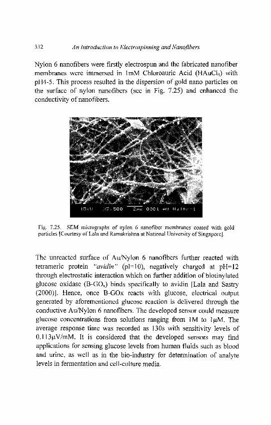
332 An Introduction to Electrospinning andNanofibers
Nylon 6 nanofibers were firstly electrospun and the fabricated nanofibermembranes were immersed in lmM Chloroauric Acid (HAuCl4) withpH4-5. This process resulted in the dispersion of gold nano particles onthe surface of nylon nanofibers (see in Fig. 7.25) and enhanced theconductivity of nanofibers.
Fig. 7.25. SEM micrographs of nylon 6 nanofiber membranes coated with goldparticles [Courtesy of Lala and Ramakrishna at National University of Singapore].
The unreacted surface of Au/Nylon 6 nanofibers further reacted withtetrameric protein "avidin" (pI=10), negatively charged at pH=12through electrostatic interaction which on further addition of biotinylatedglucose oxidase (B-GOX) binds specifically to avidin [Lala and Sastry(2000)]. Hence, once B-GOx reacts with glucose, electrical outputgenerated by aforementioned glucose reaction is delivered through theconductive Au/Nylon 6 nanofibers. The developed sensor could measureglucose concentrations from solutions ranging from 1M to luM. Theaverage response time was recorded as 130s with sensitivity levels of0.113uV/mM. It is considered that the developed sensors may findapplications for sensing glucose levels from human fluids such as bloodand urine, as well as in the bio-industry for determination of analytelevels in fermentation and cell-culture media.
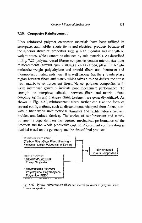
Chapter 7 Potential Applications 333
7.10. Composite Reinforcement
Fiber reinforced polymer composite materials have been utilized inaerospace, automobile, sports items and electrical products because ofthe superior structural properties such as high modulus and strength toweight ratios, which cannot be obtained by sole materials. As describedin Fig. 7.26, polymer-based fibrous composites contain micron-size fiberreinforcements (around 7um ~ 30um) such as carbon, glass, ultra-high-molecular-weight polyethylene and aramid fibers and thermoset andthermoplastic matrix polymers. It is well known that there is interphaseregion between fibers and matrix which takes a role to deliver the stressfrom matrix to reinforcement fibers. Hence, polymer composites withweak interphase generally indicate poor mechanical performance. Tostrength the interphase adhesion between fibers and matrix, silanecoupling agents and plasma-etching treatment are generally utilized. Asshown in Fig. 7.27, reinforcement fibers further can take the form ofseveral configurations, such as discontinuous chopped short fibers, non-woven fiber webs, unidirectional laminates and textile fabrics (woven,braided and knitted fabrics). The choice of reinforcement and matrixpolymer is dependent on the required mechanical performance of theproducts and the whole productive cost. Reinforcement configuration isdecided based on the geometry and the size of final products.
(Carbon Fiber, Glass Fiber, Ultra-High-Molecular-Weight Polyethylene, Kevlar)
^^, Polymer based I1 FjbrousCortiposites|
» Thermoset PolymersEpoxy, Vinylester — '
» Thermoplastic PolymersPolyethylene, Polypropylene,Polyamide, PEEK
Fig. 7.26. Typical reinforcement fibers and matrix polymers of polymer basedfibrous composites.
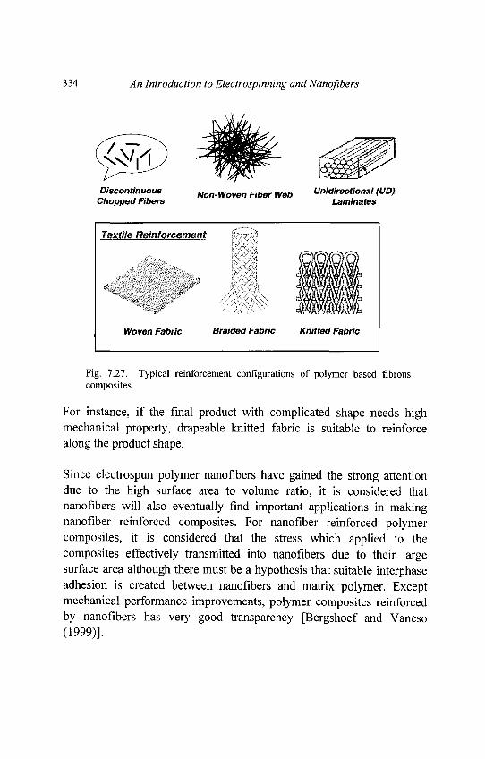
334 An Introduction to Electrospinning andNanoflbers
Fig. 7.27. Typical reinforcement configurations of polymer based fibrouscomposites.
For instance, if the final product with complicated shape needs highmechanical property, drapeable knitted fabric is suitable to reinforcealong the product shape.
Since electrospun polymer nanoflbers have gained the strong attentiondue to the high surface area to volume ratio, it is considered thatnanoflbers will also eventually find important applications in makingnanofiber reinforced composites. For nanofiber reinforced polymercomposites, it is considered that the stress which applied to thecomposites effectively transmitted into nanoflbers due to their largesurface area although there must be a hypothesis that suitable interphaseadhesion is created between nanoflbers and matrix polymer. Exceptmechanical performance improvements, polymer composites reinforcedby nanoflbers has very good transparency [Bergshoef and Vancso(1999)].
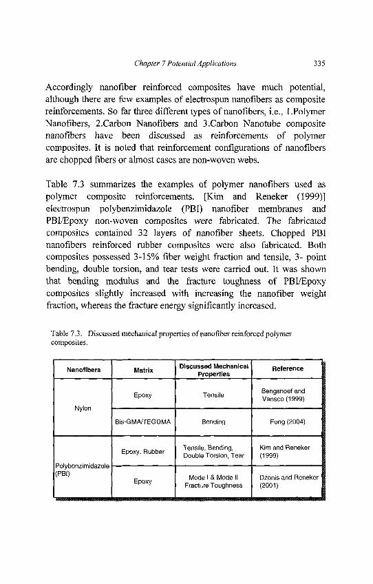
Chapter 7 Potential Applications 335
Accordingly nanofiber reinforced composites have much potential,although there are few examples of electrospun nanofibers as compositereinforcements. So far three different types of nanofibers, i.e., 1.PolymerNanofibers, 2.Carbon Nanofibers and 3.Carbon Nanotube compositenanofibers have been discussed as reinforcements of polymercomposites. It is noted that reinforcement configurations of nanofibersare chopped fibers or almost cases are non-woven webs.
Table 7.3 summarizes the examples of polymer nanofibers used aspolymer composite reinforcements. [Kim and Reneker (1999)]electrospun polybenzimidazole (PBI) nanofiber membranes andPBI/Epoxy non-woven composites were fabricated. The fabricatedcomposites contained 32 layers of nanofiber sheets. Chopped PBInanofibers reinforced rubber composites were also fabricated. Bothcomposites possessed 3-15% fiber weight fraction and tensile, 3- pointbending, double torsion, and tear tests were carried out. It was shownthat bending modulus and the fracture toughness of PBI/Epoxycomposites slightly increased with increasing the nanofiber weightfraction, whereas the fracture energy significantly increased.
Table 7.3. Discussed mechanical properties of nanofiber reinforced polymercomposites.
Nanofibers I M ^ I Discussed Mechanical I ReferenceProperties
_ T- i Benqshoef andEpoxy Tensi e ., 3 ,.,,•,,,„,p ' Vansco(1999)
Nylon
Bis-GM/VTEGDMA Bending Fong (2004)
n n ui. Tensile, Bending, Kim and Reneker
Epoxy, Rubber D o u b , e Torsion Tear (1999)
Polybenzimidazole
^P B I ) F Mode I & Mode II Dzenis and Reneker
p y Fracture Toughness (2001)
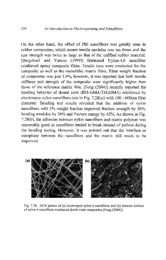
336 An Introduction to Electrospinning andNanojibers
On the other hand, the effect of PBI nanofibers was greatly seen inrubber composites, which means tensile modulus was ten times and thetear strength was twice as large as that of the unfilled rubber material.[Bergshoef and Vancso (1999)] fabricated Nylon-4,6 nanofiberreinforced epoxy composite films. Tensile tests were conducted for thecomposite as well as the monolithic matrix films. Fiber weight fractionof composites was just 3.9%, however, it was reported that both tensilestiffness and strength of the composite were significantly higher thanthose of the reference matrix film. [Fong (2004)] recently reported thebending behavior of dental resin (BIS-GMA/TEGDMA) reinforced byelectrospun nylon nanofibers (see in Fig. 7.28(a)) with 100 - 600nm fiberdiameter. Bending test results revealed that the addition of nylonnanofibers with 5% weight fraction improved fracture strength by 36%,bending modulus by 26% and fracture energy by 42%. As shown in Fig.7.28(b), the adhesion between nylon nanofibers and matrix polymer wasreasonably good as nanofibers tended to break instead of pullout duringthe bending testing. However, it was pointed out that the interface orinterphase between the nanofibers and the matrix still needs to beimproved.
Fig. 7.28. SEM photos of (a) electrospun nylon 6 nanofibers and (b) fracture surfaceof nylon 6 nanofibers reinforced dental resin composites [Fong (2004)].
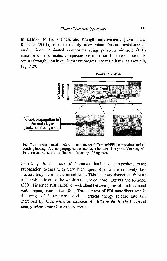
Chapter 7 Potential Applications 337
In addition to the stiffness and strength improvement, [Dzenis andReneker (2001)] tried to modify interlaminar fracture resistance ofunidirectional laminated composites using polybenzimidazole (PBI)nanofibers. In laminated composites, delamination fracture occasionallyoccurs through a main crack that propagates into resin layer, as shown inFig. 7.29.
Fig. 7.29. Delaminated fracture of unidirectional Carbon/PEEK composites underbending loading. A crack propagated the resin layer between fiber yarns [Courtesy ofFujihara and Ramakrishna, National University of Singapore].
Especially, in the case of thermoset laminated composites, crackpropagation occurs with very high speed due to the relatively lowfracture toughness of thermoset resin. This is a very dangerous fracturemode which leads to the whole structure collapse. [Dzenis and Reneker(2001)] inserted PBI nanofiber web sheet between plies of unidirectionalcarbon/epoxy composites [O2o]. The diameter of PBI nanofibers was inthe range of 300-500nm. Mode I critical energy release rate GIcincreased by 15%, while an increase of 130% in the Mode II criticalenergy release rate GIIc was observed.
338 An Introduction to Electrospinning and Nanofibers
Carbon nanofibers are also a good candidate for composite applicationsalthough they have been originally used in other applications as filters,high temperature catalysts, heat management materials in aircraft andsemiconductor device. Fabrication process of carbon nanofibers containselectrospinning of polyacrylonitrile (PAN) precursors, stabilization of as-spun PAN fibers at 270°C in the air and follows carbonization process ininert atmosphere at 600-1500°C [Dzenis and Wen (2002)]. AFM resultshowed that stiffness of carbon nanofibers is higher than that of as-spunPAN nanofibers. There is the curiosity about the mechanical property ofsingle carbon nanofiber as compared to conventional micron-size carbonfibers. Tensile strength and modulus of micron-size carbon fibers arearound 3000MPa and 230GPa. Since it is considered that micron-sizefibers possess structural defect, if fiber size is reduced to nano-size level,such structural defect may be reduced which leads to ultra excellentmechanical properties. Although there is limited information about themechanical performance of single carbon nanofiber, carbon nanofiberreinforced polymer composites have a large potential.
Another trial for composite reinforcements is carbon nanotube/polymercomposite nanofibers. The idea is that polymer nanofiber itself cannotachieve high mechanical performance and hence, carbon nano tube withexcellent stiffness and strength is combined with polymer nanofibers.[Ko et. al. (2003)] developed single wall carbon nanotubes(SWNT)/polyacrylonitrile (PAN) composite nanofiber yarns.Electrospun composite nanofibers possessed 50 ~ 200 run fiber diameterand weight fraction of nanotubes was 1 - 4 wt%. TEM results revealedthat nanotubes were dispersed in PAN nanofibers very well and wereparallel to the longitudinal direction of PAN fibers. As shown in AFMresult (see in Fig. 7.30), the indentation force of SWNT/PAN compositenanofibers was higher than neat PAN nanofibers. Accordingly,SWNT/PAN composite nanofibers can be expected as reinforcement inlinear, planer and 3D preforms (see in Fig. 7.27) for new generationpolymer composites.
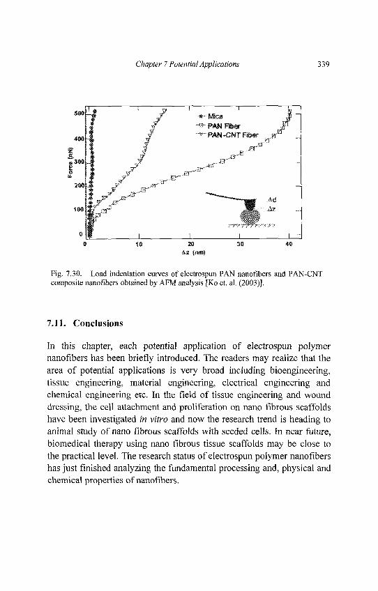
Chapter 7 Potential Applications 339
Fig. 7.30. Load indentation curves of electrospun PAN nanofibers and PAN-CNTcomposite nanofibers obtained by AFM analysis [Ko et. al. (2003)].
7.11. Conclusions
In this chapter, each potential application of electrospun polymernanofibers has been briefly introduced. The readers may realize that thearea of potential applications is very broad including bioengineering,tissue engineering, material engineering, electrical engineering andchemical engineering etc. In the field of tissue engineering and wounddressing, the cell attachment and proliferation on nano fibrous scaffoldshave been investigated in vitro and now the research trend is heading toanimal study of nano fibrous scaffolds with seeded cells. In near future,biomedical therapy using nano fibrous tissue scaffolds may be close tothe practical level. The research status of electrospun polymer nanofibershas just finished analyzing the fundamental processing and, physical andchemical properties of nanofibers.

340 An Introduction to Electrospinning andNanoflbers
In this respect, it can be said that the application researches of nanoflbershave just started. In other research fields, high research competition willbe estimated due to the surrounding world affairs of this century such asterrorism attacks and the rapid economical growth of undevelopedcountries. In order to encourage the application researches of electrospunnanoflbers, the cooperation of researchers from various scientific fields isimportant. The current authors look forward to seeing the bright future ofpeople's daily life by the novel application researches of nanofibers.
Appendix A
Glossary of Terms
Affinity membraneAffinity is a measure of the intrinsic binding strength of the ligandbinding reaction. Afinity is also known as the tendency of a molecule toassociate with another. The affinity of a drug is its ability to bind to itsbiological target (receptor, enzyme, transport system, etc.). Forpharmacological receptors it can be thought of as the frequency withwhich the drug, when brought into the proximity of a receptor bydiffusion, will reside at a position of minimum free energy within theforce field of that receptor. [IUPAC Medicinal Chemistry]. Henceaffinity membranes are chromatographic membranes with capturingagent molecules (affinity ligands) on the membrane surfaces. The affinityligands can specifically capture their corresponding target molecules(ligates) through specific interactions. Affinity membrane is differentfrom size-exclusion membranes like microfiltration, ultrafiltration,nanofiltration and reverse osmosis membrane that base their separationfunctions on size discrimination of the solute. Affinity membrane isdeveloped to permit the purification of molecules based onphysical/chemical properties or biological functions rather thanmolecular weight/size.
AmorphousLatin meaning without form. Non-crystalline structure
341
342 An Introduction to Electrospinning and Nanofibers
BiodegradableThe ability of a material to decompose under the action of biologicalagent such as bacteria, enzymes etc.
Chemical Vapor Deposition (CVD)A coating deposition process that is characterized by a chemical reactionproducing the desired film material as well as a waste stream. CVDprocesses frequently involve use of noxious and/or unstable materials. Inhard coating technology, CVD is an older process for the deposition ofTiN. It is generally only used for coating cemented carbide inserts,because of the extreme temperatures of the process. It's primaryadvantage is the ability to coat thick, tough layers for rough-cuttingapplications. Disadvantages include corner rounding, microcracking, andtemperature-induced problems.
CoalescenceAggregation of substances with affinity towards one another.
Conservation RelationsA group of relationships in engineering and physical sciences thatemphasizes the conservancy of some physical quantities, which are ofimportance in calculation of physical phenomena. A few examples aregiven as follows. Kirchhoff s Current Law states that the algebraic sumof the currents in all the branches which converge in a common electricalcircuit's node is equal to zero. Mass conservation states that the amountof mass in a closed-system (except nuclear reaction) remains constant.Momentum conservation states that the amount of momentum is asystem of colliding particles remains the same.
Contact angle(1) A contact angle is the angle between the solid surface (plate orvessel) and the liquid surface. (2) A means of quantifying the nonstickproperties of a coating by measuring the ability of a liquid to wet itssurface. (3) Also called the wetting angle.
Appendix A Glossary of Terms 343
CopolymersA polymer resulting from addition polymerization of two differentmonomers. The resulting copolymers have properties different fromeither of the homopolymers from the two monomers or the mechanicalmixture of the homopolymers.
CrystallinityThe presence of three-dimensional order on the level of atomicdimensions. In polymers, the range of order may be as small as about 2nm in one (or more) crystallographic direction(s) and is usually below 50nm in at least one direction. Polymer crystals frequently do not displaythe perfection that is usual for low-molecular mass substances. Polymercrystals that can be manipulated individually are often called polymersingle crystals. Pure and Appl. chem, 1989, 61, 769 IUPACMacromolecular Nomenclature.
Electric FieldA force field which defines what acceleration an electric charge placed atrest at any point in space will feel. Electric charges cause electric fieldsaround them, which then apply a force to any other electric charge placedin the field. The electric field E has both a magnitude and a direction ateach point in space, and the magnitude and direction of the resultingforce on a charge q at that point is given by F= qE. When you get a shockfrom a door handle after scuffing your feet on a carpet you feel the effectof an electric field accelerating electrons
Extracellular MatrixAnimal and human tissues are not made up solely of cells. A substantialpart of their volume is extracellular space, which is largely filled by anintricate network of macromolecules constituting the extracellular matrix(ECM) .The ECM is composed of a variety of proteins andpolysaccharides that are secreted locally and assembled into an organizedmeshwork in close association with the surface of the cell that producedthem.
344 An Introduction to Electrospinning and Nanofibers
ExtrusionThe act squeezing out a fluid through a die or confined region.
Glass Transition TemperatureIn polymer or glass chemistry, the temperature corresponding to theglass-to-liquid transition, below which the thermal expansion coefficientis low and nearly constant, and above which it is very high. Symbol: Tg.
HydrophobicCompounds that tend to repel water and does not dissolve or absorbwater.
Instability(1) The condition of a body if, when displaced from a state ofequilibrium, it continues, or tends to continue, to depart from the originalcondition. (2) The condition of a body or system which responds to aspecified disturbance by increasing the disturbance (perturbation) untilan irreversible change has taken place. Sometimes used in context tomean convective instability. (3)
Ligand/ligateIn chromatography, the word ligand is used to describe the capturingagents which is fixed on the membrane surface or in the column packingmaterials like agarose gel or silica gel particles. The target moleculeswhich is supposed to be captured by the membrane or column throughthe specific binding with the ligands are called ligate.
Maxwell FluidAn idealized behavior of fluid (but not solid) which acts in a viscoelasticmanner. Specifically, a Maxwell unit consists of a spring and a dashpot,representing an elastic solid and a viscous fluid respectively, in series sothat upon prescribed elongation of the Maxwell unit the elongated springcontracts back to its original length whilst energy is lost via the dashpot.This allows permanent deformation, as well as a flow-like behavior,which is characteristic of a fluid.
Appendix A Glossary of Terms 345
ModelingIn a loose sense, modeling simply refers to creating a simplifiedrepresentation of something else. A model can be a picture, a diagram ora mathematical formula. Modeling is an investigative technique whichuses a mathematical or physical representation of a system or theory totest for effects that changes in system components may have on theoverall functioning of the system. As an example, mathematicalmodeling using computers plays a major role in climate research, bysimulating how Earth's climate will respond to changes in atmosphericconcentrations of greenhouse gases. Hence modeling includes theoreticalcomputation of natural or industrial phenomenon using raw data andbasic properties.
Molecular WeightMolecular weight of the polymer is the sum of the molecular weight ofthe individual monomers
MorphologyThe study of form and structure of a substance without considering itsfunction.
Nanofiber MembraneA thin membrane that forms on the collecting plate during theelectrospinning process as a result of laying of solidified or semi-solidified jet on a two-dimensional surface. This membrane is also calleda nanofiber mesh or nanofiber web due to its network-like structure whenviewed from an electron microscope.
Nanofiber MeshSee nanofiber membrane
Nanofiber WebSee nanofiber membrane
346 An Introduction to Electrospinning and Nanofibers
Nanotechnology(1) The science of building devices at the molecular and atomic level.For example, a single data bit might be represented by only one atomsome time in the future. Beyond being used in computers andcommunications devices, nanotechnology could be used to build devices,change the properties of materials, and extensively in biotechnology. (2)Synonymous with molecular systems engineering. An interdisciplinaryfield where devices are constructed at the molecular scale and function atthis scale. This technology is expected to allow the construction of verycompact and high performance computing devices. (3) In recent generalusage, any technology related to features of nanometer scale: thin films,fine particles, chemical synthesis, advanced microlithography, and soforth. As introduced by the author, a technology based on the ability tobuild structures to complex, atomic specifications by means ofmechanosynthesis; this can be termed molecular nanotechnology.
NeckingA deformation phenomenon where there is a narrowing of a section of amaterial that is subjected to tensile stress.
NodeConceptualized beads. In this book, we refer to nodes as idealized pointmass that is equivalent to a segment of liquid jet.
PerturbationFunctionally incorporated noise to test the threshold and growth ofinstability.
Plasma TreatmentPlasma is a state of matter characterized by unbound negative electronsand positive ions which may conduct electrical current. It is known as thefourth state of matter, along with other states of matter: solids, liquidsand gases. Scientists believe that more than 99% of matter in theuniverse exists as plasma, including stars, lightning, and the AuroraBorealis. Hence plasma treatment is the use of ionized-gas forperforming materials treatment.
Appendix A Glossary of Terms 347
PorosityA condition of trapped pockets of air, gas, or vacuum within a solidmaterial, usually expressed as a percentage of the total nonsolid volumeto the total volume (solid plus nonsolid) of a unit quantity of material
Relative permittivityIndicates the ability of a material to store electrical energy when avoltage is applied to it. This may be considered a desirable property or anelectrical loss depending on the application.
Relaxation timeThe time constant of an exponential return of a system to equilibriumafter a disturbance
SpheruliteAn aggregate of ribbonlike polymer crystallites radiating from a commoncenter with amorphous region separating the crystallites.
SubstrateA surface on which an organism grows or is attached. An underlyinglayer; a substratum
Surface ModificationChanging the physical properties of a surface while retaining the physicalproperties of the bulk by attaching molecules or altering the molecules atthe surface such that these surface molecules can be made to function ina desired manner.
Surface tensionThe contracting force per unit length around the perimeter of a surface isusually referred to as surface tension if the surface separates gas fromliquid or solid phases, and interfacial tension if the surface separates twonongaseous phases. Surface tension can also be expressed in units ofenergy per unit surface area. For practical purposes surface tension isfrequently taken to reflect the change in surface free energy per unitincrease in surface area.
348 An Introduction to Electrospinning and Nanoflbers
SurfactantA molecule that lowers surface tension with a hydrophilic head thatsticks to water and a hydrophobic end that sticks to organic substance.
Tissue engineeringTissue engineering was defined by National Science Foundation (NSF)of USA in 1988 as follows "Tissue engineering is the application of theprinciples and methods of engineering and the life science toward thefundamental understanding of structure-function relationships in normaland pathological mammalian tissue and the development of biologicalsubstitutes to restore, maintain or improve functions." However, mostresearchers would think less formally of tissue engineering today as acombination of biology and engineering that aims to develop substitutetissue, to replace or otherwise restore function of damaged humantissues. Generally the tissue engineered implant will require a porous'scaffold' to direct the cells to grow in the correct physical form, and ofcourse, cells.
Tissue engineering scaffoldThe porous scaffold used to accommodate cells in tissue engineering.Tissue engineering scaffold should have properties like high porosity andinterconnectivity, proper strength and good bioactivity. If the tissueengineering scaffold is made from synthetic polymer, its surfaces usuallyneed to be modified to improve the cell adhesion. Most of the tissueengineering scaffolds are prepared using biodegradable materials.
TransconductanceThe creation of a current over two output points where a voltage isapplied to two input base points, as if the conductance is transferred fromone point to another.
Appendix A Glossary of Terms 349
ViscoelasticityThe dual nature of polymers, partly viscous fluid and partly elastic solid,is referred to as viscoelasticity. In flowing polymers viscoelasticity isresponsible for time-dependent properties, such as stress relaxation,normal stresses, very large elongational viscosities, and numerousunusual phenomena such as extrudate swell, entry flow vortices andsome flow instabilities.
ViscosityThe resistance to flow of a fluid (strictly speaking the resistance toshearing). It is defined as the ratio of shear stress (TangentialForce/Area) to shear rate (velocity/gap). The viscosity of a polymerdecreases as the shear rate increases. This property is referred to aspseudoplastic behavior or shear thinning. The viscosity of a polymer at(near) zero shear for a polymer like PE might be 5,000 to 10,000 Pa.swhile during flow in an extrusion channel it could be much lower (i.e.500 Pa.s or less). Melt flow index corresponds to just one point on aviscosity curve (actually inverse). High viscosity implies low melt indexand high molecular weight. Viscosity is measured in units of Pa.s orpoise. 1 Pa.s = 10 poise. The viscosity of water is 10-3 Pa.s (1 centipoise)and for a typical polymer melt at least one million times larger (i.e. over1000 Pa.s).
VolatilityThe capability of a liquid substance to be vaporized at room temperarureand pressure.
Appendix B
Useful Websites on Electrospinning andNanofibers
http://www.livescience.com/scienceoffiction/technovel_nanofiber_041124
.html
http://www.genomenewsnetwork.org/articles/06_03/nano.shtml
http://www.donaldson.com/en/filtermedia/support/datalibrary/003317.pdf
http://www.azonano.com/SearchResults.asp?MaterialKeyW ord=Nanofib
er
http://webpages.sdsmt.edU/~hfong/1.1 .html
http://academic.sun.ac.za/unesco/Conferences/Conference2003/ABSTR
ACTS/REN EKER. htm
http://www.eng.nus.edu.sg/EResnews/0302/sf/sf_3.html
http://fluid.ippt.gov.pl/sblonski/nanofibres.html
http://www.people.vcu.edu/~glbowlin/electrospinning.htm
http://tandecresearch.utk.edu/electroarticle.htm
http://www.tx. ncsu.edu/ci/nanosciences/articles_detail.cfm?article_headi
ng=Electrospinning
http://cuhwww.upr.clu.edu/~npinto/papers/1ncur2001.PDF
http://www.azonano.com/details.asp7ArticlelDM81
http://www.nanopolis.net/ES.php
http://web.mit.edu/rutledgegroup/projects/electrospinning.html
http://msewww.engin.umich.edu:81/people/milty/research/electrospinning
/
http://www.zyvex.com/nanotech/nano4/renekerAbstract.html
http://www.umassd.edu/engineering/textiles/research/electrospinning/we
bsite-electrospinning.html
350
Appendix B Useful Websites 351
http://ecsmeet.peerx-
press.org/ms_files/ecsmeet/2005/01/03/00022501/00/22501_0_art_file_
1_1104815851.pdf
http://www.nist.gov/sigmaxi/Posters04/stephens.html
http://www.che.vt.edu/Wilkes/electrospinning/electrspinning.html
http://www.explore-technology.eom/technology/E/Electrospinning.html
http://www.people.vcu.edu/~glbowlin/fibrinogen.htm
http://www.news.cornell.edU/Chronicle/03/9.11.03/electrospinning_fiber.h
tml
http://www.asc2004.com/Manuscripts/sessionM/MP-14.pdf
http://pubs.rsc.org/ej/JM/2005/b415094e.pdf
http://www.psicorp.com/casestudies/case_electrospin.shtml
http://www.ipme.ru/e-journals/RAMS/no_3503/kim1/kim1.pdf
http://www.nsti.Org/procs/Nanotech2004v3/9/T66.05
http://www.ntcresearch.org/current/year9/M98-D01.htm
http://www.jeccomposites.com/news/news_fiche.asp?id=904&
Bibliography
Aboulfaraj, M, Ulrich, B., Dahoun, A. and G'Sell, C. (1993). Spherulitic morphology ofisotactic polypropylene investigated by scanning electron microscopy. Polymer 34,23, pp. 4817-4825.
Acatay, K., Simsek, E., Akel, M., Menceloglu, Y.Z. (2003). Electrospirming of lowsurface energy quaternary ammonium salt containing polymers and theirantibacterial activity, Proceedings of the NATO Advanced Study Institute, Belek-Antalya, Turkey. Nato Science Series II, Mathematics, Physics and Chemistry 169,pp. 97-106.
Acatay, K., Simsek, E., Ow-Yang, C. and Menceloglu, Y.Z. (2004). Tunable,superhydrophobically.stable polymeric surfaces by electrospinning, Angew. Chem.Int. Ed. 43, pp. 5210-5213.
Adam, G. and Gibbs, J. H. (1965). On the Temperature Dependence of CooperativeRelaxation Properties in Glass-Forming Liquids. J Chem. Phys. 43, pp. 139-146.
Agency for Natural Resources and Energy, Japan. Energy in Japan2005?(http://www.enecho.meti.go.jp).
Alfrey, T. The Influence of Solvents Composition on the Specific Viscosities of PolymerSolutions. J. Coll. Sci. 2, 1, pp. 99-114.
Alfrey, T., Bartovics, A. and Mark, H. (1942). The Effect of Temperature and SolventType on the Intrinsic Viscosity of High Polymer Solutions. J. Am. Chem. Soc. 64,pp. 1557-1560.
Al-Najjar, M. M., Hamid, S. H. and Hamad, E. Z. (1996). The Glass TransitionTemperature of Nitrated Polystyrene/Poly(Acrylic Acid) Blends. Polym. Eng. Sci.36, pp. 2083-2087.
Angell, C. A. (1995). Formation of Glasses from Liquids and Biopolymers. Science.297, pp. 1924-1935.
Atala, A. and Lanza, R. P. (2002). Methods of Tissue Engineering. Academic Press USA.Ayutsede, J., Gandhi, M., Sukigara, S., Micklus, M., Chen, H. E. and Ko, F. (2005).
Regeneration of Bombyx mori silk by electrospinning. Part 3: characterization ofelectrospun nonwoven mat. Polymer 46, pp. 1625-1634.
352
Bibliography 353
Bamford, C.H., Al-Lamee, K.G., Pm-brick, M.D., Wear, T.J. (1992). Studies of a novelmembrane for affinity separations: I. Functionalisation and protein coupling, J.Chromatogr. A. 606, pp. 19-31.
Baumgarten, P. K. (1971). Electrostatic Spinning of Acrylic Microflbers. J. ColloidInterf. Sci. 36, pp. 75-79.
Benicewicz, B.C. and Hopper, P.K. (1991). Polymers for absorbable surgical sutures, J.Bioact. Compat. Polym. 6, pp. 64-94.
Bergshoef, M. M. and Vancso, G.J. (1999). Transparent Nanocomposites with UltrathinElectrospun Nylon-4,6 Fiber Reinforcement. Adv. Mater. 11, pp. 1362-1365.
Berkland, C, Pack, D. W. and Kim, K. (2004). Controlling surface nano-structure usingflow-limited field-injection electrostatic spraying (FFESS) of poly(D,L-lactide-co-glycolide). Biomaterials. 25, pp. 5649-5658.
Bhattarai, N., Cha, D.I., Bhattarai, S.R., KM, M.S. and Kim, H.Y. (2003). Biodegradableelectrospun mat: novel block copolymer of poly (p-dioxanone-co-L-lactide)-block-poly(ethylene glycol), J. Polym. Sci. Pt. B-Polym. Phys. 41, pp. 1955-1964.
Bhattarai, S.R., Bhattarai, N., Yi, H.K., Hwang, P.H., Cha, D.I. and Kim, H.Y. (2004).Novel biodegradable electrospun membrane: scaffold for tissue engineering,Biomaterials. 25, pp. 2595-2602.
Bigg, D. M. (1979). Mechanical and conductive properties of metal fibre-filled polymercomposites, Composites. 10, pp. 95-100.
Bini, T.B., Gao, S.J., Tan, T.C., Wang, S., Lim, A., Hai, L.B. and Ramakrishna, S.(2004). Electrospun poly(L-lactide-co-glycolide) biodegradable polymer nanofibretubes for peripheral nerve regeneration, Nanotechnology. 15, pp. 1459-1464.
Boeden, H.F., Pommerening, K., Becker, M., Rupprich, C, Holtzhauer, M. (1991). Beadcellulose derivatives as supports for immobilization and chromatographicpurification of proteins, J. Chromatogr. A. 552, pp.389-414.
Bognitzki, M., Czado, W., Frese, T., Schaper, A., Hellwig, M., Steinhart, M., Greiner, A.and Wendorff, J. H. (2001). Nanostructured Fibers via Electrospinning. Adv.Mater. 13, pp. 70-72.
Bognitzki, M., Hou, H., Ishaque, M., Frese, T., Hellwig, M., Schwarte, C, Schaper, A.,Wendorff, J.H. and Greiner, A. (2000). Polymer, metal, and hybrid nano- andmesotubes by coating degradable polymer template fibers (TUFT Process). AdvMater, 12, 9, pp. 637-640.
Boland, E. D., Wnek, G. E., Simpson, D. G., Palowski, K. J. and Bowlin, G. L. (2001).Tailoring tissue engineering scaffolds using electrostatic processing techniques: Astudy of poly(glycolic acid) electrospinning. J. Macromol. Sci. Pur Appl. Chem.A38, 12, pp. 1231-1243.
Boland, E. D, Coleman, B. D, Barnes, C. P, Simpson, D. G, Wnek, G. E and Bowlin, G.L. (2005). Electrospinning polydioxanone for biomedical applications. Acta.Biomater. l,pp. 115-123.
Bornat, A. (1987). Production of electrostatically spun products, US Patent No.4,689,186.
354 An Introduction to Electrospinning andNanofibers
Bowlin, G.L., (2003) Electrospinning used to create small blood vessels.http://www.futurepundit.com.
Brown, I.G. (1993). Metal-ion implantation for large-scale surface modification, J. Vac.Sci. Technol. A. 11, pp. 1480-1485.
Brunauer, S., Emmett, P. and Teller, E. (1938). Adsorption of gases in multimolecularlayers, J. Amer. Chem. Soc. 60, pp. 309-319.
Buchko, C. J, Chen, L. C, Shen, Y. and Martin, D. C. (1999). Processing andmicrostructural characterization of porous biocompatible protein polymer thinfilms. Polyme.r 40, pp. 7397-7407.
Buer, A., Ugbolue, S.C. and Warner, S.B. (2001). Electrospinning and properties of somenanofibers, Tex. Res. J. 71, 4, pp. 323-328.
Bunge, R.P. and Bunge, M.B. (1983). Interrelationship between Schwann cell functionand extracellular matrix production, Trends Neurosci. 6, pp. 499-505.
Bureau, E., Cabot, C, Marais, S. and Saiter, J. M. (2005). Study of the a-relaxation ofPVC, EVA and 50/50 EVA70/PVC blend. Eur. Polym. J. 41, pp. 1152-1158.
Callister, W. D. (1997). Materials Science and Engineering An Introduction. John Wiley& Sons.
Cambell, D. and Pethrick, R.A., White, J.R. (2000a). Chapter 10: Scanning electronmicroscopy, Polymer Characterization, Physical techniques, Second Edition, pp.293-325, Stanley Thornes (Publishers) Ltd.
Cambell, D. and Pethrick, R.A., White, J.R. (2000b). Chapter 8: X-ray diffraction,Polymer Characterization, Physical techniques, Second Edition, pp. 194-236,Stanley Thornes (Publishers) Ltd.
Cambell, D. and Pethrick, R.A., White, J.R. (2000c). Chapter 5: Vibrationalspectroscopy: infra-red and raman spectroscopy, Polymer Characterization,Physical techniques, Second Edition, pp. 67-107, Stanley Thornes (Publishers) Ltd.
Campo, F. F. D., Paneque, A. , Ramirez, J. M. and Losada, M. (1963). Thermaltransitions in collagen. Biochim. Biophys. Acta. 66, pp. 448-452.
Caplan, A.I. (1991). Mesenchymal stem cells, J. Orthopaed. Res. 9, pp. 641-650.Carbonetto, S. (1984). The extracellular matrix of the nervous system. Trends Neurosci.
7, pp. 382-387.Caruso R.A., Schattka J.H. and Greiner A. (2001). Titanium dioxide tubes from sol-gel
coating of electrospun polymer fibers. Advanced Materials, 13, 20, pp. 1577-1579.Casper, C.L., Stephens, J.S., Tassi, N.G., Chase, D.B. and Rabolt, J.F. (2004).
Controlling surface morphology of electrospun polystyrene fibers: Effect ofhumidity and molecular weight in the electrospinning process, Macromolecules.37, pp. 573-578.
Celin, S.M., Pandit, M., Kapoor, J.C. and Sharma, R.K. (2003). Studies on photo-degradation of 2,4-dinitro toluene in aqueous phase, Chemosphere. 53, pp. 63-69.
Chan, CM., Ko, T.M., Hiraoka, H. (1996). Polymer surface modification by plasmas andphotons, Surf. Sci. Rep. 24, pp.3-54
Bibliography 355
Chen, K. B., Lee, K. C, Ueng, T. H. and Mou, K. J. (2002). Electrical and impactproperties of the hybrid knitted inlaid fabric reinforced polypropylene composites.Compos. Part A-Appl S. 33, pp. 1219-1226.
Chen, Z., Foster, M.D., Zho,u W., Fong, H., Reneker, D.H., Resendes, R. and Manners, I.(2001). Structure of poly(ferrocenyldimethylsilane) in electrospun nanofibers.Macromol., 34(18), pp. 6156-6158.
Cheng, C.L., Wan, C.C., Wang, Y.Y. and Wu, M.S. (2005). Thermal shutdown behaviorof PVdF-HFP based polymer electrolytes comprising heat sensitive cross-linkableoligomers, J. Power Sources (in press).
Chipara, M., Hui, D., Notingher, V., Chipara, M. D., Lau, K. T., Sankar, J. andPanaitescu, D. (2003). On polyethylene-polyaniline composites, Compos Part B-Eng34, pp. 637-645.
Choi, S.S., Lee, S.G., Im, S.S., Kim, S.H. and Joo, Y.L. (2003a). Silica nanofibers fromelectrospinning/sol-gel process. J. Mater. Sci. Lett., 22(12), pp. 891-893.
Choi, S.W., Jo, S.M., Lee, W.S., Kim, Y.R. (2003b). An electron poly(vinylidenefluoride) nanofibrous membrane and its battery applications, Adv. Mater. 15, 23,pp. 2027-2032.
Choi, J.S., Lee, S.W., Jeong, L., Bae, S.H., Min, B.C., Youk, J.H. and Park, W.H.(2004a). Effect of organosoluble salts on the nanofibrous structure of electrospunpoly(3-hydroxybutyrate-co-3-hydroxyvalerate). International Journal of BiologicalMacromolecules, 34, 4, pp. 249-256.
Choi, S. S., Lee, Y. S., Joo, C. W., Lee, S. G., Park, J. K. and Han, K. S. (2004b).Electrospun PVDF nanofiber web as polymer electrolyte or separator. ElectrochimActa 50, pp. 338-342.
Choi, S. S., Lee, S. G., Joo, C. W., Im, S. S. and Kim, S. H. (2004c). Formation ofinterfiber bonding in electrospun poly(etherimide) nanofiber web. J. Mater. Sci. 39,pp. 1511-1513.
Choi, S.S., Chu, B., Lee, S.G., Lee, S.W., Im, S.S., Kim, S.H. and Park, J.K. (2004d).Titanium-doped silica fibers prepared by electrospinning and sol-gel process. J.Sol-Gel Sci. Technol., 30(3), pp. 215-221.
Choi, S.W., Kim, J.R, Jo, S.M., Lee, W.S. and Kim, B.C. (2004e). Electrospun PVdF-based fibrous polymer electrolytes for lithium ion polymer batteries, Electrochim.Acta. 50, 1, pp. 69-75.
Christanti, Y. and Walker, L. M. (2001). Surface tension driven jet break up of strain-hardening polymer solutions. J. Non-Newton. Fluid. 100, pp. 9-26.
Christie, S., Scorsone, E., Persaud, K, Kvasnik, F. (2003). Remote detection of gaseousammonia using the near infrared transmission properties of polyaniline, SensorActuat B-Chem. 90, pp. 163-9.
Chu, B., Hsiao, B. S. and Fang, D. (2004) Apparatus and methods for electrospinningpolymeric fibers and membranes. US Patent 6713011 B2.
Chu, P.K., Chen, J.Y., Wang, L.P., Huang, N. (2002). Plasma-surface modification ofbiomaterials, Mater. Sci. Eng. R-Rep. 36, pp.143-206.
356 An Introduction to Electrospinning and Nanofibers
Chua, K.N., Lim, W.S., Zhang, P., Lu, H., Wen, J., Ramakrishna, S., Leong, K.W., Mao,H.Q. (2005). Stable immobilization of rat hepatocyte spheroids on galactosylatednanofiber scaffold, Biomaterials 26, 2537.
Chun, Y. S., Lee, H. S. and Kim, W. N. (1996). Thermal Properties and Morphology ofBlends of Poly(ether imide) and Polycarbonate. Polym. Eng. Sci. 36, pp. 2694-2972.
Chung, H.Y. (2004). Polymer, polymer microfiber, polymer nanofiber and applicationsincluding filter structures, US patent 6,743,273.
Chung, T.W., Liu, T.W., Wang, D.Z. and Wang, S.S. (2003). Enhancement of the growthof human endothelial cells by surface roughness at nanometer scale, Biomaterials.24, pp. 4655-4661.
Clark, A.L. (1938). The Critical State of Pure Fluids. Chem Rev. 23, pp. 1-15.Clough, R.L., Gillen, K.T., Dole, M. (1991). Chapter 3 In: Irradiation effects on
polymers, ed by Clegg, D.W., Collyer, A.A., Elsevier applied science, New York.Coombes, A.G.A., Verderio, E., Shaw, B. and Downes, D. (2002). Biocomposites ofnon-
crosslinked natural and synthetic polymers, Biomaterials. 23, pp. 2113-2118.Corradini, E., Mattoso, L. H. C, Guedes, C. G. F. and Rosa, D. S. (2004). Mechanical,
thermal and morphological properties of poly(e-caprolactone)/zein blends. Polym.Advan. Technol. 15, pp. 340-345.
Daane, J. H. and Barker, R. E. Jr. (1964). Multiple glass transitions in cellulose 2.5acetate. J. Polym. Sci. Pol. Lett. 2, pp. 343-347.
Dai, H., Gong, J., Kim, H. and Lee, D. (2002). A novel method for preparing ultra-finealumina-borate oxide fibres via an electrospinning technique. Nanotechnology. 13,pp. 674-677.
Dai, N.T., Williams, M.R., Khammo, N., Adams, E.F. and Coombes, A.G.A. (2004).Composite cell support membranes based on collagen and polycaprolactone fortissue engineering of skin, Biomaterials. 25, pp. 4263-4271.
Dalton, P. D., Klee, D. and Moller, M. (2005). Electrospinning with dual collectionrings. Polym. Commun. 46, 611-614.
Davis, S. A., Burkett, S. L., Mendelson, N. H. and Mann, S. (1997). Bacterial templatingof ordered macrostructures in silica and silica-surfactant mesophases. Nature. 385,pp. 420-423.
de Moel, K, van Ekenstein, G.O.R.A., Nijland, H., Polushkin, E., ten Brinke, G., MakiOntto, R. and Ikkala, O. (2001). Polymeric nanofibers prepared from self organizedsupramolecules. Chem. Mater., 13(12), pp. 4580-4583.
Deam, J. R. and Maddox, R. N. (1970). Interfacial Tension in Hydrocarbon Systems. J.Chem. Eng. Data. 15, pp. 216-222.
Deitzel, J. M., Kleinmeyer, J. D., Hirvonen, J. K. and Tan, N. C. B. (2001a). Controlleddeposition of electrospun poly(ethylene oxide) fibers. Polymer. 42, pp. 8163-8170.
Deitzel, J. M., Kleinmeyer, J., Harris, D. and Tan, N. C. B. (2001b). The effect ofprocessing variables on the morphology of electrospun nanofibers and textiles.Polymer. 42, pp. 261-272.
Bibliography 357
Deitzel, J.M., Kosik, W., McKnight, S.H., Tan, N.C.B., DeSimone, J.M. and Crette, S.
(2002). Electrospinning of polymer nanofibers with specific surface chemistry,
Polymer. 43, pp. 1025-1029.
Demir, M. M., Yilgor, I., Yilgor, E. and Erman, B. (2002). Electrospinning of
polyurethane fibers. Polymer. 43, pp. 3303-3309.
Demir, M.M., Gulgun, M.A., Menceloglu, Y.Z., Erman, B., Abramchuk, S.S., Makhaeva,
E.E., Khokhlov, A.R., Matveeva, V.G. and Sulman, M.G. (2004). Palladium
nanoparticles by electrospinning from poly(acrylonitrile-co-acrylic acid)-PdC12
solutions. Relations between preparation conditions, particle size, and catalytic
activity, Macromolecules. 37, pp. 1787-1792.
Dersch, R., Liu, T., Schaper, A.K., Greiner, A. and Wendorff, J.H. (2003). Electrospun
nanofibers: Internal structure and intrinsic orientation, J. Polym. Sci. Pt. B-Polym.
Phys. 41, pp. 545-553.
Desai, S.M., Singh, R.P. (2004). Surface modification of polyethylene: long-term
properties ofpolyolefins, Adv. Polym. Sci. 169, pp.231-293.
Dharmaraj, N., Park, H.C., Kim, C.K., Kim, H.Y. and Lee, D.R. (2004a). Nickel titanate
nanofibers by electrospinning. Materials Chemistry and Physics, 87, pp. 5-9.
Dharmaraj, N., Park, H.C., Lee, B.M., Viswanathamurthi, P., Kim, H.Y. and Lee, D.R.
(2004b). Preparation and morphology of magnesium titanate nanoflbres via
electrospinning. Inorganic Chem Commu, 7, pp. 431-433.
Ding, B., Kim, H.Y., Lee, S.C., Shao, C.L., Lee, D.R., Park, S.J., Kwag, G.B. and Choi,
K.J. (2002). Preparation and characterization of a nanoscale poly(vinyl alcohol)
fiber aggregate produced by an electrospinning method, J. Polym. Sci. Pt. B-
Polym. Phys. 40, pp. 1261-1268.
Ding B., Kim H., Kim C , Khil M. and Park S. (2003). Morphology and crystalline phase
study of electrospun TiO2-SiO2 nanofibres. Nanotechnology, 14, pp. 532-537.
Ding, B., Kim, J., Miyazaki, Y. and Shiratori, S. (2004a). Electrospun nanofibrous
membranes coated quartz crystal microbalance as gas sensor for NH3 detection.
Sensor Actuat B-Chem. 101, pp. 373-380.
Ding, B., Yamazaki, M. and Shiratori, S. (2004b). Electrospun fibrous polyacrylic acid
membrane-based gas sensors, Sensor Actuat B-Chem. 106, pp. 477-483.
Ding, B., Kimura, E., Sato, T., Fujita, S. and Shiratori, S. (2004c). Fabrication of blend
biodegradable nanofibrous nonwoven mats via multi-jet electrospinning. Polymer.
45, pp. 1895-1902.
Dong, H., Bell, T. (1999). State-of-the-art overview: ion beam surface modification of
polymers towards improving tribological properties, Surf. Coat. Technol. I l l , 1,
pp. 29-40
Dresselhaus, M. S. (1998). New tricks with nanotubes. Nature. 391, pp. 19-20.
Drew, C , Liu, X., Ziegler, D., Wang, X., Bruno, F.F., Whitten, J., Samuelson, L.A.,
Kumar, J. (2003). Metal Oxide-Coated Polymer Nanofibers, Nano Lett. 3, pp. 143.
358 An Introduction to Electrospinning and Nanoflbers
Dror, Y., Salalha, W., Khalfin, R. L., Cohen, Y., Yarin, A. L. and Zussman, E. (2003).Carbon Nanotubes Embedded in Oriented Polymer Nanoflbers by Electrospinning.Langmuir. 19, pp. 7012-7020.
Duan, B., Dong, C. H., Yuan, X.Y. and Yao, K. D. (2004). Electrospinning of chitosansolutions in acetic acid with polyethylene oxide). J. Biomat. Sci.-Polym. E. 15, pp.797-811.
Dzenis, Y.A., Reneker, D.H. (2001). Delamination resistant composites prepared bysmall diameter fiber reinforcement at ply interfaces, US Patent No. 6,265,333Bl.Dzenis, Y.A. and Wen, Y.K. (2002). Continuous carbon nanoflbers fornanofiber composites, Mat Res Soc Symp Proc. 702, pp. U5.4.1-U5.4.6.
Elbert, D.L., Hubbell, J.A. (1996). Surface treatment of polymers for biocompatibility,Annu. Rev. Mater. Sci., 26, pp.365.
Elias, K.E., Price, R.L. and Webster, T.J. (2002). Enhanced functions of osteoblasts onnanometer diameter carbon nanoflbers, Biomaterials. 23, pp. 3279-3287.
Ellison, C. J. and Torkelson, J. M. (2003). The distribution of glass-transitiontemperatures in nanoscopically confined glass formers. Nat. Mater. 2, pp. 695-700.
Emig, D., Klimmek, A., Raabe, E. (2002). Dust filter bag containing nano non-woventissue. US Patent 6,395,046Bl.
Emmenegger, C. H., Mauron, P. H., Sudan, P., Wenger, P., Hermann, V., Gallay, R. andZuttel, A. (2003). Investigation of electrochemical double-layer (ECDL) capacitorselectrodes based on carbon nanotubes and activated carbon materials. J. PowerSources. 124, pp. 321-329.
Farag, M. M. (1989). Selection of Materials and Manufacturing Processes forEngineering Design, Prentice Hall, New York.
Feng, J.J. (2002). The stretching of an electrified non-Newtonian jet: A model forelectrospinning. Phys. Fluids, 14(11), pp. 3912-3926.
Feng, J.J. (2003). Stretching of a straight electrically charged viscoelastic jet. J. Non-Newtonian Fluid. Mech., 116(1), pp. 55-70.
Feng, L., Li, S.H., Li, H i , Zhai, J., Song, Y.L., Jiang, L. and Zhu, D.B. (2002). Superhydrophobic surface of aligned polyacrylonitrile nanoflbers. Angew. Chem. Int.Ed., 41(7), pp. 1221-1223.
Fennessey, S.F. and Farris, R.J. (2004). Fabrication of aligned and molecularly orientedelectrospun polyacrylonitrile nanofibers and the mechanical behavior of theirtwisted yarns, Polymer, 45, pp. 4217-4225.
Ferguson, J. and Zemblowski, Z. (1991). Applied Fluid Rheology. Elsevier SciencePublishers Ltd, Great Britain.
Fertala, A., Han, W. B. and Ko, F. K. (2001) Mapping critical sites in collagen II forrational design of gene-engineered proteins for cell-supporting materials, J.Biomed. Mater. Res. 57, pp. 48-58.
Fong, H. (2004). Electrospun nylon 6 nanofiebr reinforced BIS-GMA/TEGDMA dentalrestorative composite resins, Polymer. 45, pp. 2427-2432.
Bibliography 359
Fong, H. and Reneker, D.H. (1999). Elastomeric nanofibers of styrene-butadiene-styrenetriblock copolymer, J. Polym. Sci. Pt. B-Polym. Phys. 37, pp. 3488-3493.
Fong, H., Chun, I., Reneker, D. H. (1999). Beaded nanofibers formed duringelectrospinning. Polymer. 40, pp. 4585-4592.
Fong, H., Liu, W.D., Wang, C.S. and Vaia, R.A. (2002). Generation of electrospun fibersof nylon 6 and nylon 6-montmorillonite nanocomposite, Polymer. 43, pp. 775-780.
Formhals A. (1934). Process and apparatus for preparing artificial threads. US Patent.1,975,504.
Fraga, A. N. and Williams, R. J. J. (1985). Thermal Properties of gelatin films. Polymer.26, pp. 113-118.
Freed, L.E. and Vunjak-Novakovic, G. (1995). Tissue engineering of cartilage.Biomedical Engineering. Hartford, CRC Press, pp. 1788-806.
Fujihara, K., Kotaki, M. and Ramakrishna, S. (2005). Guided bone regenerationmembrane made of Polycaprolactone / calcium carbonate composite nano fibers,Biomaterials, 29, 16, pp. 4139-4147.
Gao, Y., Xiu, Y. Y., Pan, Z. Q., Wang, D. N., Hu, C. P. and Ying, S. K. (1994). Effect ofAromatic Diamine Extenders on the Morphology and Property of RIMPolyurethane-Urea. J. Appl. Polym. Sci. 53, l,pp. 23-29.
Gershon, B., Marom, G. and Cohn, D. (1990). New arterial prostheses by filamentwinding, Clinical Materials. 5, pp. 13-27.
Ghiggino, P.K. (1989). Chapter 3 in: The effects of radiation on high-technologypolymers, ed by Reichmanis, E., O'Donnell, J.H., American Chemical Society,Washington.
Gibson, H.S. and Gibson, P. (2002). Use of Electrospun Nanofibers for aerosol filtrationin Textile Structures. U.S. Army Soldier Systems Center, AMSSB-RSS-MS(N)Natick, Massachusetts, 01760-5020.
Gibson, P., Schreuder-Gibson, H. and Pentheny, C. (1998). Electrospinning technology:direct application of tailorable ultrathin membranes, J. Coated Fabric. 28, pp. 63-72.
Gibson, P.W., Schreuder-Gibson, H.L. and Riven, D. (1999). Electrospun fiber mats:transport properties, AIChE J. 45, 1, pp. 190-195.
Godovsky, Y. K. and Slonimsky, G. L. (1974). Kinetics of Polymer Crystallization fromthe Melt (Calorimetric Approach). J. Polym. Sci. 12, pp. 1053-1080.
Gong, J., Shao, C.L., Yang, G.C., Pan, Y. and Qu, L.Y. (2003). Preparation of ultra-finefiber mats contained H4SiW12O40. Inorganic Chem Commu, 6, pp. 916-918
Gordon G. A. (1971). Glass Transition in Nylons. J. Polym. Sci. 9, pp. 1693-1702.Gouma, P.I. (2003). Nanostructured polymorphic oxides for advanced chemosensors,
Rev. Adv. Mater. Sci. 5, pp.147-154.Grace, J.M., Gerenser, L.J. (2003). Plasma treatment of polymers, J. Dispersion Sci.
Technol. 24, 3-4, pp. 305-341.
360 An Introduction to Electrospinning and Nanoflbers
Grad, S., Kupcsik, L., Gogolewski, S. and Alini, M. (2003). The use of biodegradablepolyurethane scaffolds for cartilage tissue engineering: potential and limitations,Biomaterials. 24, pp. 5163-5171.
Grafe, T.H. and Graham, K.M. (2003). Nanofiber webs from electrospinning.Nonwovens in Filtration - Fifth International Conference, pp. 1 -5.
Graham, K., Gibson, H.S., Gogins, M. (2003). Incorporation of Electrospun Nanoflbersinto Functional Structures, Presented at INTC 2003, September 15-18, Baltimore,MD.
Graham, K., Gogins, M. and Schreuder-Gibson, H. (2004). Incorporation of electrospunnanofibers into functional structures, hit. Nonwovens J. Summer, pp. 21-27.
Grande, D.A., Halberstadt, C, Schwartz, R. and Manji, R. (1997). Evaluation of matrixscaffolds for tissue engineering of articular cartilage grafts, J. Biomed. Mater. Res.34, pp. 211-220.
Gregg, S.J. and Sing, K.W.S. (1982). Adsorption, Surface Area and Po:osity, AcademicPress, London.
Griffith, L. G. (2000). Polymeric Biomaterials, Acta Mater. 48, pp. 263-277.Griffiths, C. H., Okumura, K. and VanLaeken, A. (1977). Influence of Chemical
Modification (Bromination) on Structure and Charge Transport in PolyfN-Vinylcarbazole). J. Polym. Sci.Pol. Phys.15, pp. 1627-1639.
Groiztsch, D. and Fahrbach, E. (1986). Microporous multilayer nonwoven material formedical applications, US Patent 4,618,524.
Guan, H., Shao, C, Chen, B., Gong, J. and Yang, X. (2003a). A novel method for makingCuO superfine fibres via an electrospinning technique. Inorganic Chem Commu, 6,11, pp. 1409-1411.
Guan, H., Shao, C, Wen, S., Chen, B., Gong, J. and Yang, X. (2003b). A novel methodfor preparing Co3O4 nanofibers by using electrospun PVA/cobalt acetatecomposite fibers as precursor. Mater Chem Phy, 82, 3, pp. 1002-1006.
Guan, H., Shao, C, Liu, Y, Yu, N. and Yang, X. (2004). Fabrication of NiCo2O4nanofibers by electrospinning. Solid State Commu, 131 pp. 107-109.
Gupta, P. and Wilkes, G. L. (2003). Some investigations on the fiber formation byutilizing a side-by-side bicomponent electrospinning approach. Polymer, 44, pp.6353-6359.
Hajra, M.G., Mehta, K. and Chase, G.G. (2003). Effects of humidity, temperature, andnanofibers on drop coalescence in glass fiber media, Sep. Purif. Technol. 30, 1, pp.79-98.
Harris, J. (1977). Rheology and non-Newtonian flow. Longman, New York.Hartgerink, J.D., Beniash, E. and Stupp, S.I. (2001). Self-assembly and mineralization of
peptide-amphiphile nanofibers. Science, 294(5547), pp. 1684-1688.Hashmi, S.A., Kumar, A. and Tripathi, S.K. (2005). Investigations on electrochemical
supercapacitors using polypyrrole redox electrodes and PMMA based gelelectrolytes, Euro. Polym J. (in press).
Bibliography 361
Hattori, T. and Wakitani, S. (2002). Articular Cartilage regeneration, Clin Calcium. 12, 2,pp. 217-221.
He, W., Ma, Z.W., Yong, T., Teo, W.E. and Ramakrishna, S. (2005a). Fabrication ofcollagen-coated biodegradable copolymer nanofiber and their potential forendothelial cell growth, Biomaterials (submitted).
He, W., Yong, T., Teo, W.E., Ma, Z.W., Ramakrishna, S. (2005b). Fabrication andendothelialization of collagen-blended biodegradable polymer nanofiber: potentialvascular grafts for the blood vessel tissue engineering. Tissue Eng. Accepted.
Hildebrand, J. H. and Robert, L. S. (1950). The solubility of Nonelectrolytes, 3rd edition,Reinhold, New York.
Hirai, J. and Matsuda, T. (1996). Venous reconstruction using hybrid vascular tissuecomposed of vascular cells and collagen: tissue regeneration process, CellTransplant. 5, pp. 93-105.
Hirai, J., Kanda, K., Oka, T. and Matsuda, T. (1994). Highly oriented, tubular hybridvascular tissue for a low pressure circulatory system, ASAIO J, 40, pp. M383-M388.
Hoerstrup, S.P., Kadner, A., Breymann, C, Maurus, C.F., Guenter, C.I. and Sodian, R.(2002). Living, autologous pulmonary artery conduits tissue engineered fromhuman umbilical cord cells. Ann. Thorac. Surg. 74, pp. 46-52.
Hoerstrup, S.P., Zund, G., Sodian, R., Schnell, A.M., Grunenfelder, J. and Turina, M.I.(2001). Tissue engineering of small caliber vascular grafts, Eur. J. Cardiothorac.Surg. 20, pp. 164-169.
Hohman, M.M., Shin, M., Rutledge, G. and Brenner, M.P. (2001a) Electrospinning andelectrically forced jets. I. Stability theory. Phys. Fluids, 13(8), pp. 2201-2220.
Hohman, M.M., Shin, M., Rutledge, G. and Brenner, M.P. (2001b) Electrospinning andelectrically forced jets. H. Applications. Phys. Fluids, 13(8); 2221-2236.
Holland, S., Tighe, BJ. and Gould, P.L. (1986). Polymers for biodegradable medicaldevices. I. The potential of polyesters as controlled macromolecular releasesystems, J. Control. Release, 4, pp. 155-180.
Hong, K.H., Oh, K.W. and Kang, T.J. (2005). Preparation of conducting nylon-6electrospun fiber webs by the in situ polymerization of polyaniline, J. Appl. Poly.Sci. 96, pp. 983-991.
Hou, H. and Reneker, D. H. (2004). Carbon Nanotubes on Carbon Nanofibers: A NovelStructure Based on Electrospun Polymer Nanofibers. Adv Mater. 16, pp. 69-73.
Hou, H.Q., Jun, Z., Reuning, A., Schaper, A., Wendorff, J.H. and Greiner, A. (2002).Poly(p-xylene) nanotubes by coating and removal of ultrathin polymer templatefibers. Macromolecules, 35, pp. 2429-2431.
Hsu, C. M. and Shivakumar, S. (2004). N,N-Dimethylformamide Additions to theSolution for the Electrospinning of Poly(e-caprolactone) Nanofibers. Macromol.Mater. Eng. 289, pp. 334-340.
362 An Introduction to Electrospinning and Nanofibers
Huang, L., McMillan, R.A., Apkarian, R.P., Poudehiitri, B., Conticello, V.P. and Chaikof,E.L. (2000). Generation of synthetic elastin-mimetic small diameter fibers andfiber networks, Macromolecules. 33, 8, pp. 2989-2997.
Huang, L., Nagapudi, K., Apkarian, R.P. and Chaikof, E. (2001a). Engineered collagen -PEO nanofibers and fabrics. J Biomat Sci Poly Edi, 12, 9, pp. 979-993.
Huang, L., Apkarian, R.P. and Chaikof, E.L. (2001b). High-resolution analysis ofengineered Type I collagen nanofibers by electron microscopy, Scanning, 23, pp.372-375.
Huang, Z.M., Zhang, Y.Z., Kotaki, M. and Ramakrishna, S. (2003). A review on polymernanofibers by electrospinning and their applications in nanocomposites, Comp. Sci.Tech. 63, pp. 2223-2253.
Huang, Z. M., Zhang, Y. Z., Ramakrishna, S. and Lim, C. T. (2004). Electrospinning andmechanical characterization of gelatin nanofibers, Polymer. 45, pp. 5361-5368.
Hubbell, D. S. and Cooper, S. L. (1977). The physical properties and morphology ofpoly-e-caprolactone polymer blends. J. Appl. Polym. Sci. 21, pp. 3035-3061.
Ibim, S. E. M., Ambrosio, A. M. A., Kwon, M. S., El-Amin, S. F., Allcock, H. R. andLaurencin, C. T. (1997). Novel polyphosphazene/poly(lactide-co-glycolide)blends: miscibility and degradation studies. Biomaterials. 18, pp. 1565-1569.
Ikada, Y. (1994). Surface modification of polymers for medical applications,Biomaterials, 15, pp.725-736
Inai, R., Kotaki, M. and Ramakrishna, S. (2005). Structure and property of electrospunPLLA single nanofibers, Nanotechnology. 16, pp. 208-213.
Ishaug, S.L., Bizios, R. and Mikos, A.G. (1994). Osteoblast function on syntheticbiodegradable polymers, J. Biomed. Mater. Res. 28, pp. 1445-1453.
Ivanov, V.S.(1992). Chapter 3 in: New concepts in polymer science: Radiation chemistryof Polymers, ed by C.R.H.I. de Jonge, Utrecht, The Netherlands.
Iwasaki, Y., Sawada, S., Ishihara, K., Khang, G. and Lee, H. B. (2002). Reduction ofsurface-induced inflammatory reaction on PLGA/MPC polymer blend.Biomaterials. 23, pp. 3897-3903.
Jarusuwannapoom, T., Hongrojjanawiwat, W., Jitjaicham, S., Wannatong, L.,Nithitanakul, M., Pattamaprom, C, Koombhongse, P., Rangkupan, R. amdSupaphol, P. (2005). Effect of solvents on electro-spinnability of polystyrenesolutions and morphological appearance of resulting electrospun polystyrenefibers. Euro. Polym. J. 41, pp. 409-421.
Jaworek, A. and Krupa, A. (1999). Classification of the modes of EHD spraying. J.Aerosol Sci., 30(7), pp. 873-893.
Jia, H., Zhu, G., Vugrinovich, B., Kataphinan, W., Reneker, D.H., Wang, P. (2002).Enzyme-Carrying Polymeric Nanofibers Prepared via Electrospinning for Use asUnique Biocatalysts, Biotechnol. Prog. 18, pp.1027-1032.
Jiang, H., Fang, D., Hsiao, B.S., Chu, B. and Chen, W. (2004). Optimization andcharacterization of dextran membranes prepared by electrospinning,Biomacromolecules. 5, pp. 326-333.
Bibliography 363
Jin, H. J., Fridrikh, S. V., Rutledge, G. C. and Kaplan, D. I. (2002). ElectrospinningBombyx mori silk with poly(ethylene oxide), Biomacromolecules. 3, pp. 1233-1239.
Jin, H.J., Chen, J., Karageorgiou, V., Altaian, G.H. and Kaplan, D.L. (2004). Humanbone marrow stromal cell responses on electrospun silk fibroin mats, Biomaterials.25, pp. 1039-1047.
Johnson, R. W., et al. (1988). In Encyclopedia of Polymer Science and Engineering,edited by H. F. Mark et al. John Wiley and Sons, New York, vol. 11.
Jonassen, N. (2002). Electrostatics. Kluwer Academic Publishers.Joschek, S., Nies, B., Krotz, R. and Gopferich, A. (2000). Chemical and physiochemical
characterization of porous hydroxyapatite ceramics made of natural bone.Biomaterials; 21, pp. 1645-1658.
Kameoka, J., Orth, R., Yang, Y., Czaplewski, D., Mathers, R., Coates, G. and Craighead,H. G. (2003). A scanning tip electrospinning source for deposition of orientednanofibres. Nanotechnology. 14, pp. 1124-1129.
Kameoka, J., Czaplewski, D., Liu, H. and Craighead, H. G. (2004). Polymeric nanowirearchitecture. J. Mater. Chem. 14, pp. 1503-1505.
Kaneko, K. (1994). Determination of pore size and pore size distribution 1. Adsorbentsand catalysts, J. Memb. Sci. 96,1-2, pp. 59-89.
Kato, K., Uchida, E., Kang, E.T., Uyama, Y., Ikada, Y. (2003). Polymer surface withgraft chains, Prog. Polym. Sci. 28, 2, pp.209-259.
Katta, P., Alessandro, M., Ramsier, R. D. and Chase, G. G. (2004). ContinuousElectrospinning of Aligned Polymer Nanofibers onto Wire Drum Collector. Nano.Lett. 4,pp.2215-2218.
Kaur, S., Kotaki, M., Ma, Z., Gopal, R., Ng, S.C., Ramakrishna, S. (2004).Oligosaccharide functionalized nano fibrous membrane, 1st Nano-Engineering andNano-Science Congress, July7-9, 2004 Singapore.
Kemp, P.C., Neumeister-Kemp, H.G., Lysek, G. and Murray, F. (2001). Survival andgrowth of micro-organisms on air filtration media during initial loading, Atmos.Environ. 35, pp. 4739-4749.
Kenawy, E.R., Bowlin, G.L., Mansfield, K., Layman, J., Simpson, D.G., Sanders, E.H.and Wnek, G.E. (2002). Release of tetracycline hydrochloride from electrospunpoly(ethylene-co-vinylacetate), poly(lactic acid), and a blend, J. Control. Release.81, pp. 57-64.
Kenawy, E. R., Layman, J. M., Watkins, J. R., Bowlin, G. L., Matthews, J. A., Simpson,D. G., and Wnek, G. E. (2003). Electrospinning of poly (ethylene-co-vinyl alcohol)fibers. Biomaterials. 24, 907-913.
Kessick, R. and Tepper, G. (2003). Microscale electrospinning of polymer nanofiberinterconnections. Appl. Phys. Lett. 83,557-559.
Kessick, R. and Tepper, G. (2004). Microscale polymeric helical structures produced byelectrospinning. Appl Phys Lett, 84,23, pp. 4807-4809.
364 An Introduction to Electrospinning andNanofibers
Kessick, R., Fenn, J., Tepper, G. (2004). The use of AC potentials in electrospraying andelectrospinning processes. Polymer. 45, pp. 2981-2984.
KM, M.S., Cha, D.I., Kim, H.Y., Kim, I.S. and Bhattarai, N. (2003). Electrospunnanofibrous polyurethane membrane as wound dressing, J. Biomed. Mater. Res.67B, pp. 675-679.
KM, M. S., Kim, H. Y., Kim, M. S., Park, S. Y. and Lee, D. R. (2004) Nanofibrous matsof poly(trimethylene terephthalate) via electrospinning. Polymer. 45, pp. 295-301.
KM, M. S., Bhattarai, S. R., Kim, H. Y., Kim, S. Z. and Lee, K. H. (2005). NovelFabricated Matrix Via Electrospinning for Tissue Engineering. J. Biomed. Res.Part B: Appl. Biomater. 72B, pp. 117-124.
Khurana, H.S., Patra, P.K. and Warner, S.B. (2003). Nanofibers from meltelectrospinning. Abstr. Pap. Am. Chem. Soc, 226; U425-U425 464-POLY.
Kidoaki, S., Kwon, I.K. and Matsuda, T. (2005). Mesoscopic spatial designs of nano- andmicrofiber meshes for tissue-engineering matrix and scaffold based on newlydevised multilayering and mixing electrospinning techniques, Biomaterials. 26, pp.37-46.
Kikuchi, M., Cho, S.B. and Tanaka, J. (1997). In vitro tests and in vivo tests developedTCP/CPLA composites, Bioceramics. 10, pp. 407-410.
Kim, J.S. and Reneker, D.H. (1999). Mechanical properties of composites using ultrafineelectrospun fibers, Polym. Composites, 20, 1, pp. 124-131.
Kim, B.S., Nikolovski, J., Bonadio, J., Smiley, E. and Mooney, D.J. (1999). Engineeredsmooth muscle tissues: regulating cell phenotype with the scaffold, Exp. Cell Res.251, pp. 318-328.
Kim, Y.W., Gong, M.S. and Choi, B.K. (2001). Ionic conduction and electrochemicalproperties of new poly(acrylonitrile-itaconate)-based gel polymer electrolytes, J.Power Sources. 97-98, pp. 654-656.
Kim, C.S. and Oh, S.M. (2002). Spectroscopic and electrochemical studies of PMMA-based gel polymer electrolytes modified with interpenetrating networks, J. PowerSources. 109, pp. 98-104.
Kim, C, Kim, Y. J. and Kim, Y. A. (2004a). Fabrication and structural characterizationof electro-spun polybenzimidazol-derived carbon nanofiber by graphitization.Solid State Commun. 132, pp. 567-571.
Kim, C, Park, S.H., Lee, W.J. and Yang, K.S. (2004b). Characteristics of supercapaitorelectrodes of PBI-based carbon nanofiber web prepared by electrospinning,Electrochim. Acta. 50,2-3, pp. 872-876.
Kim, C, Choi, Y.O., Lee, W.J. and Yang, K.S. (2004c). Supercapacitor performances ofactivated carbon fiber webs prepared by electrospinning of PMDA-ODApoly(amic acid) solutions, Electrochim. Acta. 50, (2-3), pp. 878-882.
Kim, K., Luuc, Y.K., Chang, C, Fang, D., Hsiao, B.S., Chua, B. and Hadjiargyrou, M.(2004d). Incorporation and controlled release of a hydrophilic antibiotic usingpoly(lactide-co-glycolide>based electrospun nanofibrous scaffolds, J. Control.Release. 98, pp. 47-56.
Bibliography 365
Kim, S.J., Shin, K.M. and Kim, S.I. (2004s). The effect of electric current on theprocessing of nanofibers formed from poly(2-acrylamido-2-methyl-l-propanesulfonic acid), Scripta Materialia. 51, pp. 31-35.
Kim, C. (2005). Electrochemical characterization of electrospun activated carbonnanofibres as an electrode in supeicapacitors. J Power Sources. Article In Press.
Kim, J. R., Choi, S. W., Jo, S. M., Lee, W. S. and Kim, B. C. (2005). Characterizationand Properties of P(VdF-HFP)-Based Fibrous Polymer Electrolyte MembranePrepared by Electrospinning. J. Electrochem. Soc. 152, pp. A295-A300.
Klein, E. (2000).Affmity membranes: a 10-year review, J. Membr. Sci., 179, pp.1-27.Ko, F., Gogotsi, Y., Ali, A., Naguib, N., Ye, H., Yang, G., Li, C. and Willis, P. (2003).
Electrospinning of continuous carbon nanotube-filled nanofiber yarns, Adv. Mater.15,14, pp. 1161-1165.
Koombhongse, S., Liu, W. and Reneker, D.H. (2001). Flat polymer ribbons and othershapes by electrospinning. J. Polym. Sci., Polym. Phys, 39, pp. 2598-606.
Koski, A., Yim, K. and Shivkumar, S. (2004). Effect of molecular weight on fibrous PVAproduced by electrospinning. Materials Letters, 58, pp. 493-497.
Kotz, R. and Carlen, M. (2000). Principles and applications of electrochemicalcapacitors. Electrochim Acta. 45, pp. 2438-2498.
Krieger, I. M. and Maron, S. H. (1954). Direct Determination of the Flow Curves of Non-Newtonian Fluids. III. Standardized Treatment of Viscometric Data. J. Appl. Phys.25, pp. 72-75.
Krishnappa, R. V. N., Sung, C. M. and Schreuder-Gibson, H. (2002). Electrospinning ofPolycarbonates and their Surface Characterization using the SEM and TEM. Mat.Res. Soc. Symp. Proc. 702, pp. U6.7.1-6.7.6.
Krishnappa, R. V. N., Desai, K., Sung, C. M. (2003). Morphological study of electrospunpolycarbonates as a function of the solvent and processing voltage. J. Mater. Sci.38, pp. 2357-2365.
Kwoun, S.J., Lee, R.M., Han, B. and Ko, F.K. (2000). A novel polymer nanofiberinterface for chemical sensor applications, Int. Frequency Control Symp. Exh. pp.52-57.
Kwoun, S.J., Leo, R.M., Han, B. and Ko, F.K. (2001). Polymer nanofiber thin films forbiosensor applications. Proc of the IEEE 27th Annual Northeast BioengineeringConference, pp. 9-10.
L'Heureux, N., Germain, L., Labbe, R. and Auger, F.A. (1993). In vitro construction of ahuman blood vessel from cultured vascular cells: a morphologic study, J. Vase.Surg. 17, pp. 499-509.
L'Heureux, N., Paquet, S., Labbe, R., Germain, L. and Auger, F.A. (1998). A completelybiological tissue-engineered human blood vessel. FASEB, 12, pp. 47-56.
Laharm, J., Balcells, M., Rodon, T., Lee, J., Choi, I.S., Jensen, K.F., Langer, R. (2002).Reactive polymer coatings: A platform for patterning proteins and mammaliancells onto a broad range of materials, Langmuir, 18, 9, pp.3632-3638.
366 An Introduction to Electrospinning and Nanofibers
Lala, N.L. and Sastry, M. (2000). Nanocomposites of collidal gold particles and fattyacids formed by the high-affinity biotin-avidin interaction, Phys. Chem. Chem.Phys. 2, pp. 2461-2466.
Lala, N.L., Ramaseshan, R., Ramakrishna, S. (2005) A Novel Nanofiber Based MaterialSystem for Glucose Biosensor Application, J. Nanoengin. and Nanosyst. - Part N,submitted.
Langstaff, S., Sayer, M, Smith, T. J. N. and Pugh, S. (2001). Resorbable bioceramicsbased on stabilized calcium phosphates. Part II: evaluation of biological response.Biomaterials. 22, pp. 135-150.
Larrondo, L. and Manley R. S. I. (1981a). Electrostatic Fiber Spinning from PolymerMelts. I. Experimental Observations on Fiber Formation and Properties. J. Polym.Sci. Pol. Phys. 19, pp. 909-920.
Larrondo, L. and Manley R. S. J. (1981b). Electrostatic Fiber Spinning from PolymerMelts. II. Examination of the Flow Field in an Electrically Driven Jet. J. Polym.Sci. Pol. Phys. 19, pp. 921-932.
Larrondo, L. and Manley R. S. J. (1981c). Electrostatic Fiber Spinning from PolymerMelts. III. Electrostatic Deformation of a Pendant Drop of Polymer Melt. J. Polym.Sci. Pol. Phys. 19, pp. 933-940.
Larsen, G., Spretz, R. and Velarde-Ortiz, R. (2004). Use of coaxial gas jackets to stabilizetaylor cones of volatile solutions and to induce particle-to-fiber transitions. Adv.Mater. 16, 2, pp. 166-169.
Laurencin, C.T. and Ko, F.K. (2004). Hybrid nanofibril matrices for use as tissueengineering devices, US Patent 6,689,166 B2.
Laurent, T. C. (1998). Chemistry, Biology and Medical Applications of Hyaluronan andIts Derivatives, London, Portland Press.
Lee, K.H., Kim, H.Y., La, Y.M., Lee, D.R. and Sung, N.H. (2002a). Influence of amixing solvent with tetrahydrofuran and N,N-Dimethylformamide on electrospunpoly(vinyl chloride) nonwoven mats, J. Polym. Sci. Pt. B-Polym. Phys. 40, pp.2259-2268.
Lee, S.H., Ku, B.C., Wang, X., Samuelson, L.A. and Kumar, J. (2002b). Design,synthesis and electrospinning of a novel fluorescent polymer for optical sensorapplications. Materials Research Society Symposium Proc. 708: pp. BB10.45.1-BB10.45.6.
Lee, K. H., Kim, H. Y., Ryu, Y. J., Kim, K. W. and Choi, S. W. (2003a). MechanicalBehavior of Electrospun Fiber Mats of Poly(vinyl chloride)/PolyurethanePolyblends.J. Polym. Sci. Pol. Phys. 41, pp. 1256-1262.
Lee, K.H., Kim, H.Y., Ra, Y.M. and Lee, D.R. (2003b). Characterization of nano-structured poly(e-caprolactone) nonwoven mats via electrospinning, Polymer. 44,pp. 1287-1294.
Lee, K.H., Kim, H.Y., Bang, H.J., Jung, Y.H. and Lee, S.G. (2003c). The change of beadmorphology formed on electrospun polystyrene fibers. Polymer, 44, pp. 4029-4034.
Bibliography 367
Lee, S.H., Mooney, DJ. and Kim, Y.H. (2003d). Elastic biodegradable poly(glycolide-co-caprolactone) scaffold for tissue engineering, J. Biomed. Mater. Res. 66A, pp.29-37.
Lee, J.S., Choi, K.H., Ghim, H.D., Kim, S.S., Chun, D.H., Kim, H.Y. and Lyoo, W.S.(2004). Role of molecular weight of atactic poly(vinyl alcohol) (PVA) in thestructure and properties of PVA nanofabric prepared by electrospinning, J. Appl.Polym. Sci. 93, pp. 1638-1646.
Leong, K.W., Brott, B.C. and Langer, R. (1985). Bioerodable poly anhydrides as drugcarrier matrices. I. Characterization, degradation, and release characteristics, J.Biomed. Mater. Res. 19, pp. 941-955.
Li, J., Wang, J., Liu, X. (2002a). Preparation and chromatographic behavior of acetate-fiber filter rods with dye affinity ligands, Chromatographia, 56, pp.401-406.
Li, W.J., Laurencin, C.T., Caterson, E.J., Tuan, R.S. and Ko, F.K. (2002b). Electrospunnanofibrous structure: A novel scaffold for tissue engineering, J. Biomed. Mater.Res. 60, pp. 613-621.
Li, D. and Xia, Y. (2003). Fabrication of titania nanofibers by electrospinning. NanoLetters, 3, 4, pp. 555-60.
Li, D., Herricks, T. and Xia, Y. (2003a). Magnetic nanofibers of nickel ferrite preparedby electrospinning. Appl Phy Lett, 83, 22, pp. 4586-4588.
Li, D., Wang, Y., and Xia, Y. (2003b). Electrospinning of polymeric and ceramicnanofibers as uniaxially aligned arrays. Nano Lett. 3, 8, pp. 1167-1171.
Li, D. and Xia, Y. (2004a) Direct Fabrication of Composite and Ceramic HollowNanofibers by Electrospinning. Nano Lett 4, pp. 933-938.
Li, D., Wang, Y. and Xia, Y. (2004b). Electrospinning nanofibers as uniaxially alignedarrays and layer-by-layer stacked films. Adv. Mater. 16, 4, pp. 361-366.
Li, D. Ouyang, G. McCann, J. T. and Xia, Y. (2005a). Collecting Electrospun Nanofiberswith Patterned Electrodes. Nano. Lett. ASAP article.
Li, W.J., Tuli, R., Okafor, C, Derfoul, A., Danielson, K.G., Hall, D.J. and Tuan, R.S.(2005b). A three-dimensional nanofibrous scaffold for cartilage tissue engineeringusing human mesenchymal stem cells, Biomaterials. 26, pp. 599-609.
Lim, T.C., Kotaki, M., Yong, T.K.J., Fujihara, K. and Ramakrishna, S. (2004). Recentadvances in tissue engineering of electrospun nanofibers. Mater. Technol., 19(1),pp. 20-27.
Lim, T.C. and Ramakrishna, S. (2005). Next-generation applications for polymericnanofibres. Editor: Schulte, J. Nanotechnology: Global Strategies, Trends andApplications. Wiley, West Sussex, pp. 137-147.
Lin, T., Wang, H. X., Wang, H. M. and Wang, X. G. (2004). The charge effect ofcationic surfactants on the elimination of fibre beads in the electrospinning ofpolystyrene. Nanotechnology. 15, pp. 1375-1381.
Liston, E.M., Martinu, L., Wertheimer, M.R.(1993). Plasma surface modification ofpolymers for improved adhesion - a critical-review, J. Adhes. Sci. Technol. 7, pp.1091-1127.
368 An Introduction to Electrospinning and Nanofibers
Liu, G.J., Qiao, LJ. and Guo, A. (1996). Diblock copolymer nanofibers. Macromol.,29(16), pp. 5508-5510.
Liu, G.J., Ding, J.F., Qiao, L.J., Guo, A., Dyraov, B.P., Gleeson, J.T., Hashimoto, T. andSaijo, K. (1999). Polystyrene-block-poly (2-cinnamoylethyl methacrylate)nanofibers - Preparation, characterization, and liquid crystalline properties. Chem.Eur. J., 5(9), pp. 2740-2749.
Liu, H. Q. and Hiseh, Y. L. (2002). Ultrafme Fibrous Cellulose Membranes fromElectrospinning of Cellulose Acetate, J. Polym. Sci. Pol. Phys. 40, pp. 2119-2129.
Liu, H.Q. and Hsieh, Y.L. (2003). Surface methacrylation and graft copolymerization ofultrafme cellulose fibers, J. Polym. Sci. Pt. B-Polym. Phys. 41, pp. 953-964.
Liu, H., Kameoka, J., Czaplewski, D.A. and Craighead, H.G. (2004). Polymeric nanowirechemical sensor, Nano Lett. 4,4, pp. 671-675.
Loo, J. S. C, Ooi, C. P., Tan, M. L. and Boey, F. Y. C. (2005). Isothermal annealing ofpoly(lactide-co-glycolide) (PLGA) and its effect on radiation degradation. Polym.Int. 54, pp. 636-643.
Lou, X. D, Detrembleur, C. and Jerome, R. (2003). Novel Aliphatic Polyesters Based onFunctional Cyclic (Di)Esters. Macromol. Rapid. Comm. 24, pp. 161-172.
Lu, L., Zhu, X., Valenzuela, R.G. and Yaszemski, M.J. (2001). Biodegradable polymerscaffolds for cartilage tissue engineering, Clin. Orthop. 391, pp. S251-S270.
Luu, Y.K., Kim, K. , Hsiao, B.S. , Chu, B., Hadjiargyrou, M. (2003). Development of ananostructured DNA delivery scaffold via electrospinning of PLGA and PLA-PEGblock copolymers, J. Control. Release 89, pp.341.
Lyons, J., Ko, F.K. and Pastore, C. (2003). Developments in melt-spinning ofthermoplastic polymers. Abstr. Pap. Am. Chem. Soc, 226; U400-401 300-POLY.
Lyons, J., Li, C. and Ko, F. (2004). Melt-electrospinning part I: processing parametersand geometric properties. Polymer. 45, pp. 7597-7603.
Ma, P.X. and Zhang, R. (1999). Synthetic nano-scale fibrous extracellular matrix. J.Biomed. Mater. Res., 46(1), pp. 60-72.
Ma, Z.W., Gao, C.Y., Ji, J., Shen, J.C. (2002a) Protein immobilization on the surface ofpoly-L-lactic acid films for improvement of cellular interactions. Europ. Polym. J.38, pp.2279
Ma, Z.W., Gao, C.Y., Juan, J., Ji, J., Gong, Y.H., Shen, J.C. (2002b). Surfacemodification of poly-L-lactide by photografting of hydrophilic polymers towardsimproving its hydrophilicity, J. Appl. Polym. Sci. 85, pp.2163-2171.
Ma, Z.W., Kotaki, M., Yong, T., He, W. and Ramakrishna, S. (2005a). Surfaceengineering of electrospun polyethylene terephthalate (PET) nanofibers towardsdevelopment of a new material for blood vessel engineering, Biomaterials, 26, pp.2527-2536.
Ma, Z.W., He, W., Yong, T., Ramakrishna, S. (2005b). Grafting of gelatin on electrospunpoly(caprolactone) (PCL) nano fibers to improve endothelial cell's spreading andproliferation and to control cell orientation, Tissue Eng. Accepted.
Bibliography 369
Ma, Z.W., Kotaki, M., Inai, R., Ramakrishna, S. (2005c). Potential of nanofiber matrix astissue engineering scaffolds, Tissue Eng. 11, pp.101.
Ma, Z.W., Kotaki, M., Ramakrishna, S. (2005d) Electrospun cellulose nanofiber asaffinity membrane, submitted.
Ma, Z.W., Kotaki, M., Ramakrishna, S. (2005e). Surface modified nonwovenpolysulphone (PSU) fiber mesh by electrospinning: A novel affinity membrane,submitted.
Madhugiri, S., Zhou, W., Ferraris, J.P. and Balkus, K.J. (2003). Electrospun mesoporousmolecular sieve fibers, Micropor Mesopor Mat. 63, pp. 75-84.
Madhugiri, S., Sun, B., Smirniotis, P. G., Ferraris, J. P. and Balkus, K. J. Jr. (2004).Electrospun mesoporous titanium dioxide fibers. Micropor Mesopor Mat. 69, pp.77-83.
Mao, Y., Gleason, K.K. (2004). Hot filament chemical vapor deposition of poly(glycidylmethacrylate) thin films using tret-butyl peroxide as an Inititor, Lagmuir 20,pp.2484-2488.
Martini, H.F., Ober, W.C., Garrison, C.W., Welch, K. and Hutchings, R.T. (1998).Fundamentals of Anatomy and Physiology (Fourth Edition), Prentice Hall, NewJersey.
Matthews, J.A., Wnek, G.E., Simpson, D.G. and Bowlin, G.L. (2002). Electrospinning ofcollagen nanofibers. Biomacromolecules, 3, pp. 232-238.
Maus, R., Goppelsroder, A. and Umhauer, H. (1997). Viability of bacteria in unused airfilter media, Atmos. Environ. 31, 15, pp. 2305-2310.
McConnell, D. (1965). Crystal chemistry of hydroxyapatite: Its relation to bone mineral.Arch. Oral. Biol. 10, pp. 421-431.
McCreery, Michael, J. (1995). Topical skin protectants .United States Patent, 5607979.McEuen, P. L. (1998). Carbon-based electronics. Nature 393, pp. 15-16.McKee, M.G., Wilkes, G.L., Colby, R.H. and Long, T.E. (2003). Correlations of solution
rheology with electrospun fiber formation of linear and branched polyesters,Macromolecules. 37, pp. 1760-1767.
McKee, M.G., Elkins, C.L. and Long, T.E. (2004). Influence of self-complementaryhydrogen bonding on solution rheology/electrospinning relationships. Polymer, 45,26, pp. 8705-8715.
McKee, M. G., Park, T., Unal, S., Yilgor, I. and Long, T. E. (2005). Electrospinning oflinear and highly branched segmented poly(urethane urea)s. Polym, 47, pp. 2011-2015.
Megelski, S., Stephens, J.S., Chase, D.B. and Rabolt, J.F. (2002). Micro- andnanostructured surface morphology on electrospun polymer fibers,Macromolecules. 35, pp. 8456-8466.
Min, B. M., Lee, G., Kim, S. H., Nam, Y. S., Lee, T. S. and Park, W. H. (2004).Electrospinning of silk fibroin nanofibers and its effect on the adhesion andspreading of normal human keratinocytes and fibroblasts in vitro. Biomaterials. 25,pp. 1289-1297.
370 An Introduction to Electrospinning and Nanofibers
Mit-uppatham, C, Nithitanakul, M. and Supaphol, P. (2004). Ultrafme ElectrospunPolyarnide-6 Fibers: Effect of Solution Conditions on Morphology and AverageFiber Diameter. Macromol. Chem. Physic. 205, pp. 2327-2338.
Mo, X. M., Xu, C. Y., Kotaki, M, Ramakrishna, S. (2004). Electrospun P(LLA-CL)nanofiber: a biomimetic extracellular matrix for smooth muscle cell andendothelial cell proliferation. Biomaterials. 25, pp. 1883-1890.
Morozov, V. N., Morozova, T. Y. and Kallenbach N. R. (1998). Atomic forcemicroscopy of structures produced by electrospraying polymer solutions. Int. J.Mass. Spectrom. 178, pp. 143-159.
Mottola, H.A. (1992). Chemical immobilization in chemistry. In: Chemically modifiedsurfaces, ed by Mottola, H.A., Steinmetz, J.R. , Elsevier, New York, pp. 1-14.
Mucha, M. and Pawlak, A. (2005). Thermal analysis of chitosan and its blends.Thermochim. Acta. 427, pp. 69-76.
Nagapudi, K., Brinkman, W.T., Leisen, J.E., Huang, L., McMillan, R.A., Apkarian, R.P.,Conticello, V.P. and Chaikof, E.L. (2002). Photomediated solid-state cross-linkingof an elastin-mimetic recombinant protein polymer, Macromolecules. 35, 5, pp.1730-1737.
Nah, C, Han, S.H., Lee, M.H., Kim, J.S. and Lee, D.S. (2003). Characterization ofpolyimide ultrafme fibers prepared through electrospinning, Polym. Int. 52, pp.429-432.
Nicotera, I., Coppola, L., Oliviero, C, Russo, A. and Ranieri, G.A. (2004). Somephysicochemical properties of PAN-based electrolytes: solution and gelmicrostructures, Solid State Ionics. 167, pp. 213-220.
Nieh, S. and Nguyen, T. (1988). Effects of Humidity, Conveying Velocity, and ParticleSize on Electrostatic Charges of Glass Beads in a Gaseous Suspension Flow. J.Electrostal. 21,99-114.
Niklason, L.E., Gao, J., Abott, W.M., Hirschi, K.K., Houser, S. and Marini, R. (1999).Functional arteries grown in vitro, Science. 284, pp. 489-493.
Niklason, L. E. (2000). Engineering of bone grafts. Nature Biotechnol. 18, pp. 929-930.Nuno-Donlucas, Puig J, Katime I. (2001) Hydorgen Bonding and Miscibility Behavior in
Poly[ethylene-co-(acrylic acid)] and PolyfN-vinylpyrrolidone) Mixtures.Macromol. Chem. Phys., 202, pp. 3106-3 111.
O'Donnell, J.H. (1989). Chapter 1 in: The effects of radiation on high-technologypolymers, ed by E. Reichmanis, J.H. O'Donnell, American Chemical Society,Washington.
Odom, T. W., Huang, J. L., Kim, P. and Lieber, C. M. (1998). Atomic structure andelectronic properties of single-walled carbon nanotubes. Nature. 391, pp. 62-64.
Ohgo, K., Zhao, C. H., Kobayashi, M. and Asakura, T. (2003). Preparation of non-wovennanofibers of Bombyx mori silk, Samia cynthia ricini silk and recombinant hybridsilk with electrospinning method, Polymer 44, pp. 841-846.
Ohkawa, K., Cha, K., Kim, H. Y., Nishida, A. and Yamamoto, H. (2004a).Electrospinning of Chitosan. Macromol Rapid Comm. 25, pp. 1600-1605.
Bibliography 371
Ohkawa, K., Kim, H. Y. and Lee, K. H. (2004b). Biodegradation of Electrospun Poly(e-caprolactone) Non-woven Fabrics by Pure-Cultured Soil Filamentous Fungi. J.Polym. Environ. 12, pp. 211-218.
Olivier, V., Faucheux, N. and Hardouin, P. (2004). Biomaterial challenges andapproaches to stem cell use in bone reconstructive surgery, Drug Discov. Today. 9,pp. 803-811.
Ondarcuhu, T. and Joachim, C. (1998). Drawing a single nanofibre over hundreds ofmicrons. Europhys. Lett., 42(2), pp. 215-220.
Oren, Y., Tobias, H. and Soffer, A. (1983). Removal of Bacteria from water byelectroadsorption on porous carbon electrodes. Biochemistry and Bioenergetics.11, pp. 347-351.
Ovchinnikov, Y. K., Kuz'min, N. N., Markova, G. S. andBakeyev, N. F. (1979). A Studyof the Amorphous Constituent in Partially Crystalline Oriented Polyethylene.Polym. SciU.S.S.R. 20, pp. 1959-1973.
Pakalns, T., Haverstick, K.L., Fields, G.B., McCarthy, J.B., Mooradian, D.L., Tirrell, M.(1999). Cellular recongnition of synthetic peptide amphiphiles in self-assembledmonolayer films, Biomaterials 20, pp.2265.
Pampuch, R. (1991). Constitution and properties of ceramic materials. Elsevier SciencePublishing Co., Inc.
Park, C, Ounaies, Z., Watson, K. A., Pawlowski, K.; Lowther, S. E,, Connell, J.W.,Siochi, E. J., Harrison, J. S., Clair T. L. S. (2002). Polymer-single Wall CarbonNanotube Composites for Potential Spacecraft Applications. Mat. Research.Society. Symp. Proceedings. 706, pp. Z3.30.1-Z3.30.6.
Pawlowski, K. J., Belvin, H. L., Raney, D. L., Su, J., Harrison, J. S. and Siochi, E. J.(2003). Electrospinning of a micro-air vehicle wing skin. Polymer. 44, pp. 1309-1314.
Pedicini, A. and Farris, R.J. (2003). Mechanical behavior of electrospun polyurethane,Polymer. 44, pp. 6857-6862.
Penning, i. P., Dijkstra, H. and Pennings, A. J. (1993). Preparation and properties ofabsorbable fibres from L-lactide copolymers. Polymer. 34, pp. 942-951.
Periasamy, P., Tatsumi, K., Shikano, M., Fujieda, T., Sakai, T., Saito, Y., Mizuhata, M.,Kajinami, A. and Deki, S. (1999). An electrochemical investigation onpolyvinylidene fluoride-based gel polymer electrolytes, Solid State Ionics. 126, pp.285-292.
Piattelli, A., Santello, M.T. and Scarano, A. (1997). Resorption of composite polymer-hydroxyapatite membranes: A time-course study in rabbit, Biomaterials. 18, PP.629-633.
Pittenger, M.F., Douglas, R. and Marshak, D.R. (1999). Multilineage potential of adulthuman mesenchymal stem cells, Science. 284, pp. 143-147.
Prego, M., Cabeza, O., Carballo, E., Franjo, C. F. and Jimenez, E. (2000).Measeurements and interpretation of the electrical conductivity of 1-alcohols from273K to 333K. J. Mol. Liq. 89, pp. 233-238.
372 An Introduction to Electrospinning and Nanofibers
Price, R.L., Haberstroh, K.M., Webster, T.J. (2003). Selective bone cell adhesion onformulations containing carbon nanofibers, Biomaterials. 24, pp. 1877-1887.
Progelhof, R. C. and Throne, J. L. (1993). Polymer Engineering Principles. HanserPublishers. Germany.
Pu, H. T. (2003). Studies on polybenzimidazole/poly(4-vinylpyridine) blends and theirproton conductivity after doping with acid. Polym. Int. 52, pp. 1540-1545.
Rabinowitsch, B. (1929). Z. Phys. Chem-Leipzig. A145, pp. 1-26.Ramanathan, K., Bangar, M.A., Yun, M., Chen, W., Myung, N.V., Mulchandani, A.
(2005). Bioaffinity sensing using biologically functionalized conducting-polymernanowire, J. Am. Chem. Soc. 127, 2,pp. 496-497.
Ratner, B.D. (1995). Surface modification of polymers - chemical, biological and surfaceanalytical challenges, Biosens. Bioelectron. 10, pp. 797-804.
Reid, R. C, Prausnitz, J. M. and Poling B. E. (1998). The Properties of Gases andLiquids, McGraw-Hill Book Company, Singapore, Fourth Edition.
Reinholz, G.G., Lu, L. and Driscoll, S.W. (2004). Animal models for cartilagereconstruction, Biomaterials. 25, pp. 1511-1521.
Reneker, D.H. and Chun, I. (1996). Nanometre diameter fibres of polymer, produced byelectrospinning, Nanotechnology. 7, pp. 216-223.
Reneker, D. H., Yarin, A. L., Fong, H. and Koombhongse, S. (2000). Bending instabilityof electrically charged liquid jets of polymer solutions in electrospinning. J. Appl.Phys. 87, pp. 4531-4547.
Riboldi, S. A., Sampaolesi, M., Neuenschwander, P., Cossu, G. and Mantero, S. (2005).Electrospun degradable polyesterurethane membranes: potential scaffolds forskeletal muscle tissue engineering. Biomaterials. Article in Press.
Rizzi, S.C., Bock, N. and Downes, S. (2001). Biodegradable polymer/hydroxyapatitecomposites: Surface analysis and initial attachment of human osteoblasts, J.Biomed. Mater. Res. 55, pp. 475-486.
Robins, B.D. (1992). The history of vascular grafts, Br. J. Theatre. Nurs. 12, pp. 9-12.Roper, D.K. and Lightfoot, E.N. (1995). Separation of biomolecules using adsorptive
membranes, J Chromatogra. A, 702, pp. 3-26.Russell, J. and Kerpel, R. G. V. (1957). Transitions in Plasticized and Unplasticizied
Cellulose Acetates. J. Polym. Sci. 25, pp. 77-96.Rutka, J.T., Apodaca, G., Stern, R. and Rosenblum, M. (1988). The extracellular matrix
of the central and peripheral nervous systems: structure and function, J. Neurosurg.69, pp. 155-170.
Rutledge, G. C, Li, Y., Fridrikh, S., Warner, S. B., Kalayci, V. E. and Patra, P. (2000).Electrostatic Spinning and Properties of Ultrafine Fibers, National Textile Center,2000 Annual Report (M98-D01), National Textile Center, pp. 1-10
Sakabe, H., Ito, H., Miyamoto, T., Noishiki, Y. and Ha, W.S. (1989). In vivo bloodcompatibility of regenerated silk fibroin, Sen-i Gakkaishi. 45, pp. 487-490.
Bibliography 373
Sakurai, K., Maegawa, T. and Takahashi, T. (2000). Glass transition temperature ofchitosan and miscibility of chitosan/poly(N-vinyl pyrrolidone) blends. Polymer.41, pp. 7051-7056.
Sangster, D.F. (1989). Chapter 2 in: The effects of radiation on high-technologypolymers, ed by E. Reichmanis, J.H. O'Donnell, American Chemical Society,Washington.
Sapsford, R.N., Oakley, G.D. and Talbot, S. (1981). Early and late patency of expandedpolytetrafluoroethylene vascular grafts in aorta-coronary bypass. J. Thorac.Cardiovasc. Surg. 81, pp. 860-864.
Saville, D. A. (1997). Electrohydrodynamics: The Talyor-Melcher Leaky DielectricModel. Annu. Rev. Fluid Mech. 29, pp. 27-64.
Sawicka, K., Gouma, P. and Simon, S. (2005). Electrospun biocomposite nanofibers forurea biosensing, Sensor Actuat B-Chem (in press).
Scardino, F. L. and Balonis, R. J. (2001). Fibrous structures containing nanofibrils andother textile fibers. US Patent 6,308,509 Bl.
Schaffer, J. P., Saxena, A., Antolovich, S. D., Sanders, T. H. Jr. and Warner, S. B.(1999). The Science and Design of Engineering Materials. McGraw-HillCompanies, Inc. Singapore
Schmidt, C.E. and Leach, J.B. (2003). Neural tissue engineering: strategies for repair andregeneration, Annals BiomedEng, 5, pp. 293-347.
Schreuder-Gibson, H., Gibson, P., Senecal, K., Sennett, M., Walker, J., Yeomans, W.,Ziegler, D., Tsai, P.P. (2002). Protective textile materials based on electrospunnanofibars, J. Adv. Mater. 34, 3, pp. 44-55.
Sekhon, S.S., Arora, N. and Agnihotry, S.A. (2000). PAN-based gel electrolyte withlithium salts, Solid State Ionics, 136-137, pp. 1201-1204.
Sekhon, S.S. and Singh, H.P. (2004). Proton conduction in polymer gel electrolytescontaining chloroacetic acids, Solid State Ionics, 175, pp. 545-548.
Senador Jr, A.E., Shaw, M.T. and Mather, P.T. (2001). Electrospinning of polymericnanofibers: Analysis of jet formation. Mater. Res. Soc. Symp. Proa, 661; KK5.9.1-KK5.9.6.
Shao, C, Guan, H., Liu, Y., Gong, J., Yu, N. and Yang, X. (2004a). A novel method formaking ZrO2 nanofibres via an electrospinning technique. J Crystal Growth, 267,1-2, pp. 380-384.
Shao, C, Yang, X., Guan, H., Liu, Y. and Gong, J. (2004b). Electrospun nanofibers ofNiO/ZnO composite. Inorganic Chem Commu, 7, pp. 625-627.
Shao, C, Guan, H., Liu, Y., Li, X. and Yang, X. (2004c). Preparation of Mn2O3 andMn3O4 nanofibers via an electrospinning technique. J. Solid State Chem. 177, pp.2628-2631.
Shenoy, S. L., Bates, W. D., Frisch, H. L. and Wnek, G. E. (2005). Role of chainentanglements on fiber formation during electrospinning of polymer solutions:good solvent, non-specific polymer-polymer interaction limit. Polymer. 46, 3372-3384.
374 An Introduction to Electrospinning and Nanofibers
Shields, K. J., Beckman, M. J., Bowlin, G. L., Wayne, J. S. (2004). MechanicalProperties and Cellular Proliferation of Electrospun Collagen Type II. Tissue Eng.10, pp. 1510-1517.
Shin, C. and Chase, G.G. (2004). Water-in-oil coalescence in micro-nanofiber compositefibers, AIChE J. 50, 2, pp. 343-350.
Shummer, P. and Tebel, K. H. (1983). A New Elongational Rheometer For PolymerSolutions. J. Non-Newton. Fluid. 12, 331-347.
Shum-Tim, D., Stock, U., Hrkach, J., Shinoka, T., Lien, T.J. and Moses, M.A. (1999).Tissue engineering of autologous aorta using a new biodegradable polymer, Ann.Thorac. Surg. 68, pp. 2298-2305.
Singh, H.P. and Sekhon, S.S. (2004). Non-aqueous proton conducting polymer gelelectrolytes, Electrochim. Acta. 50, pp. 621-625.
Smith, D., Reneker, D.H., Schreuder, G.H., Mello, C, Sennett, M. and Gibson, P. (2001),PCT/US00/27776.
Smith, W.J. and Dunn, M.A. (1991). Medical defense against blistering chemical warfareagents. Arch. Dermatol. 127, 8, pp. 1207-1213.
Soffer, A. and Folman, M. (1972). The electrical double layer of high surface porouscarbon electrode. J. Electroanal. Chem. 38, pp. 25-43.
Son, W. K, Youk, J. H, Lee, T. S. and Park, W. H. (2004a).The effects of solutionproperties and polyelectrolyte on electrospinning of ultrafme poly(ethylene oxide)fibers. Polymer. 45, pp. 2959-2966.
Son, W. K., Youk, J. H. and Park, W. H. (2004b). Preparation of Ultrafme OxidizedCellulose Mats via Electrospinning. Biomacromolecules. 5, pp. 197-201.
Son, W.K., Youk, J.H., Lee, T.S. and Park, W.H. (2004c). Electrospinning of ultrafmecellulose acetate fibers: studies of a new solvent system and deacetylation ofultrafme cellulose acetate fibers, J. Polym. Sci. Pt. B-Polym. Phys. 42, pp. 5-11.
Soraru, G. D., Babonneau, F. and MacKenzie, J. D. (1988). Structural Concepts on NewAmorphous Covalent Solids. J. Non-cryst. Solids. 106, pp. 256-261.
Spivak, A.F. and Dzenis, Y.A. (1998). Asymptotic decay of radius of a weaklyconductive viscous jet in an external electric field. Appl. Phys. Lett., 73(21), pp.3067-3069.
Spivak, A.F., Dzenis, Y.A. and Reneker, D.H. (2000). A model for steady state jet in theelectrospinning process. Mech. Res. Commun., 27(1), pp. 37-42.
Srnivasarao, M., Collings, D., Philips, A. and Patel. (2001). Three-DimensionallyOrdered Array of Air Bubbles in a Polymer Film. Science. 292, pp. 79-83.
Steffensa, G.C.M., Nothdurfta, L., Busea, G., Thissenb, H., Ockerb, H.H., Klee, D.(2002). High density binding of proteins and peptides to poly(d,l-lactide) graftedwith polyacrylic acid, Biomaterials, 23, pp. 3523.
Steinthorosson, G. and Sumpio, B. (1999). Clinical and biological relevance of vein cuffanastomosis, Acta. Chir. Belg. 99, pp. 282-288.
Bibliography 375
Stephens, J. S., Chase, D. B. and Rabolt, J. F. (2004). Effect of the ElectrospinningProcess on Polymer Crystallization Chain Conformation in Nylon-6 and Nylon-12.Macromolecules. 37, pp. 877-881.
Su, L., Xiao, Z. and Lu, Z. (1998). All solid-state electrochromic window ofelectrodeposited WO3 and Prussian blue film with PVC gel electrolyte, Thin SolidFilms. 320, pp. 285-289.
Sukigara, S., Gandhi, M., Ayutsede, J., Micklus, M. and Ko, F.K. (2003). Regenerationof bombyx mori silk by electrospinning - part 1: processing parameters andgeometric properties, Polymer, 44, pp. 5721-5727.
Sun, Z., Zussman, E., Yarin, A.L., Wendorff, J.H. and Greiner, A. (2003). Compoundcore-shell polymer nanofibers by co-electrospinning, Adv. Mater. 15, 22, pp. 1929-1932.
Sundaray, B., Subramanian, V., Natarajan, T. S., Xiang, R. Z., Chang, C. C. and Farm,W. S. (2004). Electrospinning of continuous aligned polymer fibers. Appl PhyLett. 84, 7, pp. 1222-1224.
Suthar, A. and Chase, G. (2001), Nanofiber in filter media. Chemical Engineer,December, pp. 26-28.
Tan, E.P.S. and Lim, C.T. (2004). Physical properties of a single polymeric nanofiber.Appl. Phy. Lett. 84, 9, pp. 1603-1605.
Tan, E.P.S., Ng, S.Y. and Lim, C.T. (2005). Tensile testing of a single ultrafinepolymeric fiber, Biomaterials. 26, pp. 1453-1456.
Tan, S. J., Verschueren, A. R. M. and Dekker, C. (1998). Room-temperature transistorbased on a single carbon nanotube. Nature. 393, pp. 49-52.
Taylor, G. (1964). Disintegration of Water Drops in an Electric Field. Proc. R. Soc. Lond.A. 280, pp. 383-397.
Teo, W. E., Kotaki, M, Mo, X.M. and Ramakrishna, S. (2005). Porous tubular structureswith controlled fibre orientation using a modified electrospinning method.Nanotechnology. 16, pp. 918-924.
Terai, H., Yamano, Y. and Vacanti, J.P. (2002). In vitro engineering of bone using arotational oxygen-permeable bioreactor system, Mater. Sci. Eng. C. 20, pp. 3-8.
Theron, A., Zussman, E., Yarin, A. L. (2001). Electrostatic field-assisted alignment ofelectrospun nanofibers. Nanotechnology. 12, pp. 384-390.
Theron, S. A., Zussman, E. And Yarin, A. L. (2004). Experimental investigation of thegoverning parameters in the electrospinning of polymer solutions. Polymer, 45, pp.2017-2030.
Theron, S. A., Yarin, A. L., Zussman, E. and Rroll, E. (2005). Multiple jets inelectrospinning: experiment and modeling. Polymer, 46, pp. 2889-2899.
Tomaszewicz, W. (2001). Surface-potential decay of disordered solids. J. Electrostat. 51-52, pp. 340-344.
Tressler, J. F., Alkoy, S., Dogan, A. and Newnham, R. E. (1999). Functional compositesfor sensors, actuators and transducers, Compos Part A-Appl S. 30, pp. 477-482.
376 An Introduction to Electrospinning and Nanofibers
Tsai, P.P., Schreuder-Gibson, H. and Gibson, P. (2002). Different electrostatic methodsfor making electret filters, J. Electrostatics. 54, pp. 333-341.
Um, I. C, Fang, D. F., Hsiao, B. S., Okamoto, A. and Chu, B. (2004). Electro-Spinningand Electro-Blowing ofHyaluronic Acid, Biomacromolecules. 5, pp. 1428-1436.
Uyama, Y., Kato, K., Dcada, Y. (1998). Surface modification of polymers by grafting,Adv. Polym. Sci.l37,pp. 1-39.
Veith, F.J., Gupta, S.K., Ascer, E., White-Fluores, S., Samson, R.H. and Scher, L.A.(1986). Six-year prospective multicenter randomized comparison of autologoussaphenous vein and expanded polytetrefluoroethylene grafts in infrainguinalarterial reconstructions, J. Vase. Surg. 3, pp. 104-114.
Venugopal, J., Ma, L.L. and Ramakrishna, S. (2005). Biocompatible nanoflber matricesfor engineering dermal substitute for skin regeneration, Tissue Eng. (in press).
Verreck, G., Chun, I., Rosenblatt, J., Peeteis, J., Van Dijck, A., Mensch, J., Noppe, M.and Brewster, M.E. (2003a). Incorporation of drugs in an amorphous state intoelectrospun nanofibers composed of a water-insoluble, nonbiodegradable polymer.J. Control. Release. 92, pp. 349-360.
Verreck, G., Chun, I., Peeters, J., Rosenblatt, J. and Brewster, M.E. (2003b). Preparationand characterization of nanofibers containing amorphous drug dispersionsgenerated by electrostatic spinning, Pharm. Res. 20, 5, pp. 810-817.
Viswanathamurthi, P., Bhattarai, N., Kim, H.Y., Lee, D.R., Kim, S.R. and Morris, M.A.(2003a). Preparation and morphology of niobium oxide fibres by electrospinning.Chem Phy Lett, 374, pp. 79-84.
Viswanathamurthi, P., Bhattarai, N., Kim, H.Y. and Lee, D.R. (2003b). Vanadiumpentoxide nanofibers by electrospinning. Scripta Materialia, 49, pp. 577-81.
Viswanathamurthia, P., Bhattarai, N., Kim, H.Y., Cha, D.I. and Lee, D.R. (2004a).Preparation and morphology of palladium oxide fibers via electrospinning. MaterLett, 58, pp. 3368-72.
Viswanathamurthi, P., Bhattarai, N., Kim, C.K., Kim, H.Y. and Lee, D.R. (2004b).Ruthenium doped TiO2 fibers by electrospinning. Inorganic Chem Commu, 7, pp.679-82.
Viswanathamurthi, P., Bhattarai, N., Kim, H. Y., Lee, D. R. (2004c). Thephotoluminescence properties of zinc oxide nanofibres prepared byelectrospinning. Nanotechnology. 15, pp. 320-323.
Wang, D.A., Ji, J., Feng, L.X. (2000). Surface analysis of poly(ether urethane) blendingstearyl poly(ethylene oxide) coupling polymer, Macromolecules 33, 22, pp. 8472-8478.
Wang, C.E., Zhen, Y.L., Li, D., Yang, Q.B. and Hong, Y.L. (2002a). Preparation andstability of the nanochains consisting of copper nanoparticles and PVA nanofiber.Int J Nanosci, 1, 5-6, pp. 471-476.
Wang, X., Drew, C, Lee, S.H., Senecal, K.J., Kumar, J. and Samuelson, L.A. (2002b).Electrospun nanofibrous membranes for highly sensitive optical sensors, NanoLett. 2,1, pp. 1273-1275.
Bibliography 377
Wang, Y., Serrano, S. and Santiago-Aviles, J.J. (2003). Raman characterization of carbonnanofibers prepared using electrospinning. Synthetic Metals, 138, 3, pp. 423-427.
Wang, Y. H. and Hsieh, Y. L. (2004). Enzyme Immobilization to Ultra-Fine CelluloseFibers via Amphiphilic Polyethylene Glycol Spacers. J. Polym. Sci. Part A. 42, pp.4289-4299.
Wang, Y. and Santiago-Aviles, J.J. (2004). Synthesis of lead zirconate titanate nanofibresand the Fourier-transform infrared characterization of their metallo-organicdecomposition process. Nanotechnology, 15, pp. 32-36.
Wang, J. X., Wen, L. X., Wang, Z. H., Wang, M, Shao, L. and Chen, J. F. (2004a).Facile synthesis of hollow silica nanotubes and their application as supports forimmobilization of silver nanoparticles. Scripta Mater. 51, pp. 1035-1039.
Wang, M., Jin, H. J., Kaplan, D. L. and Rutledge, G. C. (2004b). Mechanical Propertiesof Electrospun Silk Fibers. Macromolecules. 37, pp. 6856-6864.
Wang, X., Kim, Y.G., Drew, C, Ku, B.C., Kumar, J. and Samuelson, L.A. (2004c).Electrostatic assembly of conjugated polymer thin layers on electrospunnanofibrous membranes for biosensors, Nano Lett. 4, 2, pp. 331-334.
Wang, Y., Furlan, R., Ramos, I. and Santiago-Aviles, J.J. (2004d). Synthesis andcharacterization of micro/nanoscopic Pb(Zr0.52Ti0.48)O3 fibers byelectrospinning. Appl. Phys. A, 78, pp. 1043-1047.
Wang, Y., Aponte, M., Leon,N., Ramos, I., Furlan, R., Evoy, S. and Santiago-Aviles, J.J.(2004e). Synthesis and characterization of tin oxide microfibres electrospun from asimple precursor solution. Semicond. Sci. Technol, 19, pp. 1057-1060.
Wannatong, L., Sirivat, A. and Supaphol, P. (2004). Effects of solvents on electrospunpolymeric fibers: preliminary study on polystyrene. Polym. Int. 53, 1851-1859.
Watanabe, M., Shinoka, T., Tohyama, S., Hibino, N., Konuma, T. and Matsumura, G.(2001). Tissue-engineered vascular autograft: inferior vena cava replacement in adog model, Tissue Eng. 7, pp. 429-439.
Weinberg, C.B. and Bell, E. (1986). Blood vessel model constructed from collagen andcultured vascular cells, Science, 231, pp. 397^100.
Wertheimer, M.R., Fozza, A.C., Hollander, A. (1999). Industrial processing of polymersby low-pressure plasmas: the role of VUV radiation, Nucl. Instrum. Methods Phys.Res. Sect. B-Beam Interact. Mater. Atoms 151, pp. 65-75.
Wind, S. J., Appenzeller, J., Mattel, R., Derycke, V. and Avouris, P. (2002). Verticalscaling of carbon nanotube field-effect transistors using top gate electrodes. Appl.Phys. Lett. 80, pp. 3817-3819.
Wnek, G.E., Carr, M.E., Simpson, D.G. and Bowlin, G.L. (2003). Electrospinning ofnanofiber fibrinogen structures, Nano Lett. 3,2, pp. 213-216.
Woerdeman, D. L., Ye, P., Shenoy, S., Parnas, R. S., Wnek, G. E. and Trofimova, O.(2005). Electrospun Fibers from Wheat Protein: Investigation of the Interplaybetween Molecular Structure and the Fluid Dynamics of the ElectrospinningProcess. Biomacromolecules. Article in Press.
378 An Introduction to Electrospinning and Nanofibers
Xie, J.B., Hsieh, Y.L. (2003). Ultra-high surface fibrous membranes from electrospinningof natural proteins: casein and lipase enzyme, J Mater. Sci. 38, pp.2125 - 2133.
Xu, C.Y., Inai, R., Kotaki, M. and Ramakrishna, S. (2004a). Aligned biodegradablenanofibrous structure: a potential scaffold for blood vessel engineering,Biomaterials. 25, pp. 877-886.
Xu, C.Y., Yang, F., Wang, S. and Ramakrishna, S. (2004b). In vitro study of humanvascular endothelial cell function on materials with various surface roughness, J.Biomed. Mater. Res. 71 A, pp. 154-161.
Xu, J., Pan, Q., Shun, Y. and Tian, Z. (2000) Grain size control and gas sensingproperties of ZnO gas sensor. Sensor. Actuat. B-Chem. 66, pp. 277-279.
Yan, X.H., Liu, G.J., Liu, F.T., Tang, B.Z., Peng, H., Pakhomov, A.B. and Wong, C.Y.(2001). Superparamagnetic triblock copolymer/Fe203 hybrid nanofibers. Angew.Chem. Int. Ed., 40(19), pp. 3593-3596.
Yang, F., Murugan, R., Ramakrishna, S., Wang, X., Ma, Y.X. and Wang, S. (2004a).Fabrication of nano-structured porous PLLA scaffold intended for nerve tissueengineering, Biomaterials. 25, pp. 1891-1900.
Yang, F., Xu, C.Y., Kotaki, M., Wang, S. and Ramakrishna, S. (2004b) Characterizationof neural stem cells on electrospun poly(L-lactic acid) nanofibrous scaffold. J.Biomat. Sci- Polym. E. 15, pp. 1483-1497.
Yang, Q. B., Li, Z. Y., Hong, Y. L., Zhao, Y. Y., Qiu, S. L., Wang, C. and Wei, Y.(2004c). Influence of Solvents on the Formation of Ultrathin Uniform Poly(vinylpyrrolidone) Nanofibers with Electrospinning. I. Polym. Sci. Pol. Phys. 42, pp.3721-3726.
Yang, X., Shao, C, Guan, H., Li, X. and Gong, J. (2004d). Preparation andcharacterization of ZnO nanofibers by using electrospun PVA/zinc acetatecomposite fiber as precursor. Inorganic Chem Commu, 7, pp. 176-178.
Yang, F., Murugan, R., Wang, S. and Ramakrishna, S. (2005). Electrospinning ofnano/micro scale poly(L-lactic acid) aligned fibers and their potential in neuraltissue engineering. Biomaterials. 26, pp. 2603-2610.
Yarin, A.L. (1993). Free liquid jets and films: Hydrodynamics and rheology. Longman,Wiley, 1993.
Yarin, A.L., Koombhongse, S. and Reneker, D.H. (2001a). Bending instability inelectrospining of nanofibers. I. Appl. Phys., 89(5), pp. 3018-3026.
Yarin, A.L., Koombhongse, S. and Reneker, D.H. (2001b). Taylor cone and jetting fromliquid droplets in electrospinning of nanofibers. J. Appl. Phys., 90(9), pp. 4836-4846.
Yarin, A. L. and Zussman, E. (2004). Upward needleless electrospinning of multiplenanofibers. Polymer. 45, 9, pp. 2977-2980.
Ye, H., Lam, H., Titchenal, N., Gogotsi, Y. and Ko, F. (2004). Reinforcement and rupturebehavior of carbon nanotubes-polymer nanofibers. Appl. Phys. Lett. 85, pp. 1775-1777.
Bibliography 379
Yentov, V. M., Kordonskii, V. I., Prokhorov, I. V., Rozhkov, A. N., Toropov, A. I.,Shul'man, Z. P. and Yarin, A. L. (1988). Intense stretching of moderatelyconcentrated polymer solutions. Polym. Sci. U.S.S.R 30, pp. 2663-2669.
Ying, L., Yu, W.H., Kang, E.T., Neoh, K.G. (2004). Functional and surface-activemembranes from poly(vinylidene fluoride)-graft-poly(acrylic acid) prepared viaRAFT-mediated graft copolymerization, Langmuir20, 14, pp. 6032-6040.
Yoshimoto, H., Shin, Y. M., Terai, H. and Vacanti, J. P. (2003). A biodegradablenanofiber scaffold by electrospinning and its potential for bone tissue engineering.Biomaterials. 24, pp. 2077-2082.
You, Y., Min, B. M, Lee, S. J., Lee, T. S. and Park, W. H. (2005). In Vitro DegradationBehavior of Electrospun Polyglycolide, Polylactide, and Poly(lactide-co-glycolide). J. Appl. Polym. Sci. 95, pp. 193-200.
Yuan, X., Zhang, Y., Dong, C. and Sheng, J. (2005). Morphology of ultrafine polysulfonefibers prepared by electrospinning. Polym. Int. In Press.
Zarkoob, S., Eby, R.K., Reneker, D.H., Hudson, S.D., Ertley, D. and Adams, W.W.(2004). Structure and morphology of electrospun silk nanofibers, Polymer, 45, pp.3973-3977.
Zeng, J., Xu, X., Chen, X., Liang, Q., Bian, X., Yang, L. and ling, X. (2003).Biodegradable electrospun fibers for drug delivery, J. Control. Release, 92, pp.227-231.
Zhang, S., Yan, L., Airman, M., LaKssle, M., Nugent, H., Frankel, F., Lauffenburger,D.A., Whitesides, G.M., Rich, A. (1999). Biological surface engineering: a simplesystem for cell pattern formation. Biomaterials 20, pp. 1213
Zhang, X. Q. and Wang, C. H. (1994). Physical aging and dye diffusion in polysulfonebelow the glass transition temperature. J. Polym. Sci. Pol. Phys. 32, pp. 569-572.
Zhang, Y. Z., Huang, Z. M., Xu, X. J., Lim, C. T. and Ramakrishna, S. (2004).Preparation of Core-Shell Structured PCL-r-Gelation Bi-Component Nanofibers byCoaxial Electrospinning. Chem. Mater., 16, 3406-3409.
Zhang, Y., Ouyang, H., Lim, C. T., Ramakrishna, S. and Huang, Z. M. (2005).Electrospinning of Gelatin Fibers and Gelatin/PCL Composite Fibrous Scaffolds. J.Biomed. Mater. Res. Part B. 72B, pp. 156-165.
Zhao, S., Wu, X., Wang, L. and Huang, Y. (2003). Electrostatically generated fibers ofethyl-cyanoethyl cellulose, Cellulose. 10, pp. 405-409.
Zhao, S. L., Wu, X. H., Wang, L. G. and Huang, Y. (2004). Electrospinning of Ethyl-Cyanoethyl Cellulose/Tetrahydrofuran Solutions. J. Appl. Polym. Sci. 91, pp. 242-246.
Zhong, X. H., Kim, K. S., Fang, D. F., Ran, S. F., Hsiao, B. S. and Chu, B. (2002).Structure and process relationship of Electrospun bioabsorbable nanofibermembranes. Polymer. 43, pp. 4403-4412.
Zhu, Y.B., Gao, C.Y., Liu, X.Y., Shen, J.C. (2002). Surface modification ofpolycaprolactone membrane via aminolysis and biomacromolecule immobilization
380 An Introduction to Electrospinning and Nanofibers
for promoting cytocompatibility of human endothelial cells, Biomacromolecules 3,6, pp. 1312-1319.
Zhu, Y.B., Gao, C.Y., He, T., Liu, X.Y., Shen, J.C. (2003) Layer-by-layer assembly tomodify poly(L-lactic acid) surface toward improving its cytocompatibility tohuman endothelial cells, Biomacromolecules 4, pp.446
Zong, X., Kim, K., Fang, D., Ran, S., Hsiao, B. S. and Chu, B. (2002). Structure andprocess relationship of electrospun bioabsorbable nanofiber membranes. Polymer.43, pp. 4403-4412.
Zong, X., Ran, S., Fang, D., Hsiao, B.S. and Chu, B. (2003). Control of structure,morphology and property in electrospun poly(glycolide-co-lactide) non-wovenmembranes via post-draw treatments, Polymer, 44, pp.4959-4967.
Index
affinity-membrane,20,247,258,261,264, ligand/ligate, 261,262,264,265,268,274,265,274, 277,279-282 277,279,280,284,330
amorphous, 24,25,27,38,53,60,221,223Maxwell fluid, 165
biodegradable, modeling, 6,19,157,160-162,167,172,38,42,45,46,194,195,261,292,293, 173,179,188, 190,191298 300-302 304 307 molecular weight, 26,38,66-68,70,79,
80,87,91,96,117,122,124,203,211,chemical vapor deposition, 20,127, 219,222,223,225,279,327
128 248 256 257 morphology, 23,54,55,63,66,69,86,90,coalescence' 114 91,98,100-104,111,113,114,117,conservation relations, 168 124,135,154, 192,193, 209,245,253,contact angle, 20,205,206,208 261 .267,269, 274,275,293,298,copolymers, 37,41,42,232,292,298 305,324crystallinity, 25,66,67,105,210-217,
219,220,222, 223,225,248 nanofiber membrane, 21,133,193,194,205,211,213,228,241,244,265,283,
electric field, 81-83,85,87,103-106,108, 285,287,290,309, 322-325,330,332,112,113, 136,137,139,140,142,154, 3 3 5
155,160,173,174,190,191,297 nanofiber mesh,extracellular matrix, 40,45,293,294,299 21,131,132,139,247,261,264-266,extrusion, 13,131,199,206 268,271
nanofiber web,glass transition temperature, 27,37,88, 21,59,130,234,239,309,310,318,
212 322,323,331,337nanotechnology, 2-6,316
hydrophobic, 41,65,192,206, 208, necking, 25232,249,328 node, 161,174,176,177,183,184,191
instability, 7,11,19,95,98,101,104,106, perturbation, 19,155,156,174,176-179,113,125, 167,174,176-179,185-188, 1 8 8
191 248 plasma treatment, 208,250,255-257,259,264,266, 274,295
381
382 An Introduction to Electrospinning andNanofibers
porosity, surfactant, 98,101,24920,39,110,154,192,199,203,205,266,281,295,298,299,307,314,318 tissue engineering, 20,24,40,45,267,
277,293,297-300, 304,305,307,339relative permittivity, 88 tissue engineering scaffold, 6,259,266,relaxation time, 27,78,89,249 267,274
transconductance, 62spherulite, 25,26substrate, 3,61,151,199,203,206,255, viscoelasticity, 77
257,280,296,301,302,307,310 viscosity, 11,17,18,26,43,44,63,66,69-surface modification, 73,77,87,88,91,92,95-97,101,104,
20,208,228,247,248,250,257,261, 108,123,156,160,162,167,174,185,264,266,272,274,294,295 186,188
surface tension, 17,18,63-65,79,80,86, volatility, 78,80,31391,92,96-98,101,103,111,125,155,156,160,172-174,177,191
![Hierarchical porous carbon nanofibers via electrospinningcarbonlett.org/Upload/files/CARBONLETT/[01-14]-01.pdf · Hierarchical porous carbon nanofibers via electrospinning ... major](https://static.fdocuments.in/doc/165x107/5b2cbfa67f8b9ae16e8b6d56/hierarchical-porous-carbon-nanofibers-via-elect-01-14-01pdf-hierarchical-porous.jpg)