An Introduction to Brazing - Oerlikon
24
An Introduction to Brazing Fundamentals Materials Processing Issue 4
Transcript of An Introduction to Brazing - Oerlikon

An Introduction to BrazingFundamentals Materials Processing
Issue 4

BRO-0010.4 – An Introduction to Brazing 2
Contents
Fundamentals . . . . . . . . . . . . . . . . . . . . . . . . . . . . . . . . . . . . . . . . . . . . . . . . . . . . . . . . . . . . . . . . . . . . . . . . . . . . . 3What is brazing? . . . . . . . . . . . . . . . . . . . . . . . . . . . . . . . . . . . . . . . . . . . . . . . . . . . . . . . . . . . . . . . . . . . . . . . . . . . . . . . . . . . . . . . . . 3How is soldering different from brazing? . . . . . . . . . . . . . . . . . . . . . . . . . . . . . . . . . . . . . . . . . . . . . . . . . . . . . . . . . . . . . . . . . . . . . . . 3How is brazing different from welding? . . . . . . . . . . . . . . . . . . . . . . . . . . . . . . . . . . . . . . . . . . . . . . . . . . . . . . . . . . . . . . . . . . . . . . . . 3Why braze? . . . . . . . . . . . . . . . . . . . . . . . . . . . . . . . . . . . . . . . . . . . . . . . . . . . . . . . . . . . . . . . . . . . . . . . . . . . . . . . . . . . . . . . . . . . . . 3Considerations for brazing success . . . . . . . . . . . . . . . . . . . . . . . . . . . . . . . . . . . . . . . . . . . . . . . . . . . . . . . . . . . . . . . . . . . . . . . . . . . 3Heat Sources for Brazing . . . . . . . . . . . . . . . . . . . . . . . . . . . . . . . . . . . . . . . . . . . . . . . . . . . . . . . . . . . . . . . . . . . . . 4Torch brazing . . . . . . . . . . . . . . . . . . . . . . . . . . . . . . . . . . . . . . . . . . . . . . . . . . . . . . . . . . . . . . . . . . . . . . . . . . . . . . . . . . . . . . . . . . . . 4Induction brazing . . . . . . . . . . . . . . . . . . . . . . . . . . . . . . . . . . . . . . . . . . . . . . . . . . . . . . . . . . . . . . . . . . . . . . . . . . . . . . . . . . . . . . . . . 4Continuous furnace . . . . . . . . . . . . . . . . . . . . . . . . . . . . . . . . . . . . . . . . . . . . . . . . . . . . . . . . . . . . . . . . . . . . . . . . . . . . . . . . . . . . . . . 4Retort or batch furnace . . . . . . . . . . . . . . . . . . . . . . . . . . . . . . . . . . . . . . . . . . . . . . . . . . . . . . . . . . . . . . . . . . . . . . . . . . . . . . . . . . . . 4Vacuum furnace . . . . . . . . . . . . . . . . . . . . . . . . . . . . . . . . . . . . . . . . . . . . . . . . . . . . . . . . . . . . . . . . . . . . . . . . . . . . . . . . . . . . . . . . . . 4Braze Filler Metals . . . . . . . . . . . . . . . . . . . . . . . . . . . . . . . . . . . . . . . . . . . . . . . . . . . . . . . . . . . . . . . . . . . . . . . . . . 5Braze filler metal base material . . . . . . . . . . . . . . . . . . . . . . . . . . . . . . . . . . . . . . . . . . . . . . . . . . . . . . . . . . . . . . . . . . . . . . . . . . . . . . 5Braze filler metal alloying elements . . . . . . . . . . . . . . . . . . . . . . . . . . . . . . . . . . . . . . . . . . . . . . . . . . . . . . . . . . . . . . . . . . . . . . . . . . . 6Available forms of braze filler metals . . . . . . . . . . . . . . . . . . . . . . . . . . . . . . . . . . . . . . . . . . . . . . . . . . . . . . . . . . . . . . . . . . . . . . . . . . 7Braze filler metal application by base material . . . . . . . . . . . . . . . . . . . . . . . . . . . . . . . . . . . . . . . . . . . . . . . . . . . . . . . . . . . . . . . . . . . 8Braze Joint Design . . . . . . . . . . . . . . . . . . . . . . . . . . . . . . . . . . . . . . . . . . . . . . . . . . . . . . . . . . . . . . . . . . . . . . . . . . 9Joint properties . . . . . . . . . . . . . . . . . . . . . . . . . . . . . . . . . . . . . . . . . . . . . . . . . . . . . . . . . . . . . . . . . . . . . . . . . . . . . . . . . . . . . . . . . . 9Calculating the length of lap for flat joints . . . . . . . . . . . . . . . . . . . . . . . . . . . . . . . . . . . . . . . . . . . . . . . . . . . . . . . . . . . . . . . . . . . . . . . 9Joint configuration . . . . . . . . . . . . . . . . . . . . . . . . . . . . . . . . . . . . . . . . . . . . . . . . . . . . . . . . . . . . . . . . . . . . . . . . . . . . . . . . . . . . . . . 10Brazing . . . . . . . . . . . . . . . . . . . . . . . . . . . . . . . . . . . . . . . . . . . . . . . . . . . . . . . . . . . . . . . . . . . . . . . . . . . . . . . . . . 11Capillary braze action . . . . . . . . . . . . . . . . . . . . . . . . . . . . . . . . . . . . . . . . . . . . . . . . . . . . . . . . . . . . . . . . . . . . . . . . . . . . . . . . . . . . . 11Wetting in braze joints . . . . . . . . . . . . . . . . . . . . . . . . . . . . . . . . . . . . . . . . . . . . . . . . . . . . . . . . . . . . . . . . . . . . . . . . . . . . . . . . . . . . 11Typical heating and cooling cycle for furnace brazing . . . . . . . . . . . . . . . . . . . . . . . . . . . . . . . . . . . . . . . . . . . . . . . . . . . . . . . . . . . . 12Vapor pressure curves for vacuum brazing . . . . . . . . . . . . . . . . . . . . . . . . . . . . . . . . . . . . . . . . . . . . . . . . . . . . . . . . . . . . . . . . . . . . 13Braze joint morphology . . . . . . . . . . . . . . . . . . . . . . . . . . . . . . . . . . . . . . . . . . . . . . . . . . . . . . . . . . . . . . . . . . . . . . . . . . . . . . . . . . . 14Supplementary Processing Elements . . . . . . . . . . . . . . . . . . . . . . . . . . . . . . . . . . . . . . . . . . . . . . . . . . . . . . . . . . 15Braze procedure . . . . . . . . . . . . . . . . . . . . . . . . . . . . . . . . . . . . . . . . . . . . . . . . . . . . . . . . . . . . . . . . . . . . . . . . . . . . . . . . . . . . . . . . 15Safety . . . . . . . . . . . . . . . . . . . . . . . . . . . . . . . . . . . . . . . . . . . . . . . . . . . . . . . . . . . . . . . . . . . . . . . . . . . . . . . . . . . . . . . . . . . . . . . . . 15Brazing Tips . . . . . . . . . . . . . . . . . . . . . . . . . . . . . . . . . . . . . . . . . . . . . . . . . . . . . . . . . . . . . . . . . . . . . . . . . . . . . . 16Glossary of Brazing Terms . . . . . . . . . . . . . . . . . . . . . . . . . . . . . . . . . . . . . . . . . . . . . . . . . . . . . . . . . . . . . . . . . . . 18
BRO-0010.4 – An Introduction to Brazing 3
What is brazing?Brazing is a joining process wherein metals are bonded together using a filler metal with a melting (liquidus) tempera-ture greater than 450 °C (840 °F), but lower than the melting temperature of the base metal. Filler metals are generally alloys of silver (Ag), aluminum (Al), gold (Au), copper (Cu), cobalt (Co) or nickel (Ni) .
How is soldering different from brazing?Soldering is a joining process wherein metals are bonded to-gether using a non-ferrous filler metal with a melting (liquidus) temperature lower than 450 °C (840 °F). Whenever the filler metal liquidus is greater than 450 °C (840 °F), the joining process is considered to be a brazing process rather than a soldering process.
How is brazing different from welding?Welding is a joining process wherein metallic components are joined through fusion (melting) or recrystallization of the base metal by applying heat, pressure or both. This process differs from brazing, where only the filler metal melts during processing.
Why braze? Components can be batch processed Brazing is production and cost efficient Component distortion is minimized or eliminated Base metal dilution is low Process thermal cycles are predictable Joining of dissimilar materials can be achieved Thin-to-Thin or Thin-to-Thick members can be joined Small and wide gap sizes can be filled Specialized labor is not required
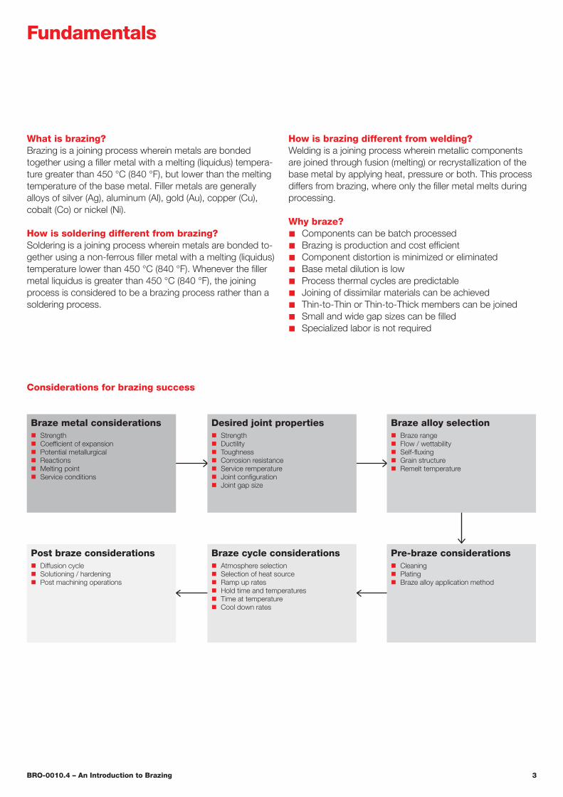
Considerations for brazing success
Braze metal considerations Strength Coefficient of expansion Potential metallurgical Reactions Melting point Service conditions
Desired joint properties Strength Ductility Toughness Corrosion resistance Service remperature Joint configuration Joint gap size
Pre-braze considerations Cleaning Plating Braze alloy application method
Braze cycle considerations Atmosphere selection Selection of heat source Ramp up rates Hold time and temperatures Time at temperature Cool down rates
Post braze considerations Diffusion cycle Solutioning / hardening Post machining operations
Braze alloy selection Braze range Flow / wettability Self-fluxing Grain structure Remelt temperature
Fundamentals
BRO-0010.4 – An Introduction to Brazing 4
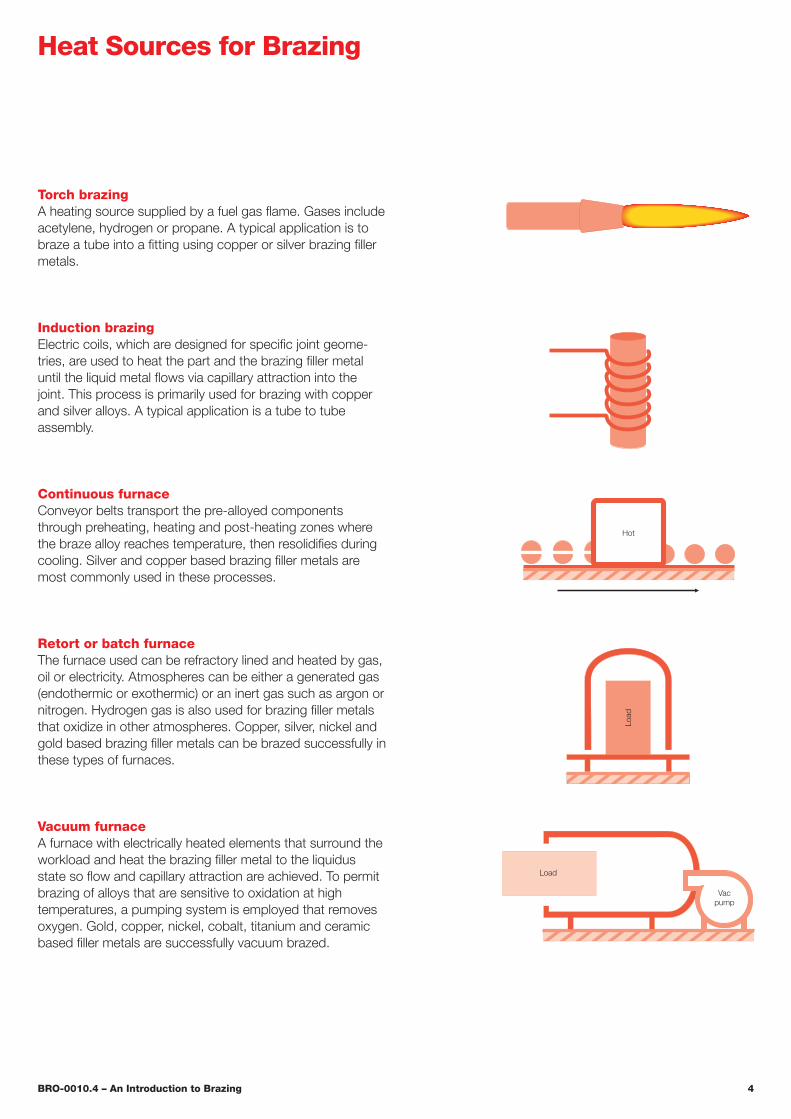
Torch brazingA heating source supplied by a fuel gas flame. Gases include acetylene, hydrogen or propane. A typical application is to braze a tube into a fitting using copper or silver brazing filler metals .
Hot
Load
Load
Vacpump
Heat Sources for Brazing
Vacuum furnaceA furnace with electrically heated elements that surround the workload and heat the brazing filler metal to the liquidus state so flow and capillary attraction are achieved. To permit brazing of alloys that are sensitive to oxidation at high temperatures, a pumping system is employed that removes oxygen. Gold, copper, nickel, cobalt, titanium and ceramic based filler metals are successfully vacuum brazed .
Induction brazingElectric coils, which are designed for specific joint geome-tries, are used to heat the part and the brazing filler metal until the liquid metal flows via capillary attraction into the joint. This process is primarily used for brazing with copper and silver alloys. A typical application is a tube to tube assembly .
Continuous furnaceConveyor belts transport the pre-alloyed components through preheating, heating and post-heating zones where the braze alloy reaches temperature, then resolidifies during cooling. Silver and copper based brazing filler metals are most commonly used in these processes.
Retort or batch furnaceThe furnace used can be refractory lined and heated by gas, oil or electricity. Atmospheres can be either a generated gas (endothermic or exothermic) or an inert gas such as argon or nitrogen . Hydrogen gas is also used for brazing filler metals that oxidize in other atmospheres. Copper, silver, nickel and gold based brazing filler metals can be brazed successfully in these types of furnaces.

BRO-0010.4 – An Introduction to Brazing 5
Braze filler metal base material
Base material Nickel (Ni) Cobalt (Co) Silver (Ag) Gold (Au) Aluminum (Al) Copper (Cu)
Braze range 927 – 1205 °C1700 – 02200 °F
1175 – 1245 °C2150 – 2275 °F
620 – 980 °C1150 – 1800 °F
890 – 1230 °C1635 – 2250 °F
570 – 620 °C1060 – 1150 °F
705 – 1150 °C1300 – 2100 °F
Maximum useful service temperature
980 °C1800 °F
1040 °C1900 °F
370 °C700 °F
800 °C1475 °F
150 °C300 °F
370 °C700 °F
Applications n Alloy steels n Carbon steels n Copper alloys n Stainless steels n Nickel / cobalt alloys
n Cobalt alloys n Alloy steels n Carbon steels n Cast iron n Copper alloys n Nickel alloys n Stainless steels n Tool steels
n Alloy steels n Carbon steels n Copper alloys n Nickel / cobalt Alloys n Stainless steels n Tool steels
n Aluminum alloys
n Alloy steels n Carbon steels n Cast iron n Copper alloys n Nickel alloys n Stainless steels n Tool steels
Brazing methods/ atmospheres
n Dissociated ammonia n Hydrogen n Induction n Inert gas n Torch n Vacuum
n Hydrogen n Inert gas n Vacuum
n Dip n Dissociated ammonia n Fuel gas (carburizing/ decarburizing) n Hydrogen n Induction n Inert gas n Torch n Vacuum
n Inert gas n Vacuum
n Dip n Torch n Resistance n Vacuum
n Dip n Dissociated ammonia n Fuel gas (carburizing/ decarburizing) n Hydrogen n Induction n Inert gas n Torch n Vacuum
Wide gapcapability
Yes1.5 mm0.06 in.
Moderate0.6 mm0.025 in.
No No Moderate0.6 mm0.025 in.
No
Costs Moderate Moderate to high High market price Ag
Very high market price Au
Low Low
ASTMdesignation
BNi BCo BAg BAu BAlSi BCu
Braze Filler Metals

BRO-0010.4 – An Introduction to Brazing 6
Braze filler metal alloying elementsVarious elements are added to braze filler metals . The purpose and behavior of these alloying elements are listed below .
Nickel (Ni) Provides desirable high temperature chemical and physical properties. Very compatible with other alloying elements .
Cobalt (Co) Has physical behavior that is very similar to nickel and can be freely substituted for a major portion of the nickel in any specific formulation. When added to nickel, it provides increased solubility, higher service temperature and increased matrix strength .
Manganese (Mn) Functions as a melting temperature suppressant.
Boron (B) Acts as a temperature suppressant, aids wetting through self-fluxing of oxides and contributes to high temperature strength and oxidation resistance. As an effective deoxidizer, boron provides additional joint strength and corrosion resistance . Can be readily diffused from the braze deposit.
Silicon (Si) Behaves in much the same manner as boron . Primary duty is as a self-fluxing temperature suppressant. Secondary role is as a grain refiner affording strength, oxidation resistance and corrosion resistance to the joint at elevated temperatures. Cannot be readily diffused.
Iron (Fe) Appears to promote flow of the molten alloy and tends to make a sounder, tougher joint. Acts as a barrier to the migration of base metal elements into the braze joint.
Chromium (Cr) Enhances both joint strength and high temperature oxidation resistance.
Tungsten (W) Improves matrix strength and corrosion resistance . Through matrix solid solutioning, it aids in resisting deformation under high temperature stressing.
Aluminum (Al) Is both a grain refiner and oxidation resis-tant additive .
Copper (Cu) Improves wetting and molten metal flow characteristics, benefiting corrosion resistance .
Molybdenum (Mo) Can combine with carbon to form complex carbides that enhance joint strength and effectively controls rapid grain growth. Also stiffens the matrix against plastic deformation.
Carbon (C) This element is included in the generally ac-cepted impurities and minor constituents of the alloying ele-ments. Therefore, its inclusion is kept to a minimum. Carbon acts to lower the melting range .
Titanium (Ti) and Niobium (Nb) Appear to form carbides in the presence of excess carbon, providing added high temperature strength without noticeable side effects. In solid solutions, they increase the corrosion resistance of the matrix .
Germanium (Ge) Has the ability to lower the melting temperature and toughen the joint. It is often recognized microscopically as a finely distributed nodular phase.
Rare Earths of Lanthanum (La), Yttrium (Y), Neo-dymium (Nd), Praseodymium (Pr) and Cerium (Ce) are normally added to the melt as misch metal to promote out-gassing. In the alloy, they enhance oxidation resistance, pro-mote grain refinement, increase fluidity and increase joint ductility .
Typical brazing temperature ranges for various filler metals
°C °F 1370 2500
1260 2300
1150 2100
1085 1985
925 1700
815 1500
705 1300
600 1115
480 900
370 700
BrazeSolder
> 450 °C (> 840 °F)
< 450 °C (< 840 °F)
Gold
Cobalt
Nickel
Copper
Aluminum
Silver
Iron
Braze Filler Metals

BRO-0010.4 – An Introduction to Brazing 7
Available forms of braze filler metals
Braze products can be purchased in a variety of forms. Where available, customers can choose the form that is most convenient and efficient for their particular production needs.
Braze powder is produced by a process that generates clean, dense, spherical and dry particles. Each particle contains precise amounts of all the elements of a particular alloy and the powders are uniform and homogeneous .
Braze paste is composed of one or more braze alloy powders and a neutral, flux-free binder . The binder content ranges between 10 and 14 percent by weight, which results in a consistent, easily extruded braze paste. Binders may be water or organic based, pro-ducing pastes that are slow drying or fast drying. Syringes, cartridges and bulk packs are available .
Braze tape is manufactured by casting a uniform layer of braze alloy and a binder wound in rolls for ease of handling. The tapes are made to order with a specified thickness and width suitable for the component to be brazed. Adhesive can be applied to one or both sides of the tape.
Braze preforms are custom shapes cut from braze tape that are easy to apply for brazing . The adhesive backing will hold the preforms in place during assembly and brazing of component parts.
Braze foil is a flexible material that contains no binders or fluxes and can be as thick as 0 .06 mm (0 .0025 in .) . Foil can be cut into shapes and resistance tacked (spot welded) into place prior to assembly or brazing of components. Several sheets of foil can be used for added thickness .
Braze rod and wire are binder free and are commonly used in torch or induction brazing applications. Rod and wire materials are typically available in diameters from 0.8 to 9 .5 mm (0 .3125 to 0 .375 in .) . Cored forms of these products may also contain flux materials .
A photomicrograph of Amdry™ 805 etched with an aqueous, 10% potassium hy-droxide solution . Amdry™ 805 is an iron-based braze filler metal from Oerlikon Metco designed as a cost-effective, high-strength solution for stainless steel heat exchangers .
Braze Filler Metals

BRO-0010.4 – An Introduction to Brazing 8
Braze filler metal application by base material
Brazing filler metal Base material of component
Alu
min
um a
nd
alum
inum
allo
ys
Car
bon
stee
l and
lo
w a
lloy
stee
ls
Cas
t iro
n
Cer
amic
s
Cob
alt a
nd
coba
lt al
loys
Cop
per
and
copp
er a
lloys
Mag
nesi
um a
ndm
agne
sium
allo
ys
Nic
kel a
ndni
ckel
allo
ys
Sta
inle
ss s
teel
Tita
nium
and
titan
ium
allo
ys
Tool
ste
els
Aluminum based[BAlSi]
Cobalt based[BCo]
Copper (pure)[BCu]
Copper phosphorus[BCuP]
Copper-zinc[BCuZn]
Iron based
Gold based[BAu] 1
Magnesium based[BMg]
Nickel based[BNi]
Silver based[BAg]
Titanium based
1 applications are limited
Braze Filler Metals

BRO-0010.4 – An Introduction to Brazing 9
Braze Joint Design
Joint properties Shear strength The ability to resist the angular defor-
mation, calculated as the sideways displacement of two adjacent planes divided by the distance between them.
Butt tensile strength The ability to resist a force ap-plied perpendicular to a given plane without rupturing.
Stress rupture A fracture caused as a result of repeat-ed physical strain.
Hardness The ability of a material to resist scratching, abrasion, indentation or machinin g, as measured by a specifically chosen method or standard.
Corrosion resistance The ability of a material to resist attack resulting from environmental, chemical or galvanic action .
Oxidation resistance The ability of a material, particu-larly a metal, to resist reaction with oxygen, which can cause a loss of structural integrity resulting from the for-mation of undesirable oxide compounds.
Microstructure The composition and microscopic structure of a material, as studied using metallographic methods .
Joint configuration The design and shape of the joint chosen to join members that will meet or exceed structural requirements in service. Types of joint configu-rations include lap, butt, tee, tubing, tube thru plate and scarf (see section on Joint configuration) .
Calculating the length of lap for flat jointsFormulaX = (Y – T – W) / L
WhereX = Length of lap areaY = Safety factor desiredT = Tensile strength of weakest memberW = Thickness of weakest memberL = Shear strength of brazing filler metal
X
W
ExampleWhat length of lap is needed to join 1.5 mm annealed Monel sheet to a metal of equal or greater strength?
SolutionY = 2 (desired safety factor for the assembly)T = 482 .6 MPa (tensile strength of annealed Monel sheet)W = 1.5 mmL = 172 .4 MPa (arbitrary value for the average brazing
filler metal)
ResultX = (2 – 482.6 – 1.5) / 172.4 = 8.4 mm (length of lap)

BRO-0010.4 – An Introduction to Brazing 10
Joint configuration
Joint type Flat parts Tubular parts (cutaway)
Butt joint
Lap joint
Butt-lapp joint
Scarf joint
Tee joint
Maximumbonding surface
Braze Joint Design

BRO-0010.4 – An Introduction to Brazing 11
Capillary braze actionCapillary attraction: The force by which a liquid, in this case the braze filler metal, in contact with a solid is distribut-ed between closely fitting adjacent surfaces. The ability of the filler metal, in a liquid state, to pull its mass along the sol-id contact surfaces between two components permits braz-ing of blind joints.
Wetting in braze joints
Capillary force enhanced brazing Filler material in place
Before brazing
During brazing
After brazing
Braze alloy deposit Good wetting condition
Braze alloy deposit on a prepared metalsurface (prior to brazing)
Q < 90°
The conditions are present to allow the brazealloy to spread out onto the base metal
Poor, non-wetting condition De-wetting condition
Q = 90°
Poor conditions during brazing prohibit thealloy from wetting
Q > 90°
Braze conditions were so poor that the alloypulled up and away from the base metal
Brazing

BRO-0010.4 – An Introduction to Brazing 12
Typical heating and cooling cycle for furnace brazing
1 . Hold #1: At 150 to 260 °C (300 to 500 °F) for 10 to 15 minutes. This allows solvents or water in the paste or binder vehicle to outgas from the braze alloy deposit.
Helps to prevent eruptions (holes) in the brazed deposit
Restore the atmosphere quality which can degrade from gasses
2 . Hold #2: At approximately 540 °C (1000 °F) for 10 to 15 minutes. This allows the organics (not liquids) in the braze vehicle sufficient time to become gaseous and to be removed through the pumping system.
Allows time for the quality of the furnace atmosphere to return
3 . Hold #3: At 10 to 38 °C (50 to 100 °F) below braze alloy solidus temperature.
Stabilization hold for a minimum of ten minutes or until part thermocouples have reached set Delta T
Ramp Up Rate: Heat as fast as possible (without part dis-tortion or compromise of metallurgical properties) to the braze temperature to prevent liquation of the braze alloy.
4 . Hold #4: Typically, a hold time of 0 to 60 minutes at the braze temperature allows sufficient time for the alloy to melt and flow into the joint. Ramp Down Rate: Slowly reduce the temperature to al-low liquid alloy to solidify in place. Begin to quench below the solidus temperature of the braze alloy.
5 . Hold #5: A diffusion hold of two to four hours at 1065 to 1150 °C (1950 to 2100 °F) will allow boron to diffuse and raise remelt temperature of the braze alloy. Cooling Ramp: Use a rate that will control distortion, meet required metallurgical properties and production needs.
1
2
3
4
5
Cooling
Cooling
Alternatediffusion cycle
Brazing

BRO-0010.4 – An Introduction to Brazing 13
Vapor pressure curves for vacuum brazing
Temperature °C
Boiling point all substances at 1 Atmosphere
105
104
103
101
1
10-1
10-2
10-3
10-4
10-5
10-6
10-7
10-8
10-9
10-10
10-11
10-12
10-13
10-14
10-15
102 105
104
103
101
1
10-1
10-2
10-3
10-4
10-5
10-6
10-7
10-8
10-9
10-10
10-11
10-12
102
108
107
106
Pre
ssur
e m
m o
f Hg
Pre
ssur
e m
icro
ns
020
040
060
080
0
1000
1200
1400
1600
1800
2000
2200
2400
2600
2800
3000
As4
Hg
Bi
Al
Mg
Pb
Zn
Cd
Ni
Ca Mn
CuFe
Co
Cr Pt
Zr
W
C
Ti
Mo
Ta
Under reduced pressure, the boiling point of metals is lowered. For combinations of temperatures and pressures lying left of the curve, the metal is a liquid or solid. To the right of the curve it is a vapor.
Brazing

BRO-0010.4 – An Introduction to Brazing 14
Braze joint morphology
base metal
base metal
Amorphous matrix
Non-continuous dendrites
Solid solution loops
Gap
Alloy diffusion
base metal
Solid solutioning loops
Eutectic matrix
Primary idiomorphic crystals
Fillet
Eutectic
Boride / silicide chains
Gap
base metal
Alloy diffusion
Brazing

BRO-0010.4 – An Introduction to Brazing 15
Supplementary Processing Elements
Braze procedure
1. Cleaning Chemical Mechanical Nickel plate Furnace clean Hydrogen fluoride
2. Assembly Placement weld
f Tack f Spot f Resistance
Fixturing
3. Alloy application Cements
f Product of the paint industry f Temporary binder– Poly isobutylene– Acryloid– Polyvinyl / gum / cellulose / parahydroxybenzonate
f Burns off at 480 °C (900 °F) Pastes
f Product of the food industry f Long term powder suspension f Burns off at 480 °C (900 °F) f Water soluble or organic base
4. Stop-off application Deterrent to flow Ceramic plus vehicle
f Alumina f Calcium carbonate f Titania f Boron nitride f Poly isobutylene f Lacquer
5. Thermal cycle Furnace bake-out Thermocouple / temperature
measurement Preheat Braze time / temperature Cool down
6. Post treatment Thermal Chemical cleaning Mechanical cleaning Mechanical dimensioning
7. Inspection Non-destructive
f Visual f X-ray f Ultrasonic f Liquid penetrant (ultraviolet)
Destructive f Tensile f Hardness f Metallography
Ventilation Toxic metals Fumes / vapors Solvents
Cleanliness Base metal Work area
Safety
Cleaning AssemblyAlloy
applicationStop-off
applicationThermal
cyclePost
treatment Inspection
1 2 3 4 5 6 7
Equipment Furnaces Atmospheres Tig welder Laser Induction Torch
Base metal recognition Material type Plating
Filler metal identification Certification SDS (Safety Data Sheet)

BRO-0010.4 – An Introduction to Brazing 16
Brazing Tips
ProblemThe braze alloy balls up and fails to wet the surface or run into the joint.
Possible solutions1. Improve cleaning methods to insure removal of
con taminants .2 . Clean and roughen the surface by grit blasting .3 . Grind or machine off surfaces of cold-drawn and cold-
rolled bar stock .4. Improve protective atmosphere quality.5. Change position of the part to encourage the braze alloy
to run into the joints.
ProblemCapillary action doesn't occur even though the braze alloy melts and forms a fillet .
Possible solutions1 . Increase time at heat .2. Loosen or tighten the joint fit-up.3. Increase braze temperature.4. Clean mating parts more thoroughly.5. Check for improper or insufficient cleaning.6. Check for contamination in the joint from cements or gels
used to apply the filler metal.7 . Check for voids in the fillet .8. Check for bad fit-up of mating parts during assembly.
ProblemThe braze alloy flows away from the joint rather than into it.
Possible solutions1. Check base metal properties for elements that oxidize
and inhibit braze flow .2. Check cleaning process.3. Compare actual size of the joint gap to the size
recommended for the braze alloy being used .4. Remove any burrs at the edge of the joints or any other
obstacles which stop the flow of the alloy.5. Try providing a reservoir for better placement of the alloy
at the joint.6. Try using a stop-off to retard the flow of the alloy away
from the joint area.7. Try changing the alloy form to pre-place the braze alloy
into the joint area.
ProblemThere is indication the alloy melted but there was no flow .
Possible solutions 1. Look for surface contaminants left from poor cleaning.2. If possible, clean the filler metal (wipe clean wires, rod and
foil forms of alloy) .3. Increase braze temperature or time at heat.4. Check the atmosphere quality and improve it, if
necessary .5. Check if braze gap is too large or too small.
Problem A tight fitting joint opens up during brazing.
Possible solutions1. Check for high coefficient of expansion.2. Check for incompatible expansion between dissimilar
metals .3 . Check for release of base metal stresses during heat
cycle .4. Check for poor support of the components.5. Check for a press fit that is too tight and stretches the
outer component beyond its elastic limit.6. Check for fixturing that constrains the part too much.7. Try adjusting the heating and cooling rates to allow for dif-
ferences in expansion.8. Try lighter weight fixtures that support well but do not
constrain the components.
ProblemBraze splatters appear around the braze joint.
Possible solutions1 . Try slowing the heating rate between 150 – 540 °C
(300 – 1000 °F) and use stabilizing holds to help remove liquids from binders used to apply the filler metals.
2. Try changing the form of the alloy, if possible.3 . Try to control cooling from 35 – 95 °C (100 – 200 °F) from
the braze temperature before quenching the parts.

BRO-0010.4 – An Introduction to Brazing 17
Problem The joint appears starved or lacking alloy in areas.
Possible solutions 1. Check the braze alloy deposit to be sure there is sufficient
material to fill the joint.2. Make sure the alloy is securely attached to the part right
up to the melting temperature.3 . Be sure the filler metal has not been blown off by quench
gas while it is still liquid from the brazing temperature.4. Check if the braze gap is too large.5. Check the vapor pressure chart to see if a component in
the braze alloy was vaporized, leaving the alloy unable to melt or flow .
Oerlikon Metco’s extensive portfolio of braze filler al-loys are available as powder or paste. To meet spe-cific customer requirements, we provide customized tapes, preforms, binderless braze ribbon and binder-less braze sheet. All of Oerlikon Metco’s braze prod-ucts are manufactured to exacting quality standards .
Brazing Tips

BRO-0010.4 – An Introduction to Brazing 18
Glossary of Brazing Terms
Aaggression / erosion Excessive alloying can lead to catastrophic effects during brazing. It is primarily a function of time and temperature. Surface dissolution and intergranular attack (IGA) are manifestations .
alloying An interaction between the base metal and filler metal where a minimal dilution of each occurs . This is identified by a migration of elements across the joint inter-face . Alloying, on a limited scale, is generally beneficial— often increasing joint strength above that obtained by simple wetting. However, it can, based upon chemical composi-tions, affect corrosion resistance .
arc brazing (AB) A brazing process in which the heat required is obtained from an electric arc .
as-brazed The condition of brazements after brazing and prior to any subsequent thermal, mechanical or chemical treatments .
automatic brazing Brazing with equipment which per-forms the brazing operation without constant observation and adjustment by a brazing operator. The equipment may or may not perform the loading and unloading of the work. See machine brazing .
Bbase material The material to be welded, brazed, sol-dered or cut . See also base metal and substrate .
base metal The metal to be welded, brazed, soldered or cut. The use of this term implies that materials other than metals are also referred to, where this is appropriate. See also base material and substrate .
base metal test specimens A test specimen composed wholly of base metal .
binder A liquid material used in the application of powders that cause the powder to compact and stay in place, even after the binder is removed during brazing .
blind joint A joint where no part of it is visible to view.
block brazing (BB) A brazing process in which the heat required is obtained from heated blocks applied to the parts to be joined.
bond A unifying force that holds things together .
braze A bond produced by heating an assembly to suitable temperatures and by using a filler metal having a liquidus above 450° C (840 °F) and below the solidus of the base metal . The filler metal is distributed between the closely fitted faying surfaces of the joint by capillary action.
braze welding A welding process variation in which a filler metal, having a liquidus above 450 °C (840 °F) and below the solidus of the base metal, is used. Unlike brazing, the fill-er metal is not distributed in the joint by capillary action.
brazeability The capacity of a metal to be brazed under the fabrication conditions imposed into a specific suitably designed structure and to perform satisfactorily in the intend-ed service .
brazement An assembly having component parts joined by brazing .
brazer One who performs a manual or semi-automatic brazing operation.
brazing (B) A group of welding processes which produces coalescence of materials by heating them to a suitable tem-perature and by using a filler metal having a liquidus above 450 °C (840 °F) and below the solidus of the base metal . The filler metal is distributed between the closely fitted laying surfaces of the joint by capillary action.
brazing alloy See preferred term brazing filler metal.
brazing filler metal The metal which fills the capillary gap and has a liquidus above 450 °C (840 °F) but below the soli-dus of the base materials .
brazing operator One who operates machine or automat-ic brazing equipment.
brazing procedure The detailed methods and practices including all joint brazing procedures involved in the produc-tion of a brazement. See joint brazing procedure.
brazing sheet Brazing filler metal in sheet form, which can be with or without a binder .
brazing technique The details of a brazing operation which, within the limitations of the prescribed brazing proce-dure, are controlled by the brazer or the brazing operator.
brazing temperature The temperature to which the base metal is heated to enable the filler metal to wet the base metal and form a brazed joint.

BRO-0010.4 – An Introduction to Brazing 19
brazing temperature range The temperature range within which brazing can be conducted .
Ccapillary action The force by which liquid, in contact with a solid, is distributed between closely fitted facing surfaces of the joint to be brazed or soldered.
cement A viscous liquid, of either a rubber or acrylic base, which acts as both a vehicle and a binder . It is mixed with any powdered filler metal to permit application with a brush, eyedropper, etc. It causes the metal to compact, holding it in place, even after it volatilizes.
clad brazing A metal sheet on which one or both sides are clad (coated) with brazing filler metal . Clad brazing is found most often in aluminum brazing .
copper brazing A term improperly used to denote brazing with copper filler metal. See preferred terms furnace brazing and braze welding .
corrosive flux A flux with a residue that chemically attacks the base metal. It may be composed of inorganic salts and acids, organic salts and acids or activated rosins or resins .
Ddew point The temperature at which water condenses out of an atmosphere for a given pressure.
differential thermal analysis (DTA) A test procedure for determining the solidus and liquidus temperatures of a material .
diffusion bonding See preferred terms diffusion brazing and diffusion welding .
diffusion brazing (DFB) A brazing process which pro-duces coalescence of metals by heating them to suitable temperatures and by using a filler metal of an in-situ liquid phase. The filler metal may be distributed by capillary attrac-tion or may be placed or formed at the faying surfaces. The filler metal is diffused with the base metal to the extent that the joint properties have been changed to approach those of the base metal. Pressure may or may not be applied.
diffusion heat treatment A thermal cycle, usually per-formed at 1065 to 1093 °C (1950 to 2000 °F) for two to four hours to cause migration of filler metal suppressants into the base metal. This effectively raises the remelt temperature and strengthens the joint.
Temperature (°F)
0
-5
-10
-15
-20
-25
-30
-35
-401550 1600 1650 1700 1750 1800 1850 1900 1950 2000
DTA
(mic
rovo
lts)
2050
Solidus1027 .2 °C(1881 °F)
Liquidus1055 °C(1931 °F)
Second heat cycle
Differential Thermal Analysis (DTA) Amdry 108 Two Cycle: 880 to 1100 °C @ 10 °C/min (1616 to 2012 °F @ 18 °F/min) in Argon
Glossary of Brazing Terms

BRO-0010.4 – An Introduction to Brazing 20
dip brazing (DB) A brazing process in which the heat re-quired is furnished by a molten chemical or metal bath . When a molten chemical bath is used, the bath may act as a flux. When a molten metal bath is used, the bath provides the filler metal .
Eelectric brazing See preferred terms resistance brazing and arc brazing .
erosion (brazing) A condition caused by dissolution of the base metal by molten filler metal resulting in a post-braze reduction in the thickness of the base metal .
eutectic (1) An isothermal reversible reaction in which a liquid solution is converted into two or more intimately mixed solids on cooling; the number of solids formed being the same as the number of components in the system. (2) An alloy having the composition indicated by the eutectic point on an equilibrium diagram . (3) An alloy structure of intermixed solid constituents formed by a eutectic reaction . Refer to Silver – Copper Constitutional Diagram, this page.
Ffeed side That external face of an intended joint to which the main reservoir of the filler metal is added prior to the braze operation.
filler metal The metal to be added in making a welded, brazed or soldered joint.
fillet A radiussed area of filler metal at the site where components are joined.
fissure A small crack-like discontinuity with only slight separation (opening displacement) of the fracture surfaces. The prefixes macro or micro indicate relative size.
flash The material which is expelled or squeezed out of a joint.
flaw A near synonym for discontinuity, but with an undesirable connotation .
flow brazing (FLB) A brazing process which produces coalescence of metals by heating them with molten, nonferrous filler metal poured over the joint until brazing temperature is attained. The filler metal is distributed in the joint by capillary attraction.
flowability The ability of molten filler metal to flow or spread over a metal surface.
flux Material used to prevent, dissolve or facilitate removal of oxides and other undesirable surface substances .
flux cover In metal bath dip brazing and dip soldering, a cover of flux over the molten filler metal bath .
freezing point See preferred terms liquidus and solidus.
furnace brazing (FB) A brazing process in which the parts to be joined are placed in a furnace and heated to a suitable temperature.
fusion The melting together of filler metal and base metal (substrate) or of base metal only, which results in coalescence .
Ggap See joint clearance.
gas brazing See preferred term torch brazing.
Hhard solder A term erroneously used to denote silver-base brazing filler metals .
heat-affected zone (HAZ) The region of the base metal that has been thermally altered as a result of welding, braz-ing, soldering or thermal cutting processes.
2000
17611600
1200
800
400
Tem
pera
ture
°F
100 % Ag0 % Cu
0 % Ag100 % Cu
1981B
A Solid &Liquid
C
Liquid
D
(Ag)α
Solid(Ag + Cu)
Solidus 1435 °F
LiquidusSolid &Liquid
(Cu)δ
E
72 % Ag28 % Cu
Composition
SILVER – COPPER CONSTITUTIONAL DIAGRAM
Glossary of Brazing Terms

BRO-0010.4 – An Introduction to Brazing 21
holding time In brazing and soldering, the amount of time a joint is held within a specified temperature range.
hot crack A crack that develops during solidification.
hydrogen brazing A term erroneously used to denote any brazing process which takes place in a hydrogen or hydro-gen-containing atmosphere.
Iinadequate joint penetration Joint penetration by the braze alloy that is less than specified.
incomplete fusion A condition where all of the braze filler metal in a joint did not melt.
induction brazing (IB) A brazing process in which the heat is obtained from the resistance of the work piece to in-duced electric current .
infrared brazing (IRB) A brazing process in which the heat is furnished by infrared radiation .
infrared radiation Electromagnetic energy with wave-lengths from 770 to 12,000 nanometers .
intergranular penetration The penetration of a filler met-al along the grain boundaries of a base metal .
Jjoint The junction of members or the edges of members which are to be joined or have been joined.
joint brazing procedure The materials, detailed methods and practices employed in the brazing of a particular joint.
joint clearance The distance between the mating surfac-es of a joint. In brazing, this distance can vary during the brazing process as a result of thermal expansion.
joint design The joint geometry together with the required dimensions .
joint efficiency The ratio of the strength of a joint to the strength of the base metal (expressed in percent).
joint geometry The shape and dimensions of a joint in cross-section prior to brazing.
Llack of fusion See preferred term incomplete fusion.
lap joint A joint between two overlapping members.liquation The separation of the low melting constituent(s) of an alloy from the remaining constituents, which is usually apparent in alloys having a wide melting range. The remain-ing deposit no longer brazes at the established melting temperature.
liquidus The lowest temperature at which a metal or an al-loy is completely liquid.
Mmachine brazing See preferred term mechanized brazing.
manual brazing A brazing operation performed and controlled completely by hand.
mechanized brazing Brazing with equipment which per-forms the brazing operation under the constant observation and control of a brazing operator. The equipment may or may not perform the loading and unloading of the work. Also see automatic brazing .
melting range The temperature range defined by the soli-dus and liquidus temperatures between which a brazing filler metal begins to melt and becomes completely fluid.
Nnoncorrosive flux A brazing flux which, in its original or residual form, chemically attacks the base metal . It usually is composed of rosin- or resin-base materials.
Pparent metal See preferred term base metal.
partial pressure In a closed system having a mixture of gases and vapors, the pressure a specific gas or vapor would exert if it occupied the entire volume of that mixture by itself. A gas is often added to a vacuum atmosphere to pre-vent the vaporization of a filler metal or base material without increasing moisture or contamination levels .
paste soldering filler metal A mixture of finely divided metallic solder with an organic or inorganic flux or neutral ve-hicle or carrier .
Glossary of Brazing Terms

BRO-0010.4 – An Introduction to Brazing 22
post heating The application of heat to an assembly after a brazing operation.
preform Brazing or soldering filler metal fabricated in a shape or form for a specific application.
preheat The heat applied to the base metal to achieve and maintain a preheat temperature.
preheat temperature A specified temperature that the base metal must attain in the brazing area immediately be-fore this operation is performed.
preheating The application of heat to the base metal immediately before brazing .
procedure The detailed process or method elements (with prescribed values or ranges of values) used to produce a specific result.
procedure qualification The demonstration that braze-ments made by a specific procedure can meet prescribed standards .
protective atmosphere A gas envelope surrounding the part to be brazed, with the gas composition controlled with respect to chemical composition, dew point, pressure, flow rate, etc. Examples are inert gases, combustible fuel gases, hydrogen and vacuum .
Rreaction flux A flux composition in which one or more of the ingredients reacts with a base metal upon heating to de-posit one or more metals.
reducing atmosphere A chemically active protective atmosphere which, at an elevated temperature, will reduce metal oxides to their metallic state. “Reducing atmosphere” is a relative term as an atmosphere may be reducing to one oxide but not to another oxide .
resistance brazing (RB) A brazing process in which the heat required is obtained from the resistance to electric cur-rent in a circuit of which the work is a part.
Ssalt-bath dip brazing A variation of the dip brazing process.
sandwich braze A brazed assembly of disimiliar materials where a preplaced shim, having a composition different than that of the filler metal, that serves as a transition layer to minimize thermal stresses .
self-fluxing alloys Certain materials that “wet” the sub-strate and coalesce when heated to their melting point, with-out the addition of a fluxing agent .
semiautomatic brazing Brazing with equipment which controls only the brazing filler metal feed . The advance of the brazing is manually controlled .
semiblind joint A joint in which one extremity of the joint is not visible .
silver soldering, silver brazing Nonpreferred terms used to denote brazing or soldering with a silver-base filler metal. See preferred terms furnace brazing, induction braz-ing and torch brazing .
skull The unmelted residue from a liquated filler metal .
solder A filler metal used in soldering which has a liquidus not exceeding 450 °C (840 °F) .
soldering (S) A group of processes that produces co-alesced materials by heating them to a suitable temperature using a filler metal having a liquidus not exceeding 450 °C (840 °F) and below the solidus of the base metals . The filler metal is distributed between the closely fitted faying surfaces of the joint by capillary action.
solidus The highest temperature at which a metal or alloy is completely solid.
step brazing The brazing of successive joints on a given part with filler metals of successively lower brazing tempera-tures so as to accomplish the joining without disturbing the joints previously brazed. A similar result can be achieved at a single brazing temperature if the remelt temperature of prior joints is increased by metallurgical interaction.
stopoff A material used on the surfaces adjacent to the joint to limit the spread of brazing filler metal while the filler metal is in a liquid state .
substrate The metal or material to be welded, brazed, soldered or cut .
Glossary of Brazing Terms

BRO-0010.4 – An Introduction to Brazing 23
Tthermocouple A device for measuring temperatures con-sisting of two dissimilar metals (the base metal and the ther-mocouple wire) which produce an electromotive force rough-ly proportional to the temperature difference between the ends of the hot and cold junctions.
torch brazing (TB) A brazing process in which the heat required is furnished by a fuel gas flame .
Vvacuum brazing A term used to denote various brazing processes which take place in a chamber or retort below atmospheric pressure.
Wweld brazing A joining method which combines resistance welding with brazing .
wetting The phenomenon whereby a liquid filler metal or flux spreads and adheres in a thin continuous layer on a properly prepared solid base metal surface.
wicking Flashing of the brazing filler metal out of the joint onto adjacent areas, or the flow of brazing filler metal up the joint walls from a pre-placed deposit.
workpiece A part or an assembly that is brazed.
A photomicrograph of a typical brazed tee-joint. The braze filler metal was originally placed on one side of the joint and flowed through via capillary action, properly filling the small gap area and forming a smooth fillet on each side of the joint. Silicides can be seen as a result of the silicon contained in the braze filler metal used (Amdry™ 105) .
Glossary of Brazing Terms

BRO-0010.4 – An Introduction to Brazing 24www.oerlikon.com/metco [email protected]
Braze MaterialsAdvanced Technology Solutions and Services
Perfect solutions through optimum materials and innovative technologiesOerlikon Metco is a global leader in surface engineering solutions and services offering:
A broad range of thermal spray, thin film, laser cladding and other advanced surface technology equipment and materials
Integrated systems Specialized coating and surface
enhancement services Manufactured components for the
turbine, automotive and other industries
Customer support services
Oerlikon Metco provides a comprehensive manufacturing, distribution and service network, catering to aviation, power generation, automotive and other strategic growth industries .
To take control of your surface engineering challenges, contact your Oerlikon Metco sales office, visit our web site at www .oerlikon .com/metco or e-mail us at [email protected] .
About Oerlikon MetcoOerlikon Metco enhances surfaces that bring benefits to customers through a uniquely broad range of surface technologies, equipment, materials, services, specialized machining services and components. The surface technologies such as Thermal Spray, Thin Film, Plasma Heat Treatment and Laser Cladding improve the performance and increase efficiency and reliability. Oerlikon Metco serves industries such as aviation, power generation, automotive, oil & gas, industrial and other specialized markets and operates a dynamically growing network of more than 50 sites in EMEA, Americas and Asia-Pacific. Oerlikon Metco, together with Oerlikon Balzers, belongs to the Surface Solutions Segment of the Switzerland-based Oerlikon Group.
Information is subject to change without prior notice.