An Introduction to Architectural Design: Theatres and ...
26
© J. Paul Guyer 2014 1 J. Paul Guyer, P.E., R.A. Paul Guyer is a registered civil engineer, mechanical engineer, fire protection engineer and architect with 35 years of experience designing buildings and related infrastructure. For an additional 9 years he was a principal staff advisor to the California Legislature on capital outlay and infrastructure issues. He is a graduate of Stanford University and has held numerous national, state and local offices with the American Society of Civil Engineers, Architectural Engineering Institute and National Society of Professional Engineers. An Introduction to Architectural Design: Theatres and Concert Halls, Volume 4
Transcript of An Introduction to Architectural Design: Theatres and ...

© J. Paul Guyer 2014 1
J. Paul Guyer, P.E., R.A. Paul Guyer is a registered civil engineer, mechanical engineer, fire protection engineer and architect with 35 years of experience designing buildings and related infrastructure. For an additional 9 years he was a principal staff advisor to the California Legislature on capital outlay and infrastructure issues. He is a graduate of Stanford University and has held numerous national, state and local offices with the American Society of Civil Engineers, Architectural Engineering Institute and National Society of Professional Engineers.
An Introduction to Architectural Design: Theatres and Concert Halls, Volume 4

© J. Paul Guyer 2014 2
CONTENTS
1. INTRODUCTION
2. THEATER LIGHTING
3. SCENERY AND SOFTGOODS
4. RIGGING AND STAGE MECHANISMS
(This publication is adapted from the Unified Facilities Criteria of the United States government which are in the public domain, have been authorized for unlimited distribution , and are not copyrighted.) (This publication is the fourth in a series under editorial development dealing with the design of theatres and concert halls.)
© J. Paul Guyer 2014 3
1. INTRODUCTION. This section contains collected technical information and
equipment requirements for the construction and operation of Music and Drama Centers
(MDC). This section is intended to give the designer and reviewing agencies an
understanding of the scope of equipment and detailed study needed to produce a fully
functional performance facility. It is not to be considered a substitute for technical
expertise essential to project development. However, project participants will find it a
useful reference in making statements of functional requirements and as a budget
preparation checklist.
© J. Paul Guyer 2014 4
2. THEATER LIGHTING.
2.1 OVERSTAGE POSITIONS. Pipes and bridges extend the width of the acting area in
pairs 7-10 feet apart up and down-stage for the full depth of the stage, and are
adjustable in elevation. Instruments are clamped in place, adjusted in place, and
powered through pigtail interlocking plugs to cable carried in raceway or tied to the
pipes. The cables run to an interconnect panel or patch-board on stage. Bridges permit
maintenance and manual adjustment without lowering the entire line of instruments and
without the use of ladders. Bridges are recommended for the most-used first pipe
“teaser” position and for the cyclorama backdrop position, where large quantities of
several kinds of instruments are common. Bridges extend to the fly gallery for access,
and are invaluable where box sets interfere with lowered pipes.
2.2 SIDESTAGE POSITIONS. Pipe booms are floor supported and ladder frames are
hung from the gridiron. The fly gallery and wall-mounted ladders may also be utilized, as
well as tormentor locations just behind the proscenium arch. One sidestage position on
each side of the stage is generally associated with each overhead pair of pipes.
2.3 STAGE FLOOR POSITIONS. Footlight troughs, cyclorama pit and deck boxes
called “floor pockets” accept sub-surface instruments for washlighting scenery and
drops; footlights are rarely used to light actors but are commonly used to light scenery.
There may also be individual instruments on portable stands.
2.4 PROSCENIUM POSITIONS. Slots alongside and above the proscenium on the
house side contain specials, wash, strip and spotlights in proximity to a personnel
ladder giving access to the overhead catwalk.
2.5 SIDEWALL POSITIONS. Vertical slots in the house walls or surface-mounted arms
carry spotlights essential for down-stage and forestage lighting.

© J. Paul Guyer 2014 5
2.6 CEILING POSITIONS. Catwalks at or above the house ceiling carry the bulk of front
lighting. They extend wall to wall. Critical dimensions are incident angle to the actor’s
face, distance of throw and angle of adjustable aim. Frontlights must be adjustable in
place from a technicians’ catwalk, and each spotlight must have a clear shot at the
whole stage.
2.7 BALCONY POSITIONS. Supplemental spotlighting is sometimes mounted on
fascias. The mount must have a pan to catch dropped filters and burst lamps.
Electricians also stand in the pan to adjust the spotlights.
2.8 FOLLOWSPOTS AND PROJECTORS. At least two instruments per booth or
platform is recommended. One center position may be augmented by one at each side.
Booths may be shared with film projectors for scenic images. An incident angle of 30-
35° to the leading edge of stage may in some cases permit movie projection on an
elevated screen. However, a separate film projection booth under the balcony or at the
back aisle is preferred.
2.9 LIGHTING CONTROL SYSTEMS. With the possible exception of house and
worklight autotransformer dimming from a position on stage, theater lighting makes use
of indirect electronic dimming controls operated from a small console in

© J. Paul Guyer 2014 6
Figure 1
Ceiling and sidewall slots

© J. Paul Guyer 2014 7
Figure 2
Follow spot elevation/four spot booth plan
© J. Paul Guyer 2014 8
Figure 3
Power center distribution
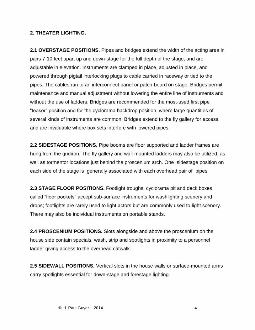
or behind the house. The remotely controlled dimmer bank is normally located in low-
value space under or alongside the house and between the control center and patch
panel. It is preferably nearer the patch panel to minimize highload wiring, but the
location of power service entry of 300-800 KVA to the dimmers may rule the choice. The
bank needs no access during performance, but the patch panel is located on or near
stage, again to minimize load-circuit wiring to the lighting positions. The patch panel
requires continuous access from the stage. Low-voltage control circuits activate the
dimmers which feed load circuits selected at the patch panel and into which circuits the
lighting instruments are plugged. A more recent and economical development is the
dimmer-per-circuit system. The interconnect (patch panel) function takes place at the
control center in low-voltage circuitry. Dimmers are installed in racks in or adjacent to
the stagehouse, one dimmer per loaded circuit into which instruments are selectively
plugged. Remember that dimmers make noise and should be isolated.

© J. Paul Guyer 2014 9
2.10 CONTROL CENTER EQUIPMENT. Controls include manual and automatic preset
potentiometers, or memory systems, or both. Power levels are set manually as the
lighting plot is developed. These are recorded when satisfactory and a fade-duration
established for cross fading from one scene to the next. The operator can manually set
the levels and durations during performance, activating the sequence on cue, or the
entire plot can be fed into a memory system that operates the cues and displays the
status of the plot for on-the-spot adjustments. Except in very small systems the memory
controls are less expensive, more capable, and therefore preferred. In any case, house
lights, work lights and lecture lights are separately controlled to avoid disturbing console
setups. Touring groups often travel with their own lighting equipment, including controls,
and are provided a power takeoff and company switch in the stagehouse. This is
another reason for careful consideration of power service entrance location and
selection of the most common compatible system interconnections to enable use of the
facility’s control center.
2.11 POWER CONSUMPTION: By its very nature, stagelighting power demand tends
to be related to the acting area dimensions, as is the number of in-or behind the house.
The remotely controlled dimmer bank is normally located in low-value space under or
alongside the house and between the control center and patch panel. It is preferably
nearer the patch panel to minimize highload wiring, but the location of power service
entry of 300-800 KVA to the dimmers may rule the choice. The bank needs no access
during performance, but the patch panel is located on or near stage, again to minimize
load-circuit wiring to the lighting positions. The patch panel requires continuous access
from the stage. Lowvoltage control circuits activate the dimmers which feed load circuits
selected at the patch panel and into which circuits the lighting instruments are plugged.
A more recent and economical development is the dimmer-per-circuit system. The
interconnect (patch panel) function takes place at the control center in low-voltage
circuitry. Dimmers are installed in racks in or adjacent to the stagehouse,

© J. Paul Guyer 2014 10
Figure 3
Powr center distribution
one dimmer per loaded circuit into which instruments are selectively plugged.
Remember that dimmers make noise and should be isolated.
2.12 CONTROL CENTER EQUIPMENT. Controls include manual and automatic preset
potentiometers, or memory systems, or both. Power levels are set manually as the
lighting plot is developed. These are recorded when satisfactory and a fade-duration
established for cross fading from one scene to the next. The operator can manually set
the levels and durations during performance, activating the sequence on cue, or the
entire plot can be fed into a memory system that operates the cues and displays the
status of the plot for on-the-spot adjustments. Except in very small systems the memory
controls are less expensive, more capable, and therefore preferred. In any case, house
lights, work lights and lecture lights are separately controlled to avoid disturbing console
setups. Touring groups often travel with their own lighting equipment, including controls,
and are provided a power takeoff and company switch in the stagehouse. This is

© J. Paul Guyer 2014 11
another reason for careful consideration of power service entrance location and
selection of the most common compatible system interconnections to enable use of the
facility’s control center.
2.13 POWER CONSUMPTION. By its very nature, stagelighting power demand tends to
be related to the acting area dimensions, as is the number of in-struments needed. It is
unwise to underestimate potential connected load in sizing the service. Common
practice is to apply a factor of 80% to the total dimmer capacity, but this should be
carefully considered. (N.B., 50% to 80% for dimmer-per-circuit systems). Planners must
ask themselves, does installed capacity take into account likely future growth (it always
grows) and the arrival of a road show with super power amplifiers and motorized
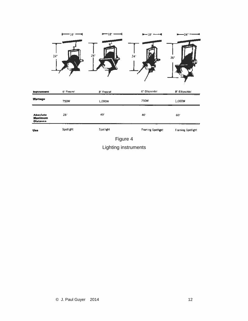
devices as well as lightingequipment. The sizes and quantities of stage lighting
equipment are determined primarily by the net stage area and secondarily by the type of
use.
© J. Paul Guyer 2014 12
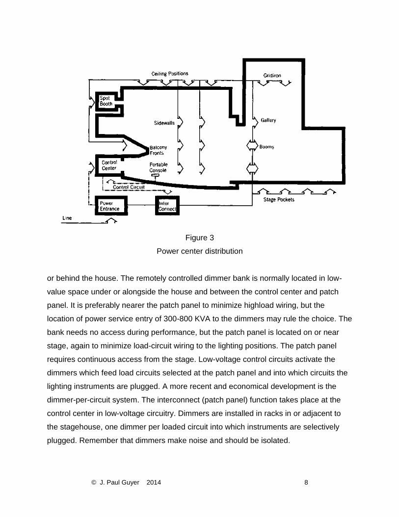
Figure 4
Lighting instruments
© J. Paul Guyer 2014 13
Table 1
Stage lighting requirements

© J. Paul Guyer 2014 14
Table 1 (continued)
Stage lighting requirements

© J. Paul Guyer 2014 15
3. SCENERY AND SOFTGOODS. The topic of stage dressing and sets is discussed
elsewhere in terms of its influence on stage shape, vision criteria, movement, sound
absorption and production activities—in short, it relates to many functional requirements
of theater design primarily because it is an indeterminate element of the artist’s
stagecraft. This discussion seeks only to ensure free ‘reign to his creativity’. From this
viewpoint, the major concern is to define adequate space, built-in mechanisms, lighting,
safety provisions and organization to facilitate set construction. and use. Draperies and
softgoods, however, must be either furnished or built custom fit, and merit discussion
here.
3.1 HOUSE CURTAINS. The major proscenium drape was traditionally an ornate
biparting curtain. It is often of heavy opaque material to muffle preparations on stage as
the audience is being seated. It signals the beginning and end of major sections, the
points at which house lights are lowered or raised and the audience is returned to “the
real world”. Modern practice installs the house curtain on the first pipe or set of rigging,
enabling it to be drawn both vertically aloft and horizontally on a traveller. Before
performance, it is usually lighted with “curtain warmers”.
3.2 TEASER OR HEADER. The second pipe holds the foremost border behind the
house curtain. It forms the apparent frame during performance. The proscenium may be
higher, and curved or splayed for acoustic purposes, while the teaser sets the initial
scale of audience/performer contact. It may be moved up or down, and hides the
lighting bridge or pipe immediately behind it.
3.3 TORMENTORS OR LEGS. The third pipe holds the principal legs or side masks
that can be moved on or offstage to set the width of the opening. In fact, both
tormentors and teaser can be soft fabric draperies, wood or steel frames covered with
fabric or solid panel construction. The stretched fabric may be chosen for its
appearance, ability to assume a particular shape, or its ability to screen temporary or
permanent loudspeakers. It is usually required for trimming to a shaped music shell;
some. shells work better with solid panel masks. Heavy tormentors can be mounted on
© J. Paul Guyer 2014 16
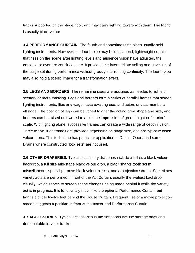
tracks supported on the stage floor, and may carry lighting towers with them. The fabric
is usually black velour.
3.4 PERFORMANCE CURTAIN. The fourth and sometimes fifth pipes usually hold
lighting instruments. However, the fourth pipe may hold a second, lightweight curtain
that rises on the scene after lighting levels and audience vision have adjusted, the
entr'acte or overture concludes, etc. It provides the intermediate veiling and unveiling of
the stage set during performance without grossly interrupting continuity. The fourth pipe
may also hold a scenic image for a transformation effect.
3.5 LEGS AND BORDERS. The remaining pipes are assigned as needed to lighting,
scenery or more masking. Legs and borders form a series of parallel frames that screen
lighting instruments, flies and wagon sets awaiting use, and actors or cast members
offstage. The position of legs can be varied to alter the acting area shape and size, and
borders can be raised or lowered to adjustthe impression of great height or “interior”
scale. With lighting alone, successive frames can create a wide range of depth illusion.
Three to five such frames are provided depending on stage size, and are typically black
velour fabric. This technique has particular application to Dance, Opera and some
Drama where constructed “box sets” are not used.
3.6 OTHER DRAPERIES. Typical accessory draperies include a full size black velour
backdrop, a full size mid-stage black velour drop, a black sharks tooth scrim,
miscellaneous special purpose black velour pieces, and a projection screen. Sometimes
variety acts are performed in front of the Act Curtain, usually the liveliest backdrop
visually, which serves to screen scene changes being made behind it while the variety
act is in progress. It is functionally much like the optional Performance Curtain, but
hangs eight to twelve feet behind the House Curtain. Frequent use of a movie projection
screen suggests a position in front of the teaser and Performance Curtain.
3.7 ACCESSORIES. Typical accessories in the softgoods include storage bags and
demountable traveler tracks.
© J. Paul Guyer 2014 17
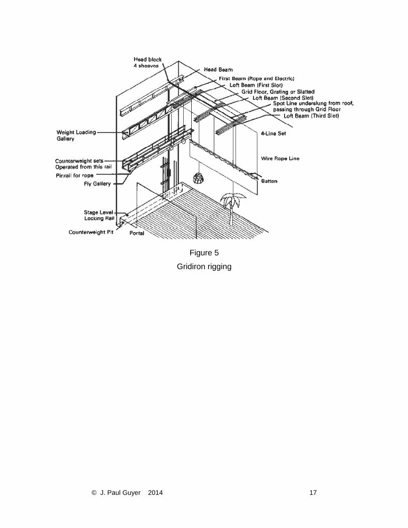
Figure 5
Gridiron rigging

© J. Paul Guyer 2014 18
4. RIGGING AND STAGE MECHANISMS
4.1 COMMENTARY. Selection of systems is based on anticipated performance uses.
4.1.1 FLY-LOFT COMPONENTS. Scenery, drapes and lights are moved vertically by a
system of lines, pulleys, counterweights and/or winches supporting a pipe, all of which
constitute a set. Sets are supported on a structural grating, the gridiron, above the stage
and fixed in place at a pinrail or locking rail anchored to the stagehouse wall, floor, or fly
gallery. Gridiron is positioned to allow man-high working space below the roof structure.
Loft beams comprised of 10 inch steel channels extend the full depth of the stagehouse
in pairs, providing a cable slot every 10 or 12 feet. The grid floor normally consists of
1½" x 3" channel steel laid webup 6" on center, or 1½" subway grating. Individual lines
can thus be dropped through almost anywhere on stage. At one end of the stagehouse,
major head block beams resist the lateral and vertical loads imposed by the sets. Line
sets consist of two or more rope or wire cable lines attached to each flown unit as it
rests on the stage floor. The lines run up over moveable loft blocks mounted on the loft
beams; blocks shift up and downstage for adjustment. Individual (single) rope lines may
also pass through the grid floor. The lines of each set are
Table 2
Typical line sets needed
collected at a head block with multiple sheaves and then pass downward. Each set is
trimmed to equalize tension according to the load, and hoisted as a unit. Battens are
loaded with a gross weight of 30 pounds per linear foot and usually extend 3 to 5 feet

© J. Paul Guyer 2014 19
past the proscenium opening. Rope lines are tied off on a pinrail, which is the onstage
edge of the fly gallery from which the flies are operated. Each line may be sandbagged
to adjust tension. The fly gallery keeps this activity away from the stage floor, where
space is highly-valued. The gallery’s elevation is usually set by the tallest piece of
standing scenery and the ability to see into the flies-that is, 20 to 30 feet above the floor,
and at least as high as the proscenium opening. Wire line sets are counterweight sets.
After passing over the head block, the lines are fastened by chains and turnbuckles to a
counterweight carriage. The turnbuckles enable the set to be trimmed. The carriage
runs up and down, usually at the wall, travelling a distance equal to that travelled by the
flown pipe. The weights are pig-iron, added incrementally until the set is
counterbalanced to a degree that permits manual operation by pulling on a manila
purchase line attached to the top of the carriage, running over the headblock, down

© J. Paul Guyer 2014 20
Figure 5
Traps
through a rope lock to a tension block at the floor and up again to the carriage. The lines
are operated from the fly gallery or from stage floor, but the weights are stored and
added at a loading gallery at the top of the carriage run, level with the carriage bottom to
minimize lifting. Dimensional difficulties in the design of counterweight systems usually
require provision of a counterweight pit in the stage floor to increase carriage travel. If it
is absolutely essential that the floor be kept clear (e.g., for the movement of scene
wagons) a combination of pulleys can reduce carriage travel to half the fly, by placing
the tension block at fly gallery elevation- a complicated, expensive, and inconvenient
arrangement. There are three kinds of carriage guide systems. The least costly is the
wire guide, two tensioned cables engaged by the carriage. Since there are no wall
anchors, the sets can be moved up and downstage. Carriage sway requires they be
spaced approximately a foot apart to avoid fouling. The maximum height of wire guide
systems is 30 feet. T-Track guides are steel or aluminum rails standing out from the

© J. Paul Guyer 2014 21
wall, each engaged by two carriages. The resultant close grouping of sets provides the
maximum number of available sets per linear depth of stage, but where only a few sets
are installed in a group, their effective gridiron coverage is limited by the divergent angle
of lines passing over the head blocks. Lattice tracks for single carriages consist of two
guide rails separated by ladder-like rungs. They are useful for isolated sets such as
house curtains or fire curtains. Winch systems are based on a somewhat different
organizational logic. The gridiron line set concept assumes that most flown material is
arranged in parallel planes behind the proscenium. However, there are situations in
which randomly located lines are of great value; for instance, for diagonal drops and
flown orchestra shells and reflectors. The winch lines can be used in combination with
conventional sets by locating the loft blocks above the gridiron, underslung from the roof
structure. Each line is taken up on a rotating drum driven by a speed-controlled
synchronous motor. Controls can be located anywhere and there are no weight guides,
lines, sandbags or pinrails to deal with. However, winches are expensive and slow-
acting. A similar single-line arrangement with overhead blocks can be used to hang
lightweight objects above an open stage, the lines tied back to catwalk rails.
Counterweight sets can also be winch driven, which is considered safer because the
winch takes up only part of the load.
4.1.2 STAGE-LEVEL COMPONENTS. Standing scenery is moved horizontally on
casters and dollies, or on tracked chassis called wagons, or on turntables. The decision
to employ roll-on scene pieces must be part of early planning, since it has great impact
on the organization of other stagehouse mechanisms. Wagon guide tracks, if used,
must be recessed in the floor. This will affect structure, trap locations, details of
wingspace layout, and the form of cyclorama and other accessories such as lightbooms
that might otherwise be floor-supported. Steel plate tracks are needed to prevent
damage to the softwood floor. Rolling sets have beneficial application to the open stage
without flyloft, and to musical drama employing elaborate constructed scenery as well
as flown pieces. Wagons are also commonly built by the user as part of portable
scenery. Wing space is used to hold these wagons when they are not on stage. Each
scene change involves clearing the stage floor and moving the next set in. Each wagon

© J. Paul Guyer 2014 22
Figure 6
Pit infill method
Figure 7
Orchestra pit plan
must also have a storage area out of the scene space. Wing storage can be used in
several ways. Wagons slightly wider than the acting area can be moved laterally in one
motion from either wing; the total stagehouse dimension will be at least four times the
proscenium width. Wagons half as wide can be brought together at center for one
scene. A second pair upstage forms the next scene, if the stagehouse depth is
sufficient. Wagons can jackknife at a downstage pivot point, reducing the wing
dimension required, but sweeping a large area. Wing storage takes up a great deal of
space, congesting side entries. If more than two scenes are required, free storage must
be associated with each wagon, so that one may be changed while the other is in use.
In that case, any wing storage scheme involves an exceptionally broad stagehouse.

© J. Paul Guyer 2014 23
Upstage storage can be used to serve additional wagons or to minimize wingspace use.
It has the advantage of avoiding pinrail and line sets for the flyloft, and need be only as
high as the tallest piece of scenery. A deep stagehouse has other benefits in terms of
multi-use and rear projection capability.
Offstage storage may be regarded as the logical conclusion. If wagons can be moved
out of the stagehouse, scene changes can be effected without noise in the performance
Room and under superior conditions of work-lighting and mechanical aids. At other
times, the wagon room can be used for set construction and rehearsals. Turntables,
while mechanically complex and somewhat more costly, avoid the problem of
wingspace interference. Three or four scenes can be constructed on a large revolve and
moved into place in no time. Even more scenes can be managed by resetting the
segments facing the wingspace. The disadvantages of turntables include the geometric
constraints imposed on the scene designer and the restriction of backgrounds to drops
that cannot hang to the floor. If the table is demountable, the stage floor must be built up
around it, altering sightline conditions. All permanent mechanisms such as wagons and
turntables are useful only to the resident user. Touring companies do not expect to find
these devices and plan their shows without them.
4.1.3 UNDERSTAGE COMPONENTS. Scenery and actors are moved vertically from
below stage through a system of removable traps, on lifts, hoists or stairs and ladders.
Included in this concept are orchestra pit elevators and forestage lifts.
Traps are removable sections of the stage floor by which actors can enter or descend
from the acting area, scenery pushed or hoisted up, or special lighting effects obtained.
In comparison to other stage mechanisms, traps are among the best dollar-value assets
for the drama stage. Traps are most often used in open stage, projected and surround
Rooms as an alternative to the run-on entry from the house, and sometimes are the
only way to dispose of scene properties that can’t be hoisted into a loft.

© J. Paul Guyer 2014 24
Figure 8
Orchestra pit setups
Stage elevators used by major opera companies enable whole scene wagons to be
brought from below, a luxury too exotic for consideration at the scale of many MDC’s.
Large stages for music performance in particular may merit installation of low-speed
geared or screwjack carriages designed to raise a portion of the stage rather than
building up on it. An apron platform and/or hydraulic pit lift is also desirable but of
questionable priority in relation to regular use. The pit lift is probably more important
than the stage lift. Only exceptional programming and high labor costs can justify the
expense. The feasibility of limited travel platform lifts used in combination with a pit
cover and infill units should be examined if a mixed program of full orchestra, orchestra
and chorus, musical drama and/or dance is contemplated. Unfortunately, there is a
tendency to leave things in place if they can’t be altered easily. Correct sightlines must
be planned for the full extension of the stage. The stage apron is in need of the same
services as the rear portion of the stage, and should be provided with the same density
of rigging, sets, electric pipes, and circuits.
4.1.4 ORCHESTRA PIT. This is indeed a valuable facility where any combination of
music and speech is contemplated. In addition to the sightline considerations affecting
© J. Paul Guyer 2014 25
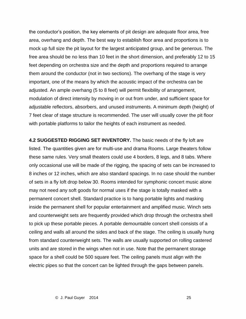
the conductor’s position, the key elements of pit design are adequate floor area, free
area, overhang and depth. The best way to establish floor area and proportions is to
mock up full size the pit layout for the largest anticipated group, and be generous. The
free area should be no less than 10 feet in the short dimension, and preferably 12 to 15
feet depending on orchestra size and the depth and proportions required to arrange
them around the conductor (not in two sections). The overhang of the stage is very
important, one of the means by which the acoustic impact of the orchestra can be
adjusted. An ample overhang (5 to 8 feet) will permit flexibility of arrangement,
modulation of direct intensity by moving in or out from under, and sufficient space for
adjustable reflectors, absorbers, and unused instruments. A minimum depth (height) of
7 feet clear of stage structure is recommended. The user will usually cover the pit floor
with portable platforms to tailor the heights of each instrument as needed.
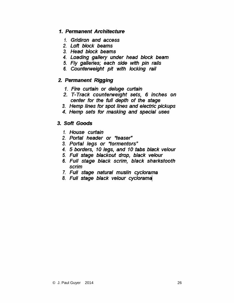
4.2 SUGGESTED RIGGING SET INVENTORY. The basic needs of the fly loft are
listed. The quantities given are for multi-use and drama Rooms. Large theaters follow
these same rules. Very small theaters could use 4 borders, 8 legs, and 8 tabs. Where
only occasional use will be made of the rigging, the spacing of sets can be increased to
8 inches or 12 inches, which are also standard spacings. In no case should the number
of sets in a fly loft drop below 30. Rooms intended for symphonic concert music alone
may not need any soft goods for normal uses if the stage is totally masked with a
permanent concert shell. Standard practice is to hang portable lights and masking
inside the permanent shell for popular entertainment and amplified music. Winch sets
and counterweight sets are frequently provided which drop through the orchestra shell
to pick up these portable pieces. A portable demountable concert shell consists of a
ceiling and walls all around the sides and back of the stage. The ceiling is usually hung
from standard counterweight sets. The walls are usually supported on rolling castered
units and are stored in the wings when not in use. Note that the permanent storage
space for a shell could be 500 square feet. The ceiling panels must align with the
electric pipes so that the concert can be lighted through the gaps between panels.
© J. Paul Guyer 2014 26


![Architectural categories and acoustic characteristics of ... · Chinese architectural history [2]. Architectural categories and characteristics of tra-ditional Chinese theatres .](https://static.fdocuments.in/doc/165x107/6007784cbb3ce4085c1b120d/architectural-categories-and-acoustic-characteristics-of-chinese-architectural.jpg)