An Interactive Web-Based Ray Tracing Visualization Tool
23
An Interactive Web-Based Ray Tracing Visualization Tool by Jake A. Russell submitted June 10, 1999 to the Department of Computer Science, University of Washington as Undergraduate Honors Program Senior Thesis Requirement Copyright 1999 Jake A. Russell. All rights reserved. Faculty Supervisor signature: Date: Brian Curless Undergraduate Faculty Advisor signature: Date: Gaetano Borriello
Transcript of An Interactive Web-Based Ray Tracing Visualization Tool
An Interactive Web-Based Ray Tracing Visualization Tool
by
Jake A. Russell
submitted June 10, 1999
to the
Department of Computer Science, University of Washington
as
Undergraduate Honors Program Senior Thesis Requirement
Copyright 1999 Jake A. Russell. All rights reserved.
Faculty Supervisor signature:
Date: Brian Curless
Undergraduate Faculty Advisor signature:
Date: Gaetano Borriello
2
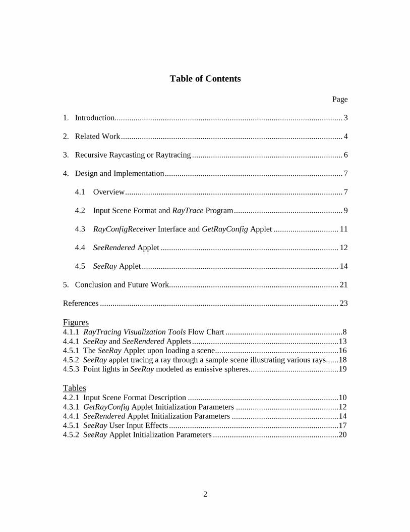
Table of Contents
Page
1. Introduction............................................................................................................. 3
2. Related Work.......................................................................................................... 4
3. Recursive Raycasting or Raytracing ........................................................................ 6
4. Design and Implementation..................................................................................... 7
4.1 Overview........................................................................................................ 7
4.2 Input Scene Format and RayTrace Program.................................................... 9
4.3 RayConfigReceiver Interface and GetRayConfig Applet ............................... 11
4.4 SeeRendered Applet ..................................................................................... 12
4.5 SeeRay Applet .............................................................................................. 14
5. Conclusion and Future Work................................................................................. 21
References .................................................................................................................. 23
Figures4.1.1 RayTracing Visualization Tools Flow Chart ........................................................84.4.1 SeeRay and SeeRendered Applets......................................................................134.5.1 The SeeRay Applet upon loading a scene...........................................................164.5.2 SeeRay applet tracing a ray through a sample scene illustrating various rays......184.5.3 Point lights in SeeRay modeled as emissive spheres...........................................19
Tables4.2.1 Input Scene Format Description ........................................................................104.3.1 GetRayConfig Applet Initialization Parameters .................................................124.4.1 SeeRendered Applet Initialization Parameters ...................................................144.5.1 SeeRay User Input Effects .................................................................................174.5.2 SeeRay Applet Initialization Parameters ............................................................20
3
1. Introduction
Ray tracing is a simple yet powerful rendering technique for creating realistic
images of complex scenes. Due to the simplicity and popularity of the technique, it is
typically part of collegiate-level computer graphics course curricula.
However, education of a technique as three-dimensionally oriented as ray
tracing is impeded by the typical two-dimensional medium of communication used in
the classroom because the surface of a whiteboard or overhead projector in many
instances cannot do justice in fully illustrating a three-dimensional concept. Raycasting
and ray tracing are particularly suited to a three-dimensional visualization due to the
important relationship of rays with scene object geometry.
The solution was to create a computer visualization that in real time can provide
various views of the rays and the scene objects projected onto a computer screen.
Because the number of courses incorporating multimedia devices in the classroom are
increasing and courses are generally shifting more to a web-based or web-supported
format, designing the computer visualization as a set of Applets is potentially the best
medium for interactive educational aids. Java Applets allow educators as much
flexibility as possible in easily incorporating the educational aids into their courses.
4
All Applets described in this paper are available for free and public download
from the Ray Tracing Visualization Tools Website.1
Two direct beneficiaries of this project will be the University of Washington
introductory and advanced courses in computer graphics, CSE457 and CSE557,
respectively.
2. Related Work
Raytracing visualization programs have been created in the past for SGI
machines, such as Ben Garlick’s Flyray [GARLICK89]. Flyray traces an input scene in
real time and as the rays are being shot through the scene, the scene and rays appear in
the scene visualization to be viewed from a navigable viewpoint. This is a very useful
visualization. However, we make two important improvements on it.
First, our ray tracing visualization engine is able to function with pre-rendered
scene image files. We provide the tool that reads the input file and outputs the
raytraced scene either on-screen as an Applet window or to be saved on-file as an
executable Java Class. By running the ray tracing tool as an Applet in an HTML page,
the image will render on-the-fly onto the web page containing the scene visualization,
giving the same functionality as Flyray. But by running the ray tracing tool as a Java
1 http://www.cs.washington.edu/research/graphics/software-data/seeray
5
Program, various rendered image files can be generated and saved, to be recalled by the
Applet or HTML page instantaneously as needed. We provide an Applet that will load
various rendered images of different ray tracing engine parameters during run time
provided there is a library of pre-rendered images made available. The benefit is that
subtle differences in ray tracing engine parameters can have their rendered images
compared back-to-back with the ray tracing visualization engine, possibly active in the
same HTML page, with rendering engine parameters updated accordingly.
The second tangible improvement our ray tracing visualization engine employs
is the advantage of a platform-independent running environment. Recently, there has
been an explosion in the number of Java Applet-based educational aids such as those
used in the Massachusetts Institute of Technology’s curriculum for Computer Graphics
Course 6.831 [TELLER98]. Other numerous examples can be found in Brown
University Computer Graphics Group’s Exploratory educational applet archival
website.2 Beall, Doppelt, and Hughes describe the development of one example in their
work [BEALL96]. By designing our tools as Java Applets, we ensure that a broad
variety of platforms and operating systems will be able to run them.
It should also be noted that our Java ray tracing engine is derived from Leonard
McMillan’s RayTrace skeleton code [MCMILLAN98].
2 http://www.cs.brown.edu/exploratory
6
3. Recursive Raycasting or Raytracing
The ray tracing engine used in our visualization tools can be set to demonstrate
the nonrecursive raycasting algorithm [APPEL68] or the more involved recursive
algorithm of ray tracing where reflection and refraction are modeled [WHITTED80]. In
either case it simulates shadows and uses a shading model incorporating surface
shininess developed by Bui-Thoung Phong [PHONG75].
The ray tracing engine incorporates shadow detection through the use of shadow
rays, originally discussed in one of the first papers written on ray tracing [APPEL68].
For each light source a shadow ray is fired from each point of intersection to the light
position and, if any scene object geometry intersects the shadow ray, then light from
that source will be partially or completely occluded.
The engine also employs the recursive ray-spawning techniques developed by
Turner Whitted [WHITTED80] resulting in the generation of reflected rays and
refracted rays as required, depending on how surface material properties at the point of
intersection are defined. The ray emanating from the center of projection is thus called
the primary ray, while recursively spawned rays are secondary rays. Reflective,
mirror-like surfaces can be modeled as well as transparent surfaces for any arbitrary
index of refraction.
7
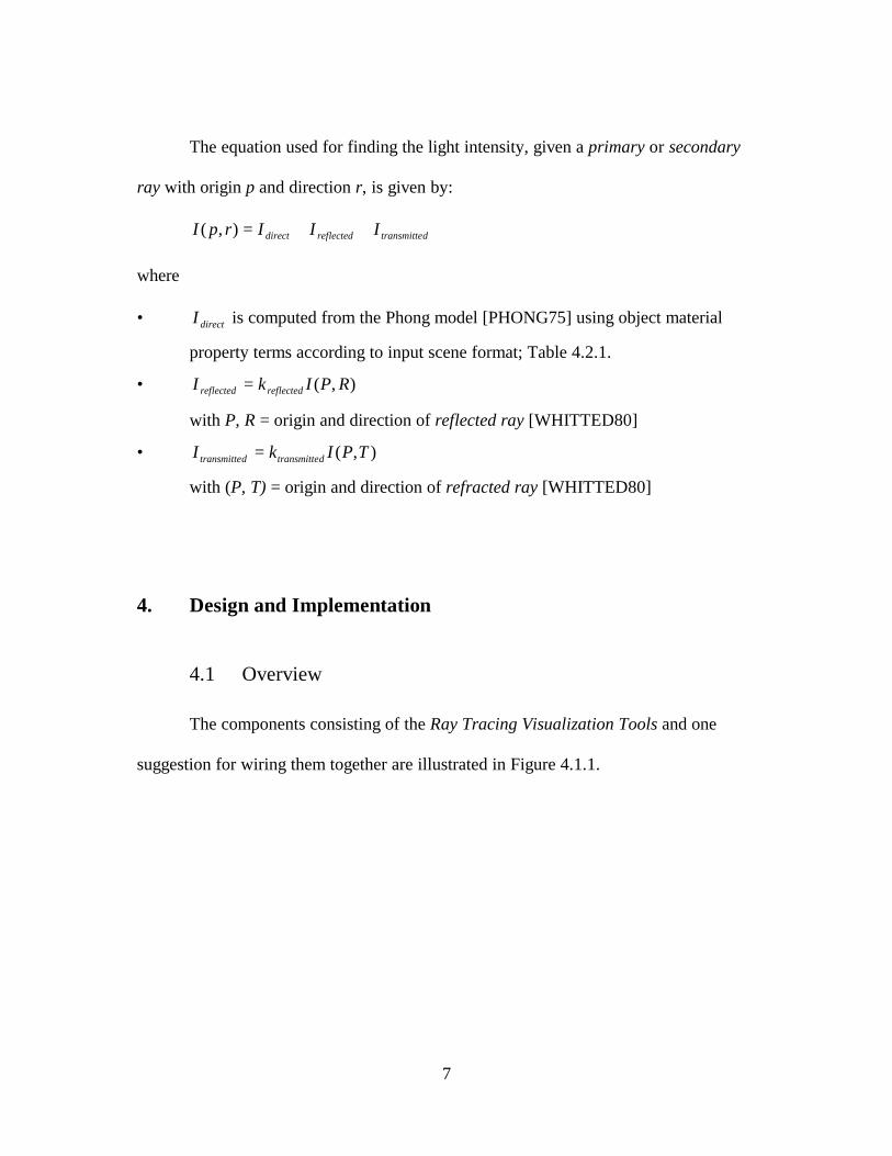
The equation used for finding the light intensity, given a primary or secondary
ray with origin p and direction r, is given by:
dtransmittereflecteddirect IIIrpI ++=),(
where
• directI is computed from the Phong model [PHONG75] using object material
property terms according to input scene format; Table 4.2.1.
• ),( RPIkI reflectedreflected =
with P, R = origin and direction of reflected ray [WHITTED80]
• ),( TPIkI dtransmittedtransmitte =
with (P, T) = origin and direction of refracted ray [WHITTED80]
4. Design and Implementation
4.1 Overview
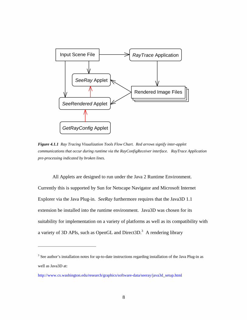
The components consisting of the Ray Tracing Visualization Tools and one
suggestion for wiring them together are illustrated in Figure 4.1.1.
8
Figure 4.1.1 Ray Tracing Visualization Tools Flow Chart. Red arrows signify inter-applet
communications that occur during runtime via the RayConfigReceiver interface. RayTrace Application
pre-processing indicated by broken lines.
All Applets are designed to run under the Java 2 Runtime Environment.
Currently this is supported by Sun for Netscape Navigator and Microsoft Internet
Explorer via the Java Plug-in. SeeRay furthermore requires that the Java3D 1.1
extension be installed into the runtime environment. Java3D was chosen for its
suitability for implementation on a variety of platforms as well as its compatibility with
a variety of 3D APIs, such as OpenGL and Direct3D.3 A rendering library
3 See author’s installation notes for up-to-date instructions regarding installation of the Java Plug-in as
well as Java3D at:
http://www.cs.washington.edu/research/graphics/software-data/seeray/java3d_setup.html
Input Scene File
Rendered Image Files
RayTrace Application
SeeRay Applet
SeeRendered Applet
GetRayConfig Applet
9
implementing 3D hardware acceleration should be used whenever possible to maximize
scene rendering performance. Java 2 and Java3D are currently supported on the
Windows and Solaris platforms, with a future version for the SGI IRIX platform to
most likely be released in the near future.
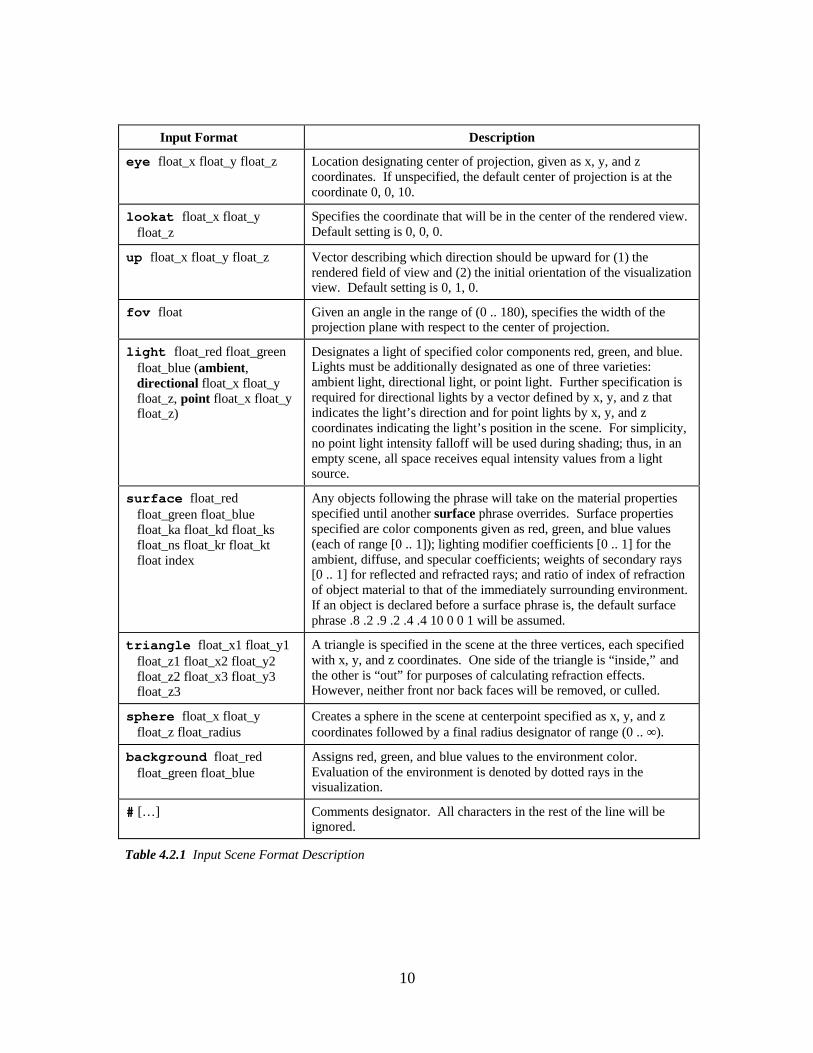
4.2 Input Scene Format and RayTrace Program
The input scene is a text file specified to the Applets via relative URL. The
scene file is parsed as a sequence of phrases specified in Table 4.2.1.
The name of the scene file is additionally used by SeeRay and SeeRendered in
the referencing of any pre-rendered image files. The name format for pre-rendered
image files is [sceneinputname].[minweight].[maxdepth].jpeg
Generation of pre-rendered images can be done using the supplied RayTrace
utility, when run as a Java Program. The RayTrace utility is derived from Leonard
McMillan’s RayTrace skeleton code [MCMILLAN98]. It takes minweight, maxdepth,
and datafile input parameters and renders an appropriate ray traced image to a window.
Clicking the mouse in the window after the scene is rendered results in the rendered
image to be saved as an uncompressed, appropriately named JPEG. Although RayTrace
may be run as an Applet, it would then not be able to save output image files due to
Java Applet security restrictions.
10
Input Format Description
eye float_x float_y float_z Location designating center of projection, given as x, y, and zcoordinates. If unspecified, the default center of projection is at thecoordinate 0, 0, 10.
lookat float_x float_yfloat_z
Specifies the coordinate that will be in the center of the rendered view.Default setting is 0, 0, 0.
up float_x float_y float_z Vector describing which direction should be upward for (1) therendered field of view and (2) the initial orientation of the visualizationview. Default setting is 0, 1, 0.
fov float Given an angle in the range of (0 .. 180), specifies the width of theprojection plane with respect to the center of projection.
light float_red float_greenfloat_blue (ambient,directional float_x float_yfloat_z, point float_x float_yfloat_z)
Designates a light of specified color components red, green, and blue.Lights must be additionally designated as one of three varieties:ambient light, directional light, or point light. Further specification isrequired for directional lights by a vector defined by x, y, and z thatindicates the light’s direction and for point lights by x, y, and zcoordinates indicating the light’s position in the scene. For simplicity,no point light intensity falloff will be used during shading; thus, in anempty scene, all space receives equal intensity values from a lightsource.
surface float_redfloat_green float_bluefloat_ka float_kd float_ksfloat_ns float_kr float_ktfloat index
Any objects following the phrase will take on the material propertiesspecified until another surface phrase overrides. Surface propertiesspecified are color components given as red, green, and blue values(each of range [0 .. 1]); lighting modifier coefficients [0 .. 1] for theambient, diffuse, and specular coefficients; weights of secondary rays[0 .. 1] for reflected and refracted rays; and ratio of index of refractionof object material to that of the immediately surrounding environment.If an object is declared before a surface phrase is, the default surfacephrase .8 .2 .9 .2 .4 .4 10 0 0 1 will be assumed.
triangle float_x1 float_y1float_z1 float_x2 float_y2float_z2 float_x3 float_y3float_z3
A triangle is specified in the scene at the three vertices, each specifiedwith x, y, and z coordinates. One side of the triangle is “inside,” andthe other is “out” for purposes of calculating refraction effects.However, neither front nor back faces will be removed, or culled.
sphere float_x float_yfloat_z float_radius
Creates a sphere in the scene at centerpoint specified as x, y, and zcoordinates followed by a final radius designator of range (0 .. ∞ ).
background float_redfloat_green float_blue
Assigns red, green, and blue values to the environment color.Evaluation of the environment is denoted by dotted rays in thevisualization.
# [… ] Comments designator. All characters in the rest of the line will beignored.
Table 4.2.1 Input Scene Format Description
11
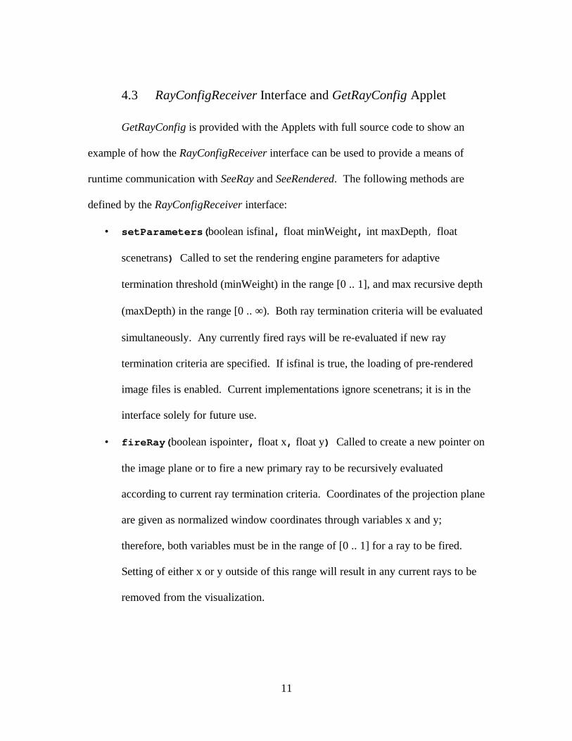
4.3 RayConfigReceiver Interface and GetRayConfig Applet
GetRayConfig is provided with the Applets with full source code to show an
example of how the RayConfigReceiver interface can be used to provide a means of
runtime communication with SeeRay and SeeRendered. The following methods are
defined by the RayConfigReceiver interface:
• setParameters(boolean isfinal, float minWeight, int maxDepth, float
scenetrans) Called to set the rendering engine parameters for adaptive
termination threshold (minWeight) in the range [0 .. 1], and max recursive depth
(maxDepth) in the range [0 .. ∞). Both ray termination criteria will be evaluated
simultaneously. Any currently fired rays will be re-evaluated if new ray
termination criteria are specified. If isfinal is true, the loading of pre-rendered
image files is enabled. Current implementations ignore scenetrans; it is in the
interface solely for future use.
• fireRay(boolean ispointer, float x, float y) Called to create a new pointer on
the image plane or to fire a new primary ray to be recursively evaluated
according to current ray termination criteria. Coordinates of the projection plane
are given as normalized window coordinates through variables x and y;
therefore, both variables must be in the range of [0 .. 1] for a ray to be fired.
Setting of either x or y outside of this range will result in any current rays to be
removed from the visualization.
12
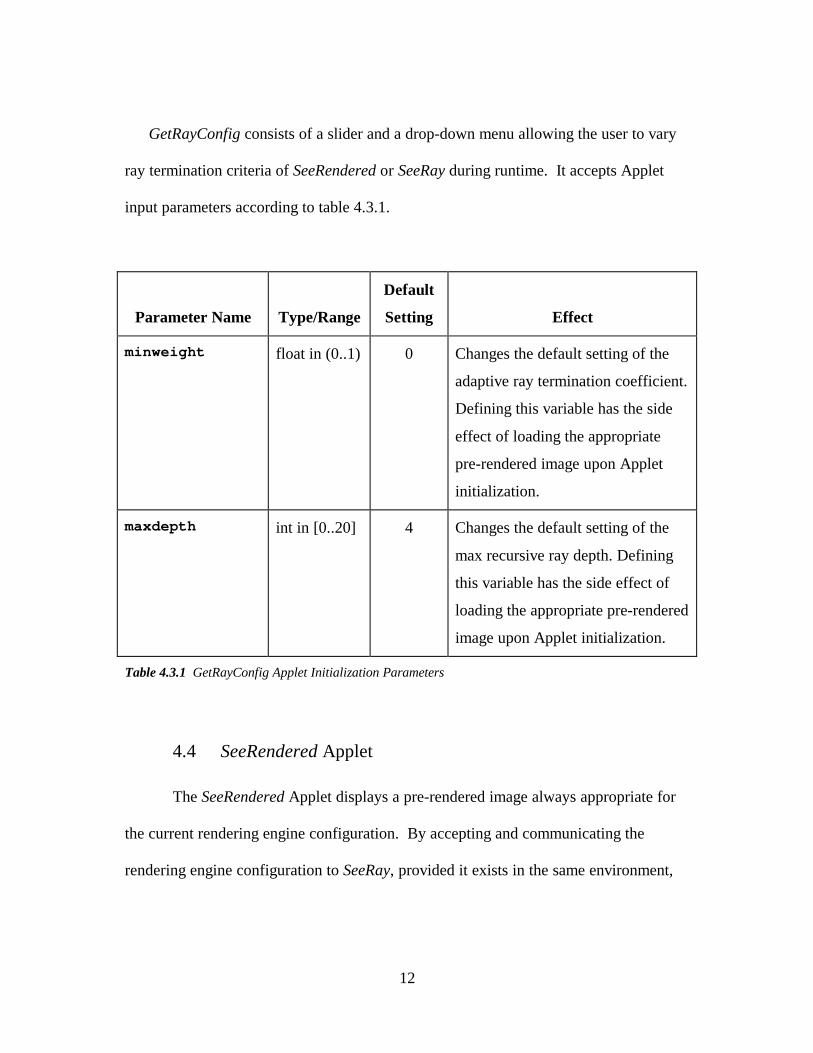
GetRayConfig consists of a slider and a drop-down menu allowing the user to vary
ray termination criteria of SeeRendered or SeeRay during runtime. It accepts Applet
input parameters according to table 4.3.1.
Parameter Name Type/Range
Default
Setting Effect
minweight float in (0..1) 0 Changes the default setting of the
adaptive ray termination coefficient.
Defining this variable has the side
effect of loading the appropriate
pre-rendered image upon Applet
initialization.
maxdepth int in [0..20] 4 Changes the default setting of the
max recursive ray depth. Defining
this variable has the side effect of
loading the appropriate pre-rendered
image upon Applet initialization.
Table 4.3.1 GetRayConfig Applet Initialization Parameters
4.4 SeeRendered Applet
The SeeRendered Applet displays a pre-rendered image always appropriate for
the current rendering engine configuration. By accepting and communicating the
rendering engine configuration to SeeRay, provided it exists in the same environment,
13
communications will automatically propagate, i.e., both Applets will remain in sync
with a single communication to SeeRendered.
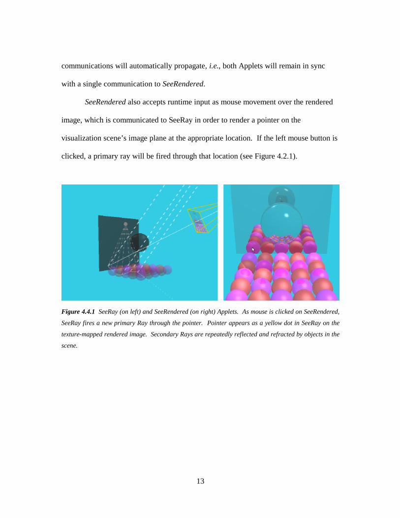
SeeRendered also accepts runtime input as mouse movement over the rendered
image, which is communicated to SeeRay in order to render a pointer on the
visualization scene’s image plane at the appropriate location. If the left mouse button is
clicked, a primary ray will be fired through that location (see Figure 4.2.1).
Figure 4.4.1 SeeRay (on left) and SeeRendered (on right) Applets. As mouse is clicked on SeeRendered,
SeeRay fires a new primary Ray through the pointer. Pointer appears as a yellow dot in SeeRay on the
texture-mapped rendered image. Secondary Rays are repeatedly reflected and refracted by objects in the
scene.
14
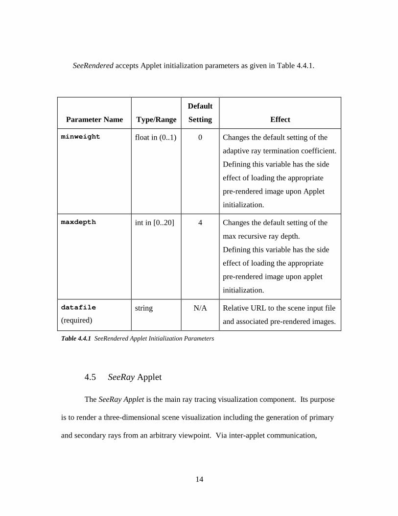
SeeRendered accepts Applet initialization parameters as given in Table 4.4.1.
Parameter Name Type/Range
Default
Setting Effect
minweight float in (0..1) 0 Changes the default setting of the
adaptive ray termination coefficient.
Defining this variable has the side
effect of loading the appropriate
pre-rendered image upon Applet
initialization.
maxdepth int in [0..20] 4 Changes the default setting of the
max recursive ray depth.
Defining this variable has the side
effect of loading the appropriate
pre-rendered image upon applet
initialization.
datafile
(required)string N/A Relative URL to the scene input file
and associated pre-rendered images.
Table 4.4.1 SeeRendered Applet Initialization Parameters
4.5 SeeRay Applet
The SeeRay Applet is the main ray tracing visualization component. Its purpose
is to render a three-dimensional scene visualization including the generation of primary
and secondary rays from an arbitrary viewpoint. Via inter-applet communication,

15
SeeRay accepts commands during runtime to (a) vary the ray tracing engine’s ray
termination settings, and (b) indicate where a new pointer should be positioned or a new
primary ray should be fired. These commands are issued to SeeRay in accordance with
the RayConfigReceiver interface, described in detail in Section 4.3.
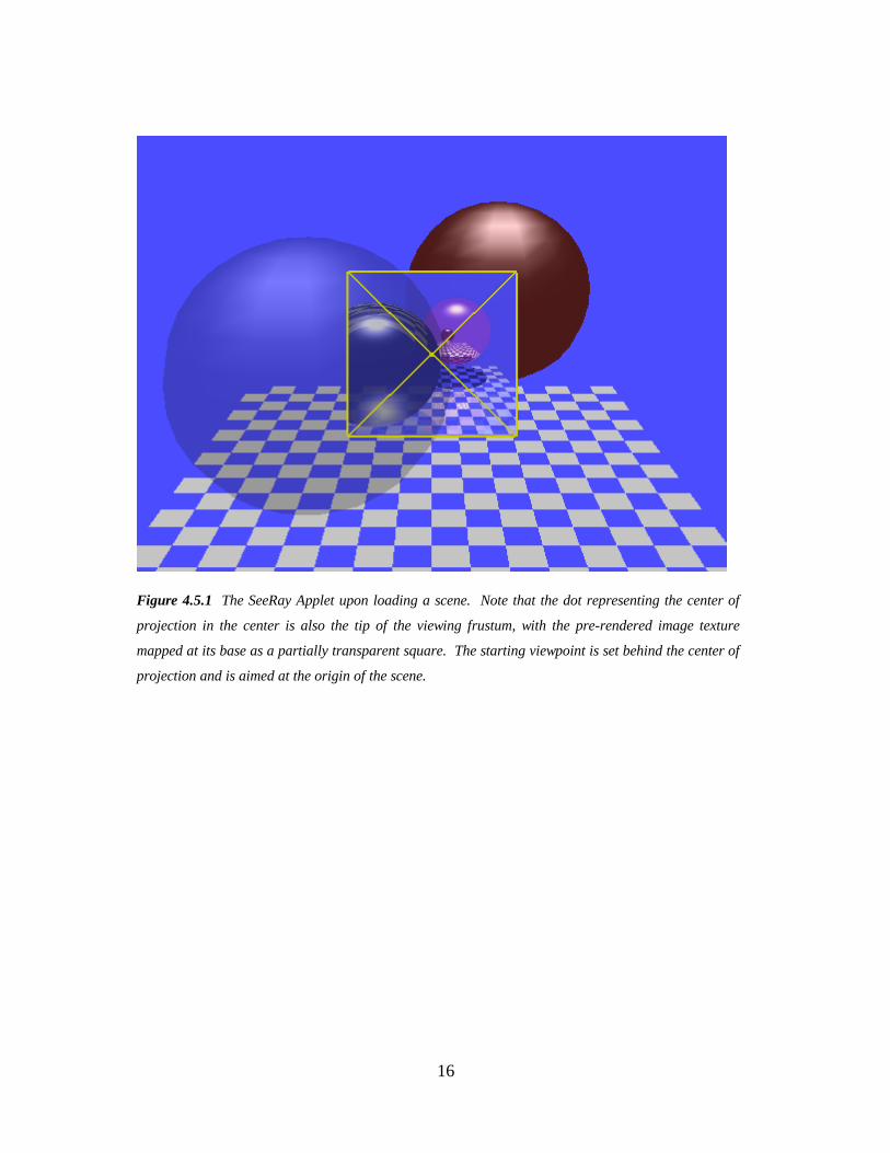
Upon applet startup, the visualization viewpoint is set at a location behind the
scene’s center of projection and pointing in a direction toward the origin, as in
Figure 4.5.1. The roll angle of the visualization viewpoint is set by default in
accordance with the up vector defined in the scene input file.
16
Figure 4.5.1 The SeeRay Applet upon loading a scene. Note that the dot representing the center of
projection in the center is also the tip of the viewing frustum, with the pre-rendered image texture
mapped at its base as a partially transparent square. The starting viewpoint is set behind the center of
projection and is aimed at the origin of the scene.
17
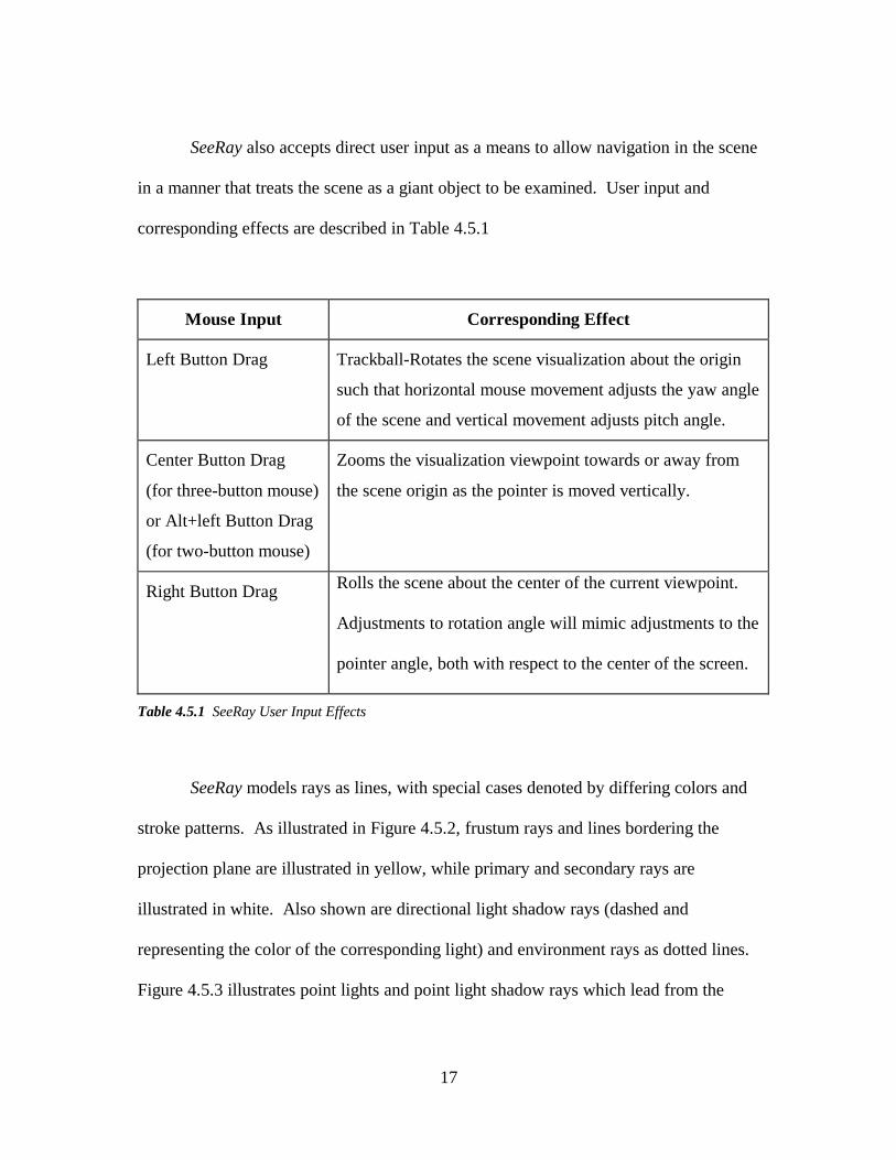
SeeRay also accepts direct user input as a means to allow navigation in the scene
in a manner that treats the scene as a giant object to be examined. User input and
corresponding effects are described in Table 4.5.1
Mouse Input Corresponding Effect
Left Button Drag Trackball-Rotates the scene visualization about the origin
such that horizontal mouse movement adjusts the yaw angle
of the scene and vertical movement adjusts pitch angle.
Center Button Drag
(for three-button mouse)
or Alt+left Button Drag
(for two-button mouse)
Zooms the visualization viewpoint towards or away from
the scene origin as the pointer is moved vertically.
Right Button Drag Rolls the scene about the center of the current viewpoint.
Adjustments to rotation angle will mimic adjustments to the
pointer angle, both with respect to the center of the screen.
Table 4.5.1 SeeRay User Input Effects
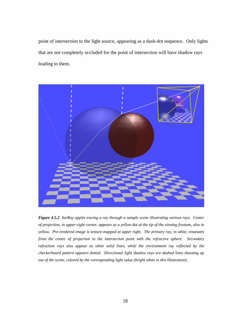
SeeRay models rays as lines, with special cases denoted by differing colors and
stroke patterns. As illustrated in Figure 4.5.2, frustum rays and lines bordering the
projection plane are illustrated in yellow, while primary and secondary rays are
illustrated in white. Also shown are directional light shadow rays (dashed and
representing the color of the corresponding light) and environment rays as dotted lines.
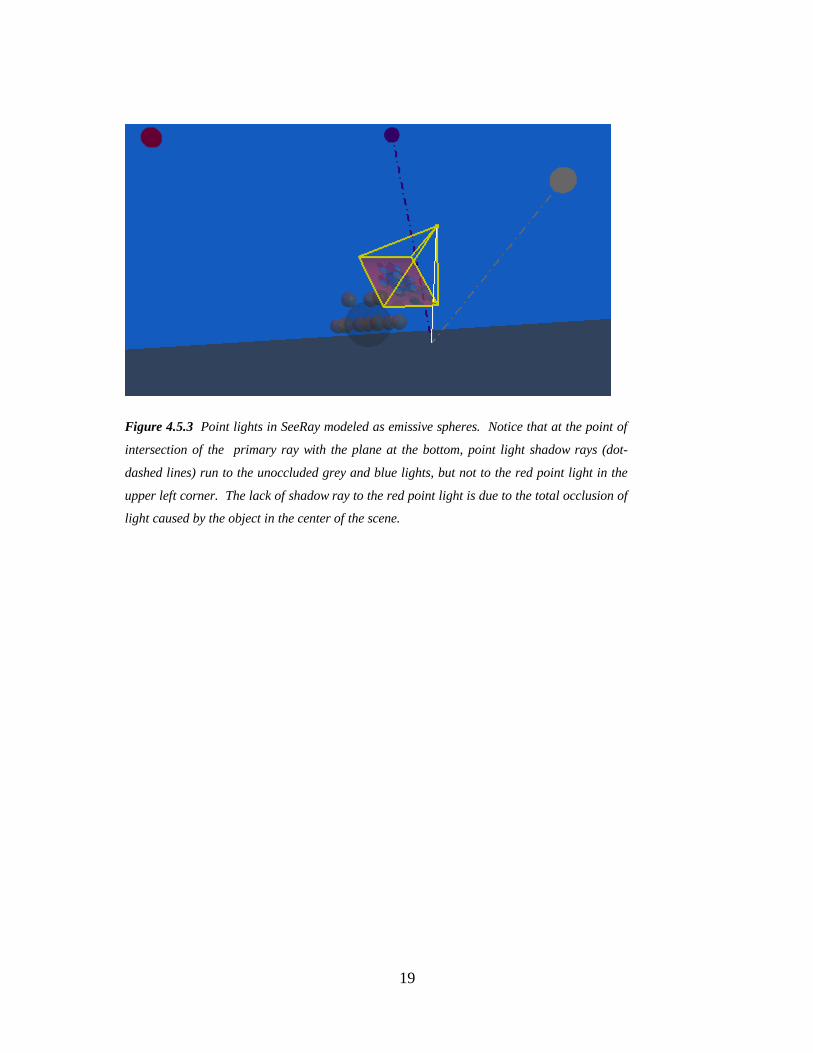
Figure 4.5.3 illustrates point lights and point light shadow rays which lead from the
18
point of intersection to the light source, appearing as a dash-dot sequence. Only lights
that are not completely occluded for the point of intersection will have shadow rays
leading to them.
Figure 4.5.2 SeeRay applet tracing a ray through a sample scene illustrating various rays. Center
of projection, in upper-right corner, appears as a yellow dot at the tip of the viewing frustum, also in
yellow. Pre-rendered image is texture-mapped at upper right. The primary ray, in white, emanates
from the center of projection to the intersection point with the refractive sphere. Secondary
refraction rays also appear as white solid lines, while the environment ray reflected by the
checkerboard pattern appears dotted. Directional light shadow rays are dashed lines shooting up
out of the scene, colored by the corresponding light value (bright white in this illustration).
19
Figure 4.5.3 Point lights in SeeRay modeled as emissive spheres. Notice that at the point of
intersection of the primary ray with the plane at the bottom, point light shadow rays (dot-
dashed lines) run to the unoccluded grey and blue lights, but not to the red point light in the
upper left corner. The lack of shadow ray to the red point light is due to the total occlusion of
light caused by the object in the center of the scene.
20
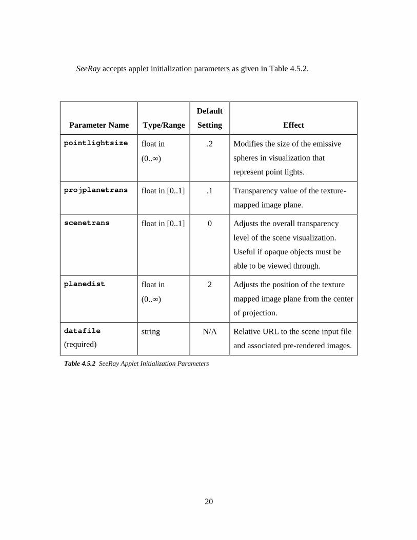
SeeRay accepts applet initialization parameters as given in Table 4.5.2.
Parameter Name Type/Range
Default
Setting Effect
pointlightsize float in
(0..∞ )
.2 Modifies the size of the emissive
spheres in visualization that
represent point lights.
projplanetrans float in [0..1] .1 Transparency value of the texture-
mapped image plane.
scenetrans float in [0..1] 0 Adjusts the overall transparency
level of the scene visualization.
Useful if opaque objects must be
able to be viewed through.
planedist float in
(0..∞ )
2 Adjusts the position of the texture
mapped image plane from the center
of projection.
datafile
(required)string N/A Relative URL to the scene input file
and associated pre-rendered images.
Table 4.5.2 SeeRay Applet Initialization Parameters
21
5. Conclusion and Future Work
The possibilities of future interactive educational aid development to enhance
the education of computer graphics concepts are exciting. Although our ray tracing
visualization software is a nice start, there are a few specific modifications worth
mentioning that could prove worthwhile.
One extension would be to modify SeeRay so it can send inter-applet
communications. Additional Applets could then be created to offer information during
runtime about which objects in the scene are currently under the mouse in SeeRay, or
the Applets might organize the rays currently displayed by SeeRay into a tree-view
format. It would then be possible to analyze an individual point of intersection or ray
appearing in the visualization with an additional query to the Applet.
We would also like to extend the functionality offered by SeeRay itself. SeeRay
currently offers no visualization of spatial optimization techniques, a potentially useful
feature. It would be a welcome extension to the Applet for a three dimensional
representation of bounding spheres, axis-aligned bounding boxes, and K-D trees to be
implemented. Volumes or regions in space where intersection points lie, or through
which rays pierce, might be denoted in the visualization through colored transparent
objects. Potentially, performance data such as number of object intersections evaluated
could be outputted, allowing the user to explore how well optimization techniques work
for various scenarios.
22
The current version of the Applets also make use of a proprietary scene input
format. It would be a nice feature to include a Virtual Reality Modeling Language
(VRML) parser to make the Applets suitable to a wider variety of sample scenes.
Creation of a translation utility to convert VRML to the proprietary input scene format
would alternatively accomplish the same.
23
References
APPEL68 Appel, A., “Some Techniques for Shading Machine Renderings ofSolids,” Proceedings of the Spring Joint Computer Conference, 1968,pp. 37-45.
BEALL96 Beall, J.E., Doppelt A.M., and Huges, J.F., “Developing anInteractive Illustration: Using Java and the Web to Make ItWorthwhile,” Computer Graphics (Proceedings of 3D andMultimedia on the Internet, WWW and Networks), 16-18 April 1996,Pictureville, National Musuem of Photography, Film & Television,Bradford, UK.
GARLICK89 Garlick, Ben, Flyray program for SGI (unpublished).
MCMILLAN98 McMillan, Leonard, RayTrace Applet athttp://graphics.lcs.mit.edu/classes/6.837/F98/Project5/homepage.html
TELLER98 McMillan, Leonard and Teller, Seth, Massachusetts Institute ofTechnology Computer Graphics Course Website athttp://graphics.lcs.mit.edu/classes/6.837/F98
PHONG75 Bui-Thoung Phong, “Illumination for Computer Generated Images,”Communications of the ACM, 18(6), June 1975, pp. 311-317.
WHITTED80 Whitted, Turner, “An Improved Illumination Model for ShadedDisplay,” Communications of the ACM, 23(6), June 1980, pp. 343-349.