An Intelligent System for Traffic Control in Smart Cities ...
8
American Journal of Artificial Intelligence 2017; 1(1): 36-43 http://www.sciencepublishinggroup.com/j/ajai doi: 10.11648/j.ajai.20170101.15 An Intelligent System for Traffic Control in Smart Cities: A Case Study Okene David Ese, Okhueleigbe Emmanuel Ighodalo Department of Electrical and Electronics Engineering, Federal University of Petroleum Resources, Effurun, Nigeria Email address: To cite this article: Okene David Ese, Okhueleigbe Emmanuel Ighodalo. An Intelligent System for Traffic Control in Smart Cities: A Case Study. American Journal of Artificial Intelligence. Vol. 1, No. 1, 2017, pp. 36-43. doi: 10.11648/j.ajai.20170101.15 Received: May 1, 2017; Accepted: May 26, 2017; Published: August 3, 2017 Abstract: Current traffic light systems use a fixed time delay for different traffic directions and do follow a particular cycle while switching from one signal to another. This creates unwanted congestion during peak hours, loss of man-hours and eventually decline in productivity. In addition to this, the current traffic light systems encourage extortion by corrupt traffic officials as commuters often violate traffic rules because of the insufficient time allocated to their lanes or may want to avoid a long waiting period for their lanes to come up. This research is aimed at tackling the afore-mentioned problems by adopting a density based traffic control approach using Jakpa Junction, one of the busiest junctions in Delta State, Nigeria as a case study. The developed system uses a microcontroller of PIC89C51 microcontroller duly interfaced with sensors. The signal timing changes automatically based on the traffic density at the junction, thereby, avoiding unnecessary waiting time at the junction. The sensors used in this project were infra-red (IR) sensors and photodiodes which were placed in a Line of Sight configuration across the loads to detect the density of the traffic signal. The density of the vehicles is measured in three zones i.e., low, medium and high based on which timings were allotted accordingly. The developed system has proven to be smart and intelligent and capable of curbing incidences of traffic malpractices and inefficiencies that have been the bane of current traffic congestion control systems in emerging cities of the third world. Keywords: Smart Cities, Traffic Congestion, Intelligent Control, PIC Microcontroller 1. Introduction 1.1. Background Traffic congestion is a common occurrence in many major cities across the world, especially in third world cities, and this has caused untold hardship to commuters in these cities in diverse ways [1]. These include loss of man-hours, accident, missed opportunities, noise pollution, air-pollution, increased fuel consumption, increased tendency to violate traffic rules, and in some cases extortion by corrupt traffic control officials. Conventional traffic light system is based on fixed time concept allotted to each side of the junction which cannot be varied as per varying traffic density. Junction timings allotted are fixed. In these fixed traffic control systems, vehicles have to wait at a road crossing even though there is little or no traffic in the other direction. There are other problems as well, like ambulances getting caught up by a red traffic signal and wasting valuable time [2]. Sometimes higher traffic density at one side of the junction demands longer green time as compared to the standard allotted time. The suggested case study, Jakpa junction is a typical example of a traffic congested area. The junction is a link to three roads which include; Effurun-Sapele road, Jakpa road, and PTI road. The conventional traffic light system based on fixed time is employed to control the traffic in this area. But the system only increases the level of traffic congestion during peak hours. As a result of this a lot of time is wasted in the process. In order to overcome the aforementioned problem, this research adopted a density based approach in controlling vehicular traffic. The signal timing changes automatically on sensing the traffic density at the junction. The proposed system would use a microcontroller of PIC family duly interfaced with sensors, to change the junction timing automatically to accommodate movement of vehicles, thereby, avoiding unnecessary waiting time at the junction. The sensors used in this project are infra-red (IR) and photodiodes. The density of the vehicles is measured in three zones i.e., low, medium, high based on which timings were allotted accordingly.
Transcript of An Intelligent System for Traffic Control in Smart Cities ...

American Journal of Artificial Intelligence 2017; 1(1): 36-43
http://www.sciencepublishinggroup.com/j/ajai
doi: 10.11648/j.ajai.20170101.15
An Intelligent System for Traffic Control in Smart Cities: A Case Study
Okene David Ese, Okhueleigbe Emmanuel Ighodalo
Department of Electrical and Electronics Engineering, Federal University of Petroleum Resources, Effurun, Nigeria
Email address:
To cite this article: Okene David Ese, Okhueleigbe Emmanuel Ighodalo. An Intelligent System for Traffic Control in Smart Cities: A Case Study. American
Journal of Artificial Intelligence. Vol. 1, No. 1, 2017, pp. 36-43. doi: 10.11648/j.ajai.20170101.15
Received: May 1, 2017; Accepted: May 26, 2017; Published: August 3, 2017
Abstract: Current traffic light systems use a fixed time delay for different traffic directions and do follow a particular cycle
while switching from one signal to another. This creates unwanted congestion during peak hours, loss of man-hours and
eventually decline in productivity. In addition to this, the current traffic light systems encourage extortion by corrupt traffic
officials as commuters often violate traffic rules because of the insufficient time allocated to their lanes or may want to avoid a
long waiting period for their lanes to come up. This research is aimed at tackling the afore-mentioned problems by adopting a
density based traffic control approach using Jakpa Junction, one of the busiest junctions in Delta State, Nigeria as a case study.
The developed system uses a microcontroller of PIC89C51 microcontroller duly interfaced with sensors. The signal timing
changes automatically based on the traffic density at the junction, thereby, avoiding unnecessary waiting time at the junction.
The sensors used in this project were infra-red (IR) sensors and photodiodes which were placed in a Line of Sight
configuration across the loads to detect the density of the traffic signal. The density of the vehicles is measured in three zones
i.e., low, medium and high based on which timings were allotted accordingly. The developed system has proven to be smart
and intelligent and capable of curbing incidences of traffic malpractices and inefficiencies that have been the bane of current
traffic congestion control systems in emerging cities of the third world.
Keywords: Smart Cities, Traffic Congestion, Intelligent Control, PIC Microcontroller
1. Introduction
1.1. Background
Traffic congestion is a common occurrence in many major
cities across the world, especially in third world cities, and this
has caused untold hardship to commuters in these cities in
diverse ways [1]. These include loss of man-hours, accident,
missed opportunities, noise pollution, air-pollution, increased
fuel consumption, increased tendency to violate traffic rules,
and in some cases extortion by corrupt traffic control officials.
Conventional traffic light system is based on fixed time
concept allotted to each side of the junction which cannot be
varied as per varying traffic density. Junction timings allotted
are fixed. In these fixed traffic control systems, vehicles have
to wait at a road crossing even though there is little or no
traffic in the other direction. There are other problems as
well, like ambulances getting caught up by a red traffic signal
and wasting valuable time [2]. Sometimes higher traffic
density at one side of the junction demands longer green time
as compared to the standard allotted time.
The suggested case study, Jakpa junction is a typical example
of a traffic congested area. The junction is a link to three roads
which include; Effurun-Sapele road, Jakpa road, and PTI road.
The conventional traffic light system based on fixed time is
employed to control the traffic in this area. But the system only
increases the level of traffic congestion during peak hours. As a
result of this a lot of time is wasted in the process.
In order to overcome the aforementioned problem, this
research adopted a density based approach in controlling
vehicular traffic. The signal timing changes automatically on
sensing the traffic density at the junction. The proposed
system would use a microcontroller of PIC family duly
interfaced with sensors, to change the junction timing
automatically to accommodate movement of vehicles,
thereby, avoiding unnecessary waiting time at the junction.
The sensors used in this project are infra-red (IR) and
photodiodes. The density of the vehicles is measured in three
zones i.e., low, medium, high based on which timings were
allotted accordingly.

American Journal of Artificial Intelligence 2017; 1(1): 36-43 37
1.2. Review of Existing Traffic Control System
A traffic control model using signaling system in a discrete
cross-road with NE-555 timer circuit was implemented by
[3]. The design had a provision for pedestrians to request for
crossing the road as and when required by pressing a switch.
This model of traffic signaling system is now being
implemented across several metro and second tier cities of
India. Most of the crossings handle the automated traffic
signaling using fixed duration intervals between the Red,
Yellow, Green and Pedestrian Pass Signal. The uniqueness of
this model lies in the implementation of on-demand
Pedestrian- Pass signaling, thereby transforming the design
into dynamic controller. However, this system lacked inbuilt-
mechanism for controlling vehicular traffic based on density.
Conventional traffic light system is based on fixed time
concept allotted to each side of the junction which cannot be
varied as per varying traffic density. Junction timings allotted
are fixed. Sometimes higher traffic density at one side of the
junction demands longer green time as compared to standard
allotted time [4]. In a bid to overcome this challenge [4]
adopted an approach whereby a camera is placed on the top
of the signal to get a clear view of traffic on the particular
side of the signal so that it will capture the image. The image
captured in the traffic signal is processed and converted into
grayscale image then its threshold is calculated based on
which the contour has been drawn in order to calculate the
number of vehicles present in the image. After calculating the
number of vehicles we will came to know in which side the
density is high based on which signals will be allotted for a
particular side. Raspberry pi is used as a microcontroller
which provides the signal timing based on the traffic. A
major drawback of this system is that it may not provide a
reliable count of the vehicles upon which density is based.
An intelligent traffic lights control system using a Fuzzy
Logic approach was developed by [5]. Fuzzy Logic offers the
possibility to ‘compute with words’, by using a mechanism
for representing linguistic constructs common on real world
problems. This is very important when the complexity of a
task (problem) exceeds a certain threshold. Real world
complex problems such as human controlled systems involve
a certain degree of uncertainty, which cannot be handled by
traditional binary set theory. The algorithm implementation
was done using Mathworks, MATLAB software, and the
results were simulated using a Simulink Tool to create traffic
scenarios and comparisons between simple time-based
algorithms and the developed system. However, this system
has the disadvantage of the controller since it depends on the
preset quantification values for fuzzy variables [6] conducted
a cross sectional study targeting traffic control in the city of
Nairobi’s Central Business District and its surroundings. The
three junctions at Railways, Haile Salessie and General Post
Office were used to collect data through observations of
traffic behavior at the intersection points. Data was analyzed
and presented using descriptive statistics; tables and graphs
by using excel 2003. For testing the adaptive traffic light
controllers, a simulation system using Qt, C++ software
integrated with MATLAB tools was developed. The
simulation runs results showed that the adaptive algorithms
can strongly reduce average waiting times of cars compared
to the conventional traffic controllers. However, this method
has no mechanisms for capturing traffic density and for
providing a pass for emergency vehicles.
2. Method
2.1. System Design Approach
The top down design approach was adopted here. This
approach involves breaking down a system into smaller units
to enable the designer get more insight into the system. This
system was broken down into different units as listed below:
(1) Power Supply Unit
(2) Control Unit
(3) Sensor Unit
Figure 1. Block Diagram of the System.

38 Okene David Ese and Okhueleigbe Emmanuel Ighodalo: An Intelligent System for Traffic
Control in Smart Cities: A Case Study
Figure 2. Circuit Diagram of the System.
2.2. Power Supply Unit
Power Supply: A power supply of +5V with respect to ground is required for the micro controller.
Figure 3. Block Diagram of the Power Supply Unit.
Figure 4. Circuit Diagram of the Power Supply Unit.
American Journal of Artificial Intelligence 2017; 1(1): 36-43 39
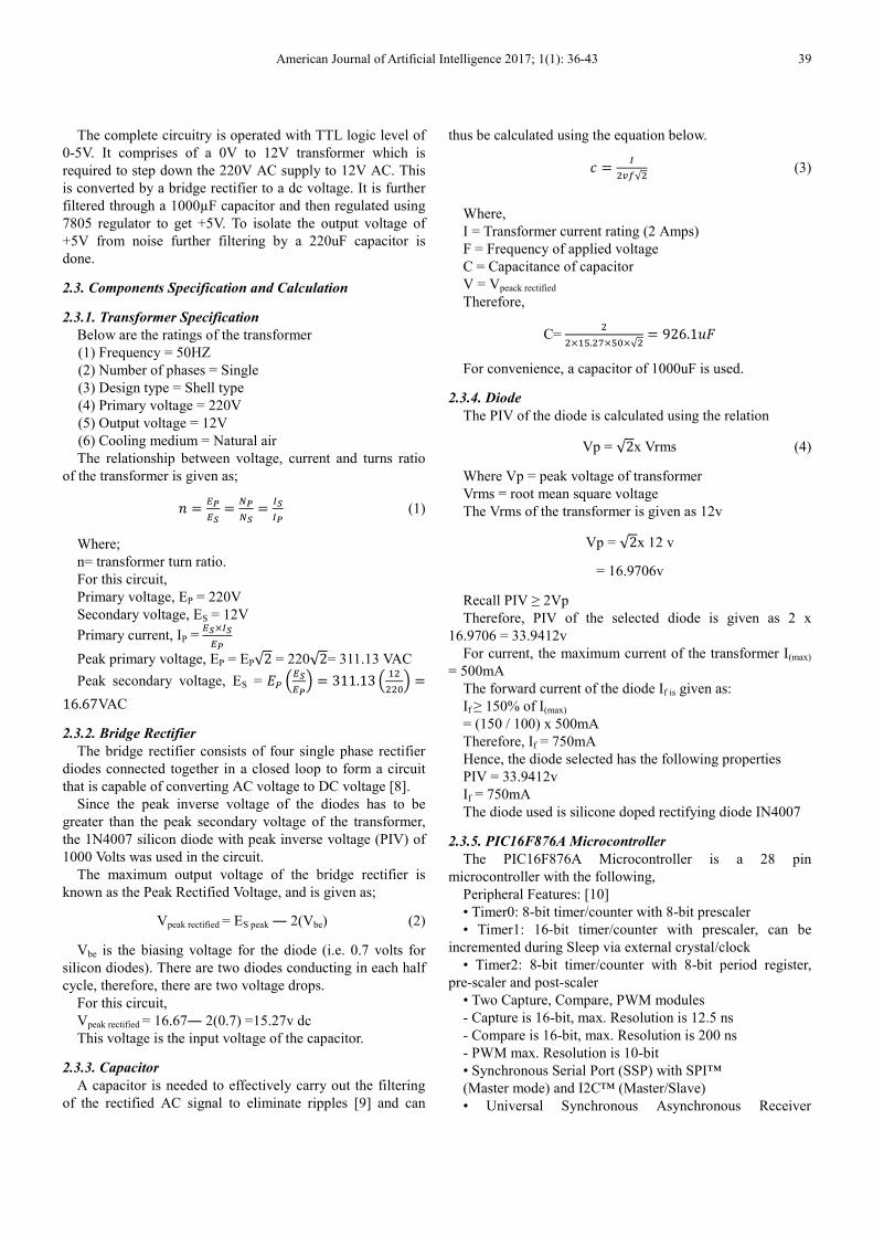
The complete circuitry is operated with TTL logic level of
0-5V. It comprises of a 0V to 12V transformer which is
required to step down the 220V AC supply to 12V AC. This
is converted by a bridge rectifier to a dc voltage. It is further
filtered through a 1000µF capacitor and then regulated using
7805 regulator to get +5V. To isolate the output voltage of
+5V from noise further filtering by a 220uF capacitor is
done.
2.3. Components Specification and Calculation
2.3.1. Transformer Specification
Below are the ratings of the transformer
(1) Frequency = 50HZ
(2) Number of phases = Single
(3) Design type = Shell type
(4) Primary voltage = 220V
(5) Output voltage = 12V
(6) Cooling medium = Natural air
The relationship between voltage, current and turns ratio
of the transformer is given as;
� = ����= ��
��= ��
�� (1)
Where;
n= transformer turn ratio.
For this circuit,
Primary voltage, EP = 220V
Secondary voltage, ES = 12V
Primary current, IP =������
Peak primary voltage, EP = EP√2 = 220√2= 311.13 VAC
Peak secondary voltage, ES = � ������ = 311.13 � ������ =16.67VAC
2.3.2. Bridge Rectifier
The bridge rectifier consists of four single phase rectifier
diodes connected together in a closed loop to form a circuit
that is capable of converting AC voltage to DC voltage [8].
Since the peak inverse voltage of the diodes has to be
greater than the peak secondary voltage of the transformer,
the 1N4007 silicon diode with peak inverse voltage (PIV) of
1000 Volts was used in the circuit.
The maximum output voltage of the bridge rectifier is
known as the Peak Rectified Voltage, and is given as;
Vpeak rectified = ES peak ― 2(Vbe) (2)
Vbe is the biasing voltage for the diode (i.e. 0.7 volts for
silicon diodes). There are two diodes conducting in each half
cycle, therefore, there are two voltage drops.
For this circuit,
Vpeak rectified = 16.67― 2(0.7) =15.27v dc
This voltage is the input voltage of the capacitor.
2.3.3. Capacitor
A capacitor is needed to effectively carry out the filtering
of the rectified AC signal to eliminate ripples [9] and can
thus be calculated using the equation below.
� = ����√� (3)
Where,
I = Transformer current rating (2 Amps)
F = Frequency of applied voltage
C = Capacitance of capacitor
V = Vpeack rectified
Therefore,
C= ��×��.��×��×√� = 926.1��
For convenience, a capacitor of 1000uF is used.
2.3.4. Diode
The PIV of the diode is calculated using the relation
Vp = √2x Vrms (4)
Where Vp = peak voltage of transformer
Vrms = root mean square voltage
The Vrms of the transformer is given as 12v
Vp = √2x 12 v
= 16.9706v
Recall PIV ≥ 2Vp
Therefore, PIV of the selected diode is given as 2 x
16.9706 = 33.9412v
For current, the maximum current of the transformer I(max)
= 500mA
The forward current of the diode If is given as:
If ≥ 150% of I(max)
= (150 / 100) x 500mA
Therefore, If = 750mA
Hence, the diode selected has the following properties
PIV = 33.9412v
If = 750mA
The diode used is silicone doped rectifying diode IN4007
2.3.5. PIC16F876A Microcontroller
The PIC16F876A Microcontroller is a 28 pin
microcontroller with the following,
Peripheral Features: [10]
• Timer0: 8-bit timer/counter with 8-bit prescaler
• Timer1: 16-bit timer/counter with prescaler, can be
incremented during Sleep via external crystal/clock
• Timer2: 8-bit timer/counter with 8-bit period register,
pre-scaler and post-scaler
• Two Capture, Compare, PWM modules
- Capture is 16-bit, max. Resolution is 12.5 ns
- Compare is 16-bit, max. Resolution is 200 ns
- PWM max. Resolution is 10-bit
• Synchronous Serial Port (SSP) with SPI™
(Master mode) and I2C™ (Master/Slave)
• Universal Synchronous Asynchronous Receiver

40 Okene David Ese and Okhueleigbe Emmanuel Ighodalo: An Intelligent System for Traffic
Control in Smart Cities: A Case Study
Transmitter (USART/SCI) with 9-bit address
Detection
• Parallel Slave Port (PSP) – 8 bits wide with external RD,
WR and CS controls (40/44-pin only)
• Brown-out detection circuitry for Brown-out Reset
(BOR)
Analog Features:
• 10-bit, up to 8-channel Analog-to-Digital Converter
(A/D)
• Brown-out Reset (BOR)
• Analog Comparator module with:
- Two analog comparators
- Programmable on-chip voltage reference (VREF) module
- Programmable input multiplexing from device inputs and
internal voltage reference
- Comparator outputs are externally accessible
Special Microcontroller Features:
• 100,000 erase/write cycle Enhanced Flash program
memory typical
• 1,000,000 erase/write cycle Data EEPROM memory
typical
• Data EEPROM Retention > 40 years
• Self-reprogrammable under software control
• In-Circuit Serial Programming™ (ICSP™) via two pins
• Single-supply 5V In-Circuit Serial Programming
• Watchdog Timer (WDT) with its own on-chip RC
oscillator for reliable operation
• Programmable code protection
• Power saving Sleep mode
• Selectable oscillator options
• In-Circuit Debug (ICD) via two pins
Figure 5. PIC 16f873A/876A Microcontroller.
Resistor Calculation
The resistor is connected to the micro controller to reduce
the amount of current.
Recall, from ohm’s law
R = � [11] (5)
V= 5V
I= 4mA
R1 = �
!"# = 1250ohms
For convenience, and availability a 1k ohms resistor was
used.
Therefore,
R1=R2=R3=R4=R5=R6=R7=R8=R9=R10…R20 = 1k ohms
2.3.6. LEDs
Table 1. LED specifications.
Colour Forward voltage (V) Forward current (mA)
Red 1.9 – 2.1 15
Yellow 1.9 – 2.1 15
Green 2.9 – 3.1 15
Resistors Calculation:
For red LED
Since five LEDs were used, the forward voltage will be
5 × 2v = 10v
Recall, from ohm’s law R �
�
Therefore,
R���&��
��"#� 133.3 ohms
For convenience, and availability in the market 220 ohms
resistor is used.
Therefore,
R1=R5=R9=R13= 220 ohms
For yellow LED;
Since five LEDs were used, the forward voltage will be
5 × 2v = 10v
Recall, from ohm’s law R �
�
Therefore,

American Journal of Artificial Intelligence 2017; 1(1): 36-43 41
R���&��
��"#� 133.3 ohms
For convenience, and availability in the market 220 Ohms
resistor is used.
Therefore,
R2=R6=R10=R14=220 ohms
For green LED;
Three LEDs were connected in series, and another two
LEDs were connected in series then connected in parallel.
3 × 3v = 9v
Recall, from ohm’s law R =
�
Therefore,
R ���&'
��"#� 200ohms
2 3( � 6(
Recall, from ohm’s law R =
�
Therefore,
R ���&)
��"#� 600ohms
For convenience, and availability a 670 Ohms resistor was
used.
Therefore,
R3=R7=R11=R15= 670 ohms
2.4. Choice of PIC16F876A Microcontroller and
Optocoupler
The reason for using PIC16F876A microcontroller over
ATMEGA microcontroller is that, the former is cheaper and
more readily available. As for the optocoupler, it is used to
provide coupling while ensuring electrical isolation between
its input and output [12]. Another purpose of an optocoupler
is to prevent rapidly changing voltages or high voltages on
one side of a circuit from distorting transmissions or
damaging components on the other side of the circuit.
2.5. Mode of Operation
Figure 4 shows the circuit diagram of the system. The
Transformer steps down the 220 v AC supply to 12 v AC.
This is rectified by the bridge rectifier, filtered by the
capacitors to remove ripples and regulated by the voltage
regulators to produce fixed value of 5 volts which is supplied
to the system.
IR sensors are placed on the intersections on the road at
fixed distances from the signal placed in the junction. The
time delay in the traffic signal is set based on the density of
vehicles on the roads. The IR sensors are used to sense the
number of vehicles on the road. According to the IR count,
microcontroller takes appropriate decisions as to which road
is to be given the highest priority and the longest time delay
for the corresponding traffic light.
2.6. Hard Ware Implementation
The Vero board is also called a strip board. It is a widely
used type of electronic prototyping board characterized by a
0.1-inch rectangular grid holes with parallel strips of copper
cladding running in one direction all the way across one side
of the board. The components were placed on the plain side
of the board, with their leads protruding through the holes.
The leads were then soldered to the copper tracks on the
other side of the board to make the desired connections. And
after soldering each unit, continuity test was carried out to
ensure that proper soldering was done.
2.7. Software Implementation
The PIC Microcontroller was programmed using
Embedded C language. The codes are as shown in the
Appendix. Simulation was done via Proteus software.
Figure 6. Construction of the Various Units.
42 Okene David Ese and Okhueleigbe Emmanuel Ighodalo: An Intelligent System for Traffic
Control in Smart Cities: A Case Study
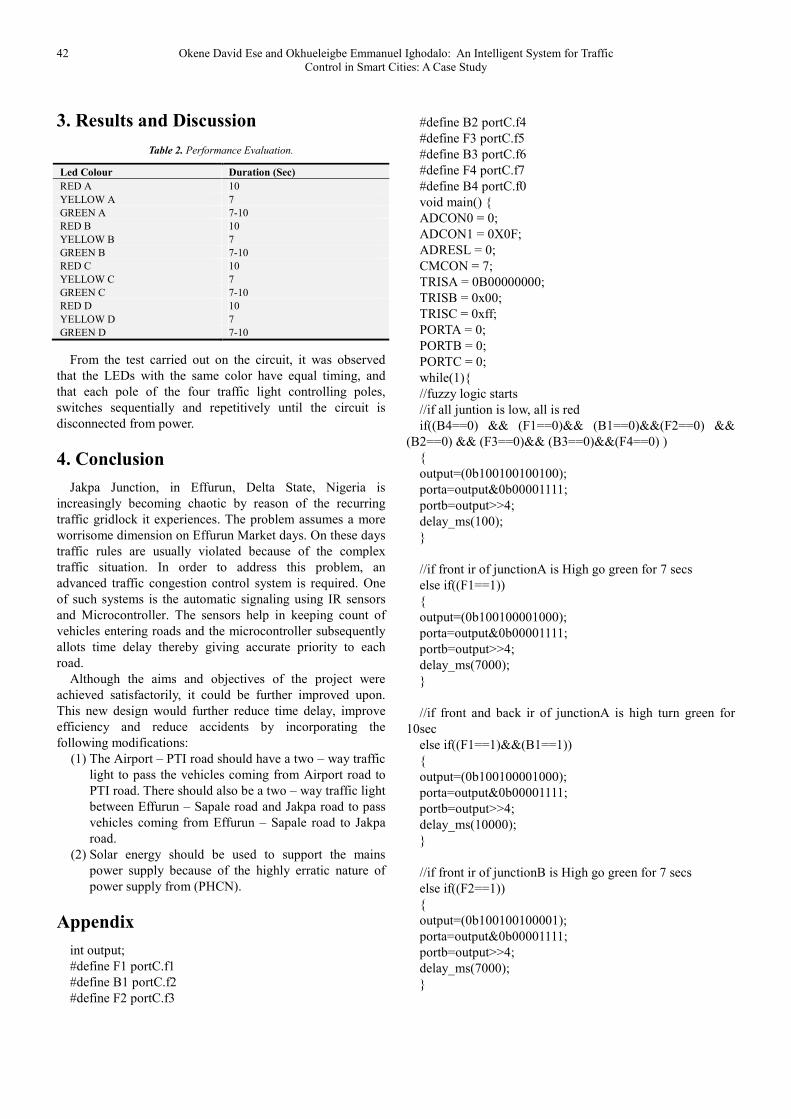
3. Results and Discussion
Table 2. Performance Evaluation.
Led Colour Duration (Sec)
RED A 10
YELLOW A 7
GREEN A 7-10
RED B 10
YELLOW B 7
GREEN B 7-10
RED C 10
YELLOW C 7
GREEN C 7-10
RED D 10
YELLOW D 7
GREEN D 7-10
From the test carried out on the circuit, it was observed
that the LEDs with the same color have equal timing, and
that each pole of the four traffic light controlling poles,
switches sequentially and repetitively until the circuit is
disconnected from power.
4. Conclusion
Jakpa Junction, in Effurun, Delta State, Nigeria is
increasingly becoming chaotic by reason of the recurring
traffic gridlock it experiences. The problem assumes a more
worrisome dimension on Effurun Market days. On these days
traffic rules are usually violated because of the complex
traffic situation. In order to address this problem, an
advanced traffic congestion control system is required. One
of such systems is the automatic signaling using IR sensors
and Microcontroller. The sensors help in keeping count of
vehicles entering roads and the microcontroller subsequently
allots time delay thereby giving accurate priority to each
road.
Although the aims and objectives of the project were
achieved satisfactorily, it could be further improved upon.
This new design would further reduce time delay, improve
efficiency and reduce accidents by incorporating the
following modifications:
(1) The Airport – PTI road should have a two – way traffic
light to pass the vehicles coming from Airport road to
PTI road. There should also be a two – way traffic light
between Effurun – Sapale road and Jakpa road to pass
vehicles coming from Effurun – Sapale road to Jakpa
road.
(2) Solar energy should be used to support the mains
power supply because of the highly erratic nature of
power supply from (PHCN).
Appendix
int output;
#define F1 portC.f1
#define B1 portC.f2
#define F2 portC.f3
#define B2 portC.f4
#define F3 portC.f5
#define B3 portC.f6
#define F4 portC.f7
#define B4 portC.f0
void main() {
ADCON0 = 0;
ADCON1 = 0X0F;
ADRESL = 0;
CMCON = 7;
TRISA = 0B00000000;
TRISB = 0x00;
TRISC = 0xff;
PORTA = 0;
PORTB = 0;
PORTC = 0;
while(1){
//fuzzy logic starts
//if all juntion is low, all is red
if((B4==0) && (F1==0)&& (B1==0)&&(F2==0) &&
(B2==0) && (F3==0)&& (B3==0)&&(F4==0) )
{
output=(0b100100100100);
porta=output&0b00001111;
portb=output>>4;
delay_ms(100);
}
//if front ir of junctionA is High go green for 7 secs
else if((F1==1))
{
output=(0b100100001000);
porta=output&0b00001111;
portb=output>>4;
delay_ms(7000);
}
//if front and back ir of junctionA is high turn green for
10sec
else if((F1==1)&&(B1==1))
{
output=(0b100100001000);
porta=output&0b00001111;
portb=output>>4;
delay_ms(10000);
}
//if front ir of junctionB is High go green for 7 secs
else if((F2==1))
{
output=(0b100100100001);
porta=output&0b00001111;
portb=output>>4;
delay_ms(7000);
}

American Journal of Artificial Intelligence 2017; 1(1): 36-43 43
//if front and back ir of junctionB is high turn green for
10sec
else if((F2==1)&&(B2==1))
{
output=(0b100100100001);
porta=output&0b00001111;
portb=output>>4;
delay_ms(10000);
}
//if front ir of junctionC is High go green for 7 secs
else if((F3==1))
{
output=(0b100001100100);
porta=output&0b00001111;
portb=output>>4;
delay_ms(7000);
}
//if front and back ir of junctionC is high turn green for
10sec
else if((F3==1)&&(B3==1))
{
output=(0b100001100100);
psorta=output&0b00001111;
portb=output>>4;
delay_ms(10000);
}
//if front ir of junctionD is High go green for 7 secs
else if((F4==1))
{
output=(0b001100100100);
porta=output&0b00001111;
portb=output>>4;
delay_ms(7000);
}
//if front and back ir of junctionD is high turn green for
10sec
else if((F4==1)&&(B4==1)){
output=(0b001100100100);
porta=output&0b00001111;
portb=output>>4;
delay_ms(10000);
}
//end of fuzzy
}
}
Acknowledgements
The authors wish to appreciate the support of Mr. Adams
Oladokun towards the success of this research.
References
[1] R. Linganagouda, R. Pyinti and P. Anusuya, "Automatic Intelligent Traffic Control System," International Journal of Advanced Research in Electrical, Electronics and Instrumentation Engineering, vol. V, no. 7, pp. 5902-5906, 2016.
[2] A. Chattaraj, S. Bansal and A. Chandra, "An intelligent traffic control system using RFID," IEEE Potentials, vol. 28, no. 3, pp. 40-43, May.
[3] S. Misra, "Design of Traffic Light Controller Using Timer Circuit," in Proceedings of IEEE National Student Paper and Circuit Design Contest, Kolkotta, 2012.
[4] K. Vidhya and B. Bazila, "Density Based Traffic Signal System," International Journal of Innovative Research in Science, Engineering and Technology, vol. 3, no. 3, pp. 2218-2222, 2014.
[5] A. Pinto and G. Mattioli, "Intelligent Traffic Lights Control System using Fuzzy Logic," in SAE Brasil International Congress and Display, Sao Paulo, 2014.
[6] T. Vishakha, J. Snehal, S. Sananaj and P. Poonam, "Design of Smart Traffic Light Controller Using Embedded System," IOSR Journal of Computer Engineering (IOSR-JCE), vol. X, no. 1, pp. 30-33, 2013.
[7] A. O. James, "An Intelligent Traffic Light Control System," International Academic Journal of Information Systems and Technology, vol. 1, no. 5, pp. 1-17, 2015.
[8] Physics, Radio and Electronics, "Electronic Devices and Circuits," 20 May 2017. [Online]. Available: http://www.physics-and-radio-electronics.com/electronic-devices-and-circuits/rectifier/bridgerectifier.html.
[9] B. Theraja and A. Theraja, A texbook of Electrical Technology, India: Chand, 2005.
[10] Microchip, "Products," 20 May 2017. [Online]. Available: http://www.microchip.com/wwwproducts/en/PIC16F876A.
[11] H. Edward, J. Hiley, I. Smith and K. Brown, Hughes Electrical/Electronic Technology, Harlow: Pearson Prentice Hall, 2008.
[12] A. Godse and U. Bakshi, Electronic Devices and Circuits, Pune: Technical Publications, 2009.