AN INITIAL LOOK AT ADJACENT BAND INTERFERENCE …
13
412TW-PA-16293 AN INITIAL LOOK AT ADJACENT BAND INTERFERENCE BETWEEN AERONAUTICAL MOBILE TELEMETRY AND LONG-TERM EVOLUTION WIRELESS SERVICE KIP TEMPLE AIR FORCE TEST CENTER EDWARDS AFB, CA 4 July 2016 4 1 2 T W DISTRIBUTION A. Approved for public release; distribution is unlimited. 412TW-PA-16293 412TH TEST WING EDWARDS AIR FORCE BASE, CALIFORNIA AIR FORCE MATERIEL COMMAND UNITED STATES AIR FORCE
Transcript of AN INITIAL LOOK AT ADJACENT BAND INTERFERENCE …

412TW-PA-16293
AN INITIAL LOOK AT ADJACENT BAND INTERFERENCE BETWEEN
AERONAUTICAL MOBILE TELEMETRY AND LONG-TERM EVOLUTION WIRELESS
SERVICE
KIP TEMPLE
AIR FORCE TEST CENTER EDWARDS AFB, CA
4 July 2016
4 1 2TW
DISTRIBUTION A. Approved for public release; distribution is unlimited. 412TW-PA-16293
412TH TEST WING EDWARDS AIR FORCE BASE, CALIFORNIA
AIR FORCE MATERIEL COMMAND UNITED STATES AIR FORCE

REPORT DOCUMENTATION PAGE Form Approved
OMB No. 0704-0188 Public reporting burden for this collection of information is estimated to average 1 hour per response, including the time for reviewing instructions, searching existing data sources, gathering and maintaining the data needed, and completing and reviewing this collection of information. Send comments regarding this burden estimate or any other aspect of this collection of information, including suggestions for reducing this burden to Department of Defense, Washington Headquarters Services, Directorate for Information Operations and Reports (0704-0188), 1215 Jefferson Davis Highway, Suite 1204, Arlington, VA 22202-4302. Respondents should be aware that notwithstanding any other provision of law, no person shall be subject to any penalty for failing to comply with a collection of information if it does not display a currently valid OMB control number. PLEASE DO NOT RETURN YOUR FORM TO THE ABOVE ADDRESS. 1. REPORT DATE (DD-MM-YYYY)
04-07-2106 2. REPORT TYPE Technical
3. DATES COVERED (From - To) 06-01-2016- 07-04/2016
4. TITLE AND SUBTITLE AN INITIAL LOOK AT ADJACENT BAND INTERFERENCE BETWEEN AERONAUTICAL MOBILE TELEMETRY AND LONG-TERM EVOLUTION WIRELESS SERVICE
5a. CONTRACT NUMBER 5b. GRANT NUMBER 5c. PROGRAM ELEMENT NUMBER
6. AUTHOR(S) Kip Temple
5d. PROJECT NUMBER 5e. TASK NUMBER 5f. WORK UNIT NUMBER 7. PERFORMING ORGANIZATION NAME(S) AND ADDRESS(ES) AND ADDRESS(ES)
Kip Temple, 412 TENG/ENI
8. PERFORMING ORGANIZATION REPORT NUMBER
412TW-PA-16293
9. SPONSORING / MONITORING AGENCY NAME(S) AND ADDRESS(ES)
10. SPONSOR/MONITOR’S ACRONYM(S) N/A
11. SPONSOR/MONITOR’S REPORT NUMBER(S)
12. DISTRIBUTION / AVAILABILITY STATEMENT DISTRIBUTION A. +Approved for public release A: distribution is unlimited. 13. SUPPLEMENTARY NOTES CA: Air Force Test Center Edwards AFB CA CC: 012100
14. ABSTRACT With the Federal Communications Commission (FCC) Advanced Wireless Services (AWS-3) auction of frequencies in the 1695-1710 MHz, 1755-1780MHz, and 2155-2180MHz bands, users of the Aeronautical Mobile Telemetry (AMT) band from 1755-1850MHz, known as Upper L-Band, could be greatly affected. This paper takes an initial look at how the 1755-1780MHz band will be used by the cellular carriers and presents some preliminary testing results of adjacent channel (band) interference that could be experienced by AMT users. This paper should be considered as a stepping-off point for future interference discussions, required analysis, and further testing.
15. SUBJECT TERMS Adjacent Channel Interference, ACI, LTE-A, LTE, PCM/FM, SOQPSK-TG, ARTM CPM, AWS-3, User Equipment, UE, Evolved Node B, eNodeB, Resource Blocks 16. SECURITY CLASSIFICATION OF: Unclassified
17. LIMITATION OF ABSTRACT
18. NUMBER OF PAGES
19a. NAME OF RESPONSIBLE PERSON 412 TENG/EN (Tech Pubs)
a. REPORT Unclassified
b. ABSTRACT Unclassified
c. THIS PAGE Unclassified None 13
19b. TELEPHONE NUMBER (include area code)
661-277-8615 Standard Form 298 (Rev. 8-98)
Prescribed by ANSI Std. Z39.18

AN INITIAL LOOK AT ADJACENT BAND INTERFERENCE BETWEEN AERONAUTICAL MOBILE TELEMETRY AND
LONG-TERM EVOLUTION WIRELESS SERVICE
Kip Temple Air Force Test Center, Edwards AFB CA
ABSTRACT With the Federal Communications Commission (FCC) Advanced Wireless Services (AWS-3) auction of frequencies in the 1695-1710 MHz, 1755-1780MHz, and 2155-2180MHz bands, users of the Aeronautical Mobile Telemetry (AMT) band from 1755-1850MHz, known as Upper L-Band, could be greatly affected. This paper takes an initial look at how the 1755-1780MHz band will be used by the cellular carriers and presents some preliminary testing results of adjacent channel (band) interference that could be experienced by AMT users. This paper should be considered as a stepping-off point for future interference discussions, required analysis, and further testing.
KEY WORDS Adjacent Channel Interference, ACI, LTE-A, LTE, PCM/FM, SOQPSK-TG, ARTM CPM, AWS-3, User Equipment, UE, Evolved Node B, eNodeB, Resource Blocks

INTRODUCTION “On January 29, 2015, the Federal Communications Commission completed an auction of Advanced Wireless Service licenses in the 1695-1710 MHz, 1755-1780 MHz, and 2155-2180 MHz bands (collectively, the “AWS-3” bands). This auction, designated as Auction 97, raised in net bids a total of $41,329,673,325, with 31 bidders winning a total of 1,611 licenses. With the reallocation of the 1695-1710 MHz and 1755-1780 MHz bands, most of the federal systems will relocate out of the bands.” [1] Times are changing for users of AMT spectrum as new neighbors will be showing up in the form of cellular carriers. In the past AWS-3 AMT users have been worried primarily about in-band interferers, addressed within IRIG-106 [2, 5] as recommendations for channel spacing of AMT waveforms [8, 9]. Benchtop characterization of the adjacent band interferers for AWS-3 spectrum typically has not been done due to various reasons. Either the signals are not a direct interference threat (due to specific geographical separation, pointing azimuths for receive antennas, frequency scheduling, etc.) or the required interference information as provided by users was not adequate for performing an interference analysis in accordance with the protection criteria of Recommendation ITU-R M.1459 [3]. With the proliferation of cellular services coupled with public demand for the service and the AWS-3 auction, AMT ranges will be presented with new challenges. Figure 1 graphically shows two potential interference scenarios for AMT ranges given an implementation of cellular service in the AWS-3 band. The first is the “near-far” scenario, the second is ground station antenna side lobe interference. How will the new commercial neighbors affect AWS-3 AMT operations? If interference is present, what conditions should be avoided? Are there mitigation techniques, such as receive antenna feed filtering, that may mitigate the interference? The answers to these questions make necessary an improved understanding of the interferers that can be obtained only by hands-on measurements. This work will attempt to provide the basis to start these conversations and hopefully provide the reader with more information on what to look for at ground stations once AWS-3 enabled handsets are fielded by the carriers.
Figure 1 – The Interference Scenarios
AWS-3 CELLULAR SERVICE
In order to characterize any adjacent channel (adjacent band) interference from a neighboring cellular service, an understanding of how the spectrum is allocated and a basic understanding of how the service works are required. Per the guidelines in the AWS-3 auction, portions of the bands were paired with differing bandwidths. Of concern to AMT users, the upper portion of the AWS-3 band is partitioned into a 10MHz channel making this channel (1770-1780MHz) [1] directly adjacent to the lower part of the AMT band Upper L-Band (1780-1850MHz) [5]. The AWS-3/AMT boundary is at 1780MHz. Figure 2 shows the channel pairings and the bandwidths

in the AWS-3 spectrum. Note that the 10MHz channel at the AMT band edge allocates 1770-1780MHz to what is commonly called the uplink, or the user equipment (UE) to base station (Evolved Node B or eNodeB) link. Conversely, the paired downlink (eNodeB to UE) operates between 2170-2180MHz. AWS-3 spectrum will only be used for 3GPP 4G applications or what typically is referred to as LTE or LTE-A by the general public [4].
Figure 2 - AWS-3 Band Plan
Understanding how an entire LTE cellular system works is beyond the scope of this paper. What is of concern is the portion of the LTE system that could potentially interfere with an AMT receive station, the physical layer. The uplink utilizes Single Carrier Frequency Division Multiple Access (SC-FDMA) which is a unique orthogonal frequency-division multiplexed (OFDM) like multi-carrier scheme that reduces peak-to-average power ratio (PAPR) in the signal. Minimizing PAPR is important for the UE handset as less PAPR translates to more battery life [6]. The capacity a user is allocated is typically determined by demand on the channel (total capacity), user demand (current need), and channel condition. The LTE uplink uses a multiple access scheme where each UE uses a pre-allocated set of resource blocks (RB). A resource block is a time-frequency block and is the basis for resource allocation for both the uplink and downlink. Since SC-FDMA is a multi-carrier scheme, the carriers are modulated with one of three different modulation schemes, the selection being dependent upon a combination of channel condition and user demand. The three schemes are Quadrature Phase Shift Keying (QPSK), 16-Quadrature Amplitude Modulation (16-QAM), and 64-QAM.
ADJACENT CHANNEL (BAND) INTERFERENCE (ACI) RATIONALE For typical “in-band” ACI testing based upon IRIG-106 recommendations [7], the interfering signal is 20dB above the victim signal (i.e. the AMT signal). An acceptable degradation level in the performance of the victim receiver is assessed in terms of energy per bit to noise power spectral density ratio (Eb/No). A difference of 1dB of required Eb/No to achieve an error rate of 1x10⁻⁵ as the victim is moved closer to the interferer is the threshold interference criterion. (Note: Required BER is dependent upon the type of testing and can range from 1e-3 to in excess of 1e-7. A BER = 1e-5 was chosen for this particular testing.) For in-band testing, the interferer can be moved as close in frequency as required to attain the 1dB of degradation. For adjacent band testing, this is not the case as there is a fixed frequency boundary between the AMT signal and the interferer. The testing described here-in was to determine if interference could be expected from an adjacent band interferer rather than an adjacent in-band interferer as is the norm in AMT

operations. The difference between in-band and adjacent band, specifically in this case, is the fixed frequency boundary at 1780MHz. The interferer, LTE in a 10MHz bandwidth, is fixed in frequency. The AMT signal is also fixed in frequency as band-edge back-off from 1780MHz has a fixed center frequency based upon data rate and modulation mode calculated in accordance with the recommended procedures in IRIG-106 [5]. Since both victim and interferer are fixed in frequency, the only way to introduce interference into the victim AMT signal is to vary the Carrier (the AMT signal) to Interference (the LTE signal) ratio (C/I). For the AMT victim signal, all three IRIG-106 modulation schemes (PCM/FM, SOQPSK-TG, ARTM CPM) were tested at various data rates (1, 5, 10, 15Mbps). The pairing of modulation mode and data rates is shown in Table 1. For the LTE interfering signal, the generation matrix is considerably more complicated. Controllable parameters are the number of user (UE) handsets (1, 2, 3, 4), the resource block allocation for each UE (50 total RBs for a 10MHz channel), addition of control channels, and the modulation scheme for each UE.
Victim (AMT)
Bit Rate, Modulation Mode 1, 5Mbps (PCM/FM) 1, 5, 10Mbps (SOQPSK) 5, 10, 15Mbps (ARTM CPM)
Telemetry Receiver 8 IF SAW filters, selected per data rate and modulation mode
Interferer (LTE) Number of User Equipment (UE) 1, 2 Resource Blocks 50 Total, Random Allocation Control Channels 2 or 4 Modulation QPSK, 16-QAM, 64-QAM
Table 1 – ACI Test Parameters In order to achieve a realizable test matrix for the LTE signal, several assumptions were made:
• Only QPSK and 16-QAM were the chosen modulations for the LTE signal. The reasoning is that for AMT interference the UE’s will be near AMT ground stations. AMT ground stations operating in 1780-1850MHz are typically in remote geographical areas which translates to long link distances from UEs to eNodeBs. Given this longer link distance, the assumption was made that the transmission channel would not support 64-QAM modulation.
• No more than two UE’s would be in close proximity to the AMT ground station. • The occupied bandwidth (OBW) of the resulting LTE signal is given in order to provide
the reader an idea of how much of the 10MHz LTE channel is allocated. • Control channels were assumed to be at edges of the spectrum, i.e. RB 1 & 2 and RB 49
& 50, so these were not allocated during the testing.

# of UEs RBs RB/UE Modulation OBW (MHz) 1 46 46 QPSK 9 1 46 46 16-QAM 9 1 23 23 QPSK 4.5 1 23 23 16-QAM 4.5 1 10 10 QPSK 1.8 2 46 23 QPSK (both) 9 2 46 23 16-QAM (both) 9 2 20 10 16-QAM (both) 9
Table 2 – LTE Parameters AMT Band Edge Back-Off When scheduling the use of center frequencies near the edge of AMT bands is required, IRIG-106 (Chapter 2, Section 2.4.7) [5] provides the frequency manager a recommendation on how to locate the signal. Once the modulation mode and data rate are known, the calculation of the AMT center frequency can be made. Table 3 shows the modulation mode, data rate, amount of back off required, and resulting center frequency. As an example, the band-edge is known to be located at 1780MHz, for SOQPSK-TG at 10Mbps the center frequency would be tuned to 1780MHz + 9MHz = 1789MHz. Also included in Table 3 is the bandwidth of the intermediate filter (IF) filter chosen by the telemetry receiver given the modulation mode and data rate. This filter plays a key role in the amount of interference encountered by the received signal.
Modulation Data Rate Back-Off (MHz) Center Frequency Receiver IFBW PCM/FM 1Mbps 2.5MHz 1782.5MHz 2MHz PCM/FM 5Mbps 10MHz 1790MHz 10MHz
SOQPSK-TG 1Mbps 1.5MHz 1781.5MHz 1MHz SOQPSK-TG 5Mbps 5MHz 1785MHz 10MHz SOQPSK-TG 10Mbps 9MHz 1789MHz 20MHz ARTM CPM 5Mbps 4MHz 1784MHz 10MHz ARTM CPM 10Mbps 7MHz 1787MHz 20MHz ARTM CPM 15Mbps 10MHz 1790MHz 20MHz
Table 3 – Band Edge Back-Off for AMT Waveforms Resource Blocks A resource block (RB) is the smallest unit of resource that can be allocated to a user and is the fundamental scheduling unit in an LTE system. The total number of resource blocks available in a 10MHz LTE channel is 50. These 50 blocks are allocated to the UE(s) to support the uplink data requirements of each user in the system. The location of the allocated RBs have a direct relationship to where the UE will transmit within the 10MHz of spectrum. RB 1 is located at the bottom of the 10MHz, RB 50 is located at the top of the 10MHz. In order to keep the test matrix relatively simple with an attempt toward a real-world allocation, only a couple of RB/UE allocations where used. Figure 3 illustrates these allocations.

Figure 3 – Resource Block per User Equipment Allocations
LAB TEST CONFIGURATION
The lab test configuration consisted of generating of the LTE and AMT signals, isolating and combining them, and then splitting the combined signal for observation, measurement, detection, and finally interference analysis. For signal generation, a Rohde & Schwarz SMW200A Vector Signal Generator (VSG) was used. This specific VSG was equipped with the “Beyond 3G Standards” option for EUTRA/LTE-A configuration and signal generation. Reference AMT waveforms (PCM/FM, SOQPSK-TG, ARTM CPM) were loaded into the VSG and selected via the Arbitrary Waveform Generator. This VSG has two individual RF modulators allowing this single generator to produce both test signals. For this testing, RF path 1 (I/Q modulator #1) was dedicated to generating the LTE signal while RF path 2 (I/Q modulator #2) was dedicated to generating the AMT signal. Both signals were then routed through 20dB of reverse isolation to ensure no intermodulation products were created, biasing the testing results. After isolation the signals were combined then split again with one path going to the AMT reference receiver, a Quasonix RDMS, while the other path went to the Rohde & Schwarz FSW Spectrum and Signal Analyzer equipped with the Multi-Standard Radio Analysis (LTE) package. (Note: Though not used in this testing, this analysis package will be useful for any future AMT to LTE interference testing). The reference receiver was configured for the AMT waveform under test and connected to a bit error rate tester (HP3784A). Figure 4 shows a block diagram of the lab test configuration. Care had to be taken setting the levels of the LTE and AMT waveforms. At higher amplitude levels of the LTE signal, out of band distortion was present. This distortion fell into the AMT band and initially biased the test results. To mitigate this effect, the amplitude of the LTE signal was then adjusted based upon the required C/I referenced to the level of the AMT waveform. Since a reduced amplitude in the LTE waveform reduced the distortion, the level of the AMT signal was minimized. The AMT waveform level was set approximately 20dB above where additive system noise was causing the referenced bit error rate of 1e-5. This was done for each AMT waveform. C/I was precisely set by removing the modulation, verifying the ratio on the spectrum analyzer, then double checking that ratio by verifying the amplitude of each signal path in the VSG.

Figure 4 – Lab Test Block Diagram
RESULTS
Adjacent band testing revealed some interesting results. Generally speaking, the configuration of the interfering LTE signal in terms of the number of users, resource blocks, and modulation mode really didn’t make much of a difference as long as there were resource blocks allocated at the upper part of the bandwidth adjacent to 1780MHz. Slightly greater degradation was observed when the modulation was 16-QAM, possibly due to the greater amplitude variation of the signal. But for the most part, if the spectrum next to 1780MHz was illuminated the interference test results were very consistent. In all, 45 test scenarios using a combination of the parameters in Tables 1 and 2 were tested. Figures 5 through 7 show spectra of some of the test cases for each AMT waveform. In all of the spectrum analyzer screen captures, the AMT signal is to the right of 1780MHz, the LTE signal is to the left of 1780MHz.
Figure 5 – PCM/FM vs. LTE

Figure 6 – SOQPSK-TG vs. LTE
Figure 7 – ARTM CPM vs. LTE
The results of the 45 test scenarios are summarized in Table 4. For PCM/FM at 5Mbps, the calculated band-edge back-off of 10MHz from 1780MHz provided enough separation that no interference was encountered with a C/I up to -50dB (the interferer being 50dB higher than the victim). For 1Mbps, no interference was observed up to C/I = -35dB. Because the levels were low enough to mitigate out of band distortion from the LTE signal generation (mentioned above), higher C/I values in this case were not possible as lowering the victim level brought the amplitude to a point where additive system noise was affecting the results.

There were varied results for SOQPSK-TG based upon bit rate. For 5Mbps the calculated back-off of 5MHz was enough for C/I = -30dB to cause the referenced bit error rate of 1e-5. The calculated back-off for 1Mbps and 10Mbps resulted in C/I values of -20dB and -24dB respectively. It is curious that a C/I difference of 10dB between 1Mbps and 5Mbps in order to achieve the same level of performance degradation was observed. The band-edge back-off calculation of 7MHz for ARTM CPM at 10Mbps does not meet the initial IRIG-106 ACI criterion of -20dB for a BER = 1e-5 and had to be reduced to -18dB. Again, a C/I difference of 10dB was observed between data rates of 10Mbps and 15Mbps. The wide range in C/I values is curious. Two potential mechanisms may be in play here. The first is band-edge back-off. The band-edge back-off numbers in Table 3 are rounded to the nearest 500kHz but are not channelized using 500kHz steps as is normal practice. Increasing (or decreasing) spacing another 500kHz may have brought more consistent C/I results. The second mechanism is the IF filter. Only 8 surface acoustic wave (SAW) filters are available in the telemetry receiver and selecting which one to use is a compromise between ACI and BER performance. It is possible, based upon data rate, that one filter provided more selectivity resulting in a greater (more negative value) C/I.
Modulation/Data Rate C/I (dB) BER PCM/FM, 1Mbps -35 0 PCM/FM, 5Mbps -50 0 SOQPSK, 1Mbps -20 1e-5 SOQPSK, 5Mbps -30 1e-5 SOQPSK, 10Mbps -24 1e-5
ARTM CPM, 5Mbps -22 1e-5 ARTM CPM, 10Mbps -18 1e-5 ARTM CPM, 15Mbps -28 1e-5
Table 4 – Summary of Test Results
What do the C/I values in Table 4 mean in the real-world? A simple calculation may help with this understanding. Referring back to the near-far interference scenario (illustrated in Figure 1) and making assumptions about both the AMT and LTE links, the distance required from UE to AMT receive antenna can be calculated for that C/I. AMT Link Assumptions Assume nominal values of an EIRP of 5W (+37dBm) and a link range of 80NM (~150km). LTE Link Assumptions Assume the UE requires a worst case EIRP of 25dBm in order to close the UE to eNobeB link and that the UE is within the main beam of the AMT receive antenna. With these assumptions, the distance the UE is from the AMT receive station, given a C/I value, can be calculated. Table 5 shows the results of these calculations and illustrates the wide range of “keep out zones” around an AMT ground station based upon the given assumptions.
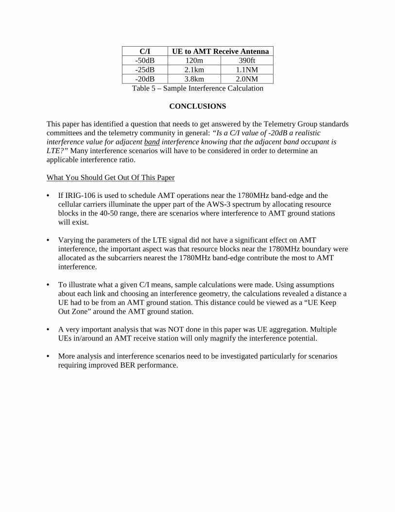
C/I UE to AMT Receive Antenna -50dB 120m 390ft -25dB 2.1km 1.1NM -20dB 3.8km 2.0NM
Table 5 – Sample Interference Calculation
CONCLUSIONS This paper has identified a question that needs to get answered by the Telemetry Group standards committees and the telemetry community in general: “Is a C/I value of -20dB a realistic interference value for adjacent band interference knowing that the adjacent band occupant is LTE?” Many interference scenarios will have to be considered in order to determine an applicable interference ratio. What You Should Get Out Of This Paper • If IRIG-106 is used to schedule AMT operations near the 1780MHz band-edge and the
cellular carriers illuminate the upper part of the AWS-3 spectrum by allocating resource blocks in the 40-50 range, there are scenarios where interference to AMT ground stations will exist.
• Varying the parameters of the LTE signal did not have a significant effect on AMT interference, the important aspect was that resource blocks near the 1780MHz boundary were allocated as the subcarriers nearest the 1780MHz band-edge contribute the most to AMT interference.
• To illustrate what a given C/I means, sample calculations were made. Using assumptions
about each link and choosing an interference geometry, the calculations revealed a distance a UE had to be from an AMT ground station. This distance could be viewed as a “UE Keep Out Zone” around the AMT ground station.
• A very important analysis that was NOT done in this paper was UE aggregation. Multiple
UEs in/around an AMT receive station will only magnify the interference potential. • More analysis and interference scenarios need to be investigated particularly for scenarios
requiring improved BER performance.

ACKOWLEDGEMENTS A special thanks to the Spectrum Relocation Fund managed by Bobbie Wheaton, without the support from this program the work could not have been accomplished. The author would also like to thank Tim Chalfant, Bob Selbrede, Dr. Dan Jablonski, and Ken Keane for providing valuable insight and support throughout the generation of this paper.
REFERENCES 1. National Telecommunications & Information Administration (NTIA), ”AWS-3 Transition”,
https://www.ntia.doc.gov/category/aws-3-transition
2. Secretariat, Range Commander Council, “Frequency Considerations for Telemetry”, RCC Document IRIG-106 Appendix A
3. Recommendation ITU-R M.1459, “Protection Criteria for Telemetry Systems in the
Aeronautical Mobile Service and Mitigation Techniques to Facilitate Sharing with Geostationary Broadcasting-Satellite and Mobile-Satellite Services in the Frequency Bands 1452-1525MHz and 2310-2360MHz”, http://www.itu.int/rec/R-REC-M.1459/en
4. LTE/LTE-A System Specifications and Standards, 3rd Generation Partnership Project, TS
36.xxx, http://www.3gpp.org/about-3gpp/about-3gpp 5. Secretariat, Range Commander Council, “Transmitter and Receiver Systems”, RCC
Document IRIG-106 Chapter 2 6. National Instruments, “Introduction to LTE Device Testing”, www.ni.com/rf-academy 7. Temple, Kip, “Adjacent Channel Interference Criteria for Aeronautical Telemetry Operation
with the TTNT System”, International Telemetry Conference Proceedings, October 2009 8. Law, Gene, “Recommended Minimum Telemetry Frequency Spacing with CPFSK, CPM,
SOQPSK, and FQPSK Signals”, International Telemetry Conference Proceedings, Oct 2003 9. Law, Gene, “Adjacent Channel Interference Measurements with CPFSK, CPM, and FQPSK-
B Signals”, International Telemetry Conference Proceedings, Oct 2002