An Information and Activity Booklet - NASA · ed into two parts. The first presents basic...
38
An Information and Activity Booklet Grades 9-12 October 1998 A product of the Rossi X-ray Timing Explorer Learning Center http://rxte.gsfc.nasa.gov/docs/xte/learning_center/ NP-1998-01-002-GSFC
Transcript of An Information and Activity Booklet - NASA · ed into two parts. The first presents basic...

An Information and Activity Booklet Grades 9-12
October 1998
A product of the Rossi X-ray Timing Explorer Learning Center
http://rxte.gsfc.nasa.gov/docs/xte/learning_center/
NP-1998-01-002-GSFC


The Rossi X-ray Timing Explorer
Learning Center
PRESENTS:
Written by:Maggie Masetti
NASA/GSFC/RSTXGreenbelt, MD
This booklet can be used in conjunction with the RXTE Learning Center website.An on-line version of this booklet as well as the RXTE model is available at:
http://rxte.gsfc.nasa.gov/docs/xte/learning_center/
NP-1998-01-002-GSFC
Shedding A New LightOn the Universe!


Introduction:
Someone once said that distance doesn’t really make us any smaller, just part of a larger picture. Too often, we let sci-ence scare and overwhelm us, when really, using science to learn new things about the Universe can help us not only to see the larger picture more clearly, but also to see where we fit into it. The sense of wonder and possibility that the Uni-verse engenders in us all can never be killed by science; on the contrary, science has shown that there will always be new marvels to discover and explore. We hope this booklet will provide you with new ideas to investigate.
On our web site, you can find out about the latest discover-ies made by RXTE, browse through our collection of imag-es and movies, and even access lesson plans written by sci-ence and math teachers! Our newest feature helps you to access Real Time data from the All-Sky Monitor (ASM), one of the instruments mounted on RXTE. This feature, called “Tour the ASM Sky,” includes a small introduction to the ASM instrument and has a page where you can access lesson plans specific to this data! Among the many other things on our site, you will also find a colorful on-line ver-sion of everything contained in this booklet.
Because we didn’t want to make any assumptions about the reader’s prior knowledge, this booklet is unofficially divid-ed into two parts. The first presents basic information about the electromagnetic spectrum and multiwavelength astronomy, with an emphasis on X-ray astronomy. The second describes X-ray detectors at a more advanced level. There is also an introduction to the Rossi X-ray Timing Explorer (RXTE) and its contributions to science. We hope this booklet will illustrate why multiwavelength astronomy is important, and how the RXTE is a useful tool with which to explore the Universe. While this booklet does not contain lesson plans, we have included suggestions for activities that can be done by students and interested adults alike, in the classroom or at home.
Thanks to J. Allie Cliffe, not only for her useful input, but for the many activities contained in this booklet that were created in whole or in part by her. Thanks also to Dr. James Lochner for his help and encouragement, to Rachelle Andrews, a teacher at Parkdale High School, Riverdale, MD, for her comments and advice, and to the many people who proofread this booklet.
Format:
The Rossi X-ray Timing Explorer Learning Center
Acknowledgements

The Electromagnetic Spectrum .................................................................. 1 Electromagnetic Spectrum Activity ........................................................... 1 What If We Could See Infrared Light? ...................................................... 2 X-ray Vision ............................................................................................... 2 Multiwavelength Activity. ......................................................................... 2 The Energetic Universe ............................................................................. 3 Energy, Frequency, and Wavelength Activity ............................................ 3 A Telescope For All Occasions .................................................................. 5 The Multiwavelength Milkyway ............................................................... 6 The Crab Nebula in Different Energies ..................................................... 7 X-ray Astronomy ....................................................................................... 8 Imaging ...................................................................................................... 8 Spectroscopy .............................................................................................. 9 Light Curves .............................................................................................. 9 X-ray Detection Activity .......................................................................... 10 Graphing Activity .................................................................................... 10 Measuring Photon Energies ..................................................................... 11 Satellites and Their Parts ......................................................................... 11 Satellite Activity ...................................................................................... 12 The Rossi X-ray Timing Explorer ........................................................... 13 What Does RXTE Look At? .................................................................... 14 What Does RXTE Look At Activity .........................................................15 RXTE Discoveries ................................................................................... 16 Appendix 1 ............................................................................................... 17Resources ................................................................................................. 18Footnotes .................................................................................................. 20Build Your Own Model of RXTE ........................................................... 21
TaBLE OF CONTENTS

Although it would seem that the human eye gives us a pretty accurate view of the world, we are literally blind to much of what surrounds us. A whole Universe of color exists, only a thin band of which our eyes are able to detect; an example of this visible range of color is the familiar concept of a rainbow or a spectrum. The optical spectrum ranges in color from reds and oranges up through blues and purples. Each of these colors actually corresponds to a different energy of light. The colors or energies of light that our eyes cannot see also have names that are familiar to us. We listen to radios, we have X-rays taken of our broken bones, we eat food heated in microwaves, yet many times we do not realize that radio, X-ray, and microwave are actually energies of light! The entire range of energies of light, including both light we can see and light we cannot see, is called the electromagnetic spectrum. It includes, from highest energy to lowest: gamma-ray, X-ray, ultraviolet, optical, infrared, microwave, and radio wave. Because we can only see visible light, we are put at a disadvantage, for the Universe is actively emitting light at all these different energies.
Suppose you were studying and trying to understand a kind of flower - possibly tulips. Suppose also that you could ONLY detect things that are green. What parts of the tulip would you know about if you could only detect things that are green? What parts of the tulip would you not be aware of? Would tulips look the same or different in the summer as they do in winter? How would you hypothesize your tulips get nutrients? Repro-duce? Grow? Since you can only detect green, what other methods of investigation would you have to use?
Plant biology would be quite different if we could only detect things that were green! Do you think that we could understand as much as we do about plants? If we could not detect flowers, it would be difficult to know how plants reproduce! If we could not see plant roots, we would be hindered from learning how plants get nutrition. Soil is not green either, so we wouldn't know what the plants were getting nutrition from! There would be large gaps in our knowledge of plants and how they work.
A similar situation exists in astronomy. For instance, because of X-ray telescopes, we know that most of the mass of a cluster of galaxies consists of hot gases that emit X-rays but are invisible at optical energies. Because we can’t see X-rays, we had no way of knowing this until we thought to look at the skies with elec-tronic eyes. If we hadn't learned about these hot clouds of X-ray emitting gas, we wouldn't know how galax-ies form and evolve!
Seeing only green gives us a very incomplete, and even incorrect, understanding of plants; this is analogous to humans attempting to decipher the Universe with optical light as our only tool.
1

How different would the world look if we could see infrared, or IR light? Well, for one thing, we would be able to see our hand in front of our face in the dark! Our bodies actually emit IR light, which we experience as heat. If we could see in the IR, everything that gives off heat would suddenly be apparent to us, even if there were no visible light! Since our eyes cannot see in the IR, something like night vision (or infrared) goggles can be used to see differences in temperature and to assign different brightnesses or false colors to the different temperatures or energies of IR light. This provides a picture that our eyes can interpret.
If we looked at a person with infrared goggles, we would see something similar to the image on the left, which shows a Jet Propulsion Lab engineer holding a lighted match. The image1 is color-coded to show differences in temperature. The flame and the engineer's palm (a place where warm blood vessels are close to the surface of the skin) are warmer than his glasses. This is a good example of how IR images map heat energy and its distribution.
If we could see only X-rays, we could see things that either emit X-rays or halt their transmission. Our eyes would be like the X-ray film used in hospitals. When you get an X-ray taken at the hospital, X-ray sensitive film is put on one side of your body, and X-rays are shot through you. Because your bones are dense and absorb more X-rays then your skin does, dark silhouettes of your bones are left on the X-ray film while your skin appears transparent.
When the Sun shines on us at a certain angle, our shadow is projected onto the ground. Similarly, when X-ray light shines on us, it goes through our skin, but allows shadows of our bones to be projected onto and captured by film. To the right is the first X-ray image ever taken. Wilhelm Conrad Roentgen, who dis-covered X-rays in 1895, took this X-ray of his wife's hand. The shadows of her finger bones and wedding ring are all visible.
The following is the actual experiment used by Sir William Herschel to discover infrared light in the year 1800. Herschel was testing the Sun’s spectrum by thermometer to see if he could find interesting differences in the amount of heat the different colors delivered. He found instead that the temperature rise was highest in no color at all, at a spot beyond the red end of the spectrum. Try this yourself using a glass prism, several thermometers, a slotted piece of cardboard and sunlight (or a quartz bulb lamp). Set up your apparatus so that sunlight is streaming through the slit in the cardboard, passing only a beam of sunlight through the prism. Project the resultant spectrum onto a table or the floor. Have your student(s) measure the temperature of the colors in the spectrum by leaving a thermometer in a different color for at least 5 minutes. Place one thermom-eter in the violet range, one in the green range and one just barely past the red range (infrared). Try putting a thermometer elsewhere in the room (out of the sun) to measure the ambient room temperature. Remember to calibrate your thermometers beforehand! This exercise can be used to explain how light is made up of different energies, some of them invisible, and can also be used to introduce the concept of a spectrum.2

Light has different colors because it has different energies. This is true whether we are talking about red and blue visible light, or IR and X-ray light. Of all the colors in the visible spectrum, red light is the least energetic and blue is the most. Beyond the red end of the visible spectrum lies infrared and radio light, both of which have lower energy than visible light. Above the blue end of the visible spectrum lies the higher energies of ultraviolet light, X-rays, and finally, gamma-rays.
Because of light's unique properties, it can be described not only in terms of its energy, but also its wave-length and its frequency. X-rays and gamma-rays are usually described in terms of energy, optical and infrared light in terms of wavelength, and radio in terms of frequency. This is a scientific convention that allows the use of the units that are the most convenient for describing whatever energy of light you are looking at. For example, it would be inconvenient to describe both low-energy radio waves and high-energy gamma-rays with the same units because the difference between their energies is so great. A radio wave can have an energy on the order of 4 x 10⁻¹⁰ electron volts (eV), as opposed to 4 x 10⁹ eV for gamma-rays. That’s an energy differ-ence of 1019, or ten million trillion, eV!
Wavelength is the distance between two identical points of a wave (such as two peaks), and is usually mea-sured in meters (m). Frequency is the number of cycles of a wave to pass some point in a second. The units of frequency are thus cycles per second, or Hertz (Hz). Energy in astronomy is often measured in electron volts, or eV.
Wavelength (λ) and frequency (ν) are related by the speed of light (c), a fundamental constant, as shown by the first equation in the box to the right. Energy is also mathe-matically related to wavelength and frequency by Planck's constant (h). It was Max Planck who demonstrated that light sometimes behaves as a particle by showing that its energy (E), divided by frequency (ν), is a constant, as shown by the second equation in the box. Since we know that frequency is equal to the speed of light (c) divided by wavelength (λ), we also know the relationship between energy and wavelength.
Since light can act like both a particle and a wave, we say that light has a particle-wave duality. We call parti-cles of light photons. The amount of energy a photon has makes it sometimes behave more like a wave and sometimes more like a particle. Low-energy photons (i.e. radio) tend to behave more like waves, while higher energy photons (i.e. X-rays) behave more like particles. This is an important difference because it affects the way we build instruments to measure light.
Sometimes you want to express a measurement in different units. For example, when talking about how far away something is, sometimes it may be useful to say it is a certain DISTANCE (New York is 200 miles from here), and sometimes it is more useful to use TIME to express how far away it is (New York is a 4 hour drive from here). Of course miles are not equal to hours, so there must be some way to convert from one to the other. In this case, the conversion is speed: if a car drives an average of 50 miles/hour, then it can drive 300 miles in 6 hours. For this constant speed, 300 miles equals 6 hours.
3
300 miles = 6 hours x 50 = 6 x 50 miles = 300 miles miles
hour
hours
hours
hours
hours
c = νλ E = h ν
( = 1)
Problem:
1. If you walk at a speed of four miles an hour, and your friend lives two miles away, how faraway is her house:a. in miles?b. in minutes, if you are walking?c. in minutes, if you are driving at an average speed of 25 miles an hour?
In much the same way, different units can be used to characterize light. We can refer to light by its wavelength, its frequency, or its energy. This is similar to talking about distance in units of miles or hours.
I. Wavelength Frequency
Light waves travel at a constant speed. Because of this there is a one to one relationship between light's wavelength and its frequency. If waves are short, there must be more of them in a set amount of time to travel the same distance in that time (the same speed).
Problems:
2. The speed of light is 186,000 miles per second. What is the frequency of light that has a wavelength of three feet? Two inches? 1/1,000,000 inches? One mile?
3. What is the average wavelength of the radio waves of your favorite radio station? (HINT: The average fre-quency of an FM radio stations is equal to the station number times 1,000,000 Hz. Now use the fact that the wavelength is equal to the frequency times the speed of light, a constant.)
II. Frequency Energy
In 1900, Planck discovered that there was a direct relationship between a photon's frequency and its energy: E = h ν. The higher the frequency of light, the higher its energy. We know from the problems above that higher frequencies mean shorter wavelengths. We can also say that E = (h c) / λ. High frequency light has short wavelengths and high energy. X-rays or gamma-rays are examples of this. Radio waves are examples of light with a long wavelength, low frequency, and low energy.
In much the same way, the gallons of gas you put in your car and the cost of the gas are proportional:the same value multiplied by a constant (the price of a gallon of gas). If you know the constant (the price per gallon) and you know the number of gallons, you can calculate how much the gas costs. Or, if you know how much the gas cost, you can calculate how much gas was bought.
Problems:
4. Planck's constant is 4.136 x 10⁻¹⁵ eV second. What is the frequency of light that has an energy of 12.5 keV? (Hint: 1 keV = 1000 eV)
5. What is the energy corresponding to the frequency of your favorite radio station? (see problem 3 for the frequency of your favorite radio station). How does that compare to the energy given off by a 50 Watt light bulb in an hour?
4

Optical telescopes are built to detect visible light waves and then to reflect the light using mirrors, or refract it with lenses, focusing it into an image. Most optical telescopes are ground based, but recently, we have started putting them in orbit. The best example of this is the Hubble Space Tele-scope (HST), shown at right. Because it is in orbit, it has a view of the heavens that is unimpeded by atmospheric haze and distortions. This, in combination with precision optics, allows it to see further into the Universe than a ground-based telescope ever could.
Because radio light is low energy, it tends to behave more like a wave, so most radio telescopes are dishes made of conducting metal that reflect radio waves to a focus just as an optical mirror reflects visible light. Because the wave-lengths of radio light are so large (on the order of centimeters), a radio tele-scope must be physically much larger than an optical telescope in order to obtain the same resolution. The Parkes radio telescope, with a 64-meter diame-ter dish, has poorer resolution than a small backyard optical telescope! To the right is a picture of the 140-foot telescope located at the National Radio Astronomy Observatory (NRAO) in Green Bank, WV.
Some infrared measurements can be made from the ground, but the majority of them are made from satellites to cut down on atmospheric absorption of the IR wavelengths. To the right is the Infrared Space Observatory (ISO); it was launched by the European Space Agency in November 1995. X-rays and gamma-rays can only be collected from space because our atmo-sphere absorbs them. At the bottom right is an image of the German Roentgen Satellite (ROSAT); it was launched June 1, 1990.
When we compare measurements of the same region of the sky taken in dif-ferent energy ranges, it becomes obvious how important multiwavelength observations are. Below is a superposition2 of optical and X-ray images of a cluster of galaxies. The three big white spots are from the optical image of the galaxies taken by HST. In the background, we can see a large cloud of gas that was only visible to ROSAT.
5

Looking at our own galaxy with different telescopes and in differ-ent energies, we can see why multiwavelength astronomy is important. Each of the images to the right shows our Milky Way Galaxy, but each gives a different perspective on it.
The radio image3 of our galaxy (top), taken at a frequency of 408 MHz, is a mosaic of data taken by the Jodrell Bank, Effelsberg and Parkes radio telescopes. Near this frequency, cos-mic radio waves are generated by high-energy electrons spiraling along magnetic fields. The galactic plane runs horizontally through the center, however, you will find that no stars are visible there. Instead, many of the bright sources near the plane are dis-tant pulsating neutron stars, star forming regions, and remnants from massive stellar explosions. External galaxies like Centau-rus A, located above the plane to the right of center, and the Large Magellenic Cloud (below and to the right of the plane) also shine in the radio sky. The infrared image4 taken by the Infrared Astronomical Satellite (IRAS), also shows the center region of our galaxy. The hazy, horizontal S-shaped feature that crosses the image is faint heat emitted by dust in the plane of the Solar System.
The optical picture5 is one you may be most familiar with. It shows something similar to what you would see if you drove out into the country in the summer and looked up at the hazy band of the Milky Way. Large optical telescopes can show us fine detail that our eyes are unable to resolve. The X-ray image6 is from the ROSAT All-Sky Survey. It shows X-rays at energies of 0.75 keV. This image is dominated by the radiation from the central region of our Galaxy, which contains hot interstellar matter and tens of thousands of unresolved point sources. Near the equator in the left half of the image, the gaseous Cygnus Loop becomes visible as a broken ring. The Vela Super-nova Remnant, also left over from a massive stellar explosion, is an isolated spot towards the right side of the image.
The gamma-ray image7 includes all photons with energies great-er than 100 MeV. At these extreme energies, most of the celestial gamma-rays originate in collisions of cosmic rays, (usually hydro-gen nuclei), which takes place in interstellar clouds near the plane of the galaxy.
Confused by the different units used for describing the character-istics of light? See Appendix 1 for a chart that explains this!
6
Radio
Infrared
Gamma-ray
Optical
X-ray

What specific information can observations in different energies give us? Let’s examine the Crab Nebula; it is unique in that it contains one of only a few pulsars that are observable at so many different energies.
The Crab Nebula’s creation was witnessed in July of 1054 A.D. when Chinese astronomers and members of the Native American Anasazi tribe separately recorded the appearance of a new star. Although it was visible for only a few months, it was bright enough to be seen even during the day! In the 19th Century, French comet hunter Charles Messier recorded a fuzzy ball of light near the constellation Taurus. This fuzzy ball turned out not to be a comet after all, but the remains of the massive star whose explosive death had been wit-nessed centuries before by the Chinese and the Anasazi.
Scientists now believe the Crab Nebula is the remains of a star which suffered a supernova explosion. The core of the star collapsed and formed a rapidly rotating, magnetic neutron star, releasing energy sufficient enough to blast the surface layers of the star into space with the strength of a 1028 megaton bomb or a hundred million nuclear warheads. Nestled in the nebulous cloud of expelled gas, the rotating neutron star, or pulsar, con-tinues to generate strobe-like pulses that can be observed at radio, optical, UV, and X-ray energies. The Crab Nebula was one of the first sources of X-rays identified in the early 1960s when the first X-ray astronomy observations were made.
At radio8 wavelengths, the Crab Nebula, in the above image, displays two distinctive physical features. The nebulous regions show radio emission coming from unbound electrons spiraling around inside the nebula. The pulsar at the heart of the Crab Nebula generates pulses at radio frequencies roughly 60 times a second. In this image, the pulsar's flashes are blurred together (since the image was "exposed" for much longer than 1/60 s) and it appears as the bright white spot near the middle of the nebula. In the optical9, both a web of filaments at the
outer edges of the nebula and a bluish core become apparent. The blue core is from electrons within the nebula being deflected and accelerated by the magnetic field of the central pulsar. The filaments surrounding the edges are the remnants of the original outer layers of the star.
In the ultraviolet10 (or UV), the nebula is slightly larger than when seen in X-rays . Cooler electrons (responsible for the UV emission) extend out beyond the hot electrons near the central pulsar. This supports the theory that the central pulsar is responsible for energizing the electrons.
X-ray11 observations reveal a condensed core near the central pulsar, which is the bright dot visible slightly left and below center in the above image. The Crab Nebula appears smaller and more condensed in X-rays because the electrons which are primarily responsible for the X-ray emission exist only near the central pulsar. Scientists believe that the strong magnetic field near the surface of the pulsar "heats up" the electrons in it and that these "hot" electrons are responsible for the X-ray emission.
7

Why are X-ray observations different from optical ones? Well, differences arise because X-ray and optical photons have different energies. We know that light tends to act as a wave at lower energies and as a particle at higher energies. This makes a difference in how you measure the light being emitted from a source. Single optical photons are more difficult to observe because most optical sources typically emit too many of them to count individually. In contrast, X-ray sources generally emit fewer high-energy photons so that X-ray detec-tors can detect and measure individual X-ray photons, and over time, accumulate enough photons to make an accurate picture of the total source.
A good comparison would be to imagine looking at a light bulb and seeing the white light coming from it a photon at a time. First you’d see one red photon, then one blue one, then one yellow one, then perhaps another red, then a green, and so on. After you had seen enough photons, you could combine them and say "Ah, I see, it's white light."
Photons can be used in three ways to give us information about the sources that are emit-
ting them. We can count the number of photons coming from a certain area of the sky and make an image of it, we can measure the energies of the photons being emitted from the source that we are looking at, which gives us a spectrum, or we can make a graph, called a light curve, that will show us how bright a source is over time. Scientists use all of these tools to help understand objects in our Universe.
You are probably most familiar with the concept of an image. When you take a picture with your camera, you are capturing the distribution of light coming into the shutter. Similarly, telescope optics work by eitherreflecting light with mirrors or refracting it with lenses into an eyepiece or a camera. Either way, the image created from incident light from space gets magnified, allowing us to capture spatial images of the sky. In much the same way, an X-ray telescope can project the light from an X-ray star onto a small portion of an electronic eye. This detector can then record both how many photons are hitting it, which tells us about the brightness of a source, and the location where the X-ray photon strikes it, which tells us its position. This is the same as a camera, which records color and intensity (type and number of photons) as a function of position to create a picture. An “imaging detector" can view several X-ray emitting objects simultaneously, like a cluster of stars, or can create pictures of regions from which diffuse X-ray emission arises, like a cluster of galaxies.
If you were looking at two stars orbiting each other, and wanted to distinguish between the two stars, or if you wanted to be able to distinguish the core of a galaxy from its surrounding disk, then you would want your detector to have good spatial resolu-tion. Spatial resolution is a telescope’s ability to tell sources apart even if they are very close together in the sky.
Imaging detectors give us pictures like this image12 of the supernova remnant SN 1006 from the X-ray satellite ASCA.
8

Spectroscopy is simply the science of measuring and graphing the intensity of light at different energies. X-ray light contains a range of energies just like visible light, with its range from reds to blues. Satellites like the Rossi X-ray Timing Explorer (RXTE) have spectrometers on them. RXTE’s spectrometer counts the num-ber of photons of differing energies hitting it. A graph of the number of photons over an energy range can tell us how the source is producing its X-rays, and can give us clues as to what kind of object it is! Spectra of stars can give us information about their composition, since particular elements emit light at characteristic energies evident as peaks in the spectrum. Spectra of black holes can reveal orbiting disks of matter.
A light curve is a graph of intensity over time. Such a graph is made by counting the number of photons coming from a source over a period of time. For example, you could generate a light curve by counting the number of X-rays being emitted by a star every second for an hour. Your light curve would tell you how bright your source is and the amount of time it remained at that brightness. A graph similar to a light curve can be generated for any physical measurement which is repeated over and over in time. You could count how many people passed in front of you during a ten-minute time interval while you sat on a park bench during your lunch hour. You could generate a “light curve” for this as well, but it would have no astronomical value (of course!). Below is an example of a light curve:
9
This spectrum is from an X-ray pulsar - that is, a rapidly rotating neutron star that gives off pulses of X-rays. This plot shows the number of photons of a certain energy that are emitted per sec-ond, graphed over a range of energies. Most of the photons being emitted by this source have an energy of 5 keV. This pulsar does emit some photons at energies lower and higher than 5 eV, but very few photons with energies of 20 keV or more are being produced.
This light curve is from a black hole candidate called GRS 1915+105; you can see a 20-min-ute sequence of intense bursts of X-rays alternating with “quiet” intervals.

This activity explains all three methods of X-ray detection: imaging, spectroscopy, and light curves. You will need two bags of m&m's TM or Skittles TM, two boxes with a hole poked in each just large enough for indi-vidual candies to fit through, and either a meter square piece of paper with grid lines drawn on it, or a number of large egg cartons. You will need stopwatches, or watches with a second hand, for Part C.
Part A: Imaging
Put approximately 20 candies in one box, and approximately 10 in the other. This can be varied. Do not letyour students know how many candies are in each box. Plug the hole in the box so the candies don't fall out.Have students hold the boxes approximately 1 ft. apart and 1 ft. above the grid or the egg cartons. These twoboxes are now your X-ray sources, the candies are photons, and the grid or egg carton is your X-ray detector. Unplug the hole and have the students gently shake the boxes so the candies fall down onto the grid or into the egg carton. Have them draw the distribution of candies on paper. What does this distribution tell you about the number of candies in each box? If the candies are photons and the boxes are X-ray sources, what does the dis-tribution tell you about the brightness of each source? If the students didn't know how many boxes of candies there originally were, would they be able to tell from the distribution of candies on the grid? If you hold the boxes close together and then shake the candies out, does it make it harder or easier to distinguish what the number of X-ray sources you had? This can be a good lesson on resolution; sometimes X-ray sources that are really close together can appear to be one big source.
Part B: Spectroscopy
Repeat the exercise but this time have the students count the number of candies by color, i.e. the number ofred, green, brown, and blue m&m's. Have them tally the candies over the whole grid, not just for each source. Have each color of candy represent a different energy. Depending on the age of your students, you can use real X-ray energies, i.e., have brown = 2-10 keV, red = 10-30 keV, blue= 30-100 keV, andgreen=100-250 keV, or just make up energies. Have the students graph the number of candies at each energy. This is the spectrum for your sources. Next, pretend that your detector can see both how many photons are at each energy and where they fall spatially. This means you can resolve both sources and you can make aspectrum for each one! Which source is more energetic?
Part C: Light Curves
Fill one of the boxes with candies. Plug the bottom. When you unplug it, time the candies draining out for sixten-second intervals. Have the students count how many candies fall out in each ten-second interval. (You cando this for longer than one minute). Then have the students graph how many "photons" there were over each interval; this is a light curve of intensity (how many candies) over time (60 seconds).
When making a graph, one variable goes on the X-axis and the other goes on the Y-axis. Is it importantwhich variable goes on which axis? The answer is, YES!
It is standard practice that the variable that is "independent" goes on the X-axis and the variable that is "depen-dent" goes on the Y-axis. How do you know which variable is independent and which is dependent? The names "dependent" and "independent" give the necessary clue. Namely, the "independent" variable is the one that can be changed or that varies by itself. The value of the "dependent" variable depends on the value of the independent variable. 10
For example, if you were graphing rainfall in California vs. time of year, then time of year (in months, for example) would be the independent variable. The amount of rainfall, which depends on the time of year, would be the dependent variable. (There is less rain because it is July; not, it is July because there is less rain!)
Exercise: Graph the following, making up your own data. Label the axes.
1. Tree height vs. time (over several years) for one tree.
2. The speed a car is going vs. the distance it takes to stop completely.
3. Cost of a house vs. the number of rooms in the house.
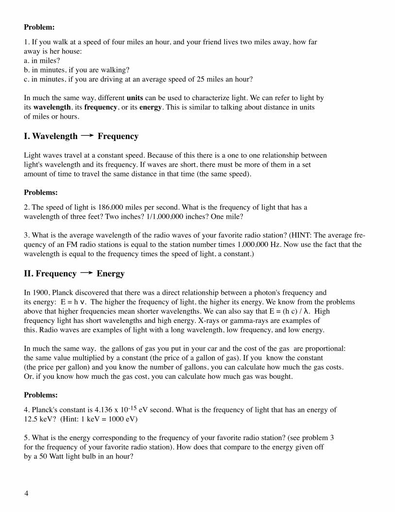
In order to measure the energy of a photon, we first need to be able to detect it. If an X-ray passes through a detector unstopped, it might as well not have been there. The solution is to direct an X-ray coming into our detector to where it can interact with an electron. One way this is done is by filling a detector with a gas like xenon. When an incoming X-ray hits the xenon gas, it will transfer its energy to a xenon atom, causing an electron to be knocked off. Because of the strong electric field set up in the detector, the electron accelerates, causing it to knock the outer electron out of another xenon atom. This continues to happen until this cascade creates a small cloud of electrons. This cloud cascades onto one of the wires in the detector, which causes an electrical charge on it. The size of the electrical charge is proportional to the energy of the initial photon. So, this method helps us not only to detect X-rays but measure their energies as well!
There are several kinds of detectors that work by causing incoming X-rays to interact with a gas, among them proportional counters. Detectors like scintillators and phosphors actually measure the visible light pro-duced when the X-rays interact with and are absorbed by the atoms contained in the gas-filled detector. Mea-suring the amount of light gives you an idea of how energetic the incoming X-ray was. Another kind of detec-tor, called a “calorimeter”, directly measures the heat produced in a cooled gas when an incoming X-ray is absorbed by it.
One obstacle to X-ray observations is the interference of the X-ray background. In addition to X-rays coming from the source you are pointing at (and want to measure), there are photons and high-energy particles hitting your telescope and detector from other sources and from all angles. These can be solar X-rays reflected from the atmosphere, or high-energy particles from the Sun that are reacting with your detector and pretending they're X-rays. All this extraneous stuff is known as noise. A reasonable analogy of the "source" versus "noise" problem can be found in the school cafeteria at lunchtime. Usually, there is a hubbub of noise and con-versation, and it's hard to hear what everyone is saying. Imagine trying to pick up the one conversation you want to hear among all of the other conversations going on around you. Being able to isolate and detect X-ray signals from a source over the background noise is a subtle art that is very important.
X-ray detectors are just one part of what makes up a satellite. They are a very important part, indeed they are the reason for having X-ray satellites. But we can’t just stick an X-ray detector on a rocket and blast it off and expect it to work. Satellites need power and electricity, not only to run the instruments, but to move the satel-lite itself around. When we use a small telescope on the ground, we can swivel it around to the area of the sky we are interested in looking at. Because we can’t do that to a satellite, we have to send it commands to
11

rotate, so it can point its instruments in the direction we want them to see. In order to send commands up to the satellite, we need some sort of radio communications device. There is a lot that goes into designing a sat-ellite, such as making sure it doesn’t vibrate so much that the instruments get jittered around. The instruments have to be insulated from extreme heat and cold and designed to withstand the low pressure, zero gravity envi-ronment of space.
Here we summarize the basic parts of a satellite and their functions.
Power - Electricity is needed for the instruments and to allow the spacecraft directional control. Power is provided by solar arrays in most cases, or, in cases like the recently launched, Saturn-bound, satellite, Cassini , where solar arrays do not supply enough power for planetary probes, nuclear gen-erators are used.
Communication - The satellite has to communicate with ground control so directions and commands can be sent up and data sent down. To provide radio contact, satellites have radio antennas.
Guidance - Star trackers and gyroscopes help satellites align themselves in the right direction to acquire sources.
Science - Of course, satellites have scientific instruments on them!
What kind of orbits are scientific satellites put into? Usually they are put into low-Earth orbit, for example, RXTE is orbiting 570 km above us. It takes RXTE about 90 minutes to orbit the Earth once. The Hubble Space Telescope orbits at approximately 600 km and traverses the Earth once every 96 minutes.
Here is an exercise in scale. The Rossi X-ray Timing Explorer (RXTE) has dimensions of 6 feet x 6 feet x 18 feet. Try these calculations:
1. If you built a model of RXTE that was 1/3 the size of the real satellite, what dimensions would it have?
2. What fraction of the size of the real RXTE would a model with dimensions 2" x 2" x 6" be?
3. RXTE's solar panels are each 10.5' x 27.5'. If you wanted to build a model solar panel that was 1/6 the size of a real one, what would its dimensions be?
Try building your own model of RXTE to help you with these calculations! The pieces necessary for thefull-color model is stapled in the centerfold of this booklet. Use the instructions included at the end of this booklet to put it together. There is a black and white version of the model (perfect for coloring) at the back of the booklet that can be photocopied for classroom purposes.
12
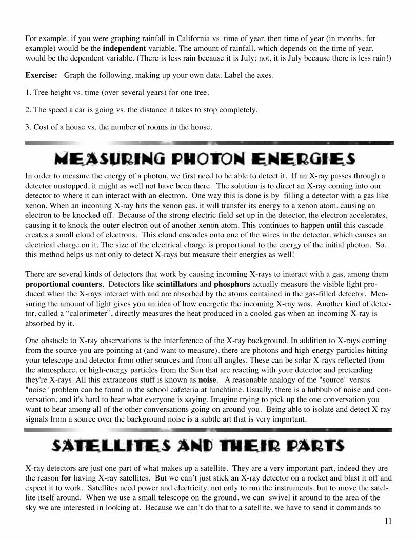
The Rossi X-ray Timing Explorer (RXTE), named after Bruno Rossi, discoverer of the first non-solar source of X-rays, was launched on December 30, 1995. Its instruments generate spectra and light curves, but not images. RXTE has three different scientific instruments on it, the Proportional Counter Array (PCA), the High Energy X-ray Timing Experiment (HEXTE), and the All-Sky Monitor (ASM). These three instruments comple-ment each other for several reasons. For example, they all observe different energy ranges.
The PCA has five xenon gas proportional counter detectors (the X-rays interact with the electrons in the xenon gas) that measure X-rays in the 2-60 keV range.
HEXTE has eight sodium-iodide crystal detectors that are gathered into two clusters, each containing 4 scin-tillation detectors that measure X-rays in the 10-200 keV range. While one cluster is pointed directly at the source, the other cluster is slightly offset, looking at blank sky. Each cluster is on a mechanism which “rocks” (by rotating on its axis) once every 32 seconds. So a given cluster points at the source for 32 seconds, then shifts to an off-source position and stays there for 32 seconds, then shifts back to the on-source position. (The other cluster is doing the opposite: off-source, on-source, off-source.) The data from one particular cluster are analyzed by subtracting the off-source position data from the on-source position data. This background sub-traction helps reduce the “noise”.
The ASM has three cameras that are mounted on a boom off the end of the spacecraft. Inside each camera is a proportional counter sensitive to energies in the 2-10 keV range. Each camera is able to look at a different region of the sky; two of the cameras have an overlapping field of view. The entire boom the cameras are mounted on rotates by 6 degrees once every 90 seconds. Through this sequence of rotating and then staying fixed for 90 seconds, etc., the ASM covers 80% of the sky in 90 minutes.
It is good that part of the energy ranges of these instruments overlap - it increases confidence in their scientific results! The ASM is a good instrument for monitoring the sky for transient, or short-lived events. The PCA and HEXTE complement the ASM by having the ability to follow up anything the ASM sees with more detailed and sensitive observations.
RXTE uses solar panels for power. The solar energy that they provide is the same as the solar energy we talk about using to make solar cars and solar houses on Earth. For communication, RXTE uses two high gain antennas and several low gain ones. For guidance, it uses star trackers.
13

The Rossi X-ray Timing Explorer (RXTE) probes the physics of cosmic X-ray sources by taking their spectra and by making sensitive measurements of their variability over time scales ranging from milliseconds to years. This time behavior is a source of important information about processes and structures in X-ray binary sys-tems, black holes, neutron stars, X-ray pulsars, and X-ray bursters.
Below is a list of a few of the types of objects that RXTE observes.
Binary star systems contain two stars orbiting around their com-mon center of mass. Many of the stars in our Galaxy are part of a binary system. A special class of binary stars is X-ray binaries, so-called because they emit X-rays. X-ray binaries are made up of a normal star and a collapsed star (a neutron star or black hole). These pairs produce X-rays if the stars are close enough together that material is pulled off the normal star by the gravity of the dense, collapsed star. The X-rays come from the area around the collapsed star where the material that is falling toward it is heated to very high temperatures (over a million degrees!).
An accretion disk is a relatively flat sheet of gas surrounding a newborn star, a black hole, pulsar or any mas-sive object growing in size by attracting material, usually from a companion star, as shown above.Matter from an accretion disk is heated as it falls onto the companion, emitting X-rays.
A black hole is a region of space from which neither radiation (light) nor matter can escape. We can most easily detect them in binary systems when we can observe the black hole pulling matter off its companion star into an orbiting disk. As the matter falls close to the event horizon, or outer limit of the black hole, it heats up, releasing X-rays.
A neutron star is the imploded core of a massive star produced by a supernova explosion. Its typical mass is 1.4 times the mass of the sun, and typical radius is about 5 miles. An X-ray Pulsar is a rotating neutron star which generates regular pulses of radiation at X-ray wavelengths by accreting matter from a companion star. It may also emit radiation pulses at other wavelengths.
An X-ray burster is an X-ray source in which there may occur very short but very powerful bursts of X-rays. They usually last no longer than 10 seconds, but pack as much energy as the sun emits in its corona in 3000 years. The bursts are due to sudden burning of hydrogen which has accumulated on the surface of the star. X-ray bursters are usually found in binary systems where the companion star has a Sun-like mass.
Sometimes stars will let out a large amount of energy, which may be visible at more than one wavelength, and then seem to disappear or become quiet. We call these objects transients because their energy outburst is not permanent, but short-lived. Some transients have outbursts which occur at regular intervals or periodically. Others may outburst unpredictably; some sources have only been observed to burst once and then never again! Transient outbursts are due to a change in rate of material falling onto a neutron star or a black hole. The rate of the infalling material can change if there is an instability in a companion star or an instability in the accre-tion disk surrounding the neutron star or black hole. A good analogy for transient events is a fireworks dis-play. Your X-ray detector may see a bright flash where there was none before, and then like a burst of fire-works, it fades away. 14

Plot these X-ray sources on the map of the Galactic Center using their coordinates. Why is the X axis labeled so strangely? It is because it shows Galactic Coordinates. Because we view the sky as being curved, when we project it onto a map, we label it much like we label a globe. The X and Y coordinates are really latitude and longitude, and measured from -90 to 90 degrees and 0 to 360 degrees respectively.
Source name Coordinates (Galactic latitude, longitude) Source Type Sco X-1 359, 23 Neutron Star GX 9+9 8.5, 9 Neutron Star X 1636-536 333, -4.8 X-ray Binary System X 1822-371 357, -11 X-ray Binary System GX 17+2 16.4, 1.3 Neutron Star Nova Sco 94 345, 2.45 Nova GX 354-0 354, -15 X-ray Burster NGC 6624 2.79, -7.9 Globular Cluster X 1735-444 346, -6.99 X-ray Burster GRO J 1744-28 0.05, 0.3 X-ray Binary System
15

RXTE has made some amazing discoveries; many times, though, its observations create more mysteries than they solve. Such is the way of science. Here are a few of the strange and wonderful things RXTE has shown us. For more details on any of these items, please see:
http://rxte.gsfc.nasa.gov/docs/xte/learning_center/rxte_discoveries.html
Quasi-Periodic Oscillations (QPOs)
The Rossi X-ray Timing Explorer (RXTE) discovered neutron stars that emit streams of X-rays that pulse over 1,000 times a second in August of 1996. The pulses are not strictly periodic (reoccurring at a constant rate), but vary slightly from cycle to cycle. Astronomers call them "quasi-periodic oscillations" or QPOs. This just means that the pulses are almost, but not quite, periodic. QPOs are significant because they can tell us about how material falls onto a neutron star or black hole and can give us information on the interaction between an accretion disk and the source it surrounds.
Black Hole Drags Space-Time
Astronomers Dr. Wei Cui of MIT, Dr. Wan Chen of NASA's Goddard Space Flight Center and Dr. Shuang N. Zhang of NASA's Marshall Space Flight Center used RXTE in November 1997 to observe a black hole that appears to be dragging space and time around itself as it rotates! A good analogy is a bowling ball immersed in molasses. When the bowling ball rotates, it drags the molasses with it, just like a black hole drags space-time. This effect is called "frame dragging" and it is something that Einstein's General Theory of Relativity predicts. This is the first time that physical evidence to support this aspect of Einstein's 1918 theory has been available.
Black Hole Sheds Accretion Disk
In January of 1998 it was discovered that every half hour or so, the black hole known as GRS 1915+105 throws off the inner portion its accretion disk, creating a jet that seems to travel at near light speeds. This disk of matter re-forms itself after each jet as the black hole pulls in more matter from its companion star. Even more amazing are the audio files of this phenomenon, located on our web site. Thanks to Dr. Ed Morgan of MIT, it is actually possible to listen to this black hole throw off the inner portion of its disk.
The Missing Link Pulsar
A newly-discovered star that is emitting rapid pulses of X-rays may be the long-sought missing link between old neutron stars that emit powerful flashes of X-rays, and older, rapidly spinning neutron stars that emit mainly radio waves. This star, designated SAX J1808.4-3658, is located 12,000 light years away towards the constellation Sagittarius. The discovery, made two competing teams of scientists using the Rossi X-ray Timing Explorer, was announced in July 1998. This new pulsar helps scientists resolve a mystery. Prior to the discov-ery, two populations of neutron stars with relatively weak magnetic fields but with otherwise different charac-teristics were known. There are old, accreting neutron stars, which generate X-rays from the material they are gobbling up from their companions, and a group of radio wave emitting millisecond pulsars that are rotating very rapidly and slowing down gradually. Scientists suspected there was a connection between the two, and the discovery of this pulsar that is both emitting X-rays and spinning rapidly provides the link. "This has sometimes been called the Holy Grail of X-ray astronomy," Dr. van der Klis, one of the scientists, exclaimed.
16

Common Unit Prefixes Used In Astronomy: -------------------------------------------------------------------
Small Large pico (p) = 10-12 kilo (k) = 103
nano (n) = 10-9 mega (M) = 106
micro (μ) = 10-6 giga (G) = 109
milli (m) = 10-3 tera (T) = 1012 centi (c) = 10-2
Energy, Frequency, and Wavelength Conversions for the Electromagnetic Spectrum
Type of Radiation Frequency Range Wavelength Range Energy Range ----------------------------------------------------------------------------------------------------------------------------
radio less than 1011 Hz longer than 2 mm below 4 x 10⁻⁴ eV microwave 3 x 10¹¹ - 109 Hz 1 mm - 30 cm 4 x 10⁻⁶ - 10 -3 eV infrared 3 x 10¹⁴ - 1012 Hz 1 - 100 μm 1.24 - 0.0124 eV optical 7.5 x 10¹⁴ - 4.2 x 10¹⁴ Hz 400 - 700 nm 1.77 - 3.102 eV ultraviolet 3 x 10¹⁷ - 7.5 x 10¹⁴ Hz 1- 400 nm 1.2 keV - 3.102 eV X-ray 1016 - 1020 Hz 3 x 10⁻⁸ m - 3 x 10-13 m 250 eV - 200 keV gamma-ray greater than 1018 Hz greater than 10-11 m above 50 keV
17

Books:
Basic Astronomy:
Chaisson, Eric and Steve McMillan. Astronomy Today . 1993, Prentice Hall, Englewood Cliffs, NJ, ISBN 0-13-050824-1. Great basic astronomy text with lots of illustrations - appropriate for high school and above.
Zeilik, Michael. Astronomy : The Evolving Universe. 1997, John Wiley & Sons, ISBN: 0-471-13566-6. Writ-ten by the author of the great out-of-print book, Astronomy: The Cosmic Perspective. Lots of illustrations.
X-ray Astronomy:
Charles, Philip A. and Frederick D. Seward. Exploring the X-ray Universe. 1995, Cambridge University Press, ISBN 0-521-43712-1. Slightly advanced, wonderful overview of X-ray astronomy - gives historic perspective.
Aschenbach, Bernd, Hahn Hermann-Michael, and Joachim Trumper. The Invisible Sky: ROSAT and the Age of X-ray Astronomy. 1998, Springer-Verlag, New York, NY, ISBN 0-387-94928-3. Has a great section on multi-wavelength astronomy, the history of X-ray astronomy, and many beautiful color images from ROSAT.
Magazine Articles:
Bartusiak, Marcia. “X-rays Expose a Violent Sky”, Smithsonian, July 1998, vol. 29, no. 4. Discusses the soon-to-be launched X-ray satellite AXAF and how it detects X-rays.
Winn, Joshua N. “An X-rated View of the Sky”, Mercury, Jan./Feb. 1998, vol. 27, no. 1. Wonderful descrip-tion of what the X-ray sky looks like from Earth, and what X-rays can tell us about the Universe. Also dis-cusses upcoming X-ray astronomy missions.
Web Sites:
General Astronomy:
Imagine the Universe! - http://imagine.gsfc.nasa.gov Introduction to the structure and evolution of the Universe, includes many resources/lesson plans for teachers. Intended age group is high school and college.
StarChild - http://starchild.gsfc.nasa.govA learning center for young astronomers - information and activities designed for grades K-8.
The Electromagnetic Spectrum:
Electromagnetic Spectrum - http://www.uccs.edu/~danderso/spectrum.htmWonderfully illustrated!18
ReSOURCES

Imagine the Universe! - The Electromagnetic Spectrum -http://imagine.gsfc.nasa.gov/docs/introduction/emspectrum.html
Electromagnetic Spectrum - All About Spectra -http://www.ncsa.uiuc.edu/Cyberia/Bima/spectrum.html
Electromagnetic Spectrum Activities - http://www.athena.ivv.nasa.gov/curric/space/lfs/emspectr.html
Lesson Plan on the Electromagnetic Spectrum - “What’s the Frequency, Roy G. Biv?” -http://imagine.gsfc.nasa.gov/docs/teachers/lessons/roygbiv/roygbiv_cover.html
Lesson Plan on “Vibration, Electronic Signals and the Electromagnetic Spectrum” -http://cse.ssl.berkeley.edu/lessons/indiv/regan/summary.html
Lesson Plan on “The Electromagnetic Spectrum On Trial” -http://cse.ssl.berkeley.edu/lessons/indiv/nellie/new_nelli_summary.html
Multiwavelength Astronomy:
Imagine the Universe - Multiwavelength Astronomy - http://imagine.gsfc.nasa.gov/docs/introduction/multiwavelength.html
Multiwavelength Atlas of Galaxies - http://www.aao.gov.au/local/www/mackie/atlas/atlas_edu.html Multiwavelength Milkyway - http://adc.gsfc.nasa.gov/mw/milkyway.html
X-ray Astronomy:
Imagine the Universe! - Light Curves, Spectra, and Images - http://imagine.gsfc.nasa.gov/docs/introduction/analysis.html
Imagine the Universe! - X-ray Astronomy -http://imagine.gsfc.nasa.gov/docs/introduction/xray_information.html
Imagine the Universe! - X-ray Generation -http://imagine.gsfc.nasa.gov/docs/introduction/xray_generation.html
Imagine the Universe! - Spectral Analysis -http://imagine.gsfc.nasa.gov/docs/introduction/spectral.html
Imagine the Universe! - Timing Analysis -http://imagine.gsfc.nasa.gov/docs/introduction/timing.html
Imagine the Universe! - X-ray Telescopes -http://imagine.gsfc.nasa.gov/docs/introduction/xray_telescopes.html
Imagine the Universe! - X-ray Detectors -http://imagine.gsfc.nasa.gov/docs/introduction/xray_detectors.html
19
20
1. The image of the IR man is from the Infrared Processing and Analysis Center at the California Institute of Technology. A color image is available on the web at http://www.unidata.ucar.edu/staff/blynds/ir_man.html
2. The spectacular color image of NGC 2300 is available at http://oposite.stsci.edu/pubinfo/jpeg/ngc2300.jpg
3. The Radio survey, courtesy of The Max Planck Institute for Radio Astronomy and generated by Glyn Haslam, is a mosaic of data taken at Jodrell Bank, Effelsberg and Parkes telescopes. The datawas distributed in the "NRAO Images from the Radio Sky" CD ROM. This image was generated by SkyView.Energy= 1.69x10⁻⁶ eV Frequency= 408x106 Hz (408 MHz) Wavelength= 73.5 cm. For a larger, color image, see http://antwrp.gsfc.nasa.gov/htmltest/jbonnell/www/multiw_sky.html
4. The Infrared image of the Milkyway Way was taken by the Infrared Astronomical Satellite (IRAS) and is courtesy of IPAC. For a full color image, see http://www.ipac.caltech.edu/Outreach/Gallery/IRAS/allsky.jpg
5. The Optical all-sky panoramic image of the Milky Way galaxy was created under the direction of Knut Lun-dmark at Lund Observatory in the 1940s. Energy= 2.5 eV Frequency= 6.0x10 14 Hz Wavelength= 5.0x10⁻⁵ cm (5000 Angstroms) Lund Observatory. For more information, and a higher resolution image, see http://www.astro.lu.se/milkyway.html
6. The X-ray image was taken by the German Roentgen Satellite (ROSAT) and is courtesy of S. Snowden and the Max Planck Institute. For a color image, see http://heasarc/Images/rosat/misc_threequarter_allsky.html
7. The gamma-ray map was generated by the EGRET (Energetic Gamma-Ray Experiment Telescope) team at Goddard using EGRET data from the first year of Compton Gamma-Ray Observatory (CGRO) operations (beginning April 1991). It represents the first all-sky survey at energies above 100keV. Energy > 100MeV Frequency > 2.5x10²² Hz Wavelength < 1.2 x 10⁻¹² cm
8. Radio image courtesy of the National Radio Astronomy Observatory. Color image available athttp://imagine.gsfc.nasa.gov/docs/science/know_l2/multiwavelength.html
9. Optical image of the crab nebula courtesy of the Anglo-Australian Observatory. Color image available athttp://imagine.gsfc.nasa.gov/docs/science/know_l2/multiwavelength.html
10. The Ultraviolet image is from the Ultraviolet Imaging Telescope. Color image available athttp://imagine.gsfc.nasa.gov/docs/science/know_l2/multiwavelength.html
11. The X-ray image is from the Roentgen Satellite (ROSAT). Color image is available at http://imagine.gsfc.nasa.gov/docs/science/know_l2/multiwavelength.html
12. The image of SN 1006 was taken by ASCA. A color image is available athttp://heasarc.gsfc.nasa.gov/Images/asca/sn1006.html

BUILD YOUR OWN MODEL OF RXTE!What you will need:
Scissors or Exacto knifeTapeWood Pencil (to be used in construction of solar panels)StaplerOne Hole Punch (optional)The two color plates of the model, which are stapled into the centerfold of this booklet(There are black &white copies of the model at the back of the booklet for photocopying purposes.)
What your model will look like:
21

Instructions:
1. Cut entire body out. (Be sure you don’t inadvertently cut any tabs off.)
2. Cut out the two grey circles located on the body. This is easiest when done with an Exacto knife or a single hole punch, but scissors can also be used. The diagram to the right shows where on the body the two grey circles are located.
3. Slice the bold line where Tab A connects to the body. The diagram below illustrates.
4. Make a slit by slicing the line on Side Panel 1 and the slits locat-ed both on Side Panel 2 and the body. The diagram to the right shows arrows pointing to the lines you should slit.
5. Cut the ASM Piece out and fold along Tab B (located at the far left in this drawing).
22

6. Insert Tab B into the slit in Side Panel 1. Tape it in place on the back as shown below.
7. Cut out the two High Gain Antennae (A and B). Cut along the solid black lines at each end. Fold along the dotted lines to form a long triangular tube. Use small tab to aid in tape the ends of the tube together. Fold back the flaps at each end.
8. Take High Gain Antenna A (the longer of the two) and insert the petals into the slits cut on Side Panel 2. Tape them in place on the back. High Gain Antenna B should be attached in the same manner to the slits that were cut on the body.
9. Fold all other tabs on the body. There are two on Side Panel 1, one on the Top Panel, and two on Side Panel 2. Fold the major body panels along the solid black lines. Do not fold the Side Panels themselves yet.
10. Fold the body into a box-like structure. Tab A will end up inside the box. Insert Tab C into the line that was sliced in Step 3. Tape Tabs A and C inside the box. When one looks through the box, it should resemble the diagram to the right.
11. Fold Side Panels 1 and 2 down and tape. It may help to use a pencil or pen to smooth the tape down as you go. You will end up with a closed box.
12. Fold the ASM pieces towards each other. Fold the ASM Piece up at the neck. Fold Tab D and the three white tabs attached to it down. Tape white tab 1 to the left ASM arm, white tab 3 to the right ASM arm, and white tab 2 to the bottom ASM arm. You should end up with a small box-like structure at the end of the ASM arms. See diagrams at the top of the next page for help.
23

13. Bend High Gain Antenna A (the one attached to the Side Panel 2) up through 45 degrees at the black line through its middle. Cut out purple Squares 1 and 2. Fold them both in half along the middle black line. Tape the sides so you are left with a square that has the purple pattern on both sides. Tape a purple square to each antenna. Make sure the edges of the squares and the edges of the body of the model are parallel.
14. Cut out both solar panels. Fold both in half along the middle black line. Tape two of the open sides being sure to leave the side with the tabs open.
15. Take wooden pencil and insert one end into the open end (the side with the tabs) of one solar panel. Staple the middle of the solar panel to the pencil. Poke the free end of the pencil through the holes that were cut out in Step 2. Staple the other solar panel to the other end of the pencil, being careful to keep the solar panels aligned in the same direction.
24


Produced byNASA Goddard Space Flight Center
Laboratory for High Energy Astrophysics