An improved MPS method for numerical simulations of ... An improved MPS method for numerical...
17
INTERNATIONAL JOURNAL FOR NUMERICAL METHODS IN FLUIDS Int. J. Numer. Meth. Fluids 2006; 51:31–47 Published online 15 November 2005 in Wiley InterScience (www.interscience.wiley.com). DOI: 10.1002/d.1106 An improved MPS method for numerical simulations of convective heat transfer problems Shuai Zhang 1; ∗; † , Koji Morita 2; ‡ , Kenji Fukuda 2; § and Noriyuki Shirakawa 3; ¶ 1 Department of Applied Quantum Physics and Nuclear Engineering; Kyushu University; Fukuoka; Japan 2 Institute of Environmental Systems; Kyushu University; Fukuoka; Japan 3 Nuclear Power Engineering Corporation; Tokyo; Japan SUMMARY An improved moving-particle semi-implicit (MPS) method was developed for numerical simulations of convective heat transfer problems. The MPS method, which is based on particles and their interactions, is a fully Lagrangian particle method for incompressible ows. A new Laplacian model and a new method for treating boundary conditions were proposed to solve numerical diculties resulting from the original MPS method. Results of several numerical tests show the validity of the improved MPS method with the proposed model and method. The application of the present MPS method to Rayleigh–Benard convection phenomena demonstrated the eectiveness of the proposed model and method on the numerical simulation of convective heat transfer problems. The dependence of the Nusselt number on the Rayleigh number was in good agree- ment with an empirical formula. The temperature contour and velocity distribution also agree well with the simulation results obtained with other methods. The roll pattern developed in the horizontal uid layer as well as the convective heat transfer was successfully simulated with three-dimensional MPS calculations. Copyright ? 2005 John Wiley & Sons, Ltd. KEY WORDS: moving-particle semi-implicit (MPS) method; convective heat transfer; Laplacian model; Rayleigh–Benard convection 1. INTRODUCTION It is dicult for Eulerian methods to analyse complex geometries and to treat viscous uid ows without numerical diusion caused by uid convection. Lagrangian methods are other ∗ Correspondence to: Shuai Zhang, Department of Applied Quantum Physics and Nuclear Engineering, Kyushu University, Fukuoka, Japan. † E-mail: [email protected] ‡ E-mail: [email protected] § E-mail: [email protected] ¶ E-mail: [email protected] Contract=grant sponsor: Ministry of Education, Culture, Sports, Science and Technology, Japan Received 26 April 2005 Revised 16 August 2005 Copyright ? 2005 John Wiley & Sons, Ltd. Accepted 23 August 2005
Transcript of An improved MPS method for numerical simulations of ... An improved MPS method for numerical...

INTERNATIONAL JOURNAL FOR NUMERICAL METHODS IN FLUIDSInt. J. Numer. Meth. Fluids 2006; 51:31–47Published online 15 November 2005 in Wiley InterScience (www.interscience.wiley.com). DOI: 10.1002/�d.1106
An improved MPS method for numerical simulations ofconvective heat transfer problems
Shuai Zhang1;∗;†, Koji Morita2;‡, Kenji Fukuda2;§ and Noriyuki Shirakawa3;¶
1Department of Applied Quantum Physics and Nuclear Engineering; Kyushu University; Fukuoka; Japan2Institute of Environmental Systems; Kyushu University; Fukuoka; Japan
3Nuclear Power Engineering Corporation; Tokyo; Japan
SUMMARY
An improved moving-particle semi-implicit (MPS) method was developed for numerical simulations ofconvective heat transfer problems. The MPS method, which is based on particles and their interactions,is a fully Lagrangian particle method for incompressible �ows. A new Laplacian model and a newmethod for treating boundary conditions were proposed to solve numerical di�culties resulting fromthe original MPS method. Results of several numerical tests show the validity of the improved MPSmethod with the proposed model and method.The application of the present MPS method to Rayleigh–Benard convection phenomena demonstrated
the e�ectiveness of the proposed model and method on the numerical simulation of convective heattransfer problems. The dependence of the Nusselt number on the Rayleigh number was in good agree-ment with an empirical formula. The temperature contour and velocity distribution also agree well withthe simulation results obtained with other methods. The roll pattern developed in the horizontal �uidlayer as well as the convective heat transfer was successfully simulated with three-dimensional MPScalculations. Copyright ? 2005 John Wiley & Sons, Ltd.
KEY WORDS: moving-particle semi-implicit (MPS) method; convective heat transfer; Laplacian model;Rayleigh–Benard convection
1. INTRODUCTION
It is di�cult for Eulerian methods to analyse complex geometries and to treat viscous �uid�ows without numerical di�usion caused by �uid convection. Lagrangian methods are other
∗Correspondence to: Shuai Zhang, Department of Applied Quantum Physics and Nuclear Engineering, KyushuUniversity, Fukuoka, Japan.
†E-mail: [email protected]‡E-mail: [email protected]§E-mail: [email protected]¶E-mail: [email protected]
Contract=grant sponsor: Ministry of Education, Culture, Sports, Science and Technology, Japan
Received 26 April 2005Revised 16 August 2005
Copyright ? 2005 John Wiley & Sons, Ltd. Accepted 23 August 2005

32 S. ZHANG ET AL.
approaches to overcome these problems. A moving-particle semi-implicit (MPS) method [1]is a deterministic Lagrangian method developed for simulating incompressible �uids. In thismethod, governing equations are discretized based on particle interaction models representinggradient, Laplacian and free surface. Computational grids are unnecessary. Based on the MPSmethod, a combined grid and particle method, MPS-MAFL [2], which can easily solve �owproblems with inlets and outlets, has been formulated. A two-�uid MPS method [3] has beendeveloped extensively for two-phase �uid problems. All these methods have been applied withsatisfying results in natural and engineering �elds.However, the original Laplacian model [1] presented in the MPS method would overestimate
heat transfer when applied to an energy equation. We also found that it was di�cult for theMPS method to obtain numerical stability for natural convection �ows with a low Reynoldsnumber or in an enclosure. In addition, the cut-o� radius de�ned in the gradient or theLaplacian models cannot satisfy geometric boundaries because wall boundaries are simulatedby one-layer particles with zero velocities. To overcome these problems, in the present paper,we will propose a new Laplacian model for the heat transfer along with a new treatment forthermal and non-slip boundaries.Rayleigh–Benard convection takes place in a horizontal layer, which is heated from the bot-
tom and cooled from the top. A stable conduction exists for this problem when the temperaturedi�erence between the bottom and top boundaries is small enough. When a temperature dif-ference is increased above a certain threshold, the static conduction becomes unstable againstany small disturbance, and the system then becomes unstable. Chandrasekhar presented a lucidintroduction and thorough coverage of the theory to this phenomenon [4]; and there have beensome reviews on experiments and numerical calculations in this particular �eld [5]. Recently,new technologies have been applied to the study of the role of molecules in macroscopic�ow phenomena, for example the molecular dynamics [6], the direct simulation Monte Carlo[7] and the lattice Boltzmann method [8]. Most of these simulations were done in the Eulerframework. Smoothed particle applied mechanics, a grid-free Lagrangian method, was used tosimulate the Rayleigh–Benard convection to emphasize and discuss the connection betweenmolecular dynamics and continuum mechanics [9]. In this contribution, the MPS method witha new Laplacian model and a new method for treating the boundary conditions will be usedto simulate Rayleigh–Benard convection with a range of Rayleigh number.
2. NUMERICAL MODELS AND METHODS FOR MPS
2.1. Governing equations in MPS method
Governing equations for incompressible �ows are mass, momentum and energy conservationequations given as follows:
@�@t+∇ · (�u) = 0 (1)
DuDt
= −∇p�+ �∇2u+ F (2)
�cpDTDt
= �∇2T − q (3)
Copyright ? 2005 John Wiley & Sons, Ltd. Int. J. Numer. Meth. Fluids 2006; 51:31–47

IMPROVED MPS METHOD 33
2.1.1. Kernel function. In MPS, the kernel function w(|rj − ri|; re) is chosen as [1]
w(|rj − ri|; re) =
⎧⎪⎪⎨⎪⎪⎩
re(|rj − ri|) − 1 (|rj − ri|¡re)
0 (|rj − ri|¿re)(4)
n0 =∑j �=iw(|rj − ri|; re) (5)
where re is the cut-o� radius. In the present MPS method, it is chosen to be 2:1�l, where�l is the initial distance between two particles. With this kernel function, particle clusterscan be avoided since the value of kernel function is in�nity at |rj − ri|=0.
2.1.2. Gradient model. Assuming two particles i and j, which possess scalar quantities �i and�j, respectively, the gradient in the MPS method is de�ned as [1]
〈∇�〉i= dn0
∑j �=i
�j −�i|rj − ri|2 (rj − ri)w(| rj − ri|; re) (6)
where d is the number of the space dimension.Equation (6) can be rearranged as follows:
〈∇�〉i= dn0
∑j �=i
�j −�′i
|rj − ri|2 (rj − ri)w(|rj − ri|; re) (7)
where �′i = min(�j). Equation (7) is tested to be able to improve numerical stability [1].
2.1.3. Laplacian model. The original Laplacian model in the MPS method is given byKoshizuka and Oka [1]
〈∇2�〉i= 2dn0�
∑j �=i(�j −�i)w(|rj − ri|; re) (8)
where
�=∫w(|rj − ri|; re)|rj − ri|2 dv∫
w(|rj − ri|; re) dv (9)
In two dimensions, parameter � should be
�=2�
∫ ∞0 w(|rj − ri|; re)|rj − ri|3 d|rj − ri|
2�∫ ∞0 w(|rj − ri|; re)|rj − ri|d|rj − ri|
≈∫ reR w(|rj − ri|; re)|rj − ri|3 d|rj − ri|∫ reR w(|rj − ri|; re)|rj − ri|d|rj − ri|
(10)
Copyright ? 2005 John Wiley & Sons, Ltd. Int. J. Numer. Meth. Fluids 2006; 51:31–47

34 S. ZHANG ET AL.
where
R=�l=√� (11)
However, it is found that this model would overestimate heat conduction when applied toan energy equation. This will be demonstrated using the numerical test for heat conductionin a homogenous square slab in Section 3.As we know, the Laplacian model can be derived from the divergence of gradient as
〈∇2�〉i= 〈∇ · ∇(�)ij〉i (12)
where the divergence model in the MPS method is
〈∇ · �〉i= dn0
∑j �=i
(�j − �i) · (rj − ri)|rj − ri|2 w(|rj − ri|; re) (13)
Combining the gradient model and the divergence model, we can obtain the new Laplacianmodel:
〈∇2�〉i= 2dn0∑i �=j
�j −�i|rj − ri|2w(|rj − ri|; re) (14)
In the original Laplacian model, it is necessary to use a parameter, �, which is derived withthe central limit theorem. However, mathematical inconsistency in the de�nition of � couldcause numerical di�culties in calculating the Poisson equation. In contrast, Equation (14)enables us to solve the Poisson equation exactly.
2.1.4. Incompressible model. In the MPS method, each particle possesses the same mass.Therefore, every particle number density n∗ should be constant and equal to n0. Otherwise,we de�ne
n∗ + n′= n0 (15)
where n′ is the correction to the particle number density. The following can be derived:
1�t
n′
n0= −∇ · u′ (16)
u′ = −�t�
∇pn+1 (17)
where u′ is the velocity correction value and n+ 1 means the next time step number. As aresult, we get the following pressure Poisson equation [1]:
〈∇2pn+1〉i= − ��t2
〈n∗〉i − n0n0
(18)
To improve calculation stability, especially for �ows in an enclosure, the equation is modi�edas [10]
〈∇2pn+1〉i= �1 ��t ∇ · 〈u∗〉 − �2 ��t2〈n∗〉i − n0
n0(19)
Copyright ? 2005 John Wiley & Sons, Ltd. Int. J. Numer. Meth. Fluids 2006; 51:31–47
IMPROVED MPS METHOD 35
with
�1 + �2 = 1 (20)
where the parameters �1 and �2 are chosen as 0.8 and 0.2, respectively, in the present calcu-lations. u∗ is the temporal velocity.Equation (19) can be solved by the incomplete Cholesky conjugate gradient (ICCG) method,
which is robust and fast for calculations with a large number of particles.
2.2. Time integration
The MPS method separates calculations into two stages, explicit and implicit stages, in eachtime step. In the explicit stage, particles move with the viscosity and external forces that areexplicitly calculated by
u∗i = u
ni +�t(�∇2uni + Fi) (21)
r∗i = rni +�tu
∗i (22)
In the implicit stage, velocity is corrected with Equation (17) to keep the conservation ofthe momentum equation. Pressure is obtained with Equation (19) using the ICCG method.Time step is controlled in the computation to satisfy the following Courant condition:
�t 6 0:2�lumax
(23)
where �l is the initial distance between two particles, and umax is the maximal velocity amongall particles.
2.3. Boundary conditions
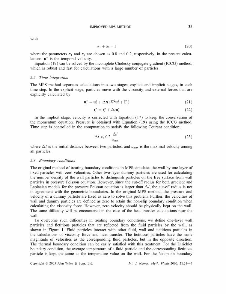
The original method of treating boundary conditions in MPS simulates the wall by one-layer of�xed particles with zero velocities. Other two-layer dummy particles are used for calculatingthe number density of the wall particles to distinguish particles on the free surface from wallparticles in pressure Poisson equation. However, since the cut-o� radius for both gradient andLaplacian models for the pressure Poisson equation is larger than �l, the cut-o� radius is notin agreement with the geometric boundaries. In the original MPS method, the pressure andvelocity of a dummy particle are �xed as zero to solve this problem. Further, the velocities ofwall and dummy particles are de�ned as zero to retain the non-slip boundary condition whencalculating the viscosity force. However, zero velocity should be physically kept on the wall.The same di�culty will be encountered in the case of the heat transfer calculations near thewall.To overcome such di�culties in treating boundary conditions, we de�ne one-layer wall
particles and �ctitious particles that are re�ected from the �uid particles by the wall, asshown in Figure 1. Fluid particles interact with other �uid, wall and �ctitious particles inthe calculations of viscosity force and heat transfer. The �ctitious particles have the samemagnitude of velocities as the corresponding �uid particles, but in the opposite direction.The thermal boundary condition can be easily satis�ed with this treatment. For the Dirichletboundary condition, the average temperature of a �uid particle and the corresponding �ctitiousparticle is kept the same as the temperature value on the wall. For the Neumann boundary
Copyright ? 2005 John Wiley & Sons, Ltd. Int. J. Numer. Meth. Fluids 2006; 51:31–47
36 S. ZHANG ET AL.
Figure 1. Numerical treatment of thermal and velocity boundary conditions.
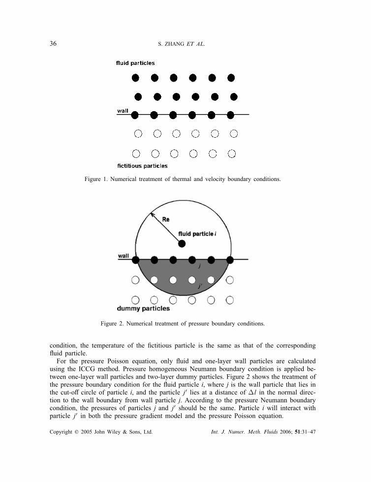
Figure 2. Numerical treatment of pressure boundary conditions.
condition, the temperature of the �ctitious particle is the same as that of the corresponding�uid particle.For the pressure Poisson equation, only �uid and one-layer wall particles are calculated
using the ICCG method. Pressure homogeneous Neumann boundary condition is applied be-tween one-layer wall particles and two-layer dummy particles. Figure 2 shows the treatment ofthe pressure boundary condition for the �uid particle i, where j is the wall particle that lies inthe cut-o� circle of particle i, and the particle j′ lies at a distance of �l in the normal direc-tion to the wall boundary from wall particle j. According to the pressure Neumann boundarycondition, the pressures of particles j and j′ should be the same. Particle i will interact withparticle j′ in both the pressure gradient model and the pressure Poisson equation.
Copyright ? 2005 John Wiley & Sons, Ltd. Int. J. Numer. Meth. Fluids 2006; 51:31–47

IMPROVED MPS METHOD 37
3. NUMERICAL TESTS FOR IMPROVED MPS METHOD
Three numerical tests were performed to demonstrate the e�ectiveness of our improved MPSmethod described above. In this section, the results of numerical tests were presented incomparison with exact analytical solutions.
3.1. Heat conduction in a square slab
Heat conduction in a homogeneous square slab was simulated with an initial sinusoidal tem-perature distribution. The top and bottom edges and lateral sides were assumed to be adiabaticand isothermal, respectively. For this problem, the exact solution is given by Cleary [11]
T (x; y; t)= sin(�xl
)exp
[−
(�l
)2�t
](24)
where l is the length of the slab and � is the thermal di�usivity. In the present simulation,the slab was modelled by a particle array of 40× 40 with l=0:1 m and �=0:1 m2 s−1. Theresults are shown in Figures 3(a) and (b) in comparison with ones obtained using the originalLaplacian model. As is seen from the �gures, the original Laplacian model overestimates theheat transfer; however, using the new Laplacian model, the simulation results agree well withthe analytical solutions, and the errors in temperature are less than 1% in the simulation.
3.2. One-dimensional heat penetration
A one-dimensional heat penetration into a semi-in�nite medium [12] was also calculated.The medium was represented by a particle array of 1000 × 20 with a thermal di�usivityof 18:7 × 10⁻⁶ m2 s−1. The initial temperatures of the wall and medium were 0 and 20◦C,respectively. Figure 4 shows the simulation result compared with the exact solutions at 5 s.
1
0.9
0.8
0.7
0.6
0.5
0.4
0.3
0.2
0.1
00
(a) (b)
0.25 0.5
Tem
pera
ture
(°C
)
Tem
pera
ture
(°C
)
Temperature profile 0.5 s. Temperature profile 1.0 s.
0.75 1 0 0.25 0.5 0.75 1
0.5
0.4
0.3
0.2
0.1
analysispresent modeloriginal model
analysispresent modeloriginal model
0
Figure 3. Comparison of temperature for heat conduction in a homogeneous square slab.
Copyright ? 2005 John Wiley & Sons, Ltd. Int. J. Numer. Meth. Fluids 2006; 51:31–47

38 S. ZHANG ET AL.
Tem
pera
ture
(°C
)
analysispresent model
0
0
5
10
15
20
0.05X (m)
0.1
Figure 4. Comparison of temperature pro�le at 5 s in one-dimensional heat penetration.
analysispresent model
0 1 2U (m/s)
y (m
)
30
0.2
0.4
0.6
0.8
1
Figure 5. Time-dependent velocity pro�le in Poiseuille �ow in a parallel plate channel.
As can be seen, there is good agreement between them. This is an accuracy typically seenthroughout the simulation.
3.3. Poiseuille �ow in a parallel plate channel
A simulation was performed for a Poiseuille �ow in a parallel plate channel at a low Reynoldsnumber. A periodic boundary condition was assumed at the channel inlet and exit, while thewall boundaries were set to be non-slip. The series solution for the time-dependent behaviour
Copyright ? 2005 John Wiley & Sons, Ltd. Int. J. Numer. Meth. Fluids 2006; 51:31–47
IMPROVED MPS METHOD 39
of this Poiseuille �ow is expressed by Morris et al. [13]
uy(x; t)=F2�y(y − l) +
∞∑n=0
4Fl2
��3(2n+ 1)3sin
(�xl(2n+ 1)
)exp
(− (2n+ 1)
2��2
l2t)
(25)
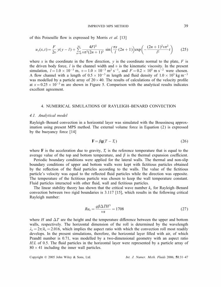
where x is the coordinate in the �ow direction, y is the coordinate normal to the plate, F isthe driven body force, l is the channel width and � is the kinematic viscosity. In the presentsimulation, l=1:0 × 10−3 m, �=1:0 × 10−3 m2 s−1, and F =0:2 × 10⁵ m s−2 were chosen.A �ow channel with a length of 0:5 × 10⁻³ m length and �uid density of 1:0 × 103 kg m−3
was modelled by a particle array of 20×40. The results of calculations of the velocity pro�leat x=0:25× 10−3 m are shown in Figure 5. Comparison with the analytical results indicatesexcellent agreement.
4. NUMERICAL SIMULATIONS OF RAYLEIGH–BENARD CONVECTION
4.1. Analytical model
Rayleigh–Benard convection in a horizontal layer was simulated with the Boussinesq approx-imation using present MPS method. The external volume force in Equation (2) is expressedby the buoyancy force [14]
F=�g(T − Tr) (26)
where F is the acceleration due to gravity, Tr is the reference temperature that is equal to theaverage value of the top and bottom temperature, and � is the thermal expansion coe�cient.Periodic boundary conditions were applied for the lateral walls. The thermal and non-slip
boundary conditions of upper and bottom walls were kept with �ctitious particles obtainedby the re�ection of the �uid particles according to the walls. The value of the �ctitiousparticle’s velocity was equal to the re�ected �uid particles while the direction was opposite.The temperature of the �ctitious particle was chosen to keep the wall temperature constant.Fluid particles interacted with other �uid, wall and �ctitious particles.The linear stability theory has shown that the critical wave number kc for Rayleigh–Benard
convection between two rigid boundaries is 3.117 [15], which results in the following criticalRayleigh number:
Rac =g��TH 3
��=1708 (27)
where H and �T are the height and the temperature di�erence between the upper and bottomwalls, respectively. The horizontal dimension of the roll is determined by the wavelength�c = 2�=kc = 2:016, which implies the aspect ratio with which the convection roll most readilydevelops. In the present simulations, therefore, the horizontal layer �lled with air, of whichPrandtl number is 0.71, was modelled by a two-dimensional geometry with an aspect ratioH=L of 0.5. The �uid particles in the horizontal layer were represented by a particle array of80× 41 including the inner wall particles.
Copyright ? 2005 John Wiley & Sons, Ltd. Int. J. Numer. Meth. Fluids 2006; 51:31–47

40 S. ZHANG ET AL.
A stable conduction exists for this problem when the temperature di�erence between thebottom and top boundaries is small enough. However, when the temperature di�erence isincreased above a certain threshold, the static conduction becomes unstable against any smalldisturbance, and the system then becomes unstable. Calculations started from a static stateexcept for the pressure �eld, which was perturbed as
p(x; y)=[1 +
��g�Ty2
(1− y
H
)][1 + 0:001 cos
(2�xL
)](28)
4.2. Calculation of results and analysis
Cell patterns, the critical Rayleigh number and heat �ux appear the most interesting aspectsof research regarding Rayleigh–Benard convection. Present simulations showed the roll pat-tern; according to linear theory, the width of rolls should be equal to the wavelength ofthe disturbance [6]. This means that there should be two cells developed in two-dimensionalsimulations, and the present simulations showed two cells developed after the �uids weresteady.The enhancement of the heat transfer can be described by the Nusselt number:
Nu=1+〈uyT 〉��T=H
(29)
where uy is vertical velocity, � is thermal di�usivity and 〈·〉 the average over the whole �owdomain. Figure 6 shows heat transfer transient from conduction to convection as the Rayleighnumber increases. When the Rayleigh number is less than 2000, the averaged Nusselt numberis almost equal to 1.0, which means that heat conduction is dominant at this stage. Whenthe Rayleigh number is larger than 2000, the averaged Nusselt number increases rapidly.Mainly, heat transfer changes from conduction to convection. Figure 7 shows the velocity
2.5
2
1.5
1
0.51000 2000 3000
Rayleigh number
Nus
selt
num
ber
4000 5000
Figure 6. Heat transfer near critical Rayleigh number.
Copyright ? 2005 John Wiley & Sons, Ltd. Int. J. Numer. Meth. Fluids 2006; 51:31–47
IMPROVED MPS METHOD 41
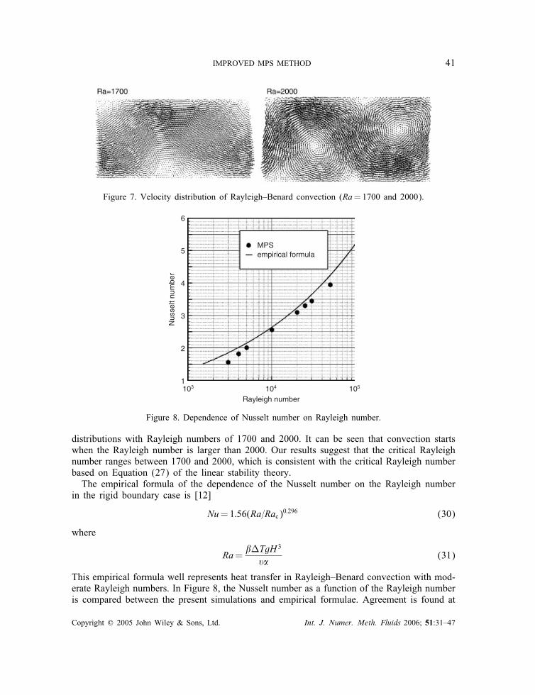
Figure 7. Velocity distribution of Rayleigh–Benard convection (Ra=1700 and 2000).
6
5MPSempirical formula
4
3
2
1103 104
Rayleigh number
Nus
selt
num
ber
105
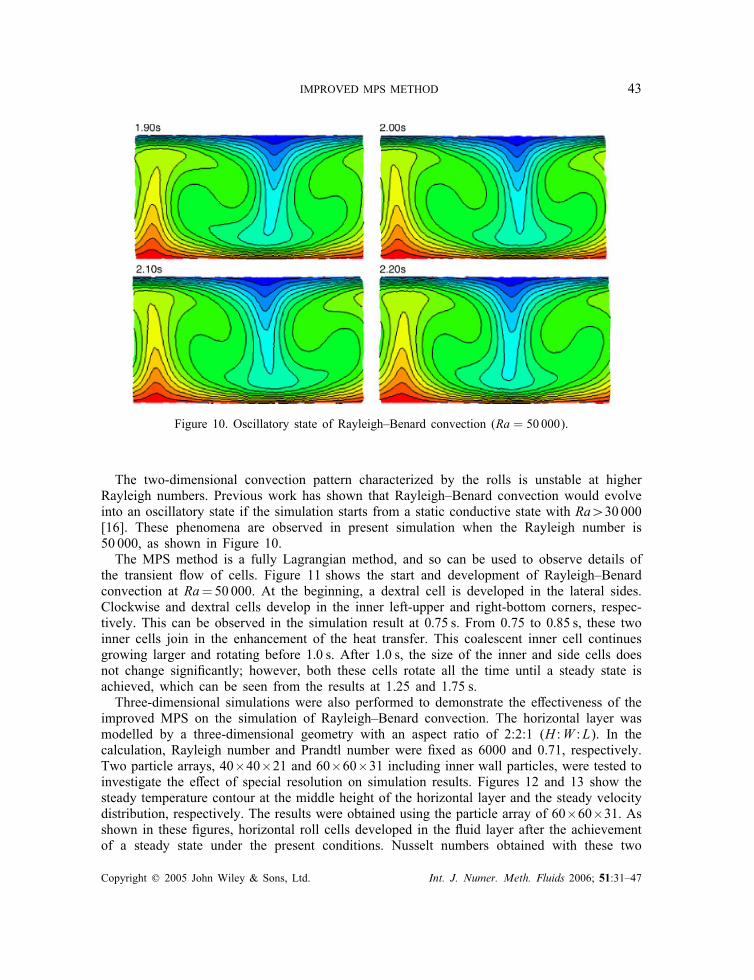
Figure 8. Dependence of Nusselt number on Rayleigh number.
distributions with Rayleigh numbers of 1700 and 2000. It can be seen that convection startswhen the Rayleigh number is larger than 2000. Our results suggest that the critical Rayleighnumber ranges between 1700 and 2000, which is consistent with the critical Rayleigh numberbased on Equation (27) of the linear stability theory.The empirical formula of the dependence of the Nusselt number on the Rayleigh number
in the rigid boundary case is [12]
Nu=1:56(Ra=Rac)0:296 (30)
where
Ra=��TgH 3
��(31)
This empirical formula well represents heat transfer in Rayleigh–Benard convection with mod-erate Rayleigh numbers. In Figure 8, the Nusselt number as a function of the Rayleigh numberis compared between the present simulations and empirical formulae. Agreement is found at
Copyright ? 2005 John Wiley & Sons, Ltd. Int. J. Numer. Meth. Fluids 2006; 51:31–47

42 S. ZHANG ET AL.
Figure 9. Velocity distribution and temperature contour of Rayleigh–Benard convection(Ra = 2500; 5000; 10 000 and 30 000).
Rayleigh numbers between 5000 and 20 000, which is consistent with the results obtainedby the lattice Boltzmann method [16]. The comparison indicates that the present MPS canreasonably predict the development of heat transfer in Rayleigh–Benard convection. Figure 9shows steady velocity distribution and temperature contours, from which it can be concludedthat the temperature gradient near the bottom and top boundaries increases as the Rayleighnumber increases.
Copyright ? 2005 John Wiley & Sons, Ltd. Int. J. Numer. Meth. Fluids 2006; 51:31–47
IMPROVED MPS METHOD 43
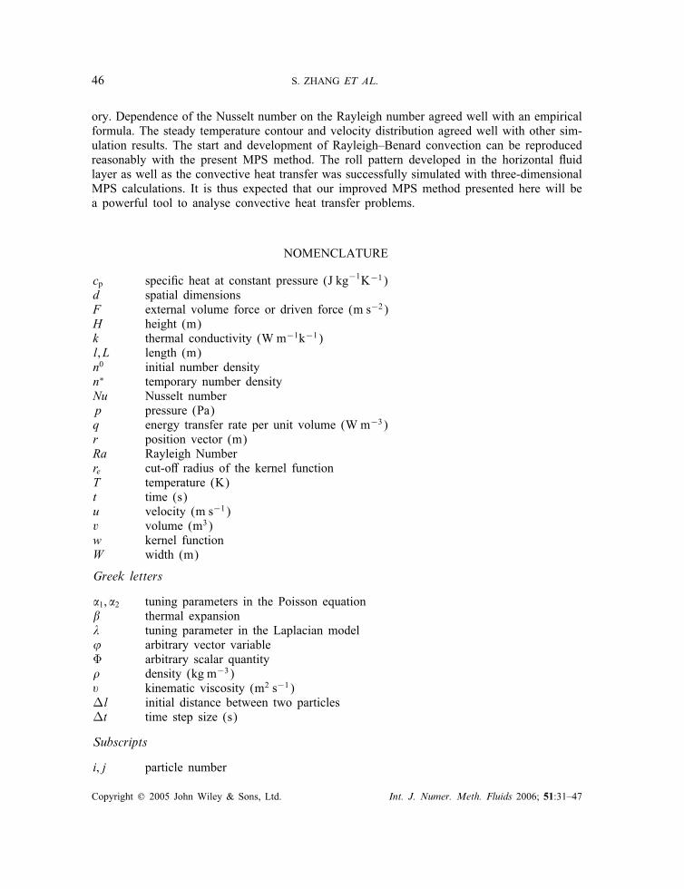
Figure 10. Oscillatory state of Rayleigh–Benard convection (Ra = 50 000).
The two-dimensional convection pattern characterized by the rolls is unstable at higherRayleigh numbers. Previous work has shown that Rayleigh–Benard convection would evolveinto an oscillatory state if the simulation starts from a static conductive state with Ra¿30 000[16]. These phenomena are observed in present simulation when the Rayleigh number is50 000, as shown in Figure 10.The MPS method is a fully Lagrangian method, and so can be used to observe details of
the transient �ow of cells. Figure 11 shows the start and development of Rayleigh–Benardconvection at Ra=50000. At the beginning, a dextral cell is developed in the lateral sides.Clockwise and dextral cells develop in the inner left-upper and right-bottom corners, respec-tively. This can be observed in the simulation result at 0:75 s. From 0.75 to 0:85 s, these twoinner cells join in the enhancement of the heat transfer. This coalescent inner cell continuesgrowing larger and rotating before 1:0 s. After 1:0 s, the size of the inner and side cells doesnot change signi�cantly; however, both these cells rotate all the time until a steady state isachieved, which can be seen from the results at 1.25 and 1:75 s.Three-dimensional simulations were also performed to demonstrate the e�ectiveness of the
improved MPS on the simulation of Rayleigh–Benard convection. The horizontal layer wasmodelled by a three-dimensional geometry with an aspect ratio of 2:2:1 (H :W :L). In thecalculation, Rayleigh number and Prandtl number were �xed as 6000 and 0.71, respectively.Two particle arrays, 40×40×21 and 60×60×31 including inner wall particles, were tested toinvestigate the e�ect of special resolution on simulation results. Figures 12 and 13 show thesteady temperature contour at the middle height of the horizontal layer and the steady velocitydistribution, respectively. The results were obtained using the particle array of 60×60×31. Asshown in these �gures, horizontal roll cells developed in the �uid layer after the achievementof a steady state under the present conditions. Nusselt numbers obtained with these two
Copyright ? 2005 John Wiley & Sons, Ltd. Int. J. Numer. Meth. Fluids 2006; 51:31–47

44 S. ZHANG ET AL.
Figure 11. Velocity distribution of Rayleigh–Benard convection at selected time intervals (Ra = 50 000).
particle-array arrangements were 2.093 and 2.151, respectively. The empirical formula yieldsNu=2:262. These mean that the error between simulations and the empirical formula woulddecrease as the number of particles used in the simulation increases. On the other hand, thereis less di�erence in the roll patterns appearing in the horizontal layer between two resultsobtained by di�erent particle-array arrangements. The simulation results on the roll patternwere in good agreement with those obtained by other numerical methods [17].
5. CONCLUSION
In this paper, we presented an improved MPS method using a new Laplacian model anda new method of treating boundary conditions for numerical simulations of convective heattransfer problems. Several numerical tests indicated the validity of the present model andmethod for the heat transfer and viscous �ow problems by comparisons with exact solutions.Rayleigh–Benard convection with di�erent Rayleigh numbers was also successfully simulated.The simulation results were consistent with those obtained by previous studies and linear the-
Copyright ? 2005 John Wiley & Sons, Ltd. Int. J. Numer. Meth. Fluids 2006; 51:31–47

IMPROVED MPS METHOD 45
Figure 12. Steady temperature contour of Rayleigh–Benard convection at the middle height of horizontalplane (Three-dimensional simulation with Ra = 6000).
Figure 13. Steady velocity distribution of Rayleigh–Benard convection(Three-dimensional simulation with Ra = 6000).
Copyright ? 2005 John Wiley & Sons, Ltd. Int. J. Numer. Meth. Fluids 2006; 51:31–47
46 S. ZHANG ET AL.
ory. Dependence of the Nusselt number on the Rayleigh number agreed well with an empiricalformula. The steady temperature contour and velocity distribution agreed well with other sim-ulation results. The start and development of Rayleigh–Benard convection can be reproducedreasonably with the present MPS method. The roll pattern developed in the horizontal �uidlayer as well as the convective heat transfer was successfully simulated with three-dimensionalMPS calculations. It is thus expected that our improved MPS method presented here will bea powerful tool to analyse convective heat transfer problems.
NOMENCLATURE
cp speci�c heat at constant pressure (J kg−1K−1)d spatial dimensionsF external volume force or driven force (m s−2)H height (m)k thermal conductivity (W m−1k−1)l; L length (m)n0 initial number densityn∗ temporary number densityNu Nusselt numberp pressure (Pa)q energy transfer rate per unit volume (W m−3)r position vector (m)Ra Rayleigh Numberre cut-o� radius of the kernel functionT temperature (K)t time (s)u velocity (m s−1)v volume (m3)w kernel functionW width (m)
Greek letters
�1; �2 tuning parameters in the Poisson equation� thermal expansion� tuning parameter in the Laplacian model’ arbitrary vector variable� arbitrary scalar quantity� density (kg m−3)� kinematic viscosity (m2 s−1)�l initial distance between two particles�t time step size (s)
Subscripts
i; j particle number
Copyright ? 2005 John Wiley & Sons, Ltd. Int. J. Numer. Meth. Fluids 2006; 51:31–47
IMPROVED MPS METHOD 47
ACKNOWLEDGEMENTS
One of the authors, Shuai Zhang, gratefully acknowledges support from the Ministry of Education,Culture, Sports, Science and Technology, Japan under the MONBUKAGAKUSHO Scholarship.
REFERENCES
1. Koshizuka S, Oka Y. Moving-particle semi-implicit method for fragmentation of incompressible �uid. NuclearScience and Engineering 1996; 123:421–434.
2. Yoon HY, Koshizuka S, Oka Y. A particle-gridless hybrid method for incompressible �ows. InternationalJournal for Numerical Methods in Fluids 1999; 30:407–424.
3. Shirakawa N, Yamamoto Y, Horie H, Tsunoyama S. Analysis of �ows around a BWR spacer by the two-�uidparticle interaction method. Journal of Nuclear Science and Technology 2002; 39(4):572–581.
4. Chandrasekhar S. Hydrodynamic and Hydromagnetic Stability. Dover: New York, 1990.5. Cross MC, Hohenberg PC. Pattern formation outside of equilibrium. Reviews of Modern Physics 1993;65:851–863.
6. Mareschal M, Kestermont E. Experimental evidence for convective rolls in �nite two-dimensional molecularmodels. Nature 1987; 329:427–429.
7. Watanabe T, Kaburaki H, Machida M, Yokokawa M. Growth of long-range in a transition between heatconduction and convection. Physical Review E 1995; 52:1601–1605.
8. He X, Chen S, Doolen GD. A novel thermal model for the lattice Boltzmann method in incompressible limit.Journal of Computational Physics 1998; 146:282–300.
9. Kum O, Hoover WG. Viscous conducting �ows with smooth-particle applied mechanics. Physical Review E1995; 52:4899–4908.
10. Ikeda H. Numerical analysis of fragmentation processes in vapor explosion using particle method. DoctoralThesis 1999, Tokyo University, Japan (in Japanese).
11. Cleary PW. Modelling con�ned multi-material heat and mass �ows using SPH. Applied Mathematical Modelling1998; 22:981–993.
12. Beek WJ, Muttzall KMK, Van Heuven JW. Transport Phenomena (2nd edn). Wiley: Chichester, 2000.13. Morris JP, Fox PJ, Zhu Y. Modeling low Reynolds number incompressible �ows using SPH. Journal of
Computational Physics 1997; 136:214–226.14. Koshizuka S, Yoon HY, Yamashita D, Oka Y. Numerical analysis of natural convection in a square cavity
using MPS-MAFL. Journal of Computational Fluid Dynamics 2000; 8(4):485–494.15. Reid WH, Harris DL. Some further results on the Benard problem. Physics of Fluids 1958; 1(2):102–110.16. Shan X. Simulation of Rayleigh–Benard convection using a lattice Boltzmann method. Physical Review E 1997;
55(3):2780–2788.17. Watanabe T. Flow pattern and heat transfer rate in Rayleigh–Benard convection. Physics of Fluids 2004;
16(4):972–978.
Copyright ? 2005 John Wiley & Sons, Ltd. Int. J. Numer. Meth. Fluids 2006; 51:31–47