
Study on the Cooling Load Caused by Envelop Heat Transfer ...

An Improved Failure Envelop for Concrete under High Strain Rate Conditions
HanGul Gang1) and *Hyo-Gyoung Kwak2)
1), 2) Department of Civil Engineering, KAIST, Daejeon 305-600, Korea
ABSTRACT An Improved Failure Envelop for concrete to describe the behavior of concrete subjected to impact loading is introduced in this paper. The introduced failure envelope is based on the dynamic failure envelope and the dynamic increase factor (DIF) obtained from multi-axial dynamic experiments for concrete. The failure envelope were compared with the available experimental data under multi-axial stresses. The results show that the introduced failure envelope can effectively be used to trace the behavior of concrete subjected to impact loading. 1. INTRODUCTION Understanding the behavior of concrete subjected to fast loadings such as impact or blast is an issue of great significance. Concrete structures subjected to blast or impact loading present significantly different structural behavior from that observed under static loading conditions. Numerous studies ranging from basic experiments to identify the dynamic material properties of concrete to blast or impact analyses of concrete structures have been conducted. Notably, Malvar and Ross (1998) summarized the test results of concrete in dynamic tensile loading, and Grote et al. (2001) generalised the dynamic behavior of concrete based on SHBP (Split Hopkinson Pressure Bar) experiments. The obtained research results have been used in developing design codes such as the CEB-FIP model code (1993) and also have been implemented into many commercialized programs including LS-DYNA (2007) and ABAQUS (2001) to be used in tracing the nonlinear response of structures subjected to blast or impact loading. Nevertheless, most research to date has been conducted in relation to uniaxial high strain rate conditions, partly because of the difficulties involved in multi-axial dynamic experiments for concrete, and only a few studies have been reported in the literature concerning the strength and deformation of concrete subjected to varying strain rates and confining pressure (Fujikake 2000). However, in order to exactly describe the structural response of concrete structures under impact or blast
1)

loading, the strain rate effect and the multi-axial effect should be considered in a failure envelope. Upon this background, this paper introduces an improved failure envelope to describe the nonlinear behavior of concrete structures subjected to impact or blasting loading. The validity of the introduced model is established by comparing the failure envelope with experimental data (Yan 2007) obtained from a dynamic multi-axial test of concrete specimens. 2. Failure envelope of concrete To simulate the change of material properties in concrete according to the stress state, accordingly, the biaxial failure envelope should be defined and, in advance, a concrete damage model must be introduced in connection with the biaxial failure envelope. Since the strain rate effect has been controlled by the lateral pressure ratio, in addition to an increase of the uniaxial compressive and tensile failures of concrete with an increasing strain rate, the failure envelope of concrete in biaxial stress states must include both the strain rate and the lateral confining pressure. The equation proposed by Yan and Lin (2007) is modified in this research by excluding the second term related to the strain rate has been given as
3 41 2 2
( )(1 ) (1 )
P PR P
(1)
Where 2 1/ 1 2 is the stress ratio and 1P , 3P , 4P represent
parameters associated with material properties. The strain rate effect has been taken into account while defining the dynamic uniaxial compressive failure, and the HJC
model of * *( ) 1 ln( ) Ng A BP C is adopted in this paper upon determining the
material constants A, B, C and N through an experiment (Kwak 2015) that consists of the SHPB (Split Hopkins Pressure Bar) test for strain rates ranging from 100/s to 800/s, where ( ) g the dynamic increase factor for the uniaxial compressive strength (see
Fig. 1), * P normalized pressure for uniaxial stress state, and * normalized strain rate. The equation defined in the HJC model has only been used to determine the dynamic uniaxial compressive strength according to the change of the strain rate. The use of the HJC model makes it possible to exactly estimate the dynamic compressive strength because the four material constants of A, B, C, and N, depending on the used material, can uniquely and directly be determined through the SHPB test. Since the HJC model with the material constants used in this paper shows good agreement with the CEB-FIB code formulated on the basis of the experiment ranging from 10-5/s to 100/s, the HJC model has been adopted instead of the CEB-FIB code to trace the uniaxial strength of concrete in a higher range of strain rates. Taking the linear product of two independent functions, the modified strength envelope in the biaxial compressive stress state has been introduced in this paper as
( , ) ( ) ( )f g R (see Fig. 1), and its acceptability has been verified through
correlation studies with experimental data (Yan 2007) and concrete damage models

such as the HJC (Holmquist Johnson Cook) (Holmquist 1993) and K&C (Karagozian & Case) (Schwer 2005) models, as shown in Fig. 2.
Fig. 1 Strain rate dependent bi-axial failure envelope
Differently from the biaxial compression region, no experiment has been conducted to define the dynamic strength envelope in the compression-tension and biaxial tension regions. However, the dynamic biaxial stress states in the biaxial compression region make it possible to infer the stress states at the other regions. As was adopted in the compression-tension region under the static biaxial stress state (Kwak 2015), the linear relation that connects the dynamic uniaxial compressive strength and tensile strength has been adopted, upon defining the dynamic tensile strength by the CEB-FIP model code (1993). Under the dynamic biaxial tension, concrete is assumed to exhibit constant dynamic tensile strength compared with that under uniaxial loading. Fig. 1 shows the dynamic biaxial failure envelope constructed in this paper.

(a)
5 110 s (b) 4 110 s
(c) 3 110 s (d)
2 110 s
Fig. 2 Failure envelope in biaxial compression of concrete according to strain rate
Upon verifying the biaxial failure envelope and stress-strain relation for the two
principal stress components of 1 and 2 , the other stress component of 3 must
additionally be considered to represent the complete three-dimensional failure envelope. As shown in previous experimental studies, the compressive strength under the triaxial compression state of stress has been increased to more than three times the uniaxial compressive strength but decreased to less than half of the uniaxial
compressive strength if the applied third stress 3 is the tensile stress upon the biaxial
compressive stresses of 1 and 2 .
To take into account the triaxial stress effect, accordingly, another function,

3( / )ch f , which has been expressed in terms of the other stress 3 , has been
designed in this paper on the basis of the triaxial experimental data (Mills 1970). The circular dots in Fig. 3, which show the experimental data, represent an increase of the biaxial compressive strength to the biaxial failure envelope defined with ( )R . That is,
the dot denotes the ratio of OB to OA in Fig. 4 when ( ) (0)g g , representing the
static stress condition. The variation of the biaxial failure envelope has been drawn with
respect to the normalized third stress component of 3 / cf , as shown in Fig. 3, and
then the linear regression of the ratio gives the expression of another function,
3( / )ch f , in Fig. 3. On the other hand, since all the experiments were performed in the
triaxial compression state of stress, the failure criterion proposed by Ottosen (1975), where the experimental data used here were also based on the development of the K&C model, has been used as a reference to compare the relative magnitude of the decreasing rate for the triaxial failure envelope of concrete between the proposed
function of 3( / )ch f and Ottosen’s criterion, when the third stress 3 is the tensile
stress. Fig. 3 shows that the use of the obtained function 3( / )ch f can be extended to
the tensile stress range of 3 .
Accordingly, the multiplication of 3( / )ch f to the equation for the biaxial failure
envelope ( )f finally represents the triaxial failure envelope of concrete in the triaxial
compression region (see 3 3( , , / ) ( / ) ( , )c cs f h f f in Fig. 4). Fig. 5 shows the
relative efficiency of the introduced triaxial failure envelope through correlation studies between experimental data and the plastic based HJC and K&C models in the triaxial compressive stress states.
Fig. 3 Regression relation for 3( / )ch f

However, a similar increase or decrease of the failure envelope cannot be expected for the triaxial tension state of stress, analogous to the biaxial tension state of stress. Accordingly, no change of the failure envelope has been assumed in the triaxial tension region regardless of the magnitude of the third tensile stress. Since the linear relation was adopted in the compression-tension region under the biaxial stress state (see Fig. 1), this linear relation in defining the compression-tension state of stress has been assumed to be maintained in the triaxial stress state. Fig. 4 shows the finally constructed triaxial failure envelope
Fig. 4 Strain rate dependent triaxial failure envelope
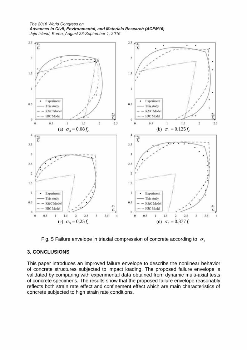
(a) 3 0.08 cf (b) 3 0.125 cf
(c) 3 0.25 cf (d) 3 0.377 cf
Fig. 5 Failure envelope in triaxial compression of concrete according to 3
3. CONCLUSIONS This paper introduces an improved failure envelope to describe the nonlinear behavior of concrete structures subjected to impact loading. The proposed failure envelope is validated by comparing with experimental data obtained from dynamic multi-axial tests of concrete specimens. The results show that the proposed failure envelope reasonably reflects both strain rate effect and confinement effect which are main characteristics of concrete subjected to high strain rate conditions.

ACKNOWLEDGMENT
This research was supported by a grant from a Construction Technology Research Project (Development of impact/blast resistant HPFRCC and evaluation technique thereof) funded by the Ministry on Land, Infrastructure, Transport, the Defense Research Laboratory Program of the Defense Acquisition Program Administration and the Agency for Defense Development of Republic of Korea, Korea Minister of Ministry of Land, Transport and Maritime Affairs (MLTM) as U-City Master and Doctor Course Grant Program.
REFERENCES .Malvar L.J. and Ross C.A. (1998), “Review of strain rate effects for concrete in
tension”, ACI Material Journal, 95(6), 735-739. Grote D.L., Park S.W., Zhou M. (2001), “Dynamic behavior of concrete at high strain
rates and pressures: I. experimental characterization” International Journal of Impact Engineering, 25(9), 869-886.
CEB-FIP (1993), “CEB-FIP Model Code 1990”, Design Code, 25(1). Hallquist, J.O. (2007), “LS-DYNA keyword user’s manual”, Livermore Software
Technology Corporation Karlsson, H. and Sorensen. (2001), “ABAQUS/Standard user's manual. Vol.1”. Fujikake K, et al. (2000), “Dynamic properties of concrete materials with high rates of
tri-axial compressive loads”, Material Structure, Vol. 8, 511-22. Yan, D. and Lin, G. (2007), “Dynamic behavior of concrete in biaxial compression”,
Magazine of Concrete Research, 59(1), 42-52. Kwak H.G., Gang H.G. (2015), “A bi-axial model for concrete under high-strain rate
conditions” Materials characterisation 2015. Wessex institute of technology, 319-330.
Holmquist T.J., Johnson G.R., Cook W.H. (1993), “A computational constitutive model for concrete subjected to large strains, high strain rates, and high pressure”, international symposium on ballistics. Quebec, Canada. International Ballistics Society, 591-600.
Schwer, L.E. and Malvar, L.J. (2005), “Simplified concrete modeling with* MAT_CONCRETE_DAMAGE_REL3”, JRI LS-Dyna User Week.
Kwak H.G., Gang H.G. (2015), “An improved criterion to minimize FE mesh-dependency in concrete structures under high strain rate conditions”, International Journal of Impact Engineering, Vol. 86, 84-95.
Mills L.L., Zimmerman R.M. (1970), “Compressive strength of plain concrete under multiaxial loading conditions”, ACI J, 67(10),802-807.
Ottosen N.S. (1975), “Failure and Elasticity of Concrete”, Danish Atomic Energy Commission, Research Establishment Risö, Risö-M-1801, September 1975;67.


