An Illustration of ESP8266/Raspberry Pi IoT Ecosystem · PDF fileAn Illustration of...
29
An Illustration of ESP8266/Raspberry Pi IoT Ecosystem: ESP8266 as IoT Nodes, RESTful client, MQTT publisher and MQTT subscriber Raspberry Pi 3 running Home Assistant as MQTT subscriber and node.js service By Takyiu Liu Jan 2017
-
Upload
nguyennhan -
Category
Documents
-
view
239 -
download
4
Transcript of An Illustration of ESP8266/Raspberry Pi IoT Ecosystem · PDF fileAn Illustration of...

An Illustration of
ESP8266/Raspberry Pi
IoT Ecosystem:
ESP8266 as IoT Nodes, RESTful client, MQTT publisher
and MQTT subscriber
Raspberry Pi 3 running Home Assistant as MQTT subscriber
and node.js service
By
Takyiu Liu
Jan 2017

Why ESP8266?
The ESP8266 is a low-cost Wi-Fi chip with full TCP/IP stack and MCU (Micro
Controller Unit) capability produced by Shanghai-based Chinese manufacturer, Espressif
Systems. You can use it to provide WiFi access for your Arduino boards very inexpensively; or
you can simply use it by itself. The low cost of ESP8266 makes it ideal for Internet of Things,
and has additional advantages over Arduino Uno with (1) Programmable PWM Frequency (1024
levels), (2) I2C-ing on any of its GPIO pins, (3) abundance of inexpensive modules (at the time
of this writing, Jan 2017, ESP-01 Transceiver board is ~$2.50 and ESP-12E for ~$6).
The nicest thing is that you can program an ESP8266 using the Arduino IDE also.
I try to keep the hardware requirement a minimum to make it easy for anyone to follow.
Specifically, to perform all 5 examples, you only need 2 ESP8266 modules, 1 DHT22
temperature/humidity sensor, 1 10-K resistor, and 1 Raspberry Pi 3 (RPi3).
Example 1 uses just 1 ESP8266.
Example 2 uses just 1 ESP8266.
Example 3 uses 1 ESP8266, DHT22, 10K resistor and RPi3.
Example 3.1 uses 2 ESP8266 DHT22, 10K resistor and RPi3.
Example 4 uses 1 ESP8266, DHT22, 10K resistor and RPi3.
I use DHCP to assign IP addresses to the IoT components. Turns out the first ESP8266
runs at 192.168.1.67; the second ESP8266 runs at 192.168.1.99; and RPi3 runs at 192.168.1.96.
Preparing Arduino IDE for ESP8266 Programming
I am using a NodeMCU Amica ESP-12E dev board.
It comes with a usb-to-serial adapter on the board. There are 2 versions: some have
CP2102, others have CH340 adapters. So install the driver corresponding to your board: CP210x
(https://www.silabs.com/products/mcu/Pages/USBtoUARTBridgeVCPDrivers.aspx) or CH340
(http://www.arduined.eu/ch340-windows-8-driver-download/ ). This allows the Arduino IDE to
see your device.

Steps to install ESP8266 tool chain on your Arduino Integrated Development
Environment are shown here:
Download and install the latest version of Arduino IDE
(https://www.arduino.cc/en/Main/Software ). My screenshots are for Arduino 1.8.1.
Go to File/Preferences/Settings and in the text field Additional Board Manager URLs
enter this URL: http://arduino.esp8266.com/package_esp8266com_index.json. This
allows the board manger of Arduino IDE to look for the definitions for various 8266
modules.

Go to Tools/Board/Boards Manager… and search for your ESP8266 board and click
Install.
Unlike ESP-01 module (for example), ESP-12E comes with the necessary usb-to-
serial converter. When you connect your ESP-12 module to the USB port of your
computer, Arduino detects the module and presents it as a COM port, labeled as
COM#. In my case it shows up as COM3. Go to Tools/Port and select the COM port.
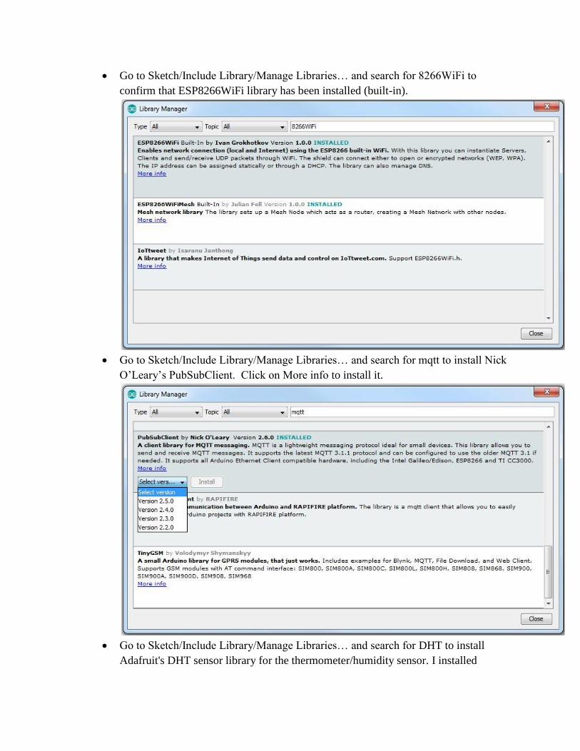
Go to Sketch/Include Library/Manage Libraries… and search for 8266WiFi to
confirm that ESP8266WiFi library has been installed (built-in).
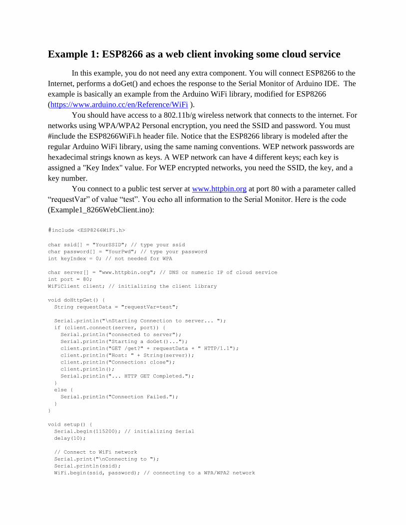
Go to Sketch/Include Library/Manage Libraries… and search for mqtt to install Nick
O’Leary’s PubSubClient. Click on More info to install it.
Go to Sketch/Include Library/Manage Libraries… and search for DHT to install
Adafruit's DHT sensor library for the thermometer/humidity sensor. I installed

version 1.2.3.
Go to Sketch/Include Library/Manage Libraries… and search for arest. Click on
More info to install aREST library by Mark Schwartz.

In Tools, select the ESP8266 board:
Example 1: ESP8266 as a web client invoking some cloud service
In this example, you do not need any extra component. You will connect ESP8266 to the
Internet, performs a doGet() and echoes the response to the Serial Monitor of Arduino IDE. The
example is basically an example from the Arduino WiFi library, modified for ESP8266
(https://www.arduino.cc/en/Reference/WiFi ).
You should have access to a 802.11b/g wireless network that connects to the internet. For
networks using WPA/WPA2 Personal encryption, you need the SSID and password. You must
#include the ESP8266WiFi.h header file. Notice that the ESP8266 library is modeled after the
regular Arduino WiFi library, using the same naming conventions. WEP network passwords are
hexadecimal strings known as keys. A WEP network can have 4 different keys; each key is
assigned a "Key Index" value. For WEP encrypted networks, you need the SSID, the key, and a
key number.
You connect to a public test server at www.httpbin.org at port 80 with a parameter called
“requestVar” of value “test”. You echo all information to the Serial Monitor. Here is the code
(Example1_8266WebClient.ino):
#include <ESP8266WiFi.h>
char ssid[] = "YourSSID"; // type your ssid
char password[] = "YourPwd"; // type your password
int keyIndex = 0; // not needed for WPA
char server[] = "www.httpbin.org"; // DNS or numeric IP of cloud service
int port = 80;
WiFiClient client; // initializing the client library
void doHttpGet() {
String requestData = "requestVar=test";
Serial.println("\nStarting Connection to server... ");
if (client.connect(server, port)) {
Serial.println("connected to server");
Serial.println("Starting a doGet()...");
client.println("GET /get?" + requestData + " HTTP/1.1");
client.println("Host: " + String(server));
client.println("Connection: close");
client.println();
Serial.println("... HTTP GET Completed.");
}
else {
Serial.println("Connection Failed.");
}
}
void setup() {
Serial.begin(115200); // initializing Serial
delay(10);
// Connect to WiFi network
Serial.print("\nConnecting to ");
Serial.println(ssid);
WiFi.begin(ssid, password); // connecting to a WPA/WPA2 network

while (WiFi.status() != WL_CONNECTED) {
delay(500);
Serial.print(".");
}
Serial.println("\nWiFi connected");
Serial.print("SSID: ");
Serial.println(WiFi.SSID());
long rssi = WiFi.RSSI();
Serial.print("Signal Strength (RSSI): ");
Serial.print(rssi);
Serial.println(" dBm");
Serial.print("IP address: ");
Serial.println(WiFi.localIP());
Serial.println();
doHttpGet();
}
void loop() {
if (client.available()) {
Serial.println("HTTP Response");
}
// echoing any incoming bytes to Serial
while (client.available()) {
char c = client.read();
Serial.write(c);
}
if (!client.connected()) {
Serial.println();
Serial.print("Disconnecting from Server");
client.stop();
}
delay(10000);
}
The loop() function loops forever. The first time it goes through, you’ll see Serial
Monitor output like this (IP address is that of the ESP8266):
Connecting to YourSSID
.....
WiFi connected
SSID: YourSSID
Signal Strength (RSSI): -46 dBm
IP address: 192.168.1.67
Starting Connection to server...
connected to server
Starting a doGet()...
... HTTP GET Completed.
Subsequently loop() will give you the rest of the Serial Monitor output: HTTP Response
HTTP/1.1 200 OK
Server: nginx
Date: Sun, 22 Jan 2017 21:34:02 GMT
Content-Type: application/json
Content-Length: 182
Connection: close
Access-Control-Allow-Origin: *

Access-Control-Allow-Credentials: true
{
"args": {
"requestVar": "test"
},
"headers": {
"Host": "www.httpbin.org"
},
"origin": "XX.XX.XX.XX",
"url": "http://www.httpbin.org/get?requestVar=test"
}
Disconnecting from Server
Disconnecting from Server
Disconnecting from Server
Example 2: ESP8266 as a web server In this example, you’ll run a web server on the ESP8266. Using the ESP8266WiFi library,
your ESP8266 will be able to answer a HTTP request. A user can go to a web browser and
instruct ESP8266 to perform some I/O control (turning a LED on and off, for example).
On the ESP-12E module, there is a blue LED connected to GPIO pin 2. DigitalWriting a
LOW at pin 2 will turn on the LED, HIGH will turn off the LED. You use
request.indexOf(“/LED=ON”) to see if the string “/LED=ON” is part of the request URL (if the
index after search is not -1, there is a match). The code (Example2_8266WebServer.ino) is here:
#include <ESP8266WiFi.h>
char ssid[] = "YourSSID"; // type your ssid
char password[] = "YourPwd"; // type your password
int keyIndex = 0; // for WEP only
int ledPin = 2; // GPIO2 of ESP8266
WiFiServer server(80); // initializing the server
void setup() {
Serial.begin(115200);
delay(10);
pinMode(ledPin, OUTPUT);
digitalWrite(ledPin, HIGH); // turning off LED
// Connect to WiFi network
Serial.print("\nConnecting to ");
Serial.println(ssid);
WiFi.begin(ssid, password); // connect to WPA/WPA2 network
while (WiFi.status() != WL_CONNECTED) {
delay(500);
Serial.print(".");
}
Serial.println("\nWiFi connected");
Serial.print("SSID: ");
Serial.println(WiFi.SSID());
long rssi = WiFi.RSSI();
Serial.print("Signal Strength (RSSI): ");
Serial.print(rssi);
Serial.println(" dBm");
Serial.print("IP address: ");
Serial.println(WiFi.localIP());
Serial.println();
// Start the server
server.begin();
Serial.println("Server started");
// Print the IP address
Serial.print("Use this URL to connect: ");
Serial.print(" http://");
Serial.print(WiFi.localIP());
Serial.println("/");
}
void loop() {
// Check if a client has connected
WiFiClient client = server.available();
if (!client) {
return;
}
// Wait until the client sends some data
Serial.println("new client");
while(!client.available()){
delay(1);
}
// Read the first line of the request
String request = client.readStringUntil('\r');
Serial.println(request);
client.flush();
// Match the request to see if client wants to turn ON or OFF the LED
// digitalWrite LOW to turn on LED, HIGH to turn off LED
int value = HIGH;
if (request.indexOf("/LED=ON") != -1) {
digitalWrite(ledPin, LOW);
value = LOW;
}
if (request.indexOf("/LED=OFF") != -1){
digitalWrite(ledPin, HIGH);
value = HIGH;
}
// Return the response HTML
client.println("HTTP/1.1 200 OK");
client.println("Content-Type: text/html");
client.println(); // do not forget this one
client.println("<!DOCTYPE HTML>");
client.println("<html>");
client.print("Blue LED at pin 2 is now: ");
if (value == LOW) {
client.print("ON");
} else {
client.print("OFF");
}
client.println("<br><br>");
client.println("Click <a href=\"/LED=ON\">here</a> to turn ON the LED on pin 2<br>");
client.println("Click <a href=\"/LED=OFF\">here</a> to turn OFF the LED on pin 2<br>");
client.println("</html>");
delay(1); // give browser time to receive data
Serial.println("Client disconnected");
Serial.println();
}
Turing on the LED and off will give you a Serial Monitor trace like this:
Connecting to YourSSID
....
WiFi connected
SSID: YourSSID
Signal Strength (RSSI): -45 dBm
IP address: Server started
Use this URL to connect: http://192.168.1.67/
new client
GET /LED=ON HTTP/1.1

Client disconnected
new client
GET /favicon.ico HTTP/1.1
Client disconnected
new client
GET /LED=OFF HTTP/1.1
Client disconnected
new client
GET /favicon.ico HTTP/1.1
Client disconnected
With HTML source:

Example 3: ESP8266 as a MQTT publisher; Home Assistant as a
MQTT subscriber
In this example, you can see a more systematic ecosystem of IoT where there is a
message hub for messaging to take place. Think of the hub as a holding place for messages (like
temperature, humidity data) – interested parties come along and either place or pick up messages
there. Some will be message producers (we call them publishers); there are also message
consumers (we call them subscribers). So the publishers produce data, the subscriber(s) (can be
more than one) pick up the data asynchronously and decide how to respond. In this example the
publisher will be ESP8266 publishing temperature and humidity data, the subscriber will be
Home Assistant, an open-sourced Python environment for home automation, where it simply
produces a running graph for the retrieved data. The MQTT broker will be an embedded MQTT
broker started by Home Assistant itself. See the next section on Home Assistant for more
details.
I am using a DHT22 sensor for generating temperature and humidity data. The DHT22 is
a basic, low-cost digital temperature and humidity sensor. It uses a capacitive humidity sensor
and a thermistor to measure the surrounding air, and generates a digital signal on the data pin (no
analog input pins needed).
Connections are simple, the first pin on the left is connected to 3-5V power supply, the
second pin to your data input pin (I use GPIO14, labeled as D5 on the module) and the right most
pin to ground. Note that you need to connect a 10K pull-up resistor on the data pin to Vcc (the
green line is the data line, diagram is from Manufacturer for connecting to Uno):
I customize the loop() function by Paulus Schoutsen for my environment. The Home
Assistant web site contains a lot of information on Home Assistant. You can find the
information here: https://home-assistant.io/blog/2015/10/11/measure-temperature-with-esp8266-
and-report-to-mqtt/#disqus_thread . Note that ESP8266 connects to the MQTT broker as
"ESP8266Publisher1". The code (Example3_8266MQTTPublisher.ino) is here:

// - PubSubClient library by Nick ‘O Leary
// - DHT sensor library by Adafruit
#include <ESP8266WiFi.h>
#include <PubSubClient.h>
#include <DHT.h>
#define DHTTYPE DHT22
char ssid[] = "YourSSID"; //type your ssid
char password[] = "YourPwd"; // type your password
int keyIndex = 0; // not needed for WPA
char mqtt_server[] = "192.168.1.96" ; // specify where the MQTT server is running
int mqtt_port = 1883; // MQTT port
char mqtt_user[] = "homeassistant"; // MQTT user
char mqtt_password[] = "MQTTPwd"; // MQTT pwd
char humidity_topic[] = "sensor/humidity"; // humidity topic
char temperature_topic[] = "sensor/temperature"; // temperature topic
int DHTPIN = 14;
WiFiClient wifiClient;
PubSubClient client(wifiClient);
DHT dht(DHTPIN, DHTTYPE); // initializing the sensor
void setup_wifi() {
Serial.print("\nConnecting to ");
Serial.println(ssid);
WiFi.begin(ssid, password); // connect to WPA/WPA2 network
while (WiFi.status() != WL_CONNECTED) {
delay(500);
Serial.print(".");
}
Serial.println("\nWiFi connected");
Serial.print("SSID: ");
Serial.println(WiFi.SSID());
long rssi = WiFi.RSSI();
Serial.print("Signal Strength (RSSI): ");
Serial.print(rssi);
Serial.println(" dBm");
Serial.print("IP address: ");
Serial.println(WiFi.localIP());
Serial.println();
}
void reconnect() {
// Loop until we're reconnected
while (!client.connected()) {
Serial.print("Attempting MQTT connection...");
if (client.connect("ESP8266Publisher1", mqtt_user, mqtt_password)) {
Serial.println("connected");
}
else {
Serial.print("failed, rc=");
Serial.print(client.state());
Serial.println(" will try again in 5 seconds");
delay(5000);
}
}
}
bool checkBound(float newValue, float prevValue, float minChange) {
return !isnan(newValue) &&
(newValue < prevValue - minChange || newValue > prevValue + minChange);
}
long lastMsg = 0;
float temp = 0.0;
float hum = 0.0;
float temp_diff = 0.1;
float hum_diff = 1.0;
void setup() {
Serial.begin(115200);
delay(10);
dht.begin();
setup_wifi();
client.setServer(mqtt_server, mqtt_port);
}
void loop() {
if (!client.connected()) {
reconnect();
}
// client.loop() called regularly to allow the client to process incoming messages
// and maintain its connection to the server.
client.loop();
long now = millis();
if (now - lastMsg > 2000) {
lastMsg = now;
float newTemp = dht.readTemperature();
float newHum = dht.readHumidity();
if (checkBound(newTemp, temp, temp_diff)) {
temp = newTemp;
Serial.print("New temperature:");
Serial.println(String(temp).c_str());
client.publish(temperature_topic, String(temp).c_str(), true);
}
if (checkBound(newHum, hum, hum_diff)) {
hum = newHum;
Serial.print("New humidity:");
Serial.println(String(hum).c_str());
client.publish(humidity_topic, String(hum).c_str(), true);
}
}
}
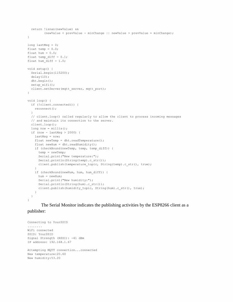
The Serial Monitor indicates the publishing activities by the ESP8266 client as a
publisher:
Connecting to YourSSID
........
WiFi connected
SSID: YourSSID
Signal Strength (RSSI): -41 dBm
IP address: 192.168.1.67
Attempting MQTT connection...connected
New temperature:20.60
New humidity:53.20

Those data points now reside on the MQTT broker. To make use of those data, we need
a MQTT subscriber.

Running Home Assistant on a Raspberry Pi 3 as a MQTT
subscriber
Home Assistant is python’s approach for home automation. I chose Raspberry Pi 3
(RPi3) to run Home Assistant because it comes with onboard WiFi and is much faster compared
to the original Raspberry Pi. It is a bargain at $40. To prepare the RPi3, download the OS,
Raspbian Jessie with Pixel at https://downloads.raspberrypi.org/raspbian_latest (kernel version
4.4) and write the image to a SD card like Samsung EVO 64GB Micro SDXC with
Win32DiskImager (download at https://sourceforge.net/projects/win32diskimager/ ).
The first time you boot up Pi 3, you log in as user pi, with password preset to be
raspberry. Connect the built-in WiFi with your SSID and password for wireless connection to the
Internet. Make some essential changes on the settings in raspi-config (sudo raspi-config):
Expand the FileSystem to resize the root partition
Localisation Options to use a US keyboard
Change the timezone
Start a manual installation of Home Assistant on the Pi 3:
Change the default password (passwd)
Keep the software up to date o sudo apt-get update
o sudo apt-get upgrade -y
o sudo apt-get autoclean
o sudo apt-get autoremove
Home Assistant is python’s approach to do home automation. You will therefore need to
prepare the Python 3 environment on Pi 3. o sudo apt-get install python3 python3-venv python3-pip
You want to create a separate user, homeassistant, to manage Home Assistant on a
daily basis. The installation of Home Assistant will be under a directory,
/srv/homeassistant, owned by this account. In useradd, -r is for creating a system
account, -m for creating the home directory for this system account. o sudo useradd -rm homeassistant
Create the homeassistant directory under /srv and change the owner to account
homeassistant. For example, the following would change the owner of a file named
file2 to the user with the user name bob and changes its group to group2: chown bob:group2 file2
o cd /srv
o sudo mkdir homeassistant
o sudo chown homeassistant:homeassistant homeassistant
virtualenv is a tool to create isolated Python environments. virtualenv creates a folder
which contains all the necessary executables to use the packages that a Python project
would need. You want to create such an isolated virtual Python environment to shield

Home Assistant from any future changes of Python configuration on your Pi 3. You do
all this as the user homeassistant. o sudo su -s /bin/bash homeassistant
o cd /srv/homeassistant
o python3 -m venv homeassistant_venv
o source /srv/homeassistant/homeassistant_venv/bin/activate
Once you have activated the virtual Python environment, the prompt will change. You
are now ready to install Home Assistant into the /srv/homeassistant directory. o (homeassistant_venv) homeassistant@raspberrypi:/srv/homeassistant
$ pip3 install homeassistant
Now start Home Assistant for the very first time to complete the installation. It will
create the .homeassistant directory in the /home/homeassistant directory and create
all necessary dependencies.
o (homeassistant_venv) homeassistant@raspberrypi:/srv/homeassistant
$ hass
Note: for future day-to-day administration, if you ever need to restart Home Assistant,
remember to always use the su command to start Home Assistant as homeassistant. o sudo su -s /bin/bash homeassistant
o cd /srv/homeassistant
o python3 -m venv homeassistant_venv
o source /srv/homeassistant/homeassistant_venv/bin/activate
o (homeassistant_venv) homeassistant@raspberrypi:/srv/homeassistant
$ hass
It takes a few minutes for Home Assistant to come up. Once it is up and running, you
can bring up a web page at http://192.168.1.96:8123/states (replace 192.168.1.96
with your IP address of the Pi 3 – use ifconfig to figure out what IP address your Pi 3 is
bound to) :

You can see the data collected for “Sun” and a “sensor (on yr platform)” icons because
they have been pre-defined in configuration.yaml inside the directory
/home/homeassistant/.homeassistant. At this point you will not see the center 2
icons yet:
You need to add the following entries (mqtt and 2 sensors) at the end in the
configuration.yaml file (use nano editor, for example) to subscribe data (published by
ESP8266) on the MQTT broker. The configuration will look like this:
mqtt:

sensor 2:
platform: mqtt
name: "Temperature"
state_topic: "sensor/temperature"
qos: 0
unit_of_measurement: "ºC"
sensor 3:
platform: mqtt
name: “Humidity”
state_topic: “sensor/humidity”
qos: 0
unit_of_measurement: “%”
Notice that mqtt is defned but not configured. This way Home Assistant will start an
internal, embedded message broker called HBMQTT
(https://pypi.python.org/pypi/hbmqtt) and subscribe to it. Inside the ESP8266 code, you
send messages to this HBMQTT broker, using the following information:
o Host is the IP address of the RPi3
o Port is 1883
o Protocol is 3.1.1
o User is homeassistant
o Password is your system password
Notice you also add 2 topics here for your thermometer data and humidity data. Home
Assistant will subscribe to these 2 topics and present the data as two extra icons in the
center.
The DHT22 sensor produces the temperature and humidity data; you can see the
Humidity and Temperatures data here. If you click on these icons, a running graph will
be presented:

Home Assistant can do a lot more than just subscribing to the sensor data; I am just
showing its role here as a MQTT subscriber.
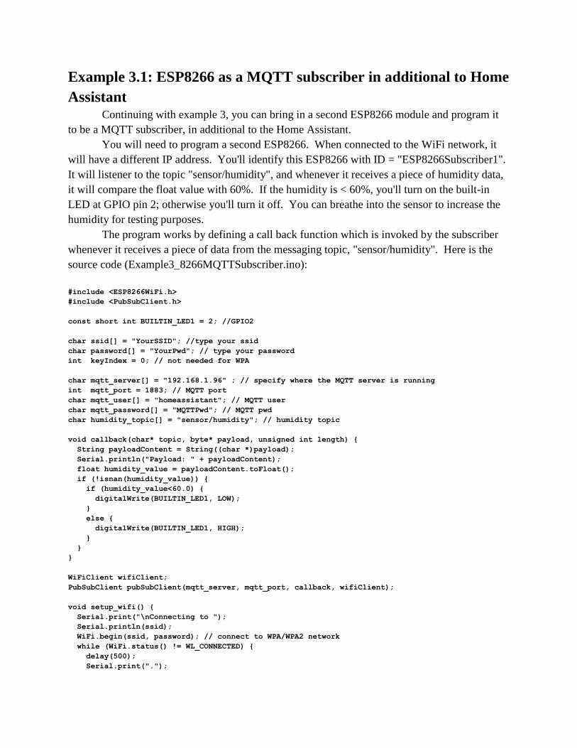
Example 3.1: ESP8266 as a MQTT subscriber in additional to Home
Assistant Continuing with example 3, you can bring in a second ESP8266 module and program it
to be a MQTT subscriber, in additional to the Home Assistant.
You will need to program a second ESP8266. When connected to the WiFi network, it
will have a different IP address. You'll identify this ESP8266 with ID = "ESP8266Subscriber1".
It will listener to the topic "sensor/humidity", and whenever it receives a piece of humidity data,
it will compare the float value with 60%. If the humidity is < 60%, you'll turn on the built-in
LED at GPIO pin 2; otherwise you'll turn it off. You can breathe into the sensor to increase the
humidity for testing purposes.
The program works by defining a call back function which is invoked by the subscriber
whenever it receives a piece of data from the messaging topic, "sensor/humidity". Here is the
source code (Example3_8266MQTTSubscriber.ino):
#include <ESP8266WiFi.h>
#include <PubSubClient.h>
const short int BUILTIN_LED1 = 2; //GPIO2
char ssid[] = "YourSSID"; //type your ssid
char password[] = "YourPwd"; // type your password
int keyIndex = 0; // not needed for WPA
char mqtt_server[] = "192.168.1.96" ; // specify where the MQTT server is running
int mqtt_port = 1883; // MQTT port
char mqtt_user[] = "homeassistant"; // MQTT user
char mqtt_password[] = "MQTTPwd"; // MQTT pwd
char humidity_topic[] = "sensor/humidity"; // humidity topic
void callback(char* topic, byte* payload, unsigned int length) {
String payloadContent = String((char *)payload);
Serial.println("Payload: " + payloadContent);
float humidity_value = payloadContent.toFloat();
if (!isnan(humidity_value)) {
if (humidity_value<60.0) {
digitalWrite(BUILTIN_LED1, LOW);
}
else {
digitalWrite(BUILTIN_LED1, HIGH);
}
}
}
WiFiClient wifiClient;
PubSubClient pubSubClient(mqtt_server, mqtt_port, callback, wifiClient);
void setup_wifi() {
Serial.print("\nConnecting to ");
Serial.println(ssid);
WiFi.begin(ssid, password); // connect to WPA/WPA2 network
while (WiFi.status() != WL_CONNECTED) {
delay(500);
Serial.print(".");

}
Serial.println("\nWiFi connected");
Serial.print("SSID: ");
Serial.println(WiFi.SSID());
long rssi = WiFi.RSSI();
Serial.print("Signal Strength (RSSI): ");
Serial.print(rssi);
Serial.println(" dBm");
Serial.print("IP address: ");
Serial.println(WiFi.localIP());
Serial.println();
}
void reconnect() {
// Loop until we're reconnected
while (!pubSubClient.connected()) {
Serial.print("Attempting MQTT connection...");
if (pubSubClient.connect("ESP8266Subscriber1", mqtt_user, mqtt_password)) {
Serial.println("Connection to MQTT broker successful");
pubSubClient.subscribe(humidity_topic);
Serial.println("Successfully subscribed to: " + (String) humidity_topic);
}
else {
Serial.print("failed, rc=");
Serial.print(pubSubClient.state());
Serial.println(" will try again in 5 seconds");
delay(5000);
}
}
}
void setup() {
pinMode(BUILTIN_LED1, OUTPUT); // Initialize the BUILTIN_LED1 pin as an output
Serial.begin(115200);
delay(10);
setup_wifi();
pubSubClient.setServer(mqtt_server, mqtt_port);
}
void loop() {
if (!pubSubClient.connected()) {
reconnect();
}
// pubSubClient.loop() called regularly to allow the pubSubClient to subscribe messages
// and maintain its connection to the server.
pubSubClient.loop();
}
After the second ESP8266 is started, it starts receiving the humidity data from the MQTT
broker:
Connecting to ATT295G4jA
.....
WiFi connected
SSID: ATT295G4jA
Signal Strength (RSSI): -46 dBm
IP address: 192.168.1.99
Attempting MQTT connection...Connection to MQTT broker successful
Successfully subscribed to: sensor/humidity

Payload: 48.20
Payload: 50.00
Payload: 48.90
You'll notice that whenever the humidity drops below 60%, the built-in LED will be
turned on; otherwise it will be turned off.

Example 4: ESP8266 as a web server exposing RESTful api;
Raspberry Pi 3 running as a RESTful client and node.js server In example 2, ESP8266 runs a web server and takes requests to control the state of a
LED. You can also provide RESTful api to the web server so anyone can query the temperature
and humidity data on the sensor attached to ESP8266 by making lightweight RESTful calls. You
can prepare a node.js server on RPi3, polling the RESTful api on ESP8266 periodically and
serving the results on a web page.
You connect the DHT22 sensor the same way you do in example 3. Here is the code for
ESP8266 (Example4_8266REST_RPi3Node.ino):
#include <ESP8266WiFi.h>
#include <DHT.h>
#include <aREST.h>
#define DHTTYPE DHT22
#define DHTPIN 14
aREST rest = aREST(); // create aREST instance
char ssid[] = "YourSSID"; //type your ssid
char password[] = "YourPwd"; // type your password
int keyIndex = 0; // not needed for WPA
DHT dht(DHTPIN, DHTTYPE); // initializing the sensor
#define LISTEN_PORT 80 // port to listen for incoming TCP connections
WiFiServer server(LISTEN_PORT); // initializing the server
int temperature;
int humidity;
void setup(void)
{
Serial.begin(115200);
delay(10);
dht.begin();
// sensor_module/temperature gives you temperature data
// sensor_module/humidity gives you humidity data
rest.variable("temperature",&temperature); // Initiating variables and expose them to REST api
rest.variable("humidity",&humidity);
rest.set_id("1"); // device ID
rest.set_name("sensor_module"); // device name
// Connect to WiFi network
Serial.print("\nConnecting to ");
Serial.println(ssid);
WiFi.begin(ssid, password); // connect to WPA/WPA2 network
while (WiFi.status() != WL_CONNECTED) {
delay(500);
Serial.print(".");
}
Serial.println("\nWiFi connected");
Serial.print("SSID: ");
Serial.println(WiFi.SSID());
long rssi = WiFi.RSSI();

Serial.print("Signal Strength (RSSI): ");
Serial.print(rssi);
Serial.println(" dBm");
Serial.print("IP address: ");
Serial.println(WiFi.localIP());
Serial.println();
// Start the server
server.begin();
Serial.println("Server started");
// Print the IP address
Serial.print("Use this URL to connect: ");
Serial.print(" http://");
Serial.print(WiFi.localIP());
Serial.println("/");
}
void loop() {
temperature = dht.readTemperature();
humidity = dht.readHumidity();
// Check if Raspberry Pi has connected
WiFiClient client = server.available();
if (!client) {
return;
}
// Wait until Raspberry Pi sends some data
Serial.println("new RPi Connection");
while(!client.available()){
delay(1);
}
rest.handle(client);
}
To prepare the Pi 3 to run node.js, do the following:
Use Marco Schwartz's github files at
https://github.com/openhomeautomation/connect-esp8266-rpi/tree/master/interface
Prepare a directory like this on your RPi3 my_server/interface/public/css/interface.css
my_server/interface/public/js/interface.js
my_server/interface/views/interface.jade
my_server/interface/app.js
You will start your node.js server in the directory my_server.
The files are listed here for your convenience:
interface.css: .voffset { margin-top: 30px; }
body {
font-size: 30px;
}
interface.js (you can see we are polling data every 5 seconds): $(document).ready(function() {
refreshSensors();
setInterval(refreshSensors, 5000);

});
function refreshSensors() {
$.get('/sensor_module/temperature', function(json_data) {
$("#temperature").text('Temperature: ' + json_data.temperature + ' C');
$.get('/sensor_module/humidity', function(json_data) {
$("#humidity").text('Humidity: ' + json_data.humidity + ' %');
});
});
}
interface.jade (template file, we should be using pug now): doctype
html
head
title Raspberry Pi Interface
link(rel='stylesheet',
href="https://maxcdn.bootstrapcdn.com/bootstrap/3.3.0/css/bootstrap.min.css")
link(rel='stylesheet', href="/css/interface.css")
script(src="https://code.jquery.com/jquery-2.1.1.min.js")
script(src="/js/interface.js")
body
.container
h1 Raspberry Pi Sensors
.row.voffset
.col-md-6
div#temperature Temperature:
.col-md-6
div#humidity Humidity:
The node.js will run at port 3000. Here is the app.js file (you need to change the IP
address to that of your ESP8266 IP address): // Imports
var express = require('express');
var app = express();
// View engine
app.set('view engine', 'jade');
// Set public folder
app.use(express.static(__dirname + '/public'));
// node-aREST
var rest = require("arest")(app);
rest.addDevice('http','192.168.1.67');
// Interface routes
app.get('/', function(req, res){
res.render('interface');
});
// Start server
var server = app.listen(3000, function() {
console.log('Listening on port %d', server.address().port);
});
To install node.js on RPi3 with Adafruit's RPi package repository: o curl -sLS https://apt.adafruit.com/add | sudo bash
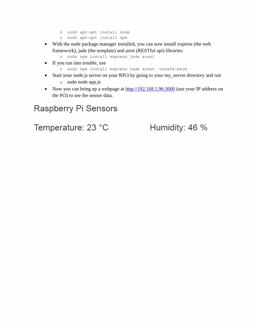
o sudo apt-get install node
o sudo apt-get install npm
With the node package manager installed, you can now install express (the web
framework), jade (the template) and arest (RESTful api) libraries: o sudo npm install express jade arest
If you run into trouble, use o sudo npm install express jade arest –unsafe-perm
Start your node.js server on your RPi3 by going to your my_server directory and run
o sudo node app.js
Now you can bring up a webpage at http://192.168.1.96:3000 (use your IP address on
the Pi3) to see the sensor data.