An FPGA Architecture for the Recovery of...
26
An FPGA Architecture for the Recovery of WPA/WPA2 Keys ¤ Tyler Johnson † , Daniel Roggow ‡ , Phillip H. Jones § and Joseph Zambreno ¶ Department of Electrical & Computer Engineering, Iowa State University, 2215 Coover Hall, Ames, IA 50011, USA † [email protected] ‡ [email protected] § [email protected] ¶ [email protected] Received 22 August 2014 Accepted 14 April 2015 Published 21 May 2015 Wi-Fi protected access (WPA) has provided serious improvements over the now deprecated wired equivalent privacy (WEP) protocol. WPA, however, still has some °aws that allow an attacker to obtain the passphrase. One of these °aws is exposed when the access point (AP) is operating in the WPA personal mode. This is the most common mode, as it is the quickest and easiest to con¯gure. This vulnerability requires the attacker to capture the tra±c from the four-way handshake between the AP and client, and then have enough compute time to reverse the passphrase. Increasing the rate at which passphrases can be reversed reduces the amount of time required to construct a repository of service set identi¯ers (SSIDs) and passphrases, which can increase the chances an attack is successful, or, alternatively, reduce the di±culty of auditing a wireless network for security purposes. This work focuses on creating an ¯eld programmable gate array (FPGA)-based architecture to accelerate the generation of a WPA/WPA2 pairwise master key (PMK) lookup table (LUT) for the re- covery of the passphrase, with special emphasis on the secure hash algorithm-1 (SHA-1) implementation. PMK generation relies heavily on SHA-1 hashing and, as this work shows, an optimized SHA-1 implementation can achieve up to a 40 speedup over an unoptimized implementation when generating PMKs. Keywords: Recon¯gurable computing; FPGA; SHA-1; convey; Wi-Fi security; dictionary attack; WPA/WPA2 authentication. *This paper was recommended by Regional Editor Emre Salman. ¶ Corresponding author. Journal of Circuits, Systems, and Computers Vol. 24, No. 7 (2015) 1550105 (26 pages) # . c World Scienti¯c Publishing Company DOI: 10.1142/S0218126615501054 1550105-1
Transcript of An FPGA Architecture for the Recovery of...
An FPGA Architecture for the Recovery
of WPA/WPA2 Keys¤
Tyler Johnson†, Daniel Roggow‡, Phillip H. Jones§
and Joseph Zambreno¶
Department of Electrical & Computer Engineering,
Iowa State University,
2215 Coover Hall, Ames, IA 50011, USA†[email protected]‡[email protected]§[email protected]
Received 22 August 2014
Accepted 14 April 2015Published 21 May 2015
Wi-Fi protected access (WPA) has provided serious improvements over the now deprecated
wired equivalent privacy (WEP) protocol. WPA, however, still has some °aws that allow an
attacker to obtain the passphrase. One of these °aws is exposed when the access point (AP) isoperating in the WPA personal mode. This is the most common mode, as it is the quickest
and easiest to con¯gure. This vulnerability requires the attacker to capture the tra±c from
the four-way handshake between the AP and client, and then have enough compute time to
reverse the passphrase. Increasing the rate at which passphrases can be reversed reduces theamount of time required to construct a repository of service set identi¯ers (SSIDs) and
passphrases, which can increase the chances an attack is successful, or, alternatively, reduce
the di±culty of auditing a wireless network for security purposes. This work focuses oncreating an ¯eld programmable gate array (FPGA)-based architecture to accelerate the
generation of a WPA/WPA2 pairwise master key (PMK) lookup table (LUT) for the re-
covery of the passphrase, with special emphasis on the secure hash algorithm-1 (SHA-1)
implementation. PMK generation relies heavily on SHA-1 hashing and, as this work shows,an optimized SHA-1 implementation can achieve up to a 40� speedup over an unoptimized
implementation when generating PMKs.
Keywords: Recon¯gurable computing; FPGA; SHA-1; convey; Wi-Fi security; dictionary
attack; WPA/WPA2 authentication.
*This paper was recommended by Regional Editor Emre Salman.¶Corresponding author.
Journal of Circuits, Systems, and ComputersVol. 24, No. 7 (2015) 1550105 (26 pages)
#.c World Scienti¯c Publishing Company
DOI: 10.1142/S0218126615501054
1550105-1
1. Introduction
Wi-Fi protected access (WPA) was created to replace the wired equivalent privacy
(WEP) protocol after it was proven to be insecure.a WPA ¯xed many issues with the
design of WEP, but still has a few issues of its own. The vulnerability speci¯cally
targeted in this paper requires the access point (AP) to be operating in pre-shared
key (PSK) mode, also known as personal mode. If an attacker can capture the
network tra±c representing an authentication between an AP and a client which is
trying to authenticate, the attacker can then recover the PSK required to authen-
ticate with the AP.
The work presented in this paper focuses on constructing a ¯eld programmable
gate array (FPGA)-based architecture, with the purpose of speeding up the time-to-
recovery of a PSK upon capture of the authentication tra±c. At the most basic level,
improving the performance of the recovery of PSKs increases the number of pairwise
master keys (PMKs) generated per second that can be tested for a given service set
identi¯er (SSID). As a result, the time necessary to pre-compute a lookup table
(LUT) of passphrases for an SSID is reduced. For an attacker, this means that the
likelihood of executing a successful dictionary attack against a given AP increases,
and also allows an attacker to more rapidly determine if a given wireless network is
hard to crack. Conversely, a wireless network can be audited faster for passphrase
and/or SSID security, thereby decreasing the chances of success for an attacker. Our
experimental results using the Convey HC-2 hybrid core computer indicate the most
performance-critical component of a WPA-cracking architecture is the secure hash
algorithm-1 (SHA-1) implementation. Using an optimized SHA-1 component, our
design can achieve a 40� speedup over an unoptimized implementation.
This article is organized in the following manner: Section 2 provides an overview
of related work. Section 3 brie°y introduces the methods in which the PSK can be
recovered. Section 4 provides an analysis of the attack space. Section 5 is an overview
of the WPA protocol. Section 6 introduces the recon¯gurable architecture used in
this work. Section 7 describes our PMK generation architecture. Section 8 analyzes
the performance of this architecture. Finally, Sec. 9, concludes the paper by sum-
marizing our contributions and ¯ndings.
2. Related Work
Much attention has been paid to wireless security, and there are several well-known
attacks on Wi-Fi protection schemes. The chopchop attack is a method to decrypt
WEP packets by using a byte-by-byte guess-and-check methodology.1–3 The Beck–
Tews attack is a modi¯ed chopchop attack targeting WPA using the temporal key
integrity protocol (TKIP) to decrypt address resolution protocol (ARP) packets.2,3
a IEEE Std 802.11i-2004 Amendment 6: Medium Access Control (MAC) Security Enhancements, IEEEstandard, IEEE-SA Standards Board (2004).
T. Johnson et al.
1550105-2

The Ohigashi–Morii attack expands upon the Beck–Tews attack, turning it into a
man-in-the-middle attack that does not rely on the IEEE 802.11e QoS feature.2,4 The
Halvorsen–Haugen attack also extends the Beck–Tews method by also decrypting
DHCP ACK packets, as well as proposing methods to cause a denial-of-service attack
and an ARP poisoning attack.2,5 The Hole196 attack exploits a weakness in WPA2
when using group temporal keys (GTKs) whereby a malicious insider uses ARP
poisoning to have the AP redirect decrypted data from authorized users to his or her
machine.b Lastly, brute-force attacks are used to attack WPA/WPA2 using a PSK
by attempting to match a pre-computed PSK from a library to a captured hand-
shake.2
Wireless brute-force attacks have been implemented on CPUs in the form of
applications such as coWPAtty6 and Aircrack.c Pyritd is a faster implementation of
the dictionary attack implemented on GPUs. Finally, the OpenCiphers Project7 has
an FPGA implementation of the brute-force dictionary attack.
Since the SHA is a key component of many cryptosystems, including the IEEE
802.11 standard in WPA mode, much research has been done to accelerate the
algorithm. Hardware implementations of the SHA have focused on error detection
and correction,8 as well as throughput optimization.9,10
3. The Attack Process
The attack carried out in this work is a dictionary attack, which is a style of brute
force attack. The attack can only be successful against an AP that has chosen a
passphrase that exists in the dictionary, since searching the entire possible pass-
phrase space would be computationally prohibitive.
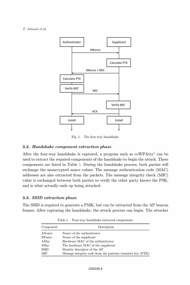
3.1. WPA handshake capture phase
The ¯rst phase is to capture the WPA four-way handshake tra±c (Fig. 1), which can
be accomplished in one of two ways. The ¯rst is to simply monitor the Wi-Fi tra±c in
the area, until a device attempts to authenticate with the targeted AP. This method
is a passive approach and is completely undetectable by the AP. The second option is
an active approach and involves forcibly disconnecting a current client from the
targeted AP. This is done by sending a deauthentication packet to the client with a
spoofed address from the attacker. This causes the client to disconnect from the AP
and reconnect. As the device reconnects, the four-way handshake can then be cap-
tured. Forcibly disconnecting a client can speed up the capture time, but is possible
to detect.
bWPA2 Hole196 vulnerability: Exploits and remediation strategies, whitepaper, AirTight Networks, Inc.(2010).cHome, Aircrack-ng (accessed December 2013) www.aircrack-ng.org.dProject Home, pyrit (accessed December 2013) code.google.com/p/pyrit.
An FPGA Architecture for the Recovery of WPA/WPA2 Keys
1550105-3
3.2. Handshake component extraction phase
After the four-way handshake is captured, a program such as coWPAtty6 can be
used to extract the required components of the handshake to begin the attack. These
components are listed in Table 1. During the handshake process, both parties will
exchange the unencrypted nonce values. The message authentication code (MAC)
addresses are also extracted from the packets. The message integrity check (MIC)
value is exchanged between both parties to verify the other party knows the PSK,
and is what actually ends up being attacked.
3.3. SSID extraction phase
The SSID is required to generate a PMK, but can be extracted from the AP beacon
frames. After capturing the handshake, the attack process can begin. The attacker
Table 1. Four-way handshake extracted components.
Component Description
ANonce Nonce of the authenticatorSNonce Nonce of the supplicant
AMac Hardware MAC of the authenticator
SMac The hardware MAC of the supplicant
SSID Identity descriptor of the APMIC Message integrity code from the pairwise transient key (PTK)
Fig. 1. The four-way handshake.
T. Johnson et al.
1550105-4
selects a dictionary of PSK values to try, and starts creating the PMK values as-
sociated with each PSK in the dictionary. After each PMK is generated, the attacker
can generate the respective PTK by providing the PMK and data from Table 1 to the
PRF-256 function.
3.4. PSK search phase
Once the PTK is generated, the captured MIC value is compared to the computed
MIC, which is taken directly from the PTK. If the two MIC values are equivalent,
then the attacker has found the correct PSK. If the values di®er, the attack will
continue. This phase is considered the searching phase, and is the most time con-
suming part of the attack. 4096 iterations of the PBKDF2 function are required to
produce a single PMK.
The use of large pre-computed PMK LUTs can help decrease the time for an
attack, and is what di®erentiates this attack from a regular brute force attack. The
PMK is generated by using the PBKDF2 function, and takes as an input the pass-
phrase (PSK) and the SSID of the AP. Thus, by using common PSK and SSID
values, the work can be done in advance, and the time can be cut down signi¯cantly
during the attack, with the caveat the SSID under attack must match with one of the
previously generated tables. LUTs for common PSK and SSID combinations are
publicly available for download.e
4. Analysis of the Attack Space
Knowing the size of the attack space is an important aspect of any attack. By
calculating the size of the possible space, the upper and lower bounds for the time
required to execute the attack can be found. In a brute force attack, the entire key
space is searched, one by one, until a valid key is found. This causes a brute force
attack to always yield the worst upper bound on attack time, since, in the worst case,
the brute force attack needs to exhaust the entire possible key space. By searching
the entire key space, a brute force attack provides a 100% probability that the
passphrase can be recovered, provided enough attack time. The attack time, how-
ever, often eliminates the possibility of using brute force methods since it is generally
prohibitively large.
In WPA/WPA2, the attack space is limited by the 95 printable ASCII characters.
For a passphrase, the user must choose between eight and 63 of these 95 ASCII
characters or a 64-digit hexadecimal number. The most common case is an eight to
63 character passphrase, and many users select passphrases with a length close to the
minimum.
eChurch of Wi¯ WPA-PSK Lookup Tables, The RenderLab (accessed December 2013) www.renderlab.net.
An FPGA Architecture for the Recovery of WPA/WPA2 Keys
1550105-5
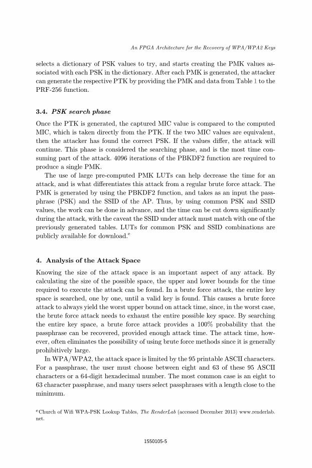
With this information, the attack space of WPA/WPA2 is calculated in Table 2.
This table shows that even for the best case, an eight-character password, the size of
the brute force attack space is still a large number. To demonstrate the total attack
time, consider an example where the attacker can generate and test 1,000 pass-
phrases per second. An attack would consequently take
time ¼ ð6:63� 1015Þ phrases � 1 s
1000 phrases� 1 year
31;536;000 s� 210;236 years: ð1Þ
This time complexity prohibits the e®ectiveness of a brute force attack on this space.
The brute force attack space, however, assumes that the user has selected a
random passphrase from the available character set. If the passphrase is not gener-
ated at random, it is possible to remove a large part of the attack space, e®ectively
lowering the attack time. There are several common ways to reduce the attack space,
but the dictionary attack is probably the most simple to implement.
The dictionary attack is e®ective by limiting the attack space to known words
from the dictionary of a given language: A list of names or common terms, for
example. The attacker can then compile a list of these possibilities, which provides a
much smaller attack space than the brute force method does. The trade-o® made
with this approach is a reduction of the probability of success, and depends upon the
selection of a dictionary. It also requires that the actual passphrase is present in the
attacker's dictionary.
To determine the attack space for the dictionary attack, the size of the dictionary
must ¯rst be determined. According to the Oxford Dictionariesf and Merriam-
Webster,g there are currently around 500,000 entries in the English dictionary.
However, a smaller dictionary is provided by most operating systems. At the time of
this writing, for example, 235,886 words were counted by the wc command on a Mac
OSX10:7:5 system. The time complexity to attempt each of these dictionaries, with
the same rate of 1000 passphrases/s, is 3.93 and 8.33min, respectively.
The table shows that the time complexity becomes much more manageable when
the attack space is limited by a dictionary. This comes at a cost of lower attack
success rates. The dictionary attack success rate can be improved by using programs
Table 2. Best and worst case brute force attack spaces.
Case ASCII character count Permutations Space size
Best case 8 958 6:63� 1015
Worst case 63 9563 3:95� 10124
fHow many words are there in the English language?Oxford Dictionaries (accessed December 2013) www.
oxforddictionaries.com.gHow many words are there in English? Merriam-Webster (accessed December 2013) www.merriam-webster.com.
T. Johnson et al.
1550105-6
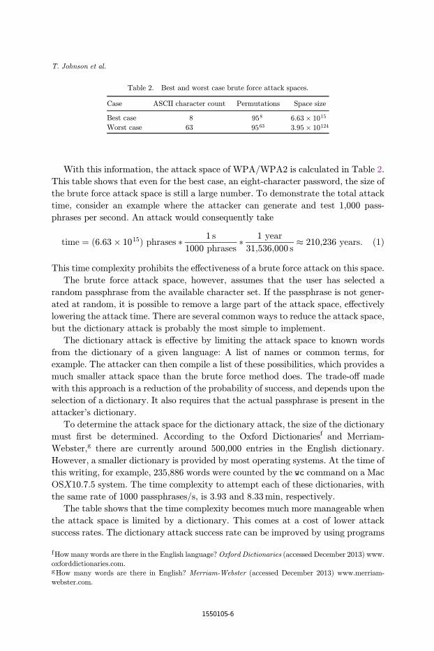
such as John The Ripper,h to alter each word in the dictionary to contain common
pre¯xes and post¯xes. For example, the common passphrase \password" would exist
in the dictionary. A common post¯x for this passphrase is \1," to yield \password1,"
which would not be in the English dictionary. John The Ripper will generate
attempts such as \password1," \password2," . . . ; for each entry in the dictionary.
Doing this, however, will again increase the time complexity of the attack. In
Table 3, it can be seen that the time complexity increases signi¯cantly as the number
of post¯x characters increases.
5. WPA Protocol Overview
This section describes the handshake protocol used in WPA, and then summarizes
the fundamental algorithms the protocol is built upon.
5.1. WPA four-way handshake
WPA depends upon a four-way handshake process to authenticate with a client to
the network. In WPA PSK mode, there are only two parties involved in the au-
thentication process: the Authenticator (AP) and the supplicant (mobile client).
Both parties must prove to each other that they know the PSK to ensure a secure
connection. It is important to note that the PSK is never sent between the supplicant
and authenticator, it is up to the user to program this key into each party. This is
also important because there is no secure channel of communication before the au-
thentication process has completed, so sharing the PSK would be done unencrypted,
and would therefore be easily discoverable by outside parties. The four-way process is
broken down into messages A–D in the following section. Figure 1 provides a dem-
onstration of this process.
hJohn the Ripper password cracker, Openwall (accessed December 2013) www.openwall.com/john.
Table 3. Time complexity of dictionary attack using John the Ripper,
assuming 1000 passphrases/s.
Con¯guration Example phrase Time (h)
Any dictionary wordþ 1 digit (1–9) word1 1.5
Any dictionary wordþ 2 digit (1–9) word12 13.5
Any dictionary wordþ 3 digit (1–9) word123 121.5
Any dictionary wordþ 4 digit (1–9) word1234 1093.5Any dictionary wordþ 5 digit (1–9) word12345 9841.5
Any dictionary wordþ 6 digit (1–9) word123456 88573.5
Any dictionary wordþ 7 digit (1–9) word1234567 797161.5Any dictionary wordþ 8 digit (1–9) word12345678 7174453.5
Any dictionary wordþ 9 digit (1–9) word123456789 64570081.5
An FPGA Architecture for the Recovery of WPA/WPA2 Keys
1550105-7
5.1.1. Message A Authenticator ! Supplicant
The ¯rst step is where the authenticator generates a nonce value. The nonce value is
a pseudorandom value generated by a publicly known and repeatable process. In a
perfect implementation, a nonce value would never be used more than once. Since
this property is not feasible, it is enough to provide a very high probabilistic guar-
antee that the value will not be chosen again. The pseudorandom value is generated
by the Pseudorandom Function 256, or PRF-256, as de¯ned by the WPA speci¯-
cation. The nonce value that the authenticator generates is denoted as the ANonce.
Upon generation of the ANonce, the authenticator sends a message to the supplicant
containing the ANonce value.
5.1.2. Message B Supplicant ! Authenticator
The supplicant then generates ANonce value using the same process as the au-
thenticator. This Nonce value is denoted as the SNonce. Upon the supplicant re-
ceiving Message A from the authenticator, the supplicant can generate the transient
key. This key is required to be generated by both parties, and allows each party to
verify that the other has the correct PSK. To generate the transient key, the sup-
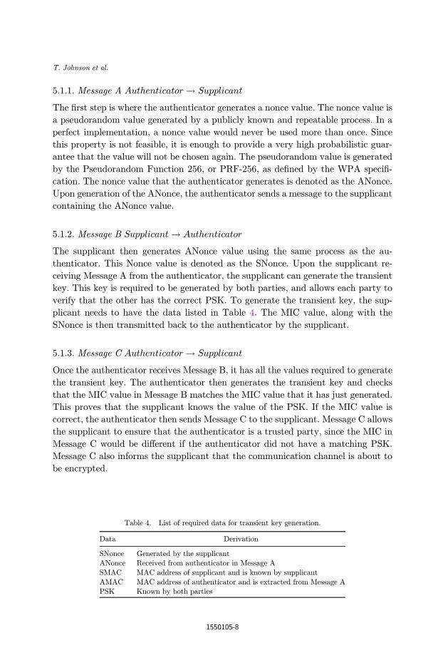
plicant needs to have the data listed in Table 4. The MIC value, along with the
SNonce is then transmitted back to the authenticator by the supplicant.
5.1.3. Message C Authenticator ! Supplicant
Once the authenticator receives Message B, it has all the values required to generate
the transient key. The authenticator then generates the transient key and checks
that the MIC value in Message B matches the MIC value that it has just generated.
This proves that the supplicant knows the value of the PSK. If the MIC value is
correct, the authenticator then sends Message C to the supplicant. Message C allows
the supplicant to ensure that the authenticator is a trusted party, since the MIC in
Message C would be di®erent if the authenticator did not have a matching PSK.
Message C also informs the supplicant that the communication channel is about to
be encrypted.
Table 4. List of required data for transient key generation.
Data Derivation
SNonce Generated by the supplicant
ANonce Received from authenticator in Message A
SMAC MAC address of supplicant and is known by supplicant
AMAC MAC address of authenticator and is extracted from Message APSK Known by both parties
T. Johnson et al.
1550105-8
5.1.4. Message D Supplicant ! Authenticator
The ¯nal part of the handshake allows the supplicant to acknowledge that the
authenticator is now going to use encryption for the communication. After the
supplicant transmits Message D, it will install the encryption keys on the channel.
After the authenticator receives Message D, it will also install the encryption keys.
After this point, all further unicast communication is protected by this encryption,
until the client disconnects from the AP.11
5.2. SHA-1
The SHA-1 is a secure one-way hashing function that is used in supporting the PSK
architecture of WPA/WPA2. It was developed by the National Security Agency
(NSA) and later published by the National Institute of Standards and Technology
(NIST). The SHA-1 is considered a secure hashing algorithm by the NIST, and has
been published as an acceptable hashing function for use in sensitive data by gov-
ernment agencies.i
The SHA-1 hashing algorithm is valid for messages with a size less than 264 bits,
operates on blocks of size 512 bits, uses a word size of 32 bits, and the resultant
message digest is 160 bits.
SHA-1 can be separated into two stages of processing. The ¯rst stage is the pre-
processing stage, where the message is manipulated in preparation of being hashed.
This involves padding the message and parsing the message into blocks. The second
stage is where the message is processed by the various logical functions for 80 rounds
to produce the hash value.
5.3. HMAC
Hash-based message authentication code (HMAC) provides a mechanism to calcu-
late a MAC using a cryptographic hashing function and a key. HMAC may use any
cryptographic hashing function for the underlying computation of the ¯nal MAC,
such as SHA-1 or MD5. The output size of the resulting MAC, and the cryptographic
strength of the HMAC, are dependent upon the underlying hashing algorithm.
WPA uses an HMAC-SHA1 implementation, where SHA-1 is chosen as the un-
derlying hashing algorithm. The resultant MAC is thus 160 bits in length. HMAC
iterates on two rounds of hashing, with certain logical operations performed on the
key and text between each round. The function de¯nition of HMAC is as follows:
HðK � opad;HðK � ipad; textÞÞ: ð2ÞHere, K is the key, opad and ipad are constants, text is the salt and H is the
underlying hashing algorithm. In round 1, the (text) is appended to the end of the
iFIPS PUB 180-4: Secure Hash Standard, U.S. government standard, National Institute of Standards andTechnology (2012).
An FPGA Architecture for the Recovery of WPA/WPA2 Keys
1550105-9
result ofK XOR ipad, and then hashed. Upon completion of the ¯rst hashing process,
the result of the hash is then appended to K XOR opad, and the resulting value is
hashed one ¯nal time to produce the ¯nal result.12
5.4. PBKDF2
WPA/WPA2 depends upon the PBKDF213 function to generate the PMK values.
The PBKDF2 can use any underlying pseudorandom function. However, the WPA/
WPA2 speci¯cation requires that HMAC-SHA1 is used for this random generator.
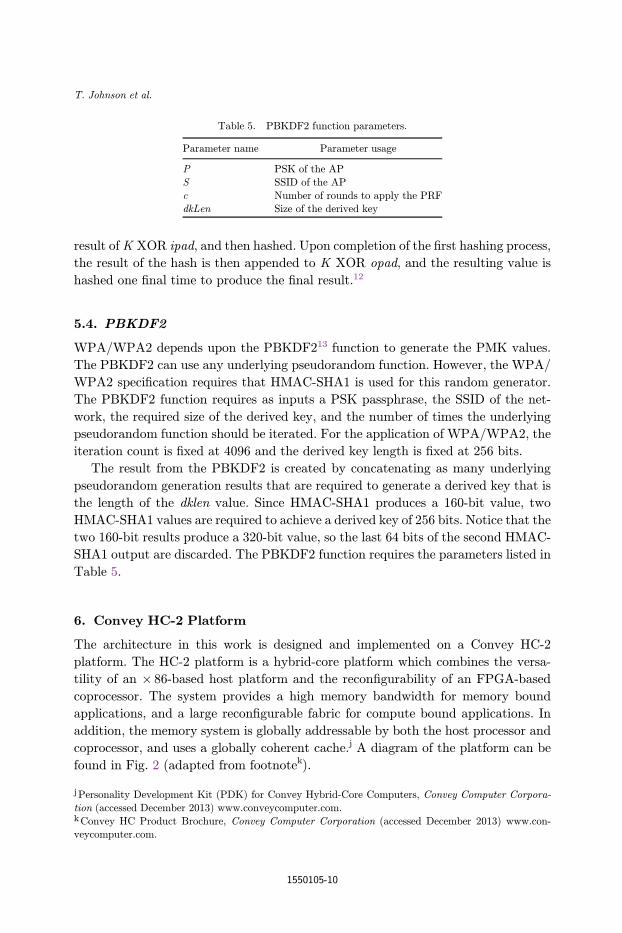
The PBKDF2 function requires as inputs a PSK passphrase, the SSID of the net-
work, the required size of the derived key, and the number of times the underlying
pseudorandom function should be iterated. For the application of WPA/WPA2, the
iteration count is ¯xed at 4096 and the derived key length is ¯xed at 256 bits.
The result from the PBKDF2 is created by concatenating as many underlying
pseudorandom generation results that are required to generate a derived key that is
the length of the dklen value. Since HMAC-SHA1 produces a 160-bit value, two
HMAC-SHA1 values are required to achieve a derived key of 256 bits. Notice that the
two 160-bit results produce a 320-bit value, so the last 64 bits of the second HMAC-
SHA1 output are discarded. The PBKDF2 function requires the parameters listed in
Table 5.
6. Convey HC-2 Platform
The architecture in this work is designed and implemented on a Convey HC-2
platform. The HC-2 platform is a hybrid-core platform which combines the versa-
tility of an � 86-based host platform and the recon¯gurability of an FPGA-based
coprocessor. The system provides a high memory bandwidth for memory bound
applications, and a large recon¯gurable fabric for compute bound applications. In
addition, the memory system is globally addressable by both the host processor and
coprocessor, and uses a globally coherent cache.j A diagram of the platform can be
found in Fig. 2 (adapted from footnotek).
Table 5. PBKDF2 function parameters.
Parameter name Parameter usage
P PSK of the AP
S SSID of the AP
c Number of rounds to apply the PRFdkLen Size of the derived key
jPersonality Development Kit (PDK) for Convey Hybrid-Core Computers, Convey Computer Corpora-
tion (accessed December 2013) www.conveycomputer.com.kConvey HC Product Brochure, Convey Computer Corporation (accessed December 2013) www.con-veycomputer.com.
T. Johnson et al.
1550105-10
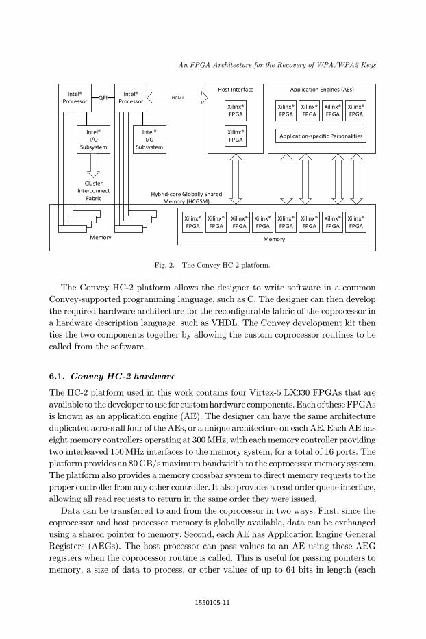
The Convey HC-2 platform allows the designer to write software in a common
Convey-supported programming language, such as C. The designer can then develop
the required hardware architecture for the recon¯gurable fabric of the coprocessor in
a hardware description language, such as VHDL. The Convey development kit then
ties the two components together by allowing the custom coprocessor routines to be
called from the software.
6.1. Convey HC-2 hardware
The HC-2 platform used in this work contains four Virtex-5 LX330 FPGAs that are
available to the developer touse for customhardware components.Eachof theseFPGAs
is known as an application engine (AE). The designer can have the same architecture
duplicated across all four of the AEs, or a unique architecture on each AE. EachAE has
eightmemory controllers operating at 300MHz, with eachmemory controller providing
two interleaved 150MHz interfaces to the memory system, for a total of 16 ports. The
platform provides an 80GB/smaximumbandwidth to the coprocessormemory system.
The platform also provides a memory crossbar system to direct memory requests to the
proper controller from any other controller. It also provides a read order queue interface,
allowing all read requests to return in the same order they were issued.
Data can be transferred to and from the coprocessor in two ways. First, since the
coprocessor and host processor memory is globally available, data can be exchanged
using a shared pointer to memory. Second, each AE has Application Engine General
Registers (AEGs). The host processor can pass values to an AE using these AEG
registers when the coprocessor routine is called. This is useful for passing pointers to
memory, a size of data to process, or other values of up to 64 bits in length (each
Fig. 2. The Convey HC-2 platform.
An FPGA Architecture for the Recovery of WPA/WPA2 Keys
1550105-11
AEG is a 64-bit register). If the coprocessor routine is expected to provide a return
value, the return value should be stored into the AEG speci¯ed as the return register.
The coprocessor can also store any 64-bit result into any other available AEG, and
then the host processor can access that AEG after the coprocessor routine has
completed. Generally, large data should be passed using the memory system, and
small data passed in an AEG.l ;m ;n ;o
6.1.1. Xilinx FPGAs
The main computational fabric of a Xilinx FPGA consists of con¯gurable logic
blocks (CLBs). Each CLB consists of two slices, which contain the following com-
ponents: Four function generators (six-input LUTs), four storage elements (°ip-
°ops), arithmetic logic gates, large multiplexers, and a fast carry look-ahead chain.
Additional on-chip resources include block RAMs and DSP48E slices. Each DSP slice
contains a 25� 18 bit multiplier, an adder, and an accumulator. The Virtex-5 chip
targeted in this work is the XC5VLX330T, which contains 51,840 slices and 192
DSP48E slices.p ;q
7. Our PMK Generation Architecture
The goal of our architecture is to accelerate the generation of WPA/WPA2 PMKs.
This process is compute bound, meaning the speed of the application is limited by the
number of processing resources available. To achieve the best performance in a
compute bound application, the recon¯gurable fabric provided by the HC-2 platform
will need to be fully and e±ciently utilized. An overview of the steps of the PMK
generation process is listed below.
(1) Read the next PSK to create the PMK.
(2) Request the next PSK using the memory interface.
(a) Wait for the memory request to complete before proceeding.
(3) Start computing the PBKDF2 of the SSID and PSK.
(a) Requires 4096 HMAC iterations.
(b) The HMAC process requires four SHA-1 iterations for this application.
(c) SHA-1 is an 80 round operation per 512 bits of input.
(4) Store the PMK to memory upon completion for later veri¯cation.
(5) Repeat this process from Step 1.
lConvey Computer Corp. Convey Personality Development Kit Reference Manual, ver. 5.2 (2012).mConvey Computer Corp. Convey Programmers' Guide, ver. 1.8 (2010).nConvey Computer Corp. Convey Reference Manual, ver. 2.0 (2009).oConvey PDK FPGA Design Practices, whitepaper, Convey Computer Corp. (accessed December 2013).pVirtex 5 Family Overview, datasheet, Xilinx, Inc. (2009).qXilinx, Inc. Virtex 5 FPGA User Guide (UG190), ver. 5.4 (2012).
T. Johnson et al.
1550105-12
As can be inferred from the above steps, the PBKDF2 calculations are where the
majority of the time is spent. This warrants an architecture that can provide as much
PBKDF2 computation resources as it can be ¯ted into the fabric, while allowing
enough space to include the control logic.
7.1. Software
The software that supports the architecture needs to prepare the coprocessor for the
custom instruction before the call can be made. The supporting software is written in
C++ and takes advantage of the Convey Development Kit. The software provides
con¯guration information for each of the four AEs on the coprocessor, and performs
validation of PMKs to ¯nd the correct passphrase.
The ¯rst responsibility of the software is to process the provided dictionary of
passphrases. This dictionary is a text ¯le, formatted with each line representing an
entry in the dictionary. The software veri¯es each passphrase, ensuring that the
passphrase meets length requirements and is a valid ASCII character. Each valid
passphrase is then moved to the coprocessor memory, starting at a base memory
location allocated for the dictionary.
Once each passphrase has been veri¯ed and loaded into coprocessor memory, the
software splits the dictionary into four blocks. This is done by dividing the size of the
dictionary by four, and assigning the remainder to the ¯rst AE. Memory o®sets into
the dictionary are then calculated, to provide hardware with the proper start loca-
tions. Memory for the PMK storage is allocated in the memory of the coprocessors, as
well. This storage is divided into four parts in the same manner as the dictionary
storage is divided.
After allocating the required memory, loading the dictionary, and calculating the
o®sets, the software is ready to call the custom coprocessor instruction. This is done
by using a function provided by the Convey platform. The function takes the fol-
lowing input parameters: A memory address to start reading the dictionary for each
AE, a PMK storage address to start storing the generated PMKs, the number of
passphrases each AE will process, the SSID, and the length of the SSID. This high-
level call is translated into an assembly function that the developer is responsible for
writing. Each parameter is transferred to a register in a soft processor on the co-
processor, and the assembly routine is called. This routine then moves data from the
registers in the soft processors into the AEG registers of each AE. After the para-
meters have been passed to each AE, the soft processor calls the coprocessor custom
instruction.
The software on the host processor then checks the PMK storage, and starts
searching for PMK matches as new PMKs become available. Initially, each location
of the PMK storage is zeroed out, so polling on a non-zero value will indicate to the
software when the next PMK is ready. This can be split into four separate threads,
one thread to check each of the four PMK addresses assigned to each AE.
An FPGA Architecture for the Recovery of WPA/WPA2 Keys
1550105-13

7.2. Hardware
In this section, the top-level view of the attacker architecture is introduced. Figure 3
shows the required parameters and outputs of the module. The parameters and
outputs for the attacker module are described in detail in Table 6. These parameters
are provided from the software and passed via the AEGs mentioned in Sec. 6.1. Each
of the four HC-2 AEs hosts an Attacker module. Figure 4 provides a high-level view
of the implemented Attacker architecture in which data °ows left to right.
The processing °ow can be divided into four stages: Passphrase/PMK synchro-
nization, passphrase fetch, PMK generation management and PMK storage
management.
7.2.1. Passphrase/PMK synchronization
First, the data starts at memory controller interfaces MCIF0 through MCIF7
as read operations. This data is passed through the hashing modules to produce
Fig. 3. Attacker input and output interface.
Table 6. Attacker input and output descriptions.
Port Description
Start Noti¯es that the software has ¯nished setup and the hardware should start the
attack.
Dictionary size Allows the attacker module to know how many elements it is responsible forprocessing, and allows it to know when it is complete.
Dictionary address Base address to the dictionary that has been moved to coprocessor memory. It
allows the attacker module to read the passphrases.
PMK store address Location that the attacker should start storing PMK results.SSID SSID of the network being attacked.
SSID length Length in bits of the SSID. The hardware needs to know this length to
properly pad the SHA-1 message blocks.
Complete count Output which allows the host processor to query the number of saved PMKs.Busy High during the attack phase and low otherwise.
T. Johnson et al.
1550105-14
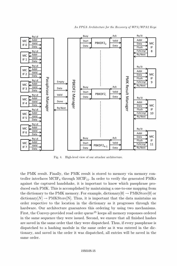
the PMK result. Finally, the PMK result is stored to memory via memory con-
troller interfaces MCIF8 through MCIF11. In order to verify the generated PMKs
against the captured handshake, it is important to know which passphrase pro-
duced each PMK. This is accomplished by maintaining a one-to-one mapping from
the dictionary to the PMK memory. For example, dictionary½0� ! PMKStore[0] or
dictionary½N � ! PMKStore[N]. Thus, it is important that the data maintains an
order respective to the location in the dictionary as it progresses through the
hardware. Our architecture guarantees this ordering by using two mechanisms.
First, the Convey-provided read order queue25 keeps all memory responses ordered
in the same sequence they were issued. Second, we ensure that all ¯nished hashes
are saved in the same order that they were dispatched. Thus, if every passphrase is
dispatched to a hashing module in the same order as it was entered in the dic-
tionary, and saved in the order it was dispatched, all entries will be saved in the
same order.
Fig. 4. High-level view of our attacker architecture.
An FPGA Architecture for the Recovery of WPA/WPA2 Keys
1550105-15
7.2.2. Passphrase fetch
The ¯rst part of the attack process requests the next passphrase from the dictionary.
This is controlled by the Passphrase Manager module, which can be seen in the
diagram. This module has access to eight memory controller interfaces. Each
memory controller has a read/write width of 64 bits. Since a passphrase will contain
a maximum of 512 bits, eight memory controllers will allow an entire passphrase to
be requested at once. The Passphrase Manager will make a request for the next
passphrase, and increment a counter that tracks the total number of read dictionary
entries. The Passphrase Manager contains eight FIFOs to handle the responses from
the memory controllers. By using the read order queue, all responses will be returned
in the same order they were requested. Thus, when all eight FIFOs are non-empty,
the data at the front of each FIFO can be pieced together in the proper order to form
the 512-bit passphrase. When a passphrase is ready, the empty signal is de-asserted,
and the PBKDF2 Manager will be able to start issuing passphrases to available
PBKDF2 modules. The Passphrase Manager will continue to request the next
passphrase until the FIFOs become full, or the read count is equal to the size of the
dictionary.
7.2.3. PMK generation management
The second part of the attack is where the hashing takes place. The PBKDF2
Manager is responsible for dispatching each passphrase to an available PBKDF2
module to generate the PMKs. The module dispatches each passphrase in a round
robin order to each hashing module. This allows the architecture to maintain the
correct order. Each PBKDF2 module has a busy °ag, which allows the PBKDF2
Manager to verify if a module can accept a new passphrase. When the next hashing
module in the schedule indicates it is not busy, the PBKDF2 Manager dispatches the
passphrase and asserts the start signal for this module. The PBKDF2 Manager will
then proceed to the next available passphrase and hashing module, until all modules
indicate they are currently busy. Each hashing module will ¯nish in the same order
that they were started, since the runtime to generate each PMK is constant.
7.2.4. PMK storage management
Finally, the Result Manager is used to store each PMK to the memory of the co-
processor using the memory controller interfaces MCIF8 through MCIF11. As each
PBKDF2 hashing module completes and drives the valid signal high, the Result
Manager will store the result in a round robin manner. The round robin operation
allows the architecture to keep the required ordering, as previously mentioned. The
Result Manager then increments the stored PMK count and sends an acknowledg-
ment to the ¯nished hashing module. The acknowledgment is used to inform the
hashing module that it may overwrite the result register, if needed. The hashing
module will still be able to proceed with hashing the next passphrase, but it is
T. Johnson et al.
1550105-16
important that the hash result and valid signal remain unchanged until the ac-
knowledgment is provided. This is because any of the memory controller interfaces
used for storing the results may non-deterministically request a stall for all writes to
that interface. A stall will also cause the Result Manager to halt its round robin
operations. Thus, if the hashing module modi¯ed the valid or result signals before the
acknowledgement occurs, the PMK would be lost. In general, a memory interface
stall will only last for a fraction of the time required to generate the next PMK, so a
memory stall should not cause many stalls of the hashing process, which would
degrade the performance.
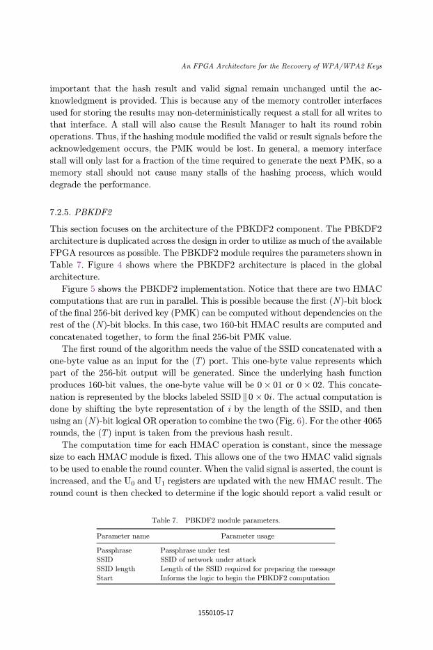
7.2.5. PBKDF2
This section focuses on the architecture of the PBKDF2 component. The PBKDF2
architecture is duplicated across the design in order to utilize as much of the available
FPGA resources as possible. The PBKDF2 module requires the parameters shown in
Table 7. Figure 4 shows where the PBKDF2 architecture is placed in the global
architecture.
Figure 5 shows the PBKDF2 implementation. Notice that there are two HMAC
computations that are run in parallel. This is possible because the ¯rst (N)-bit block
of the ¯nal 256-bit derived key (PMK) can be computed without dependencies on the
rest of the (N)-bit blocks. In this case, two 160-bit HMAC results are computed and
concatenated together, to form the ¯nal 256-bit PMK value.
The ¯rst round of the algorithm needs the value of the SSID concatenated with a
one-byte value as an input for the (T) port. This one-byte value represents which
part of the 256-bit output will be generated. Since the underlying hash function
produces 160-bit values, the one-byte value will be 0� 01 or 0� 02. This concate-
nation is represented by the blocks labeled SSID jj 0� 0i. The actual computation is
done by shifting the byte representation of i by the length of the SSID, and then
using an (N )-bit logical OR operation to combine the two (Fig. 6). For the other 4065
rounds, the (T) input is taken from the previous hash result.
The computation time for each HMAC operation is constant, since the message
size to each HMAC module is ¯xed. This allows one of the two HMAC valid signals
to be used to enable the round counter. When the valid signal is asserted, the count is
increased, and the U0 and U1 registers are updated with the new HMAC result. The
round count is then checked to determine if the logic should report a valid result or
Table 7. PBKDF2 module parameters.
Parameter name Parameter usage
Passphrase Passphrase under test
SSID SSID of network under attack
SSID length Length of the SSID required for preparing the messageStart Informs the logic to begin the PBKDF2 computation
An FPGA Architecture for the Recovery of WPA/WPA2 Keys
1550105-17

continue with the hashing process. If all rounds are completed, the entire 160 bits of
U0 and the top 96 bits of U1 are concatenated together to form the ¯nal result, and
the valid signal is then driven high.
7.2.6. HMAC
This section introduces the logic for the HMAC computation (Sec. 5.3). The HMAC
module relies on SHA-1 as the underlying hashing algorithm. The attack will only
ever require a maximum of 841 bits to be hashed for any SHA-1 message. This value
derives from the fact that the input to the HMAC function will either be a 160-bit
Fig. 6. Round 1T generation using \test" as the SSID.
Fig. 5. The PBKDF2 module.
T. Johnson et al.
1550105-18
HMAC result concatenated with a 512-bit value (iPad/oPad XOR passphrase), or it
will be a 512-bit value (iPad/oPad XOR passphrase) concatenated with the SSID
and the one byte representation from the PBKDF2 requirements. Both cases will also
include a binary \1" bit appended to the end of the message data, and require the last
64 bits of the message to contain the entire length of the message. This bit distri-
bution can be found in Table 8.
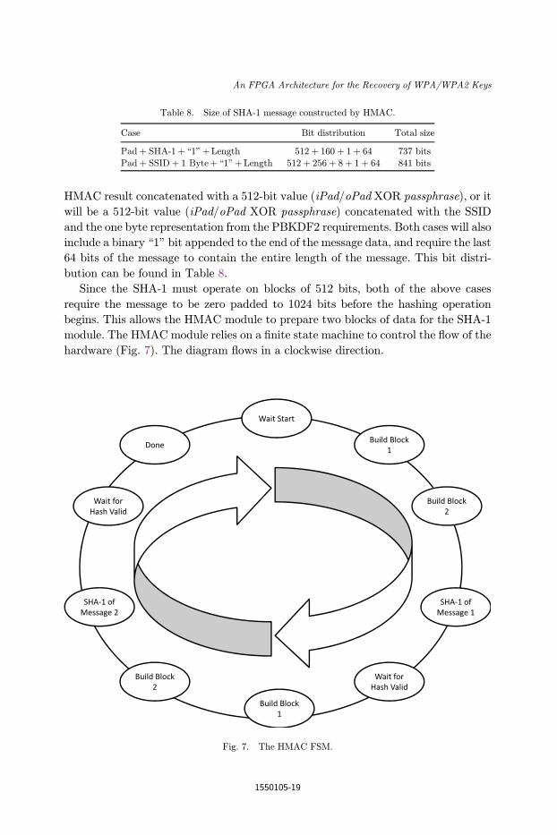
Since the SHA-1 must operate on blocks of 512 bits, both of the above cases
require the message to be zero padded to 1024 bits before the hashing operation
begins. This allows the HMAC module to prepare two blocks of data for the SHA-1
module. The HMAC module relies on a ¯nite state machine to control the °ow of the
hardware (Fig. 7). The diagram °ows in a clockwise direction.
Table 8. Size of SHA-1 message constructed by HMAC.
Case Bit distribution Total size
Padþ SHA-1þ \1"þLength 512þ 160þ 1þ 64 737 bits
Padþ SSIDþ 1 Byteþ \1"þLength 512þ 256þ 8þ 1þ 64 841 bits
Fig. 7. The HMAC FSM.
An FPGA Architecture for the Recovery of WPA/WPA2 Keys
1550105-19
The ¯rst block of the ¯rst message is created from the operation of iPad� k.
The second block of the ¯rst message is assembled by ¯rst inserting the SSID into
the upper bits of the assembly register. A binary \1" is then shifted right by the
length of the SSID and combined into the assembly register using a logical OR
operation. Finally, the lower 64 bits are assigned the value of the total length of
the message. The message length is computed by adding the 512 bits of the iPad�k operation to the length of the SSID. The bits added to the message block by the
concatenation of the appended binary \1" and the 64-bit message length are not
considered part of the original message, and thus not included. During the second
round, it is easier to generate the two blocks, as the sizes of these blocks are ¯xed.
The ¯rst block is the 512-bit result of oPad� k. The second block is the 160-bit
Fig. 8. Top-level view of the SHA-1 component.
T. Johnson et al.
1550105-20

SHA-1 result from the ¯rst round appended with the binary \1" and the lower 64
bits representing the length. Thus, the length will always be 672 bits, derived from
512 bitsþ 160 bits, so no shifting or addition operations are required to assemble
this block.
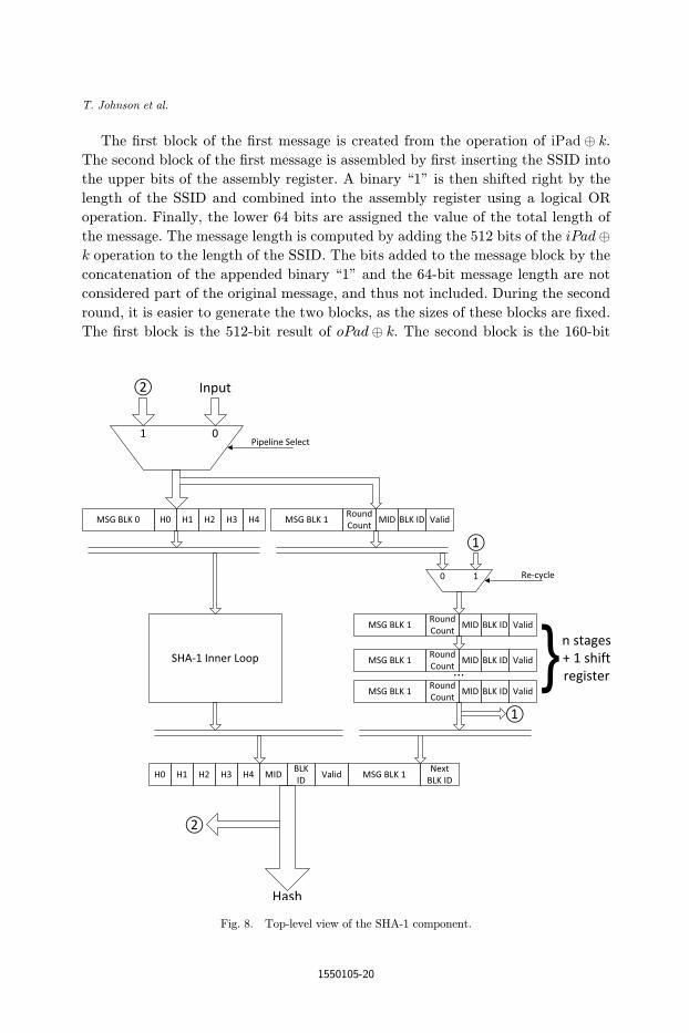
7.2.7. SHA-1
The SHA-1 implementation is pipelined to allow multiple messages to be hashed
simultaneously. Due to the iterative nature of the SHA-1 algorithm, it is impossible
to parallelize the hashing of a single message, but with a pipelined implementation,
up to 80 di®erent messages can be hashed at once, depending on how many iterations
of the inner loop are unrolled. As shown in Fig. 8, the top level of the SHA-1 design
contains shift registers and multiplexers. The ¯rst set of registers captures the input
signals only if no valid message in the ¯nal register has another block to hash. Since
this particular application only requires two blocks to be hashed for any message, we
optimize the design to assume every message will have two blocks to hash. This
simpli¯es the shift registers and the control logic, since a message will only need to go
through the entire pipeline twice.
At the same time, a message is launched into the SHA-1 inner loop module, the
next block is loaded into the shift register containing as many registers as the number
of iterations, the inner loop has been unrolled. If the number of loop iterations is less
than 80, then the message will need to be re-cycled through the pipeline. For this
reason, we restrict the number of unrolled iterations to be a factor of 80. Once a
message has been hashed entirely, it is output and the valid signal is asserted. If the
pipeline was previously at maximum capacity, then a new message is allowed into the
pipeline. Messages will be output in the same order they were input.
Fig. 9. The SHA-1 inner loop pipeline stage.
An FPGA Architecture for the Recovery of WPA/WPA2 Keys
1550105-21
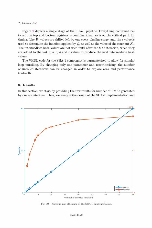
Figure 9 depicts a single stage of the SHA-1 pipeline. Everything contained be-
tween the top and bottom registers is combinational, so is on the critical path for
timing. The W values are shifted left by one every pipeline stage, and the t value is
used to determine the function applied by ft, as well as the value of the constant Kt.
The intermediate hash values are not used until after the 80th iteration, when they
are added to the last a, b, c, d and e values to produce the next intermediate hash
values.
The VHDL code for the SHA-1 component is parameterized to allow for simpler
loop unrolling. By changing only one parameter and resynthesizing, the number
of unrolled iterations can be changed in order to explore area and performance
trade-o®s.
8. Results
In this section, we start by providing the raw results for number of PMKs generated
by our architecture. Then, we analyze the design of the SHA-1 implementation and
Number of unrolled iterations0
Spe
edup
0
20
4010 -3
0
1
2
SpeedupEfficiency
0 30 10 2 0 40 50 60 70 8
Fig. 10. Speedup and e±ciency of the SHA-1 implementation.
T. Johnson et al.
1550105-22
its impact on the design as a whole. Lastly, we provide analysis of our design against
other implementations.
The number of PMKs that can be generated per second directly depends upon
how long it takes to compute a PBKDF2 result, which depends upon the speed of the
HMAC computations, which, in turn, depends upon the computation time for a
SHA-1 hash. Our design parallelizes the PBKDF2 function by computing the two
blocks of the derived key in parallel, by instantiating two HMAC components and
computing one block of the derived key on each of them. Each HMAC instance
requires two SHA-1 hashes, where the second depends on the result of the ¯rst. For a
SHA-1 implementation that takes 82 cycles and is purely sequential (that is, one call
at a time can use the component), the number of cycles to generate one PMK is:
8192 iterations
derived key� 2 SHA� 1 hashes
HMAC call� 164 cycles
message¼ 2;686;976 cycles: ð3Þ
For a parallelized PBKDF2 function (still assuming hashing one message at a time),
this number is divided by two to obtain 1,343,488 cycles per PMK.
Number of unrolled iterations
0
Per
cent
age
utili
zed
0
5
10
15
20
25
30
35
40
45
Slice RegistersSlice LUTsSlices Occupied
0 2 0 4 0 70 1 0 3 0 50 6 0 8
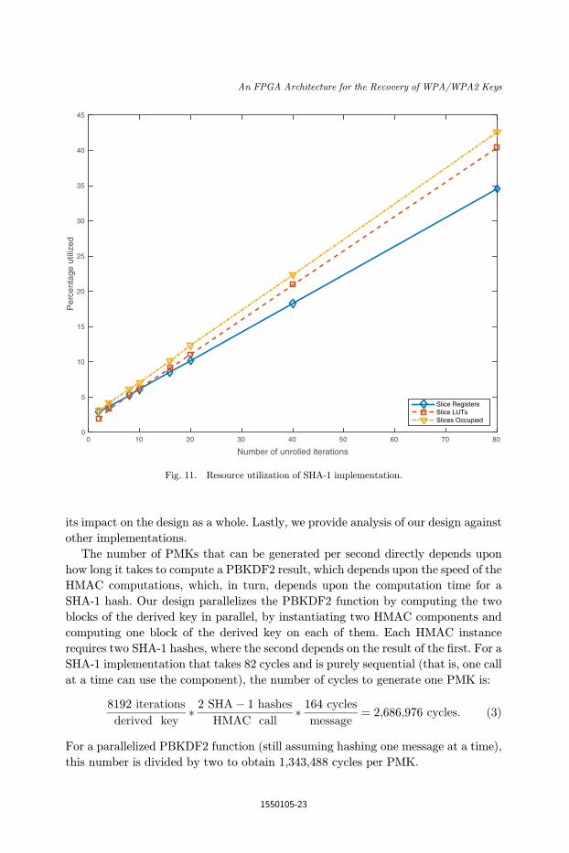
Fig. 11. Resource utilization of SHA-1 implementation.
An FPGA Architecture for the Recovery of WPA/WPA2 Keys
1550105-23
Now, assume the SHA-1 implementation is unrolled by n stages. Then the number
of PMKs generated per cycle can be obtained by the following equation:
n stages
21;343;488 cyclesþ n stages
: ð4Þ
The performance baseline for this implementation is the number of cycles for gen-
erating two PMKs in parallel. Figure 10 shows the speedup from increasing the
number of unrolled iterations (n pipeline stages). Also shown is the e±ciency, in
PMKs per slice, for each number of pipeline stages. The plot shows that, as speedup
increases linearly, the e±ciency (PMKs/slice) increases approximately logarithmi-
cally. The maximum obtainable speedup of this design is 40�, if the SHA-1 loop is
fully unrolled. The resource utilizations for a given number of unrolled iterations are
shown in Fig. 11. As can be seen, the relationship between the number of unrolled
iterations and resource usage is approximately linear.
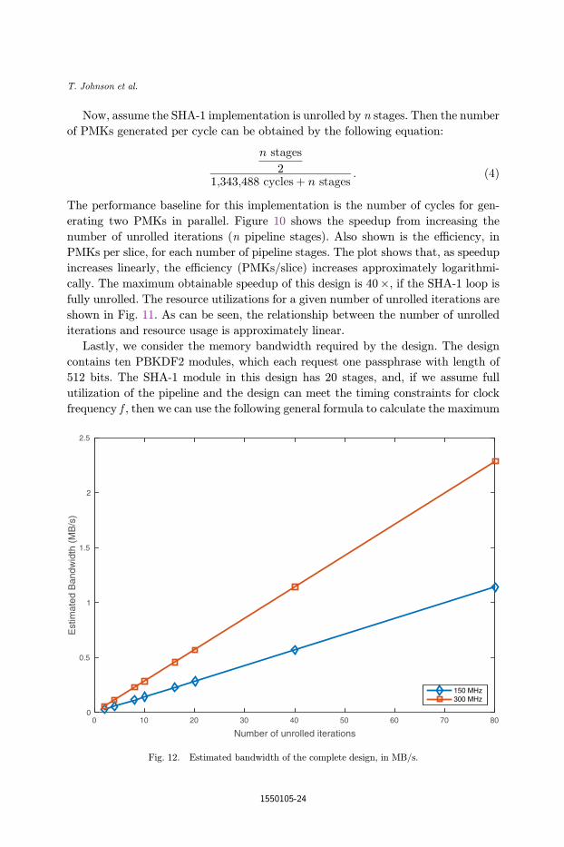
Lastly, we consider the memory bandwidth required by the design. The design
contains ten PBKDF2 modules, which each request one passphrase with length of
512 bits. The SHA-1 module in this design has 20 stages, and, if we assume full
utilization of the pipeline and the design can meet the timing constraints for clock
frequency f , then we can use the following general formula to calculate the maximum
Number of unrolled iterations
0 40 1 0 3 0 50 60 70 2 0 80
Est
imat
ed B
andw
idth
(M
B/s
)
0
0.5
1
1.5
2
2.5
150 MHz300 MHz
Fig. 12. Estimated bandwidth of the complete design, in MB/s.
T. Johnson et al.
1550105-24
bandwidth required:
n stages
2� 512 bits
1 request� 1 request
1;343;488 cycles� f cycles
1 s� 1 Byte
8 bits¼ BW
Bytes
s: ð5Þ
To ¯nd the bandwidth of the design using all AEs, the above value is multiplied by
four (the number of AEs in our target platform). As Fig. 12 shows, at the maximum
frequency supported by the platform (note, this is not necessarily supported by our
design), the bandwidth is only about 2.3MB/s, which is considerably less than the
80GB/s maximum platform bandwidth.
Table 9 shows the impact loop unrolling has on the rate PMKs are generated with
our design (using one AE). The PMKs/cycle value is normalized to the minimum
number of unrolled iterations, which is two. Table 10 compares our design with other
available implementations. As can be seen, our design outperforms the Pyrit10 CPU
implementation, and the Open Ciphers Project11 FPGA implementation, but is
signi¯cantly outperformed by the Pyrit GPU implementations.
9. Conclusion
This work introduced an expandable architecture targeted for an FPGA-based
platform, with the purpose of recovering WPA/WPA2 passphrases. We reviewed the
dictionary-based attack to recover the passphrase, showed an analysis of the attack
space, introduced our architecture, and ¯nally analyzed the performance of the
system. The results show the design is scalable and could compete with other
implementations, given enough compute fabric. The analysis also showed that the
maximum achievable speedup of the design with an optimized SHA-1 core is
40� over an unoptimized SHA-1 implementation.
Table 10. Comparison againstother implementations.
Implementation PMK/s
Our work 8931
Pyrit on CPU 1300Pyrit on 1�GPU 19,500
Pyrit on 4�GPU 89,000
OpenCiphers 1000
Table 9. Loop unrolling performance.
Unrolled iterations PMKs/cycle (normalized) Resource utilization (%)
2 1 3.07
20 10 12.31
40 20 22.3580 40 42.55
An FPGA Architecture for the Recovery of WPA/WPA2 Keys
1550105-25
References
1. G. Lehembre, Wi-Fi security-WEP, WPA, and WPA2, Hakin9 Magaz. 14 (2005) 2–15.2. F. Sheldon, J. M. Weber, S.-M. Yoo and W. D. Pan, The insecurity of wireless networks,
IEEE Security Privacy 10 (2012) 54–61.3. E. Tews and M. Beck, Practical attacks against WEP and WPA, Proc. 2nd ACM Conf.
Wireless Network Security, Zurich, Switzerland (2009), pp. 79–86.4. T. Ohigashi and M. Morii, A practical message falsi¯cation attack on WPA, Proc. Joint
Workshop on Information Security, Cryptography and Information Security Conf. (2009).5. F. M. Halvorsen and O. Haugen, Cryptanalysis of IEEE 802.11i TKIP, M.Sc. thesis,
Norwegian University of Science and Technology (2009).6. J. Wright, cowpatty, Will Hack for SUSHI (accessed December 2013) www.will-
hackforsushi.com.7. D. Hulton, The OpenCiphers Project, OpenCiphers (accessed December 2013) open-
ciphers.sourceforge.net/oc.8. G. S. Athanasiou, G. Theodoridis, C. E. Goutis, H. E. Michail and T. Kasparis, A
systematic °ow for developing totally self-checking architectures for SHA-1 and SHA-2cryptographic hash families, J. Circuits Syst. Comput. 22 (2013) 1–46.
9. Y. K. Lee, H. Chan and L. Verbauwhede, Throughput optimized SHA-1 architectureusing unfolding transformation, Int. Conf. Application-Speci¯c Systems, Architectures,and Processors (2006), pp. 354–359.
10. A. Satoh and T. Inoue, ASIC-hardware-focused comparison for hash functions MD5,RIPEMD-160, and SHS, Integration 40 (2007) 3–10.
11. J. Edney and W. A. Arbaugh, Real 802.11 Security (Addison Wesley, Reading, 2003).12. H. Krawczyk, M. Bellare and R. Canetti, HMAC: Keyed-Hashing for Message Authen-
tication, RFC 2104 (Informational) (1997).13. B. Kaliski, PKCS #5: Password-Based Cryptography Speci¯cation Version 2.0, RFC
2898 (Informational) (2000).
T. Johnson et al.
1550105-26