An Expert System for Safety Instrumented System in ...
64
An Expert System for Safety Instrumented System in petroleum industry By Yi Xiong Dawei Zhu Thesis submitted in Partial Fulfillment of the Requirements for the Degree Master of Technology in Information and Communication Technology Faculty of Engineering and Science University of Agder Grimstad May 2010
Transcript of An Expert System for Safety Instrumented System in ...

An Expert System for Safety Instrumented System in petroleum
industry
By
Yi Xiong
Dawei Zhu
Thesis submitted in Partial Fulfillment of the
Requirements for the Degree Master of Technology in
Information and Communication Technology
Faculty of Engineering and Science
University of Agder
Grimstad
May 2010

Abstract
The expert system technology has been developed since 1960s and now it has proven to be a useful and effective tool in many areas. It helps shorten the time required to accomplish a certain job and relieve the workload for human staves by implement the task automatically. This master thesis gives general introduction about the expert system and the technologies involved with it. We also discussed the framework of the expert system and how it will interact with the existing cause and effect matrix. The thesis describes a way of implementing automatic textual verification and the possibility of automatic information extraction in the designing process of safety instrumented systems. We use the Protégé application [*] to make models for the Cause and Effect Matrix and use XMLUnit to implement the comparison between two files of interest.

Preface
This thesis is proposed by Origo Engineering AS. First of all, we would like to thank for the guidance of our supervisor Trond Friisø who has helped us to comprehend the concept of the problem at hand and provide constant assistant for us. And we would also like to thank Vladimir A Oleshchuk for the high level guidance. He gave us a direction toward which we build our project and valuable suggestions on thesis writing. Grimstad, May 2009 Dawei Zhu, Yi Xiong

Table of contents
Abstract ....................................................................................................................... 2 Preface ........................................................................................................................ 3 Table of contents ......................................................................................................... 4 List of figures ............................................................................................................... 5 List of tables ................................................................................................................ 6 1. Introduction .......................................................................................................... 7
1.1 Background .................................................................................................... 7 1.2 First glance at Expert system ......................................................................... 7 1.4 Report outline ................................................................................................. 8
2. Problem description ................................................................................................ 9 2.1 Problem statement ......................................................................................... 9 2.2 problem delimitations: .................................................................................. 12
2.2.1 Safety Instrumented system .............................................................. 12 2.2.2 Introduction of Expert system ............................................................ 14
2.2.3 Automatic Information extraction ............................................................... 19 2.3 Use Cases and System Analysis ................................................................. 19
2.3.1 Use Case ........................................................................................... 19 2.4.2 System Structure and components .................................................... 21
3. Natural language processing ................................................................................ 23 3.1 Information Extraction .............................................................................. 24 3.2 Example of IE ............................................................................................... 25 3.3 Methods of IE ............................................................................................... 25 3.3 XML and Information Extraction ............................................................... 26 3.4 Limitations of Information extraction system ............................................ 26
4. Standardizing format ............................................................................................. 27 4.1 XML.............................................................................................................. 27 4.2 RDF.............................................................................................................. 28 4.3 XML vs RDF ................................................................................................. 31
4.3.1. Simplicity ........................................................................................... 31 4.3.2. Tree and graph structure for relation and query ............................... 31 4.3.3. Exchange of data .............................................................................. 33
5. Ontologies and applications .................................................................................. 36 5.1 Ontology introduction ................................................................................... 36
5.1.1 Original meaning of ontologies .......................................................... 36 5.1.2 Ontologies in computer science ......................................................... 36 5.1.3 Component of ontologies ................................................................... 37 5.1.4 Ontology engineering ......................................................................... 38
5.2 Ontology language(OWL) ............................................................................ 38 5.2.1 Ontology language ............................................................................. 38 5.2.2 Status of ontology in the project ........................................................ 39 5.2.3 OWL and its sub-languages ............................................................... 40

5.2.4 OWL-DL with its syntax ...................................................................... 41 5.3 Protégé and FaCT++--implementation and reasoning tools ........................ 43
5.3.1 Protégé and its structures .................................................................. 43 5.3.2 Reasons for choosing Protégé .......................................................... 46 5.3.3 Protégé with OWL plug-in .................................................................. 47 5.3.4 FaCT++--analyzing and reasoning .................................................... 48
6. Verification implementation ................................................................................... 50 6.1 verification process ...................................................................................... 50
6.1.2 Identical elements recognition ........................................................... 51 6.1.3 Comparison between elements in different order .............................. 52 6.1.4 Ignore the comments ......................................................................... 53 6.1.5 Ignore the extra space in elements .................................................... 55 6.1.6 Identify the missing element .............................................................. 56
6.2 Limitations of this verification process ......................................................... 58 7. Discussion ............................................................................................................. 60 8. Conclusion and future work ................................................................................... 61
8.1 Conclusion ................................................................................................... 61 Future work ........................................................................................................ 61
Reference.................................................................................................................. 63
List of figures
Figure 1 Cause and Effect Matrix------------------------------------------------------------5 Figure 2 Interface of Cause and Effect editor---------------------------------------------11 Figure 3 basic SIS layout-----------------------------------------------------------------------12 Figure 4 SIS safety life-cycle phases--------------------------------------------------------14 Figure 5 Expert system structure-------------------------------------------------------------15 Figure 6 Use case of the expert system-----------------------------------------------------20 Figure 7 System structure of the Expert system-------------------------------------------21 Figure 8 Structure of Linguistics ---------------------------------------------------------------24 Figure 9 Example of ontology structure-------------------------------------------------------38 Figure10. Status of ontologies in this project------------------------------------------------39 Figure11. Example of Protégé-OWL syntax--------------------------------------------------44 Figure12. Protégé class hierarchy--------------------------------------------------------------45 Figure13. Protégé subordinate functions------------------------------------------------------46 Figure14. Protégé with OWL plug-in-------------------------------------------------------------47 Figure15. Class structure after reasoning------------------------------------------------------48 Figure 16 Standardization of two files in different forms-----------------------------------49

List of tables
Table 1 Comparison between Programs and Expert systems---------------------16 Table 2 OWL-DL descriptions, data ranges, individuals and data values--------42 Table3. OWL-DL axioms and facts--------------------------------------------------------43 Table 4 Safety specifications------------------------------------------------58

1. Introduction
Chapter 1.1 introduces the background of the project and the specific field that we are about to dive in. Chapter 1.2 describes the previous work of automatic transform of data types. By introducing the current status of the process of producing SIS specification, we will see the benefit of applying automatic implementation and the possible improvement resulted from the automation. Chapter 1.3 gives the layout of the following chapters of this project.
1.1 Background
In an increasingly complex industrial environment with multidisciplinary factors, which work as interactive constituents within a system, any slight mistake might result in severe consequences such as conflagration, toxic gas leak or abnormal pressure level that will cost the company huge amount of money, in the worst cases lives could be lost. Thus it is obviously necessary to deploy a robust and reliable safety system to protect the asset from possible hazardous event. Before we make plans to build this safety system, the first thing that has to be done is to list all the regulations and policy into an official document, upon which the future system will be built. Judging by the scale of the industry, building such a system wouldn’t be easy and it would take lots of manpower and time to finish building a thorough and detailed document. Once the document has been formalized and produced, before building the safety instrumented system on the basis of the document, it is necessary to analyze the whole document to check if there is anything wrong or missing, since if the construction went wrong from the start, it will result in huge amount of financial loss of the customer and most likely the construction has to be reset and restarted all over again. Thus it is a common practice to let an experienced engineer to manually construct and verify the documents, likewise this could take lots of time and may not be accurate as required.
1.2 First glance at Expert system
The first expert system was developed in 1965 by Edward Feigenbaum and Joshua Lederberg of Stanford University in California, U.S. Dendral. It was firstly designed to help the chemists find unknown chemical compounds. Since then the expert system had been evloved through three stages and scientists are now working on the fourth generation. Nowadays expert systems are deployed in various areas such as chemistry, biology,

medical science, etc. The applications could be used to make financial decisions, perform diagnostic functions for patients, and many other tasks that normally requires human expert.
1.4 Report outline
The thesis will be organized as following: Chapter 2 describes the problem with scenarios as examples. Chapter 3 gives introduction of the natural language processing. Chapter 4 shows the two choices of ontology. Chapter 6 shows the prototype implementing the verification process. Chapter 7 discusses the possibility of fully automatic application in the future. Chapter 8 concludes the thesis.

2. Problem description
Section 2.1 gives the current status regarding the problem in Origo Engineering AS and the final goal we want to achieve. Section 2.2 analyzes the problem from different angle, and the goal of the expert system.
2.1 Problem statement
Origo engineering AS devote to provide reliable safety solutions for their customers. Their product could be implemented in Offshore Drilling, Offshore Production, FPSO, Petrochemical onshore industry (Refineries), onshore process industry (focus on Energy intensive processes), which are all safety-sensitive industries, a common way of provide safety solution is to design and implement a safety instrumented system. “A Safety Instrumented System (SIS) is a form of process control usually implemented in industrial processes, such as those of a factory or an oil refinery. The SIS performs specified functions to achieve or maintain a safe state of the process when unacceptable or dangerous process conditions are detected.” [1] It is composed of logic solvers, sensors and control elements and it implements one or more Safety Instrumented Functions to bring the process to a safety state if the current situation requires safety measures. Implementing SIS in the process industry for precaution reason is quite crucial and in order to fulfill the requirement of designing such an SIS, safety requirement specification (SRS) was introduced. SRS is used to specify all the requirements of safety instrumented systems that need to be fulfilled throughout the safety system building process. Origo Engineering has already developed a prototype of Cause and Effect editor, which allows users to record the information described in the document and rearrange them in a structured form. The left hand side is the causal event such as “gas detection”, “fire detection” and voting value such as “1ooN” or “2ooN”; the upper part of the matrix is the corresponding “effect” that describes the action taken to bring the faulty system state back to normal state, such as “initiate ESD”, “sounding alarm and start sprinkler”. Steps of the CEM working process are described below: 1. First the template document describing the list of causes and effects is imported
into the editor, usually in the excel form. However, a template actually refers to two files, an excel sheet with formatting but no data and a file describing the locations

of interest in the sheet, this form of separation is very beneficial for the modification of data in the input document and also the excel export. After cause and effect data have been imported to the editor, a sheet of matrix linking them is formed as the preconditions for dealing with the control logic. It should also be worth noting that in this step the causes would be well-classified according to incident types for easier fill-in process of logic in the later process.
2. Next step would be the defining of logic rules for this CEM sheet, which are corresponding linking between possible incidents and coping measures., the logic rules also have classifications describing sorts of control measures as different signs in the CEM shows. Currently this step is managed manually by experience engineers, an example of the CEM sheet is illustrated in figure with the rows as causes and the columns as effects.
Figure 1 Cause and Effect Matrix
3. On the other hand, general rules related to the specific system environments and
causing incidents are extracted from text documents describing requirements defined in standards of all kinds, including general international and national regulations, and principles oil companies have set up. The resulted document would be in a form that could be handled by the CEM editor showing different types of requirements that the logic rules in the CEM have to comply with, an example is shown in figure:

Figure 2 Interface of Cause and Effect editor
4. Now that CEM sheet and rule documents have been generated, the last step
would be the verification process, that is, to check if the logic rules in the CEM sheet satisfy all the requirements listed in the general rule text. The expected result would be a confirmation indication if there’s no discrepancy, or else a warning figuring out at which point inconsistency exists, which should be illustrated in a way for easy check and change.
Now we already have a prototype of Cause & Effect editor, which is used for extracting the clauses from the document and reorganize them into a systematic way. Currently the designing specifications and verification are processed manually by experienced engineers, they will examine each of the clauses in the document and fill them in the cause and effect matrix (CEM). After that they will also verify that everything in the document is consistent with the generated CEM. This is the traditional and reliable method of verification for the moment, yet it seems to be more and more inefficient, because nowadays the industry often involves multidisciplinary knowledge and the amount of information in instruction manuscript and specification increase so fast that manual verification gradually becomes error-prone and sluggish. The main focus of the project is to make improvements to the current process of designing such a SIS in the process industries. By introducing semantic and ontology technology into the process, engineers could be relieved from the tedious, error-prone work of checking and the possibility of automatically retrieve information from a textual document doesn’t seem so unrealistic.

2.2 problem delimitations:
2.2.1 Safety Instrumented system
It is a known fact that all systems, more or less, are subject to potential accident or malfunction. There are too many factors involved that could influence the operation process of the system and absolute safety simply does not exist, which is why SIS has been introduced. By employing the SIS, we could reduce the risk level to an expected, acceptable level, often been referred to as “as low as reasonably practicable” (ALARP). A SIS consists of the following parts, and the main structure of the system is shown in figure 1 below:
1. Sensors used for detection; 2. Signal input processor; 3. Logic solver; 4. Signal output processor; 5. Switch apparatus used for controlling device
Figure 3 basic SIS layout To properly design a safety instrumented system we have to list all the requirement of such a system in an official form, which is referred to as safety requirement specifications. The exact definition of safety requirement specification is given by the standard IEC 61511:

“Safety requirement specification is a specification that contains all the requirements of the safety instrumented functions that have to be performed by the safety instrumented systems.” [2] The requirements need to be planned before designing the safety system, as we can see from the next figure which shows the general steps of building a SIS, the SRS is generated in the third step after hazard assessment and allocation of the safety functions. This safety life cycle was proposed by IEC 61511-1.

Figure 4 SIS safety life-cycle phases.1
The internationally accepted IEC 61508 and IEC 61511 are the standards for safety instrumented systems, IEC 61508 has now becoming the European Norm where IEC 61511 is especially used for the process industries, we will take these standards as examples as to how the safety instrumented system is designed. The IEC 61511 and IEC 61508 use similar building steps for constructing a SIS. The SIS design documents include SIS overall drawing, Cause and effect matrix, power distribution drawing, and SIS instrument index. What we are concerning here mainly involves cause and effect matrix, which shows the cause of certain unexpected disturbance and the corresponding countermeasure that will be taken in order to mitigate the causal event. The matrix also contains voting, notes and other forms of explanations. The following is an example of a complete matrix:
2.2.2 Introduction of Expert system
Expert systems are computer programs derived from computer science, it copes with concepts of inference process for computers and the knowledge that is used to represent those inferences in terms of a machine. Expert systems are developed to provide problem solving solutions using knowledge of some specific domain that
1 http://webstore.iec.ch/preview/info_iec61511-2%7Bed1.0%7Den.pdf

related to the problem. It contains knowledge that used by human experts, even though the “thinking” process is not the same as that of a human expert. The system essentially is a type of information processing system, what makes it different from others is that expert system processes knowledge while general information processing system handles information. Knowledge could be derived from various sources, such as textual instructions, databases or personal experience. Expert systems could be roughly divided into three components according to: 1. The knowledge base: Knowledge base is the collection of domain knowledge required for solving a certain problem, including fundamental facts, rules and other information. The representation of knowledge could be shown in variety of ways such as framework, rules and semantic web, etc. The knowledge base is a major component in expert system and it could be separated from other functions inside the expert system which makes it easier to modify and improve the performance of the system. 2. Inference engine: Inference engine is considered to be the core component inside the expert system, it takes the query of the user as input and make decisions based on preset logic reasoning mechanism, the expansion of knowledge base does not affect the inference engine, however, increasing the size of the knowledge base improves the inference precision as well as enlarges the extent of solvable problem. 3. User interface: Users interact with expert system through the user interface. User input their necessary information regarding to the specific problem, then the system output the result from inference engine, and provide explanations of that result if available.
User Interface
Knowledge acquisition
Inference Engine Reasoning
Knowledge base General database
Knowledge engineer
User
Expert knowledge Explanation

Figure 5 Expert system structure
2.2.2.1 Comparison between Programs and Expert systems:
Expert system General computer system
functions Solve problem, explain result, make decision and determine
strategy.
Solve problem
Types of process Algorithm heuristic
Types of subject digits and symbols digits
Types of capabilities
Handle problems of uncertainty Couldn’t handle uncertainty
Difficulty of modification
Easy Hard
Table 1 Comparison between Programs and Expert systems
2.2.2.2 Advantages of expert system:
Compare to human expert, the advantages of expert systems are obvious: 1. Unlimited work hour: Human experts could not work continuously without a break, but expert systems could work at 24 hours a day since the day they were constructed; 2. Low cost of operation: It took a lot of time and money to train or hire a competent engineer, despite of the initial cost of the expert system, the daily cost is much less than using a human engineer. 3. Knowledge distribution: Expertise and knowledge are scarce resource. In today’s knowledge-concentrated working environment, training a new staff requires lots of practice. When valuable employees leave the company, it is unlikely that the knowledge of him will be maintained. Expert system, on the other hand, could easily copy and restore the expertise knowledge. 4. Consistency: Different experts may make different decisions on a same issue according to their understanding of the current situation. Expert systems give consistent output. 5. Capability of computing: Because of the preset knowledge base and logical inference program, the expert system would do much better than its human counterpart in some time-consuming, complicated computing problem.

Even though the future of expert system looks very promising, there are some drawbacks: Because of the difficulties in collecting knowledge base and building inference rules, expert systems are currently used for specific knowledge domain in small scale. When the required knowledge covers a large extent, human experts are necessary to finish the work.
2.2.2.3 Importance of the research on Expert system
Despite what has been described above, the requirements for a secure and stable SIS are also strict, as the correct operation needs a series of equipment to function properly. There can be no compromise on safety within an industrial environment. As major incidents such as Texas City Disaster in 1947, US and Buncefield fire in 2005, UK demonstrates, there is an increasing reliance on safety instrumented systems to achieve satisfactory risk levels, some main reasons are listed as follows: 1. Process accidents could result in disastrous consequences for both institutions
and individuals, ranging from loss of life, equipment damage to the environment, litigation, destroying corporate reputations, and the potential for extremely expensive financial penalties.
2. If the safety system is not well configured, it may not function efficiently against an emergency incident. The result is that the security of the industrial assets is not assured when emergency situations occur.
3. The bugs in the system could also trigger false alarms that will put the whole operation in a halt, cost the company for a fake hazard.
4. Specifically related to the field in this project, spurious activation of safety
instrumented systems in the oil and gas industry may lead to production loss, stress on affected components and systems, and hazards during system restoration.*
With this background international standards have been gradually established to guarantee the reliability of safety instrumented systems. The most overall one IEC 61508 is a generic standard for design, construction, and operation of electrical/electronic/programmable electronic systems, it establishes design standard for Safety Instrumented Systems to reduce risk to a tolerable level by following the overall hardware and software safety life cycle procedures, and by maintaining the associated stringent documentation. Based on this IEC 61511 is published in 2003 to provide guidance to end-users on the application of Safety Instrumented Systems in the process industries. These two form the very general standards that nations as well

as companies should adhere to while formulating their own principles and regulations related to the specific SIS. Safety regulators are gradually using international standards such as these two to decide on what is acceptable and it is generally accepted that it would be essential for the effective implementation of the requirements of these standards. However, types of working with these international standards vary widely as many companies experience continual try and test process and make constant refinements and reviews while others experience much less due to the fact that the exposure of their processes to the safety instrumented systems is much less frequent. Thus it’s a dynamic environment in which new technology trends are developed to cope with challenges that lie in implementation and operation of safety systems to process companies, both large and small. These current trends could be concluded as below: 1. Emphasis on overall safety. This focuses on the fieldbus solutions for process
systems whose benefits lie in ongoing operations and maintenance savings made available through advanced diagnostics and asset management tools, users could assess information at any time in intelligent SIS components and enable analysis of safety performance and access data and diagnostic information which is essential for testing. As a result, this solution would be of much information advantage as well as considerable reduction in the cost of installation, maintenance and testing of the system.
2. Safety lifecycle tool. International standard IEC61511 has introduced safety life cycle approach, although the widespread cause-and-effect matrix for dealing with documenting and defining the process safety logic is gradually perfected, additional lifecycle tools that would be helpful for engineering community is also very beneficial. Since this kind of tools will allow engineers to document cause-and–effect matrix logic required for SIS in a familiar form while in the later process of automatic creation of associated code in the SIS, testing and commissioning, they could using the same cause-and-effect matrix format for visualization. From this it could be concluded that human error and misinterpretation could be largely reduced and systematic error would be inherently decreased, also these tools could both create logic of the system controller and generate the operator interface. Another exciting development would be automatically generating cause and effects from safety instrumented logic verification tools based on safety instrumented function architectures, which is similar to the main aim of this project—automatically generation of the logic rules in a cause-and-effect matrix.
3. Flexibility and scalability. The sizes of SIS applications range from the smallest HIPPS system containing just a few signals up to large ESD systems with several thousand I/O points, thus it would be beneficial if these systems are scalable while satisfy the requirements for high availability.

4. Integration with the control systems. The above standards give rise to the
separation of process safety and process control. Originally, diverse systems and separation of physical components have been used to achieve this, but currently it has been concluded that integrated approach is more beneficial, for instance, using an integrated controller could provide simplified engineering, reduced training, spare parts reduction and convenient visualization of the process situations. However, the integration process should meet the intent of the standards for the functional separation between the two.
2.2.3 Automatic Information extraction
As we discuss in section 2.1, the process of making the Cause and Effect matrix would be much more efficient if we could automatize the procedure instead of manually picking words out of the document, as we could imagine people are capable of this task due to years of experience in language process, but it is a hard job for machines to understand the meaning of the texts and make appropriate judgment upon them, after all they have essentially been dealing with digits in most applications with preset algorithm. In order to enable the computers to not only treat the text as a combination of several characters but also “understand” the meaning of the text, Natural Language Processing technology has been developed.
2.3 Use Cases and System Analysis
2.3.1 Use Case
The use case of the desired whole system is illustrated as below:

Figure 6 use case of the expert system The descriptions of each use case are listed as below: 1. User inputs selected rules from certain standards corresponding to the information
in CEM. User presses the check button and waits for the result. --system will indicate if the CEM logic rules comply with the input requirements.
2. User chooses to import rule document generate from specific standards. User chooses the desired output file of CEM editor. User presses the check button and waits for the result. --system will indicate if the CEM logic rules comply with the specific standards 3. User chooses to import rule document generate from specific standards. User chooses the desired output file of CEM editor. User presses the check button. User uses the “view detail” function to see the indication for the position of
discrepancy. User may check the warning points and make adjustments. --system will indicate ok if no inconsistency occurs or else the point of inconsistency
(suggested solution not included). Subordinate function for 2&3: User chooses to import standard description documents such as Excel User uses the “generate rules” function and waits to see the corresponding
uc Use Case Model
l Version EA 7.5 Unregistered Trial Version EA 7.5 Unregistered Trial Version EA 7.5 Unregistered Trial Ve
l Version EA 7.5 Unregistered Trial Version EA 7.5 Unregistered Trial Version EA 7.5 Unregistered Trial Ve
l Version EA 7.5 Unregistered Trial Version EA 7.5 Unregistered Trial Version EA 7.5 Unregistered Trial Ve
l Version EA 7.5 Unregistered Trial Version EA 7.5 Unregistered Trial Version EA 7.5 Unregistered Trial Ve
l Version EA 7.5 Unregistered Trial Version EA 7.5 Unregistered Trial Version EA 7.5 Unregistered Trial Ve
l Version EA 7.5 Unregistered Trial Version EA 7.5 Unregistered Trial Version EA 7.5 Unregistered Trial Ve
l Version EA 7.5 Unregistered Trial Version EA 7.5 Unregistered Trial Version EA 7.5 Unregistered Trial Ve
l Version EA 7.5 Unregistered Trial Version EA 7.5 Unregistered Trial Version EA 7.5 Unregistered Trial Ve
l Version EA 7.5 Unregistered Trial Version EA 7.5 Unregistered Trial Version EA 7.5 Unregistered Trial Ve
l Version EA 7.5 Unregistered Trial Version EA 7.5 Unregistered Trial Version EA 7.5 Unregistered Trial Ve
l Version EA 7.5 Unregistered Trial Version EA 7.5 Unregistered Trial Version EA 7.5 Unregistered Trial Ve
l Version EA 7.5 Unregistered Trial Version EA 7.5 Unregistered Trial Version EA 7.5 Unregistered Trial Ve
l Version EA 7.5 Unregistered Trial Version EA 7.5 Unregistered Trial Version EA 7.5 Unregistered Trial Ve
l Version EA 7 5 Unregistered Trial Version EA 7 5 Unregistered Trial Version EA 7 5 Unregistered Trial Ve
Users
Validate if CEM satisfy giv en specific rule(s)
Input desired requirement from
standard
Data source
Semantic processing engine
Include structured and unstructured contents
Include RDF data store and SPAQL data processing
Ontologies and v ocabularies
Include equipment ontology, production ontoloy, etc.
Check if CEM comply with rules in the
standards
Input rule document
Require identification of the position of inconsistency
Generate necessary rules from giv en
standards
Dsicov er position of inonsistency
Make refinements and modifications
«include»
«include»
«include»
«include»
«include»
«include»

requirements --system will provide extraction of the requirements, a list of necessary rules that is corresponding to the specific CEM
2.4.2 System Structure and components
The whole system designing structure could be presented as follows:
Figure 7 System structure of the Expert system The system include one data source for the prototype of control logic in XML form, ontology and vocabulary for the reflexion from natural language to structured terms corresponding to the ones in CEM, and a semantic processing engine for the semantic extraction. The whole process would be designed to include 3 parts: the extraction of natural language from standards into structured format with logic, the conversion from text documents to machine files such as XML & RDF, and the comparison & checking process with the output of CEM in the data source. 1. Extraction of natural language from standards into structure format with logic: this part doesn't involve document format conversion but from natural language described in the standards to the terminologies used in the CEM editor. Thus here SPARQL and OWL are used for semantic reasoning, or mapping between the two linguistic formats with the help of relation, description logic and SPARQL queries to establish the correspondence. 2. Conversion of document format: this part mainly deals with storing the information in the text documents into one that is convenient to compare with the output files from
the CEM editor such as XML or RDF form. Programming languages like C or VB could be used to deal with the already-format files such as comma-separated value files (CSV), or tab-separated files (TSV or TAB) and related functions could be implemented to parse the strings and do the mapping process into the desired format. 3. Comparison and checking process: In this part, the focus lies on the realization of the validation whether the CEM output complies with the standard extraction of the 2nd part within XML or RDF document, which could be achieved by functions in XML or SPARQL query language. Additionally, many other attachment functions could be added into this block such as figuring out the position of the inconsistency and suggestions for adjustment. Reason for using semantic-web technologies such as OWL and RDF: 1. Enables distinct semantics for the various concepts in the domain, through definition of multiple schemas. 2. Provides a crisp and simple mechanism to represent an ontology using the <s-p-o> structure of RDF. 3. Provides mechanisms to formulate generic queries (SPARQL) and instantiate them at runtime in order to answer the queries posed. 4. Provides mechanisms to create parts of the ontology and query on it seamlessly, using various technologies. 5. Provides rule evaluation and execution mechanism to create derived facts. 6. Provides mechanisms to link in external concepts with existing concepts of the domain through simple <s-p-o> structures.

3. Natural language processing
In this chapter we will discuss the development and applications of Natural language processing. In terms of our subject in this thesis, automatically generating a formalized and structured data files falls into the category of Natural language processing technique (NLP), to which Bill Manaris gave a definitio: “NLP could be defined as the discipline that studies the linguistic aspects of human-human and human-machine communication, develops models of linguistic competence and performance, employs computational frameworks to implement process incorporating such models, identifies methodologies for iterative refinement of such processes/models, and investigates techniques for evaluating the result systems.”[3] When received a document of Safety requirement specification written in natural language, engineers have to read through the information presented in natural language that could be understand by human but not machines. This is the traditional and most used technique of requiring information from data source. Not satisfied by the inefficiency and error-prone tendency of this manual implementation, automatic extraction had been put on the discussion table. To let machines do the job that requires judgments and determinations means they have to know which part of the information is useful and which part of that is useless. To enable the machines to understand the meaning of certain words or paragraph, there are four steps to follow:[4] 1. Formalize the problem of interest linguistically, build the formalization model so as
to express the problem in a mathematical way, this could be called “formalization of the language.”
2. “Algorithmize” the mathematical representation of the raw data; 3. Construct the application based on the algorithm generated from the previous step
and build practical natural language processing system; 4. Assess the NLP system and improve the performance of the system. Natural language processing could be used in several areas, such as database query, machine translation and information extraction. But even though after years of development, NLP is still one of the most difficult problems encountered by scientists, it covers many aspects of linguistic processing such as acoustics, lexicology, syntax, semantics, and etc. In this thesis we concentrate our interest on one of the aspects: semantics. The next figure shows the structure of NLP and the relationships between its elements:

Figure 8 Structure of Linguistics
3.1 Information Extraction
“Information Expert systems extract domain-specific information from natural language text. The domain and types of information to be extracted must be defined in advance. IE systems often focus on object identification, such as reference to people, places, companies, and physical objects. Domain –specific extraction patterns (or something similar) are used to identify relevant information.” [5]
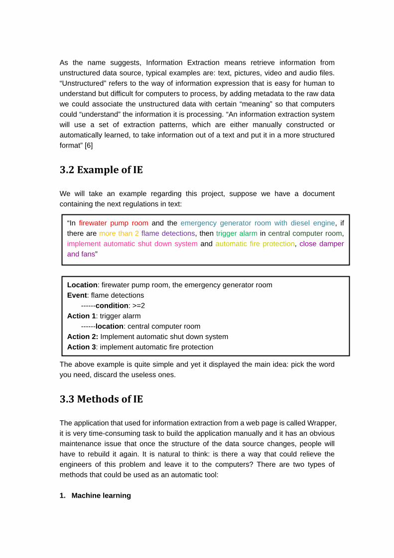
As the name suggests, Information Extraction means retrieve information from unstructured data source, typical examples are: text, pictures, video and audio files. “Unstructured” refers to the way of information expression that is easy for human to understand but difficult for computers to process, by adding metadata to the raw data we could associate the unstructured data with certain “meaning” so that computers could “understand” the information it is processing. “An information extraction system will use a set of extraction patterns, which are either manually constructed or automatically learned, to take information out of a text and put it in a more structured format” [6]
3.2 Example of IE
We will take an example regarding this project, suppose we have a document containing the next regulations in text:
The above example is quite simple and yet it displayed the main idea: pick the word you need, discard the useless ones.
3.3 Methods of IE
The application that used for information extraction from a web page is called Wrapper, it is very time-consuming task to build the application manually and it has an obvious maintenance issue that once the structure of the data source changes, people will have to rebuild it again. It is natural to think: is there a way that could relieve the engineers of this problem and leave it to the computers? There are two types of methods that could be used as an automatic tool: 1. Machine learning
“In firewater pump room and the emergency generator room with diesel engine, if there are more than 2 flame detections, then trigger alarm in central computer room, implement automatic shut down system and automatic fire protection, close damper and fans”
Location: firewater pump room, the emergency generator room Event: flame detections ------condition: >=2 Action 1: trigger alarm ------location: central computer room Action 2: Implement automatic shut down system Action 3: implement automatic fire protection

This type of information extraction depends on the separator in the data source to locate the required information and automatically learning the rules of extraction.
2. Ontology This type of method depends on a knowledge base, which will define extract pattern for each element and relationships among them. It uses ontology to locate the key information and utilize them to build a ontology library.
Both methods requires manually provide samples for the machines to learn the extraction rule and this is not a easy task. As the development of the Internet, Information extraction from a web document attracts more and more attention and has become an intriguing problem, the difference between a web page and a textual file is that web page contains lots of markup, which separate the contents of the page and provide additional information for this web page, so as to extract information from the page. These useful tags could help display the page in a hierarchical way, but the web page itself isn’t structured. Nowadays web pages still use HTML language and because this markup method is only used for displaying purpose, it does not describe any semantic or “meaning” of the page.
3.3 XML and Information Extraction
Unlike HTML, XML does not deal with the display of data but rather the structure of the data. In fact, if the source document and the one that need to be verified were all presented in standardized XML format, IE would be unnecessary. And due to the fact that many words have ambiguity or similarity in certain context. Different engineers may come up with different terms. It is hard to manually annotate documents with appropriate XML tags. Sometimes these industrial files may be considered as confidential and the easy access nature of XML makes this another security issue.
3.4 Limitations of Information extraction system
In this thesis we are mainly concerned about information extraction from SRS, as we all know that even though this type of documents are basically deals with safety system, there are huge amount of information available for it, thus it usually contains a vocabulary that could be used for Information extraction, which requires lot of preparation for the system to be functional, and since the computer process the data according to probabilities, it doesn’t have the ability to understand fuzzy logic like humans do, which may result in ridiculously inaccurate answers. So there may be a lot of room for improvement.

4. Standardizing format
As has been mentioned, for the comparison block the two documents should be in the same format so as to be comparable in programming languages. Following two types of suitable format—XML and RDF are discussed and compared.
4.1 XML
XML (Extensible Markup Language) is an electronically encoding mechanism to format the documents according to a set of rules, it was put forward by the World Wide Web Consortium (W3C) for the generality, simplicity and usability of documents over the Internet, defined in the XML 1.0 Specification[7]. Started in 1996, XML has been combined with many programming interfaces such as Java, C++, C#, etc, additionally XML-based format has been widely used by many application tools and software, it’s also widely used for the representation of arbitrary data structures rather than confining within documents. One of the biggest advantages and features for XML document is its compact and strict format, typically an XML document is made up of the following constructs: 1. Markup and content: All strings begin with “<” and end with “>”, or begin with “&” and end with “;” constitute markups that set up the main format for XML, the other strings are contents for description. 2. Tag: Strings contained within the markups are called tags, there are three types of tags, start tag such as <name>, end tag such as </name>, and empty-element tag such as <name/> 3. Elements: Characters between the start and end tags are called elements that constitute the content, it could also be in the form that only contain an empty-element tag such as <name/> itself. 4. Attribute: It consists of a name or value pair within a start tag or empty-element which belongs to a markup that adds up more information to the tag item. A typical example that includes all the constructs above could be shown as below: <?xml version="1.0" encoding='UTF-8'?> <document> <details> <uri>href="page"</uri>

<author> <name>Ora</name> </author> </details> </document> From the above it could be concluded that XML format is highly-structured and well-formed as correspondent pair of start and end tags represent, making it more scalable and interoperable, satisfying the goal of generality. On the other hand, as XML supports any Unicode characters in the constructs mentioned above, even in a single XML document characters from different languages could exist together, thus this format is widely accepted and used by software and applications all over the world since initiated, satisfying the goal of usability. In this project the output generated by the CEM of the existing system that describing the cause and effect relationships is in the XML format, fragments of the CEM output are shown as below: <ProtectionSheet DocumentName="U13-2">
<AreaClassification>
<Zone1>False</Zone1>
<Zone2>False</Zone2>
<NonHazardLocat>True</NonHazardLocat>
<NonHazardVent>False</NonHazardVent>
</AreaClassification>
This part describes the area which the fire and gas system resides in, the other parts represent each links for causes and effects using XML blocks. The whole file illustrate information of the CEM sheet in quite a structured way.
4.2 RDF
RDF(Resource Description Framework) is a metadata model started also by World Wide Web Consortium (W3C), It is used as a general method for conceptual description or modeling of information that is implemented in web resources, using a variety of syntax formats and provide a lightweight ontology system to support exchanges of knowledge on the Web. The RDF specification integrates a variety of applications from library catalogs and world-wide directories to syndication and aggregation of news, software, and content to personal collections of music, photos

and events using XML as an interchange syntax. It also allows structured and semi-structured data to be mixed, exposed, and shared across different applications. RDF is based on the idea of making web resources in the form of “subject predict object” which are defined as triples. As abstract model, there two serialization formats for RDF: XML format and Notation 3 format of RDF models that is easier for handwriting and easier to follow. Each subject of RDF statement is a URI(Uniform Resource Identifier) or blank node, resources in them sometimes could truly representing actual data on the Internet. It is clearly concluded that rather than XML which represent an annotated tree data model, RDF is based on a directed labeled graph data model. The syntax of an RDF document uses specific XML-based. An RDF example with a simple graph model that it illustrates are show below: <?xml version="1.0"?> <Description xmlns="http://www.w3.org/TR/WD-rdf-syntax#" xmlns:s="http://docs.r.us.com/bibliography-info/" about="http://www.w3.org/test/page" s:Author ="http://www.w3.org/staff/Ora" />
As has been mentioned, RDF mainly deals with the relationships between subjects and objects, thus, it’s more suitable for semantic framework that emphasizes inference over constraint. It could be found that in analyzing relations of words that has a structure more like a graph than a tree, RDF has advantages over XML as it’s more or less constructing a relational model rather than following a well-formed format[11]. The body of knowledge modeled by a collection of statements may be subjected to reification, in which each statement (that is each triple subject-predicate-object altogether) is assigned a URI and treated as a resource about which additional statements can be made, as in "Jane says that John is the author of document X". Reification is sometimes important in order to deduce a level of confidence or degree of usefulness for each statement.

In a reified RDF database, each original statement, being a resource, itself, most likely has at least three additional statements made about it: one to assert that its subject is some resource, one to assert that its predicate is some resource, and one to assert that its object is some resource or literal. More statements about the original statement may also exist, depending on the application's needs.
The body of knowledge modeled by a collection of statements may be subjected to reification, in which each statement (that is each triple subject-predicate-object altogether) is assigned a URI and treated as a resource about which additional statements can be made, as in "Jane says that John is the author of document X". Reification is sometimes important in order to deduce a level of confidence or degree of usefulness for each statement.
In a reified RDF database, each original statement, being a resource, itself, most likely has at least three additional statements made about it: one to assert that its subject is some resource, one to assert that its predicate is some resource, and one to assert that its object is some resource or literal. More statements about the original statement may also exist, depending on the application's needs.
Borrowing from concepts available in logic (and as illustrated in graphical notations such as conceptual graphs and topic maps), some RDF model implementations acknowledge that it is sometimes useful to group statements according to different criteria, called situations, contexts, or scopes, as discussed in articles by RDF specification co-editor Graham Klyne[9]. For example, a statement can be associated with a context, named by a URI, in order to assert an "is true in" relationship. As another example, it is sometimes convenient to group statements by their source, which can be identified by a URI, such as the URI of a particular RDF/XML document. Then, when updates are made to the source, corresponding statements can be changed in the model, as well.
Implementation of scopes does not necessarily require fully reified statements. Some implementations allow a single scope identifier to be associated with a statement that has not been assigned a URI, itself. Likewise named graphs in which a set of triples is named by a URI can represent context without the need to reify the triples
Now that the formats that could be used to represent the documents that are to be checked in the comparison block have been introduced, it’s time to combine with the situation of this project to decide which format or model is more suitable.

4.3 XML vs RDF
First we compare them form a global overview. There was a clear difference of view between those who wanted to query documents and those who wanted to extract the "meaning" in some form and query that. From the syntax view, since most of the RDF documents use more or less the same constructs as XML, both are almost equal. However, as has been mentioned, RDF is based upon a graph data model, making it more convenient for query process.
4.3.1. Simplicity
If the following relationship is to be represented: “The author of the page is Ora” In RDF it’s just a relation triple triple(author, page, Ora)
but in XML it could only be represented following the format like <document>
<details>
<uri>href="page"</uri>
<author>
<name>Ora</name>
</author>
</details>
</document>
It could be seen that although XML is quite general and easy to follow so as to be widely used, it has to follow the strict syntax format, making it not so concise as RDF model, which uses triple to identify ”predicate” relations.
4.3.2. Tree and graph structure for relation and query
XML documents could have a number of different representations, to a person reading then they mean the same thing [8]. To a machine parsing them, they produce different XML trees. For instance, in the following XML document <v>
<x>
<y> a="ppppp"</y>
<z>
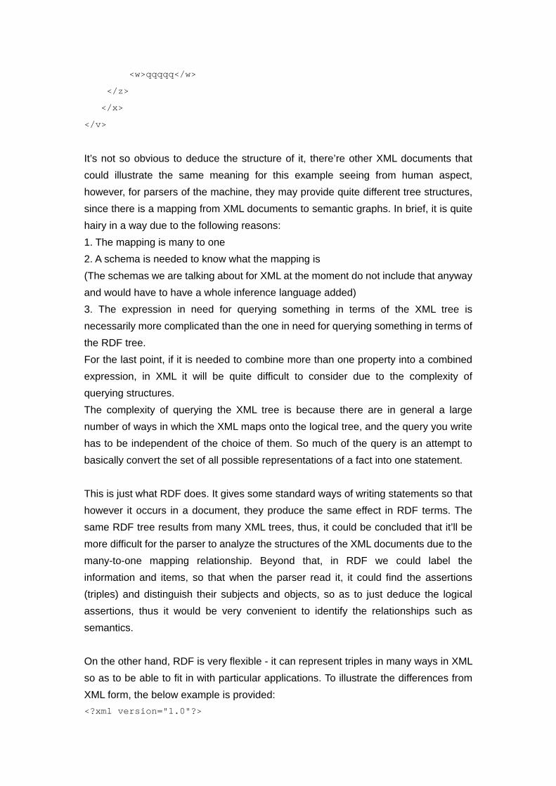
<w>qqqqq</w>
</z>
</x>
</v>
It’s not so obvious to deduce the structure of it, there’re other XML documents that could illustrate the same meaning for this example seeing from human aspect, however, for parsers of the machine, they may provide quite different tree structures, since there is a mapping from XML documents to semantic graphs. In brief, it is quite hairy in a way due to the following reasons: 1. The mapping is many to one 2. A schema is needed to know what the mapping is (The schemas we are talking about for XML at the moment do not include that anyway and would have to have a whole inference language added) 3. The expression in need for querying something in terms of the XML tree is necessarily more complicated than the one in need for querying something in terms of the RDF tree. For the last point, if it is needed to combine more than one property into a combined expression, in XML it will be quite difficult to consider due to the complexity of querying structures. The complexity of querying the XML tree is because there are in general a large number of ways in which the XML maps onto the logical tree, and the query you write has to be independent of the choice of them. So much of the query is an attempt to basically convert the set of all possible representations of a fact into one statement. This is just what RDF does. It gives some standard ways of writing statements so that however it occurs in a document, they produce the same effect in RDF terms. The same RDF tree results from many XML trees, thus, it could be concluded that it’ll be more difficult for the parser to analyze the structures of the XML documents due to the many-to-one mapping relationship. Beyond that, in RDF we could label the information and items, so that when the parser read it, it could find the assertions (triples) and distinguish their subjects and objects, so as to just deduce the logical assertions, thus it would be very convenient to identify the relationships such as semantics. On the other hand, RDF is very flexible - it can represent triples in many ways in XML so as to be able to fit in with particular applications. To illustrate the differences from XML form, the below example is provided: <?xml version="1.0"?>

<Description
xmlns="http://www.w3.org/TR/WD-rdf-syntax#"
xmlns:s="http://docs.r.us.com/bibliography-info/"
about="http://www.w3.org/test/page"
s:Author ="http://www.w3.org/staff/Ora" />
The "description" RDF element gives the clue to the parser as to how to find the subjects, objects and verbs in what follows, so that to generate clear structure of the subject-object relationship for a graph representation. Thus in RDF for the querying process, the semantic tree could be parsed, which end up providing a set of (possibly mutually referential) triples and then you can use the ones you want ignoring the ones you don't understand. While in XML when an XML schema changes, it could typically introduce new intermediate elements (like "details" in the tree above or "div" is HTML). These may or may or may not invalidate any query which has been based on the structure of the document.
4.3.3. Exchange of data
For information, differences in syntax description could be solved by the necessary data format conversions to change the desired information into a format that the targeted application could deal with. Of course the more ideal situation is to let all the information to be described following the same syntax and language, thus the initiation of XML makes it possible to let different sorts of data structures to be represented by the same format. XML has become the true representation of data representation and exchange on the Web and a way to share data between different applications and machines. The development of XML and its relating technologies has driven forward the uniform of syntax description in information expression and exchange, so that more and more application has began to select XML as the syntax description mode for data, setting, information and service. Nowadays, XML has become the most ideal way for data representation on the web. One of the special features that makes XML differs from other mark language is its scalability. The core of XML is to build the structure that data represent in a standardized way while leave the definition of detailed marking to the users. This scalability makes XML could satisfy the needs of data description from various fields and be able to encode any

data that is exchanged between different machines. But XML is enough? When we first encounter XML, we might be excited about the representation ability, scalability and other bright future ahead. But one question comes ahead: how to realize the exchange process between information or data from two different XML document? Would it be the case that once we put these documents into XML format, then it will be ok for the data exchange of the two? XML provides us with a format that could be read by the application automatically, but it doesn’t provide a way promote to the level for supporting automatic data exchange, we still need special program to explain the data contained in XML documents to acquire the parts which the targeted application could deal with, it’s worth noting that the explanation here is different from analysis of the XML document, although analysis of the XML documents is necessary for the whole explanation[10]. XML has several kinds of parsers, but the function of them is to load and process XML document rather than provide the whole explanation that contains an illustration of the whole structure. Thus we have to explain the contents of XML document using specific application program, and it’s obvious that these programs don’t have the ability to exchange and inter-operate. However, the above question could be solved by using RDF format as the model represent the relationship in quite a clear way from the directed graph so that we don’t need parsers to provide the detailed explanation—it could clearly be seen from the triples that indicate the subject-predict-object relationship. For a summary it could be conclude that XML 1. Is a purely syntactic framework for structured data and documents 2. Is based on an annotated tree data model 3. Defines structure, not semantics 4. XML schema constrains the syntax of conforming XML documents 5. Ad-hoc composition RDF 1. Uses a specific XML based syntax 2. Is based on a directed labeled graph data model 3. Is a semantic framework (as XML is a syntactic framework) 4. RDF schema emphasizes inference over constraint
5. General composition For the given project, for the reason of semantic extraction, RDF model is more suitable for the comparison block, since for the two documents—output of the CEM and the other generated from the standards, the terminologies could not exactly match. Thus a number of ontology should be built to analyze the relationships and link the correspondent terminologies that have the same meaning so as to let the data exchange process in the comparison block work. However, due to the fact that the CEM output file is already in the XML format, and XML has already been accepted and widely used by a number of programming languages. So in the end for the reason of convenience XML format is chosen as the implementation of comparison block.

5. Ontologies and applications
5.1 Ontology introduction
5.1.1 Original meaning of ontologies
Ontology is the philosophical study of the nature of being, existence or reality in general, as well as the basic categories of being and their relations. Traditionally listed as a part of the major branch of philosophy known as metaphysics, ontology deals with questions concerning what entities exist or can be said to exist, and how such entities can be grouped, related within a hierarchy, and subdivided according to similarities and differences[12]. One common approach is to divide the extant entities into groups called categories. Of course, such lists of categories differ widely from one another, and it is through the co-ordination of different categorical schemes that ontology relates to such fields as library science and artificial intelligence. Such an understanding of ontological categories, however, is merely taxonomic, classificatory. The categories are, properly speaking, the ways in which a being can be addressed simply as a being, such as what it is, how it is, how much it is, where it is, its relatedness to other beings, etc.
5.1.2 Ontologies in computer science
In computer science and information science, ontology is a formal representation of the knowledge by a set of concepts within a domain and the relationships between those concepts. It is used to reason about the properties of that domain, and may be used to describe the domain. In theory, an ontology is a "formal, explicit specification of a shared conceptualisation". [13] An ontology provides a shared vocabulary, which can be used to model a domain — that is, the type of objects and/or concepts that exist, and their properties and relations. Ontologies are used in artificial intelligence, the Semantic Web, systems engineering, software engineering, biomedical informatics, library science, enterprise bookmarking, and information architecture as a form of knowledge representation about the world or some part of it. The creation of domain

ontologies is also fundamental to the definition and use of an enterprise architecture framework.
5.1.3 Component of ontologies
Contemporary ontologies share many structural similarities, regardless of the language in which they are expressed. [14]As mentioned above, most ontologies describe individuals (instances), classes (concepts), attributes, and relations. In this section each of these components is discussed in turn. Common components of ontologies include: 1. Individuals: instances or objects (the basic or "ground level" objects) 2. Classes: sets, collections, concepts, classes in programming, types of objects, or kinds of things. 3. Attributes: aspects, properties, features, characteristics, or parameters that objects (and classes) can have 4. Relations: ways in which classes and individuals can be related to one another 5. Function terms: complex structures formed from certain relations that can be used in place of an individual term in a statement 6. Restrictions: formally stated descriptions of what must be true in order for some assertion to be accepted as input 7. Rules: statements in the form of an if-then (antecedent-consequent) sentence that describe the logical inferences that can be drawn from an assertion in a particular form 8. Axioms: assertions (including rules) in a logical form that together comprise the overall theory that the ontology describes in its domain of application. This definition differs from that of "axioms" in generative grammar and formal logic. In those disciplines, axioms include only statements asserted as a priori knowledge. As used here, "axioms" also include the theory derived from axiomatic statements. 9. Events: the changing of attributes or relations Ontologies are commonly encoded using ontology languages. An example of ontology structure could be presented as below:

Figure 9 Example of ontology structure
5.1.4 Ontology engineering
Ontology engineering (or ontology building) is a subfield of knowledge engineering that studies the methods and methodologies for building ontologies. It studies the ontology development process, the ontology life cycle, the methods and methodologies for building ontologies, and the tool suites and languages that support them. Ontology engineering aims to make explicit the knowledge contained within software applications, and within enterprises and business procedures for a particular domain. Ontology engineering offers a direction towards solving the interoperability problems brought about by semantic obstacles, such as the obstacles related to the definitions of business terms and software classes. Ontology engineering is a set of tasks related to the development of ontologies for a particular domain.
5.2 Ontology language(OWL)
5.2.1 Ontology language
An ontology language is a formal language used to encode the ontology. There are a number of such languages for ontologies, both proprietary and standards-based. OWL is a language for making ontological statements,

developed as a follow-on from RDF and RDFS, as well as earlier ontology language projects including OIL, DAML and DAML+OIL. OWL is intended to be used over the World Wide Web, and all its elements (classes, properties and individuals) are defined as RDF resources, and identified by URIs.
5.2.2 Status of ontology in the project
In this project, ontologies are mainly built as links in the comparison block. As has been mentioned, it is the aim to generate the comparison result between the XML output from the CEM and the document extracted from the desired standards. Since the terminologies that describing the same concepts might be different In the two concept, it would be necessary in the part of XML comparison programme to add some in-built terminologies which could make the computer recognize that different words are of the same meaning and treat them as same concept for comparison. Thus, ontologies here are used as a dictionary for subordinate functions of searching, correspondence and relating, a graph that illustrates the status of ontologies is presented as below, with the addition of ontology functions that extracted from both documents, the comparison and validation block could implement its work without having to provide specific indications to let the computer know that different terminologies represent the same concept.
Cause-and Effect
Text Standard
Extracted information
XML representation of standards
Ontology
Output document (XML)
Comparison and validation

Figure 10. Status of ontologies in this project
After identifying the usage of ontologies, it would be the next step to select implementation languages or application tools. Efficient development tools are a prerequisite for the wide adoption of a new technology. For instance, visual web design tools like DreamWeaver have significantly reduced the development costs of Internet content, and have brought Web technology to the fingertips of people who are not familiar with the details of HTML. The concept of the Semantic Web is often regarded as the next “big” technology leap for the Internet. Now that the Web Ontology Language (OWL) has been officially standardized, it is the task of tool builders to explore and provide suitable infrastructures that help make the Semantic Web vision a reality.
5.2.3 OWL and its sub-languages
The Web Ontology Language (OWL) is a family of knowledge representation languages for authoring ontologies endorsed by the World Wide Web Consortium. They are characterized by formal semantics and RDF/XML-based serializations for the Semantic Web. OWL has attracted academic, medical and commercial interest. OWL has three sublanguages that are: OWL-Lite, OWL-full, and OWL-DL. OWL-Lite is the simplest one that is used to illustrate simple class hierarchies with few constraints. For the OWL-DL, it’s based on the description language that could accomplish the task of automatic reasoning, consistency checking and establishment of class hierarchies. The OWL-full is compatible with RDF schemas and is the most complicated one that could be used when the other two languages are not sufficient to handle the class hierarchies as well as the constraints. These three languages are layered in a sense that every legal OWL-Lite ontology is a legal OWL DL ontology, every legal OWL DL ontology is a legal OWL Full ontology, every valid OWL-Lite conclusion is a valid OWL DL conclusion, and every valid OWL DL conclusion a valid OWL Full conclusion.[15] The inverses of these relations generally do not hold. Also, every OWL ontology is a valid RDF document (i.e., DL expressions are mapped to triples), but not all RDF documents are valid OWL-Lite or OWL DL documents. In this project for simplicity and the automatic completion process the OWL-DL is chosen, also Protégé is used as the application tools while
FaCT++ is selected as the semantic reasoning analyzer that is embedded within Protégé.
5.2.4 OWL-DL with its syntax
As we can see, OWL DL is the description logic SHOIN with support of data values, data types and data-type properties, i.e., SHOIN(D), but since OWL is based on RDF(S), the terminology slightly differs. A concept from DL is referred to as a class in OWL and a role from DL is referred to as a property in OWL. Also for description of OWL ontology or knowledge base, the DL syntax can be used. There is an "abstract" LISP-like syntax defined that is easier to write in ASCII character set (see also the first and the second table below). Since OWL is syntactically embedded into RDF, all of the RDF serializations can be used. RDF/XML is the normative syntax and should be used to exchange information between systems. The OWL DL descriptions, data ranges, properties, individuals and data values syntax and semantics are summarized in the first table below, OWL DL axioms and facts are summarized in the second table below.

Table2. OWL-DL descriptions, data ranges, individuals and data values

Table 3. OWL-DL axioms and facts
5.3 Protégé and FaCT++--implementation and reasoning
tools
5.3.1 Protégé and its structures
Protégé is an open platform for ontology modelling and knowledge acquisition. The OWL Plug-in can be used to edit OWL ontologies, to access description

logic (DL) reasoners, and to acquire instances for semantic mark-up. Protégé has a community of thousands of users. Although the development of Protégé has historically been mainly driven by biomedical applications, the system is domain-independent and has been successfully used for many other application areas as well. The Protégé integrates OWL syntax and establishes ontologies using class hierarchy with the support of relations and logic descriptions of OWL syntax. The following table is the snapshot from Protégé to illustrate most frequently used syntax with the meanings and specific examples:
Figure11. Example of Protégé-OWL syntax
Like most of the modelling tools, the architecture of Protégé is separated into two parts: the “model” and “view” parts. Protégé’s model is the internal representation mechanism for ontologies and knowledge bases.[16] Protégé’s view components provide a user interface to display and manipulate the underlying model. Protégé’s model can represent ontologies consisting of classes, properties, property characteristics and instances. The default class of the Protégé base system is the STANDARD CLASS and has properties such as :NAME and :DIRECT-SUBCLASSES, this structure is quite suitable for extension, scalability and adoption by other systems.[17] What users most frequently deal with is the user interface of Protégé’s view components, in which users could create classes assign properties to the classes, establish class hierarchies that representing super or sub-class relationships, make links for different classes that describing the same concept, and restrict the properties’ facets at certain classes. For each class in the ontology, the system creates one form with editing components for each property of the class, The generated forms can be further customized with

Protégé’s form editor, where users can select alternative user interface widgets for their project. In addition to the collection of standard tabs for editing classes, properties, forms and instances, a library of other tabs exists that perform queries, access data repositories, visualize ontologies graphically, and manage ontology versions [18]. An example illustrating user interface and class hierarchies built within Protégé is shown as below:
Figure12. Protégé class hierarchy From the figure it could be found the overall class relationships could be represented the time users have finished the creation process. On the other hand, other in-built functionalities such as equivalent class, super-class, disjoint class and members could provide users convenience to construct the relationship of the whole system within a single hierarchy or several relating hierarchies, the below figure shows the sub-functions which could be used to support main class structure establishment:

Figure13. Protégé subordinate functions
5.3.2 Reasons for choosing Protégé
Now that the application tool has been introduced for its functionalities and structures, but why Protégé is selected as the ontology establishment tools and the system should build on its top? Since ontologies play such an important role in Semantic Web applications, it was straight-forward to take an existing ontology development environment as a starting point. Some of the reasons could be listed as the following: 1. Protégé provides a highly scalable database back-end, allowing users to create ontologies with hundreds of thousands of classes. 2. In Protégé there’re a number of built-in library of plug-ins, which could directly be used in OWL or adapted by other applications of OWL. 3. Protégé is an open-source application software, this feature will encourage more and more plug-ins to be developed to provide users with more convenience. 4. Protégé is backed by quite a considerable number of users and developers, feedback from those people could provide refinement of this application to make it more suitable in creating ontologies and implementation of OWL.

5. Protégé currently can be used to load, edit and save ontologies in various formats, including CLIPS, RDF, XML, UML and relational databases, and the formats that is used in the comparison block is just in the XML form.
5.3.3 Protégé with OWL plug-in
Next the architecture of Protégé as well as the OWL plug-in model are briefly introduced. The OWL plug-in provides access to OWL-related services such as classification, consistency checking, and ontology testing within the Protégé and extends the Protégé model and its API with classes to represent the OWL specification, the relationship structure with Protégé could be shown in the following figure:
Figure14. Protégé with OWL plug-in
After the class hierarchy has been constructed, the next step would be to analyze the established model and try to represent the entire model in a way that could be added into the comparison and validation of the XML-format documents, thus a semantic reasoner is needed and FaCT++ is chosen here for the analysis and reasoning of the user-constructed model.

5.3.4 FaCT++--analyzing and reasoning
FaCT++ is a new DL reasoner designed as a platform for experimenting with new tableaux algorithms and optimization techniques. It supports OWL DL and (partially) OWL 2 and is released under a GNU public license and is available for download both as a binary file and as source code. To build FaCT++, a C++ compiler and GNU make are both needed. In order to build a DIG version of a reasoner, the XML parsing library Xerces-C++ is also required. FaCT++ incorporates most of the standard optimization techniques, including those introduced in the FaCT system, but also employs many novel ones. [19] When we finish the class hierarchy set-up process and use FaCT++ as reasoner to classify the class relationships, the following example figure that illustrating part of the cause-and-effect matrix of this project are reasoning and analyzing is shown:
Figure15. Class structure after reasoning

From the graph it could be seen that different terminologies are classified to their super-classes and the process goes on until the main default class “Thing” is reached, constructing a tree-structure. For both documents that are to be checked in the comparison block, such a structure of representation could be established after reasoning. Thus, using the subordinate function of equivalent classes in the Protégé user interface, ontologies could be set up by indicating that different leaf elements for the two class hierarchies mean the same concept. During the comparison process, after the corresponding ontologies from different documents have been found, the compiler would go through the tree structure for their super-classes to identify the positions in the CEM, reducing considerable time and efforts.

6. Verification implementation
6.1 verification process
Now we assume that the raw data has been translated in to a structured form like RDF or XML, manually or by using expert system, the next step is to verify that if these two match. In the process of verification, we have to represent the CEM of interest in a form that is consistent with the document, in this project we choose to transform them both into XML format before we conduct comparison. For convenient purpose here only a piece of a XML will be presented as an example:
Figure 16 Standardization of two files in different forms There are two types of verifying approach: The user may have a specific rule that need to be certain if it’s in the generated specification, he will input the name of the rule to the user interface and the result will be given as “Find” or “Missing”.
The user could also verify the entire specification to see if everything in the document is included in it. He could take both XML files as inputs and let the application to traverse through all the nodes to see if there is any discrepancy between them. The problem is translated as a form of comparison between two XML files. Consider two XML files, Compared.xml and Reference.xml. At first the two files contain exactly the same contents:
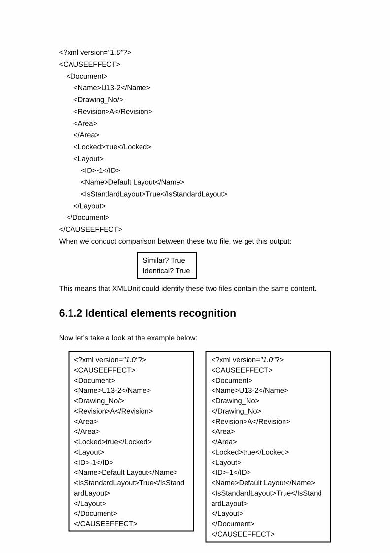
<?xml version="1.0"?> <CAUSEEFFECT> <Document> <Name>U13-2</Name> <Drawing_No/> <Revision>A</Revision> <Area> </Area> <Locked>true</Locked> <Layout> <ID>-1</ID> <Name>Default Layout</Name> <IsStandardLayout>True</IsStandardLayout> </Layout> </Document> </CAUSEEFFECT> When we conduct comparison between these two file, we get this output: This means that XMLUnit could identify these two files contain the same content.
6.1.2 Identical elements recognition
Now let’s take a look at the example below:
Similar? True Identical? True
<?xml version="1.0"?> <CAUSEEFFECT> <Document> <Name>U13-2</Name> <Drawing_No/> <Revision>A</Revision> <Area> </Area> <Locked>true</Locked> <Layout> <ID>-1</ID> <Name>Default Layout</Name> <IsStandardLayout>True</IsStandardLayout> </Layout> </Document> </CAUSEEFFECT>
<?xml version="1.0"?> <CAUSEEFFECT> <Document> <Name>U13-2</Name> <Drawing_No> </Drawing_No> <Revision>A</Revision> <Area> </Area> <Locked>true</Locked> <Layout> <ID>-1</ID> <Name>Default Layout</Name> <IsStandardLayout>True</IsStandardLayout> </Layout> </Document> </CAUSEEFFECT>

Reference Compared Because in XML using start tag and end tag express the same meaning as using “/” at the end of a single tag if it is an empty element, the XMLUnit could understand the two forms of expression are actually saying the same thing, so it will give the results:
6.1.3 Comparison between elements in different order
But what if the generated XML display certain elements in different sequence while this in fact does not influence the integrity of the code? If we make the following modifications to the code as:
Reference Compared
<?xml version="1.0"?> <CAUSEEFFECT> <Document> <Name>U13-2</Name> <Drawing_No/> <Revision>A</Revision> <Area> </Area> <Locked>true</Locked> <Layout> <Name>Default Layout</Name> <ID>-1</ID> <IsStandardLayout>True</IsStandardLayout> </Layout> </Document> </CAUSEEFFECT>
<?xml version="1.0"?> <CAUSEEFFECT> <Document> <Name>U13-2</Name> <Drawing_No/> <Revision>A</Revision> <Area> </Area> <Locked>true</Locked> <Layout> <ID>-1</ID> <Name>Default Layout</Name> <IsStandardLayout>True</IsStandardLayout> </Layout> </Document> </CAUSEEFFECT>
Similar? True Identical? True

The only changes made here is that two elements switched places with each other. The result of running the program again is: The program examines the two pieces of code and finds out that there is another change occurred in the Compared.xml, the positions of ID element and Name element were interchanged, because of which, the two files are structurally different, so they are not identical even if they have similar pattern. So the program could locate the minor difference between two XML files.
6.1.4 Ignore the comments
When documenting the specifications sometimes it is necessary to add comments or descriptions to the element as an explanation, what will that influence the decision made by XMLUnit? Take a look at the next example:
Similar? true Identical? false *********************** Expected sequence of child nodes '0' but was '1' - comparing <ID...> at /CAUSEEFFECT[1]/Document[1]/Layout[1]/ID[1] to <ID...> at /CAUSEEFFECT[1]/Document[1]/Layout[1]/ID[1] *********************** *********************** Expected sequence of child nodes '1' but was '0' - comparing <Name...> at /CAUSEEFFECT[1]/Document[1]/Layout[1]/Name[1] to <Name...> at /CAUSEEFFECT[1]/Document[1]/Layout[1]/Name[1] ***********************
<?xml version="1.0"?> <CAUSEEFFECT> <Document> <Name>U13-2</Name><!—the room number--> <Drawing_No/> <Revision>A</Revision> <Area> </Area> <Locked>true</Locked> <Layout> <ID>-1</ID> <Name>Default Layout</Name> <IsStandardLayout>True</IsStandardLayout> </Layout> </Document> </CAUSEEFFECT>

Compared
Reference The only difference we have here is the comment line, the rest of the code in Compared.xml is exactly the same as that in Reference.xml. The result of this is:
<?xml version="1.0"?> <CAUSEEFFECT> <Document> <Name>U13-2</Name> <Drawing_No/> <Revision>A</Revision> <Area> </Area> <Locked>true</Locked> <Layout> <ID>-1</ID> <Name>Default Layout</Name> <IsStandardLayout>True</IsStandardLayout> </Layout> </Document> </CAUSEEFFECT>
Similar? false Identical? false *********************** Expected number of child nodes '8' but was '9' - comparing <Document...> at /CAUSEEFFECT[1]/Document[1] to <Document...> at /CAUSEEFFECT[1]/Document[1] *********************** *********************** Expected sequence of child nodes '1' but was '2' - comparing <Description...> at /CAUSEEFFECT[1]/Document[1]/Description[1] to <Description...> at /CAUSEEFFECT[1]/Document[1]/Description[1] *********************** *********************** . . . . . .

Only the first several parts of the result are shown, that’s more than enough to tell us that the two files are neither similar nor identical. But if a human expert was processing this two files, he would think of these two as the same because comments are just descriptive text which has nothing to do with the function and meaning of the Code, so it should be considered as the same. To let XMLUnit to understand this, we could make use of the command: Then the output become: This means that the compiler could understand the function of the comment line and will ignore the “seemingly” extra code if it is a comment.
6.1.5 Ignore the extra space in elements
When building xml document by some computer applications without having to do it manually, we might get the unexpected difference in the code. For example the xml element may contain extra spaces: The compiler will show the error message:
XMLUnit.setIgnoreComments(Boolean.TRUE);
Similar? True Identical? True
<Name>Default Layout</Name> <Name>Default
Similar? false Identical? false *********************** Expected text value 'Default Layout' but was 'Default Layout' - comparing <Name ...>Default Layout</Name> at /CAUSEEFFECT[1]/Document[1]/Layout[1]/Name[1]/text()[1] to <Name ...>Default Layout</Name> at /CAUSEEFFECT[1]/Document[1]/Layout[1]/Name[1]/text()[1] ***********************

But in reality if the extra space does not affect the meaning of the document, engineers would have ignored them and consider this content as the same as Reference document. Then we could set the extra condition to ignore the white space: The result will be both similar and identical. This is optional constraint depend on the actual requirements of the document, if white space does affect the meaning of the content, we could remove this function to get a more strict verification rule.
6.1.6 Identify the missing element
Considering the next scenario:
Compared Reference During the xml construction process, there may be some unintended omissions in the
XMLUnit.setIgnoreDiffBetweenTextAndCDATA(Boolean.TRUE);
<?xml version="1.0"?> <CAUSEEFFECT> <Document> <Name>U13-2</Name> <Drawing_No/> <Revision>A</Revision> <Area> </Area> <Locked>true</Locked> <Layout> <Name>Default Layout</Name> <IsStandardLayout>True</IsStandardLayout> </Layout> </Document> </CAUSEEFFECT>
<?xml version="1.0"?> <CAUSEEFFECT> <Document> <Name>U13-2</Name> <Drawing_No/> <Revision>A</Revision> <Area> </Area> <Locked>true</Locked> <Layout> <ID>-1</ID> <IsStandardLayout>True</IsStandardLayout> </Layout> </Document> </CAUSEEFFECT>

generated file, take the above xml files as an example: The name of the <Layout> element has been removed from the Compared file and the ID of the <Layout>element has been removed from the Reference file, the result will be: The result shows that the ID tag was compared with Name tag and of course the compiler would send an unmatch message, but what if we want the ID and Name tag both be present in the document? Slight changes could be applied by using the following method: The result will still show unmatch messages, but with different reason this time: Alternatively, we could use assertXMLEqual() method to compare two pieces of XML files. For example:
Similar? false Identical? false *********************** Expected element tag name 'Name' but was 'ID' - comparing <Name...> at /CAUSEEFFECT[1]/Document[1]/Layout[1]/Name[1] to <ID...> at /CAUSEEFFECT[1]/Document[1]/Layout[1]/ID[1] *********************** *********************** Expected text value 'Default Layout' but was '-1' - comparing <Name ...>Default Layout</Name> at /CAUSEEFFECT[1]/Document[1]/Layout[1]/Name[1]/text()[1] to <ID ...>-1</ID> at /CAUSEEFFECT[1]/Document[1]/Layout[1]/ID[1]/text()[1] ***********************
XMLUnit.setCompareUnmatched(Boolean.FALSE);
Similar? false Identical? false *********************** Expected presence of child node 'Name' but was 'null' - comparing <Name...> at /CAUSEEFFECT[1]/Document[1]/Layout[1]/Name[1] to at null *********************** *********************** Expected presence of child node 'null' but was 'ID' - comparing at null to <ID...> at /CAUSEEFFECT[1]/Document[1]/Layout[1]/ID[1] ***********************

Now we’ve seen some basic but useful functions provided by the XMLUnit, it’s quite skillful in terms of dealing with XML files, especially conducting comparison between files and it showed a lot of flexibilities that could be customized by engineers according to specific requirements.
6.2 Limitations of this verification process
There is one more scenario which we need to discuss, when we want to compare a machine generated XML file with a engineer produced XML file, there must be some terms that represent the same thing but with different names, this is almost inevitable, because the machine doesn’t think like the engineer does, it couldn’t understand the connection between an object with difference expressions, like “the pet that barks at the neighbors” with “dog”, which would instantly be understood by human that these two are actually describing the same animal. But if the machine received these two objects it would identify these two as distinct unless being told otherwise. In our case, a safety rule could be described differently, for example,The cause and effect matrix may express the following meaning: “When detect confirmed fire (2ooN), start off coincident fire LED and visual alarm platform wide, then start fire damper”. While the document table states:
Table 4 safety specifications AFP: activate fire protection. HVAC: heating, ventilation and air conditioning.
Area/Room Type of detection
Alarm type Automatic shut down
Automatic AFP
HVAC interface
Firewater pump room
and em.generator
room with diesel engine
Flame 1ooN
CCR
None
None
None
Flame 2ooN
CCR
None
Release AFP
Close damper And fans
public void testForEquality() throws Exception { String myControlXML = "AAAAAAAAAAA"; String myTestXML = "BBBBBBBBBBBB"; assertXMLEqual("Comparing test xml to control xml", myControlXML, myTestXML);

CCR: Central computer room Engineers could understand that the “”alarm type CCR” in the table is correspond to the “coincident fire LED and visual alarm platform wide” and the “start fire damper” is correspond to “Release AFP”, so he will not notify this as a mistake or missing element. But when machine is coping with this information, it will send warning that “couldn’t find type of alarm” or lack of description of “Automatic AFP”. In order for the machines to learn that connection, it is natural to think of coming up a vocabulary to do the “mapping”. This “vocabulary” will connect the two types of expression, when the application finds an inconsistency in the two compared files, then it will look up the vocabulary to see if there is a connection, if the connection indicates this discrepancy in the name is just a “false positive”, it will ignore the difference and move on, if there isn’t a connection for the different names then it will mark this as a discrepancy and send a warning to the user interface. Building this vocabulary takes a lot of time and it doesn’t seem to have scalability because every time a new document is about to be processed the engineers have to build a new vocabulary for the document,so the scalability issue could not be addressed in this practice.

7. Discussion In this chapter we will discuss the possibility of automatic information extraction. The ultimate goal of the research in expert system used for automatic information extraction is that machines could “understand” the key information from natural language used by human and arrange them into a form that is readable by computers. It has some inherent difficulties because of the ambiguity existed in natural language, to fully understand the context takes a lot of knowledge and capabilities of inference, how to store these data in the computer in a proper form so as to be able to use them to eliminate the ambiguity is not easy task. In other words, a word may have multiple meanings in different context and a single object may have different words used to express them. With the help of ontology technology, we could establish formal representation of a variety of concepts and have a clear view of the relationships among them, so ontology could be used to establish connections between different object or concept. In the process of verification of two documents, being able to identify the meaning of the element is a necessary function. In this project we simply transform the process of comparing two documents into a comparison between two XML files, because the data is already stored as XML format in the database and XML is a common tool in representing data. But the RDF is known as a better choice than XML when it comes to represent the concept model in knowledge domain. XML uses the structure of the files to express the relationships, such as nesting of elements, adjacent elements, attribute of the elements. Apparently it is not suitable for representing concept model. When data is represented by XML language, the semantics have to be embedded in the language syntax, thus a large portion of semantic information could be lost this way. The verification makes use of XMLUnit, which is suitable for the requirement of the project. It enables us to verify if a system generated information is consistent with the data stored in database.
8. Conclusion and future work
8.1 Conclusion
Information and Communication technology have proved its usefulness in the Oil & Gas industry, especially in respect of control process such as Safety Instrumented Systems. SIS is a necessary component in the process industry and it serves as a reliable guardian against hazardous event. As a sub system inside the whole process system, SIS itself is complex enough for engineers making huge effort to plan in detail just in order to build it. There are a variety of standards and polices for each process industry, reading through every one of the documents presents a big burden for the engineers and that is where the idea of automatic document processing jumped in. Origo has developed a prototype of Cause and Effect editor and it has to be manually operated by human to generate Cause and Effect Matrix sheet, we analyzed the possibility of automatic information extraction and the application of ontology technology. We also analyzed the applications of XML, RDF and OWL of the semantic web technology. The pros and cons of choosing XML format and RDF model are analyzed and the reason why XML is chosen is provided. We find a suitable tool XMLUnit to implemented the verification process of two XML files, which could be perfected and further developed to cope with comparison between industry standards. In addition to that, ontologies are built using application tools of OWL to make the comparison program work without manual indication of objects that represent the same concept. Thus we make the conclusion that the verification of the specifications could be achieved by compare two files in common format, XML and ontology could be used to establish the mapping between elements. Also the use of natural language processing could contribute to the effort of making automatic information process.
Future work
We tested the verifying application in the project as a proof of the advantages of automatic processing technique, but it has a lot of room for improvement, the following features could be developed in the future to make this application more user friendly and powerful: 1. User interface with full functional options such as “search through XML file” and
“Check inconsistency between files”. 2. Incorporate the ontology mapping function into that application so that it could

operate in a more intelligent way and avoid “false positive”. 3. Using the default library provided by the ISO, fulfill the scalability attributes of the
ontology-building process, so that automatic matching could be realized without having to establish ontologies each time for different documents.
The expected expert system will be able to provide automatic information extraction. It is possible to develop this system by either arranging the texture structure so as to make it easier for computers to extract information or applying Natural Language Processing.
Reference [1] Safety instrumented system: Available from http://en.wikipedia.org/wiki/Safety_instrumented_system [2] Safety Requirements Specification Guideline: Available from http://www.sp.se/sv/index/services/functionalsafety/Documents/Safety%20requirements%20specification%20guideline.pdf [3] Bill Manaris: 《Natural language processing: A human-computer interaction perspective>, Advances in Computers, Volume 47,1999》 [4] The development characteristic and discipline position of Natural Language Processing. Feng Zhiwei [5] Riloff and Lorenzen, 1999, p.169 [6] Information Extraction: Algorithm and prospects in a Retrieval Context Marie-Francine Moens [7] "XML 1.0 Origin and Goals". Available from http://www.w3.org/TR/REC-xml/#sec-origin-goals Retrieved July 2009. [8] Tim Berners-Lee, Why RDF model is different from the XML model ,An attempt to explain the difference between the XML and RDF models; Available from www.w3.org/DesignIssues/RDF-XML [9] RDF semantics; Available from http://www.w3.org/TR/rdf-mt/ [10] Jingtao Zhou, Mingwei Wang, XML+RDF-- Realization of description of web-data based on semantics [11] Graham Klyne, Semantic Web and RDF; Available from http://www.ninebynine.org/Presentations/20040505-KelvinInsitute.pdf [12] Ontology in philosophy [cited 13th May]; Available from http://en.wikipedia.org/wiki/Ontology [13] Ontology in computer science [cited 14th May]; Available from http://en.wikipedia.org/wiki/Ontology_(information_science) [14] OWL Web Ontology Language Reference W3C Recommendation 10 February

2004 [cited 1st. April]; Available from: http://www.w3.org/TR/owl-ref/ [15] Web Ontology Language OWL [cited 22nd April]; Available from http://www.obitko.com/tutorials/ontologies-semantic-web/web-ontology-language-owl.html [16] Holger Knublauch, Ray W. Fergerson, Natalya F. Noy and Mark A. Musen, The Protégé OWL Plugin: An Open Development Environment for Semantic Web Applications [17] N. Noy, M. Sintek, S. Decker, M. Crub´ezy, R. Fergerson, and M. Musen. Creating Semantic Web contents with Prot´eg´e-2000. IEEE Intelligent Systems, 2(16):60–71, 2001. [18] I. Horrocks, P. F. Patel-Schneider, and F. van Harmelen. From SHIQ and RDF to OWL: The making of a web ontology language. Journal of Web Semantics, 1(1), 2003. [19] Dmitry Tsarkov and Ian Horrocks, FaCT++ Description Logic Reasoner: System Description. In Proc. of IJCAI 2005, 2005.