An experimental investigation on bushing geometrical ...
12
Article 1 An experimental investigation on bushing 2 geometrical properties and density, in thermal 3 frictional drilling 4 Zülküf Demir 1* , Cebeli Özek 2 and Muhammed Bal 2 5 1 Batman University, Faculty of Engineering and Architecture, Department of Mechanical Engineering, 6 Batman, Turkey, [email protected] 7 2 Firat University, Faculty of Technology, Department of Mechanical Engineering, [email protected] 8 * Correspondence: [email protected]; Tel.: +90-505-438-2701 9 10 Abstract: In thermal friction drilling (TFD) operations, the geometrical dimensions of bushing 11 shape, height and wall thickness are the most vital consequences, due to increasing the connecting 12 length and strength. In this paper, AA7075-T651 aluminum alloys with 2, 4, 6, 8, and 10 mm in 13 thicknesses were drilled with TFD process in order to investigate the density, the volume ratio, and 14 height and wall thickness of the bushings. The experiments were conducted at constant spindle 15 speed and feed rate conditions by using HSS conical tools of 5, 10, 15, and 20 mm in diameters. It 16 was experimentally found that the bushing height and the wall thickness were tendency of increase 17 linearly with increasing both material thickness and tool diameter. The effect of tool diameter was 18 found to have much of influence on the measured values than the thickness of the drilled material. 19 The density of the bushing was changed inconsiderably. Approximately 70-75 % percentages of the 20 evacuated material composed the bushing shape, in TFD operations. 21 Keywords: thermal friction drilling; bushing density; bushing shape; bushing height; bushing 22 volume ratio; bushing wall thickness. 23 1. Introduction 24 Friction drilling is a hole production method, in which the metal cast sheet materials were drilled 25 without cutting, due to the sample material is heated up by the effect of the friction, in the area of the 26 conical tool and material contacting. The generated temperature makes the sample softened and then 27 it is pushed by the tool downward, where tool proceeding into the material to generate the bushing 28 formation, increasing the connection strength in sheet materials. Therefore, investigation of the 29 bushing formation is the main goal of the TFD operations [1]. It is generally desired to obtain only 30 the bushings with a cylindrical shape, having no cracks and petal formations, in order to increases 31 the connecting strength [2]. Higher bushing length leads to a more screwing area as well as increasing 32 the connection strength in sheet materials [3]. Bushing shape, especially bushing height and wall 33 thickness, depends on both the thickness of the drilled material (t) and the diameter of the hole (d), 34 and hence it depends on the ratio of (t/d) [4]. Bushing shape is completed in five steps and categorized 35 according to the geometrical regions of the conical tool and proceeding dimension of the tool into the 36 material [5]. The bushing height is measured to be approximately 2 – 3 times of the (t) [6]. 37 A decrease in bushing height leads to an increase in the wall thickness of the bushing formation, 38 which provides move screwing area by connecting of sheet materials [7-10]. The height of the bushing 39 depends on the d rather than the (t). The height of the bushing does not change with (t), for selecting 40 constant hole diameters [11]. However, cracks and petal formations on the bushings cause to decrease 41 the strength of the connections. Furthermore, deformation and fracture of the drilled material cause 42 to the occurrence of petal formation and cracks on bushing shape. A better-selected tool geometry 43 provides improving bushing formations [12]. 44 Preprints (www.preprints.org) | NOT PEER-REVIEWED | Posted: 12 November 2018 doi:10.20944/preprints201811.0263.v1 © 2018 by the author(s). Distributed under a Creative Commons CC BY license. Peer-reviewed version available at Appl. Sci. 2018, 8, 2658; doi:10.3390/app8122658
Transcript of An experimental investigation on bushing geometrical ...

Article 1
An experimental investigation on bushing 2
geometrical properties and density, in thermal 3
frictional drilling 4
Zülküf Demir 1*, Cebeli Özek 2 and Muhammed Bal 2 5 1 Batman University, Faculty of Engineering and Architecture, Department of Mechanical Engineering, 6
Batman, Turkey, [email protected] 7 2 Firat University, Faculty of Technology, Department of Mechanical Engineering, [email protected] 8 * Correspondence: [email protected]; Tel.: +90-505-438-2701 9 10
Abstract: In thermal friction drilling (TFD) operations, the geometrical dimensions of bushing 11 shape, height and wall thickness are the most vital consequences, due to increasing the connecting 12 length and strength. In this paper, AA7075-T651 aluminum alloys with 2, 4, 6, 8, and 10 mm in 13 thicknesses were drilled with TFD process in order to investigate the density, the volume ratio, and 14 height and wall thickness of the bushings. The experiments were conducted at constant spindle 15 speed and feed rate conditions by using HSS conical tools of 5, 10, 15, and 20 mm in diameters. It 16 was experimentally found that the bushing height and the wall thickness were tendency of increase 17 linearly with increasing both material thickness and tool diameter. The effect of tool diameter was 18 found to have much of influence on the measured values than the thickness of the drilled material. 19 The density of the bushing was changed inconsiderably. Approximately 70-75 % percentages of the 20 evacuated material composed the bushing shape, in TFD operations. 21
Keywords: thermal friction drilling; bushing density; bushing shape; bushing height; bushing 22 volume ratio; bushing wall thickness. 23
1. Introduction 24 Friction drilling is a hole production method, in which the metal cast sheet materials were drilled 25
without cutting, due to the sample material is heated up by the effect of the friction, in the area of the 26 conical tool and material contacting. The generated temperature makes the sample softened and then 27 it is pushed by the tool downward, where tool proceeding into the material to generate the bushing 28 formation, increasing the connection strength in sheet materials. Therefore, investigation of the 29 bushing formation is the main goal of the TFD operations [1]. It is generally desired to obtain only 30 the bushings with a cylindrical shape, having no cracks and petal formations, in order to increases 31 the connecting strength [2]. Higher bushing length leads to a more screwing area as well as increasing 32 the connection strength in sheet materials [3]. Bushing shape, especially bushing height and wall 33 thickness, depends on both the thickness of the drilled material (t) and the diameter of the hole (d), 34 and hence it depends on the ratio of (t/d) [4]. Bushing shape is completed in five steps and categorized 35 according to the geometrical regions of the conical tool and proceeding dimension of the tool into the 36 material [5]. The bushing height is measured to be approximately 2 – 3 times of the (t) [6]. 37
A decrease in bushing height leads to an increase in the wall thickness of the bushing formation, 38 which provides move screwing area by connecting of sheet materials [7-10]. The height of the bushing 39 depends on the d rather than the (t). The height of the bushing does not change with (t), for selecting 40 constant hole diameters [11]. However, cracks and petal formations on the bushings cause to decrease 41 the strength of the connections. Furthermore, deformation and fracture of the drilled material cause 42 to the occurrence of petal formation and cracks on bushing shape. A better-selected tool geometry 43 provides improving bushing formations [12]. 44
Preprints (www.preprints.org) | NOT PEER-REVIEWED | Posted: 12 November 2018 doi:10.20944/preprints201811.0263.v1
© 2018 by the author(s). Distributed under a Creative Commons CC BY license.
Peer-reviewed version available at Appl. Sci. 2018, 8, 2658; doi:10.3390/app8122658

2 of 12
During the TFD process, the bushing shape was generated with the help of required temperature 45 reached at the tool – workpiece interface owing to the friction. Due to this rice in temperature, the 46 material is thermally softened and the yielding point was decreased to help the formation of plastic 47 deformation easily to provide the bushing formation. The appropriate process temperature is 48 generally realized to be between 1/2 and 2/3 of the melting temperature of the drilled material [13-49 15]. 50
The main purpose of this paper is to investigate the effects of t and d on the geometrical 51 dimensions of the bushing shape, such as bushing height and its wall thickness. Furthermore, the 52 investigation of the proportion of the volume of the bushing shape to the total volume of the 53 evacuated material is a crucial result. Therefore, this proportion was investigated experimentally, in 54 TFD of the A7075-T651 aluminum alloy. 55
2. Materials and Methods 56 In the TFD experiments, a FU400x1600 V/2 model a milling machine was employed. A7075-T651 57
aluminum alloy sheets with 2, 4, 6, 8, and 10 mm in thickness were used as target material. The 58 experimental setup was shown in Figure 1. The thermal drilling conical tool and specimen fastening 59 apparatus (a clamp), indicated by arrows with lines, can be clearly seen from the figure. The TFD 60 tools were specially machined from HSS material with 36o conical angle and 5, 10, 15, and 20 mm in 61 diameters. The geometrical dimensions of the used conical tool and its photo are given in Figure 2. 62 The experiments were conducted at constant 1120 rpm spindle speed and 25 mm/min feed rate 63 conditions. 64
65
66 67 Figure 1. Experimental setup with conical tool and fastening apparatus. 68 69
A depth micrometer gauge, with 10-3 µm sensitivity was used, in order to measure the heights 70 of the bushings. Bushing height (ha) is a geometrical dimension measured from the under the surface 71 of the thermal friction drilled material to the tip of the bushing formation, as seen in Figure 3. 72 Furthermore, the bushing wall thickness is a vital geometrical dimension, affecting the processes 73 consequences, such as connecting length and strength, with the help of threading. Also, the bushing 74 wall thickness (tw) dimension as demonstrated in Figure 3. The outer diameter of the bushing 75 dimensions measured by using a digital caliper gage, with 0,02 mm precision. The bushing wall 76 thickness values were calculated using the following equation: 77
Preprints (www.preprints.org) | NOT PEER-REVIEWED | Posted: 12 November 2018 doi:10.20944/preprints201811.0263.v1
Peer-reviewed version available at Appl. Sci. 2018, 8, 2658; doi:10.3390/app8122658
3 of 12
Bwt 谼= -豥
2 (1) 78
79 80 Figure 2. Conical tools a) geometrical dimensions of tools b) photos of tools. 81 82 83 84
85
86
87
88
89
90
91 Figure 3. Bushing height on the bushing shape. 92 93
The drilled samples were divided into pieces, including thermal frictionally drilled hole and 94 bushing shape. The volume and weight of these pieces were measured separately, by using the scaled 95 beaker and VIBRA AJ model digital scale with 0.01 accuracy, respectively. The volumetric 96 measurement method of the divided samples seen in Figure 4, in which beakers and water used. In 97 the measuring method, at the first beaker was filled up at the level of integer number then the sample 98 was placed in the beaker. The water, raised from the first level after the sample had placed into the 99
Preprints (www.preprints.org) | NOT PEER-REVIEWED | Posted: 12 November 2018 doi:10.20944/preprints201811.0263.v1
Peer-reviewed version available at Appl. Sci. 2018, 8, 2658; doi:10.3390/app8122658

4 of 12
beaker, was aspirated by using pipet, with 0.1 g/cm3 accuracy, until the level of the water decreased 100 to the first level before the sample placed into the beaker. The volume of the aspirated water by the 101 pipet was accepted as the volume of the divided samples measured. The weight of the divided 102 samples measured with a digital scale, having 0.01 g precision, as seen in Figure 5b. The density and 103 the volumetric ratio of the bushing shapes measured by the help of measured weight and volume of 104 the divided samples, including bushing, as shown in Figure 5a. The volumes of the samples were 105 measured by multiplying a, b, and t dimensions, which measured on the samples by means of a 106 digital calipers with 0.01 mm accuracy, as seen in Figure 5a, with subtracting the volume of thermal 107 frictional drilled hole, from the volume of the sample (VS), without including the volume of the 108 bushing, as demonstrated in Equation (2). 109
B B SW V 110 (2) 111
The weight of a sample (WS), without including the weight of the bushing shape was calculated 112 by multiplying the volume of the sample with the density of A7075-T651 aluminum alloy (ρ=2.7 113 gr/cm3), as seen in Equation (3). 114
115 Figure 4. Beakers, pipet, and samples, whose volume measured. 116 117
(3) 118
The weight of a divided sample (WS), without including the weight of the bushing shape, 119 calculated by the help of Equation (3). The total weight of a sample (WT), also including bushing 120 weight, measured by using a digital scale gage, as seen in Figure 5b. 121
The volume of the bushing shape derived by subtracting the calculated volume of the sample 122 (VS) from the measured total volume of the sample (VT), as shown in Equation (4). 123
2
( . . . . )4B T S TdV V V V a b t t
(4) 124
2
( . . . . ).4SdV ab t t
Preprints (www.preprints.org) | NOT PEER-REVIEWED | Posted: 12 November 2018 doi:10.20944/preprints201811.0263.v1
Peer-reviewed version available at Appl. Sci. 2018, 8, 2658; doi:10.3390/app8122658

5 of 12
The weight of the bushing shape can be derivable by subtracting the weight of the sample, 125 without including bushing shape (WS), from the measured weight of the sample (WT), as seen in 126 Equation (5). 127
2
( . . . . ).4B T S TdW W W W a b t t
(5) 128 The density of the bushing shape (ρB) calculable by dividing the weight of the bushing (WB) to 129
its volume (VB), as derived in Equation (6). 130 131
B B SW V (6) 132
133 Figure 5. a) Geometrical propertied of samples, b) digital weight scale gage, with 0.01 gr precision. 134 135
3. Results and Discussion 136
3.1 Bushing height and wall thickness 137 Bushing height and wall thickness values are crucial geometrical dimensions, affecting the 138
outcomes of the TFD operations. While bushing height is affecting the connecting length and strength 139 by means of achieving the numbers of the threading teeth, the depth of the threading tooth is affected 140 by the bushing wall thickness. However, these dimensions have less investigated on the neglected 141 level, in the open literature. Nevertheless, in literature established that the bushing height is about 2 142 – 3 times of the frictional thermal drilled material thickness. However, this idea may be valid for thin 143 sheet metal materials, thinner than 2 mm, but it seems not valid for sheet materials, thicker than 2 144 mm. 145
Preprints (www.preprints.org) | NOT PEER-REVIEWED | Posted: 12 November 2018 doi:10.20944/preprints201811.0263.v1
Peer-reviewed version available at Appl. Sci. 2018, 8, 2658; doi:10.3390/app8122658
6 of 12
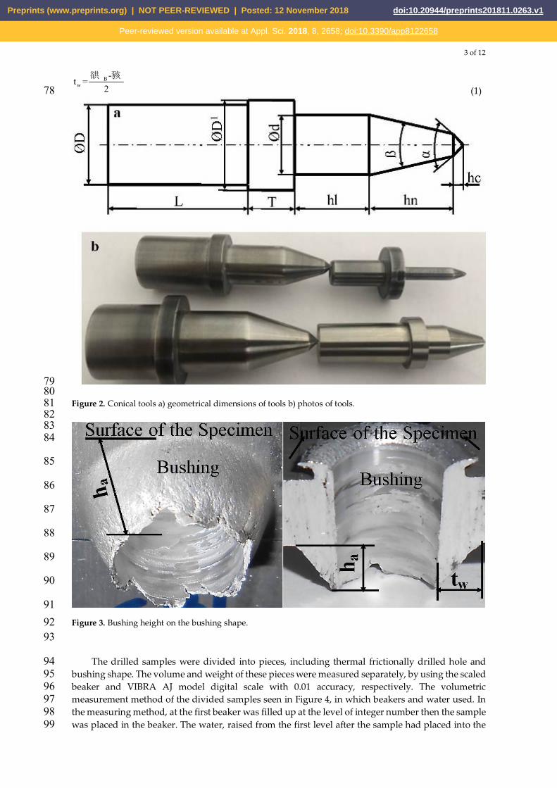
146 Figure 6. Bushing shape according to material thickness and hole diameter. 147 148
In TFD operations, it considered that the most influential parameter on the bushing geometrical 149 dimensions is material thickness. However, there are other crucial parameters, such as hole diameter, 150 spindle speed, and feed rate, affect these dimensions. Because the volume of the evacuated material 151 from the thermal frictional drilled material shapes the bushing. Therefore, the material thickness (t) 152 and hole diameter (Ød) are more influential parameters than the selected spindle speed and feed rate, 153 on the shaping of the bushings. Although the effects of spindle speed and feed rate factors on the 154 geometrical dimensions of the bushing shape are less than the material thickness and hole diameter, 155 they may cause the cracks and petal formation generations especially in TFD of brittle sheet materials, 156 due to rotating and proceeding motions of the conical tool. 157
The experimentally gained bushing shapes for different t and d values are given in Figure 6. As 158 shown from this figure that the cracks and petal formations on the bushings were increased with 159 higher d and lower (t) values. When (t) value was exceeded 6mm, cracks and petal formations were 160 almost completely eliminated under the used experimental conditions. 4 and 6 mm material 161 thicknesses were found appropriate only for hole diameters of 5 and 10 mm, according to cracks and 162 petal formations criterion, when 2 mm material thickness was not appropriate. Therefore, in the TFD 163
Preprints (www.preprints.org) | NOT PEER-REVIEWED | Posted: 12 November 2018 doi:10.20944/preprints201811.0263.v1
Peer-reviewed version available at Appl. Sci. 2018, 8, 2658; doi:10.3390/app8122658
7 of 12
of sheet materials, 2 mm in thickness, hole diameters, smaller than 5 mm, recommended being 164 selected. 165
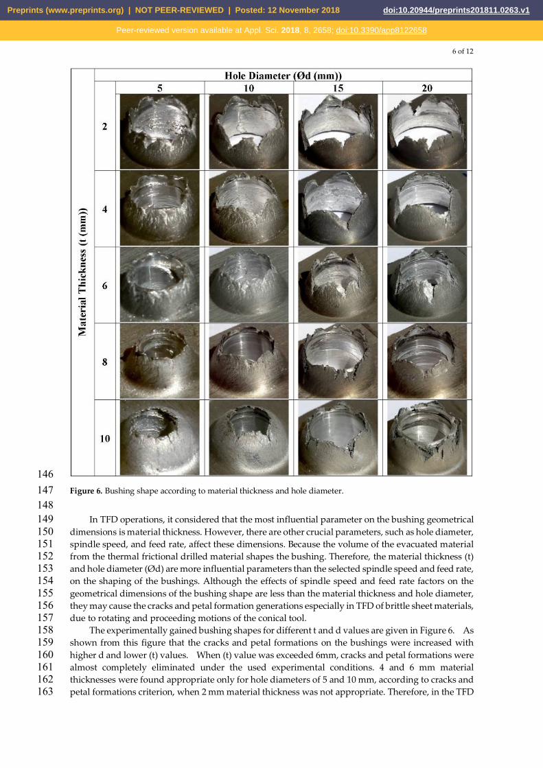
The effects of TFD parameters on the bushing height and wall thickness are given in Figure 7a-166 7d. Figure 7a tells us the bushing height is tendency of increase linearly with the hole diameter for all 167 values of materials thickness. A negligible difference between 2 to 10 mm thicknesses was observed. 168 However, the bushing wall thickness showed a nonlinear alteration with changing hole diameter 169 from 5 mm to 20 mm, and material thickness from 2 mm to 10 mm, as demonstrated in Figure 7c, and 170 Figure 7d. Bushing wall thicknesses values remained constant for material thicknesses greater than 6 171 mm, at all hole diameters. However, it showed a linear changing for 2, 4, and 6 mm thickness, at 172 selected 5, 10, and 15 mm hole diameters. Contrary to the literature, bushing height and wall 173 thickness dimensions increased nonlinearly with stepping up the material thickness, also bushing 174 height is not equal to 2 -3 times of the drilled material thickness. According to the graphs in Figure 7, 175 while hole diameter has a linear influential on bushing height, there is a little, negligible, effect of 176 material thickness on bushing height. 177
178
179 Figure 7. The effects of hole diameter and material thickness a) and b) on bushing height, c) and d) bushing wall. 180 181
Additionally, the effect of hole diameters and material thicknesses on bushing height and wall 182 thickness was investigated by using Minitab software, as shown in Figures 8a and 8b. The main 183 effects plots for bushing height and wall thickness can be demonstrated in Figure 8a and 8b, 184 depending on selected hole diameters, 5, 10, 15, and 20 mm, and material thicknesses, 2, 4, 6, 8, and 185
Preprints (www.preprints.org) | NOT PEER-REVIEWED | Posted: 12 November 2018 doi:10.20944/preprints201811.0263.v1
Peer-reviewed version available at Appl. Sci. 2018, 8, 2658; doi:10.3390/app8122658
8 of 12
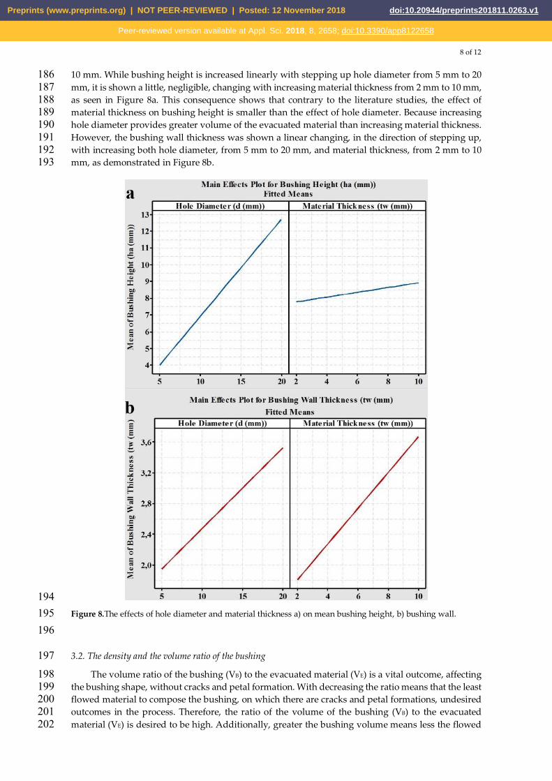
10 mm. While bushing height is increased linearly with stepping up hole diameter from 5 mm to 20 186 mm, it is shown a little, negligible, changing with increasing material thickness from 2 mm to 10 mm, 187 as seen in Figure 8a. This consequence shows that contrary to the literature studies, the effect of 188 material thickness on bushing height is smaller than the effect of hole diameter. Because increasing 189 hole diameter provides greater volume of the evacuated material than increasing material thickness. 190 However, the bushing wall thickness was shown a linear changing, in the direction of stepping up, 191 with increasing both hole diameter, from 5 mm to 20 mm, and material thickness, from 2 mm to 10 192 mm, as demonstrated in Figure 8b. 193
194 Figure 8.The effects of hole diameter and material thickness a) on mean bushing height, b) bushing wall. 195 196
3.2. The density and the volume ratio of the bushing 197
The volume ratio of the bushing (VB) to the evacuated material (VE) is a vital outcome, affecting 198 the bushing shape, without cracks and petal formation. With decreasing the ratio means that the least 199 flowed material to compose the bushing, on which there are cracks and petal formations, undesired 200 outcomes in the process. Therefore, the ratio of the volume of the bushing (VB) to the evacuated 201 material (VE) is desired to be high. Additionally, greater the bushing volume means less the flowed 202
Preprints (www.preprints.org) | NOT PEER-REVIEWED | Posted: 12 November 2018 doi:10.20944/preprints201811.0263.v1
Peer-reviewed version available at Appl. Sci. 2018, 8, 2658; doi:10.3390/app8122658

9 of 12
material composing the flake and dissipating into surroundings. Furthermore, the density of the 203 bushing is changeable, due to the drilled samples, was subjected to the deformation phenomenon, 204 causing the microstructure of the flowed material, composing bushing shape, to change. 205
According to the bushing shape and its geometrical dimensions, such as bushing height and 206 wall thickness, both the ratio of the volume of the bushing (VB) to the volume of the evacuated 207 material (VE) and the density of the bushing are vital outcomes in TFD operations, because of having 208 influential on bushing shape, desiring without cracks and petal formation. 209
210 Figure 9. The effects of hole diameter and material thickness a) on mean bushing height, b) bushing wall. 211
212 The relationship between the hole diameter (d), the material thickness (t), and the bushing 213
density (ρ), the ratio of (VB) to (VE) can demonstrated, as in Fig. 9. While the bushing density was 214 changed in small quantities, between 2.54 gr/cm3 and 2.75 g/cm3, with increasing material thickness 215 (t) and hole diameter (d), the ratio of (VB) to (VE) was substantially changed between 61% and 84 %. 216 Therefore, the density of the bushing shape changed in small and inconsiderable quantities. This 217 means that the substantial of the softened and flowed material composed the bushing shape. 218
Preprints (www.preprints.org) | NOT PEER-REVIEWED | Posted: 12 November 2018 doi:10.20944/preprints201811.0263.v1
Peer-reviewed version available at Appl. Sci. 2018, 8, 2658; doi:10.3390/app8122658
10 of 12
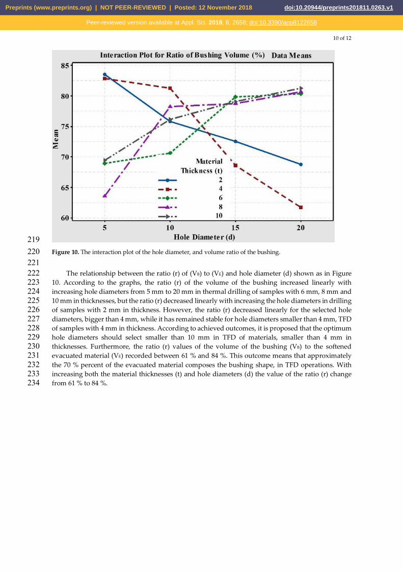
219 Figure 10. The interaction plot of the hole diameter, and volume ratio of the bushing. 220 221
The relationship between the ratio (r) of (VB) to (VE) and hole diameter (d) shown as in Figure 222 10. According to the graphs, the ratio (r) of the volume of the bushing increased linearly with 223 increasing hole diameters from 5 mm to 20 mm in thermal drilling of samples with 6 mm, 8 mm and 224 10 mm in thicknesses, but the ratio (r) decreased linearly with increasing the hole diameters in drilling 225 of samples with 2 mm in thickness. However, the ratio (r) decreased linearly for the selected hole 226 diameters, bigger than 4 mm, while it has remained stable for hole diameters smaller than 4 mm, TFD 227 of samples with 4 mm in thickness. According to achieved outcomes, it is proposed that the optimum 228 hole diameters should select smaller than 10 mm in TFD of materials, smaller than 4 mm in 229 thicknesses. Furthermore, the ratio (r) values of the volume of the bushing (VB) to the softened 230 evacuated material (VE) recorded between 61 % and 84 %. This outcome means that approximately 231 the 70 % percent of the evacuated material composes the bushing shape, in TFD operations. With 232 increasing both the material thicknesses (t) and hole diameters (d) the value of the ratio (r) change 233 from 61 % to 84 %. 234
Preprints (www.preprints.org) | NOT PEER-REVIEWED | Posted: 12 November 2018 doi:10.20944/preprints201811.0263.v1
Peer-reviewed version available at Appl. Sci. 2018, 8, 2658; doi:10.3390/app8122658

11 of 12
235 Figure 11. The interaction plot of the hole diameter, and density of the bushing. 236 237
The density values of bushings, derived from thermal friction drilling operations of A7075-T651 238 aluminum alloys, 2, 4, 6, 8, and 10 mm in thicknesses, changed from 2.54 g/ cm3 to 2.75 g/ cm3, while 239 the density of the selected samples was 2.7 g/ cm3. Although the density of the samples with 4 mm 240 and 6 mm in thicknesses showed different values from the other selected samples, the density of the 241 bushing was changed in small and inconsiderable quantity, as seen in Figure 11. Depending on the 242 results, the density of the bushing shape demonstrated inconsiderable alteration, in TFD operations. 243 244 4. Conclusions 245
The bushing shape, especially the softened flowed material, composing the bushing shape, was 246 affected by material thickness and hole diameter, together with tool geometrical dimensions, feed 247 rate and spindle speed. Particularly, material thickness and hole diameter are the most crucial 248 parameters on composing the bushing shape and its geometrical dimensions. Because the material 249 quantity of the softened and flowed material, evacuated from the TFD sample, increases at selected 250 high diameters followed by material thicknesses. The spindle speeds and feed rates provide the 251 rotating and proceeding motions of the conical tool during the process, causing cracks and petal 252 formation on the bushing shapes. Furthermore, the bushing height and wall thickness were altered 253 by the material thickness and hole diameter linearly. Contrary to the literature, the bushing height 254 values were not equal to be approximately 2-3 times of the TFD material. In the end, it was 255 investigated that the bushing height and wall thickness values were increased linearly with 256 increasing both material thickness and hole diameter, but the effect of the hole diameter was bigger 257 than the material thickness. 258
The changing in the density of the bushing recorded in small and inconsiderable quantity. These 259 values were around 2.7 g/cm3, the density of A7075-T651 aluminum alloy. The ratio (r) of the volume 260 of the bushing (VB) to the volume of the evacuated material (VE) was changed about from 61 % to 84 261 % percentages. According to the recorded values, the volume ratio of the bushing (r) is accepted to 262 be approximately 70 %, especially, between 70 % and 75 % percentages. 263
Preprints (www.preprints.org) | NOT PEER-REVIEWED | Posted: 12 November 2018 doi:10.20944/preprints201811.0263.v1
Peer-reviewed version available at Appl. Sci. 2018, 8, 2658; doi:10.3390/app8122658

12 of 12
Author Contributions: All authors provided individual contributions at the researching, analyzing, 264 investigating, and preparing procedure of the paper. 265 Funding: This research received no external funding. 266 Acknowledgments: This paper was not supported by anyone, except the authors of the paper. 267 Conflicts of Interest: The authors declare no conflict of interest. 268 269 References 270 1. Eliseev, A. A. Fortuna, S. V. Kolubaev, E. A. Kalashnikova, T. A. Microstructure modification of 2024 271
aluminum alloy produced by friction drilling. Mater. Sci. Eng. (2017), 691, 121-25. 272 https://doi.org/10.1016/j.msea.2017.03.040 273
2. Demir, Z. Özek, C. Investigate the effect of pre-drilling in friction drilling of A7075-T651. Mater. Manuf. 274 Proc. (2014), 29, 593-599. http://dx.doi.org/10.1080/10426914.2014.892986 275
3. El-Bahloul, S. A. El-Shourbagy, H. E. El-Bahloul, A. M. El-Midany, T. T. Experimental and thermo-276 mechanical modeling optimization of thermal friction drilling for AISI 304 Stainless steel. CIRP J. Manuf. 277 Sci. Technol. (2018), 20, 84-92. https://doi.org/10.1016/j.cirpj.2017.10.001 278
4. Van Geffen, J. A. Rotatable piercing tools for forming bossed holes USA. Patent 4.185.486. (1980), 279 5. Miller, S. F. Li, R. Wang, H. Shih, A. J. Experimental and numerical analysis of the friction drilling process. 280
J. Manuf. Sci. Eng. (2006), 128, 802-810. DOI: 10.1115/1.2193554 281 6. Lee, S. M. Chow, H. M. Huang, F. Y. Yan, B. H. Friction drilling of austenitic stainless steel by uncoated 282
and PVD AlCrN- and TiAlN-coated tungsten carbide tools. Int. J. Mach. Tools Manuf. (2009), 49, 81-88. 283 7. Özek, C. Demir, Z. Investigate the Surface Roughness and Bushing Shape in Friction Drilling of A7075-T651 284
and St 37 Steel. TEM J. (2013), 2 (2), 170-180. 285 8. Demir, Z. Özek, C. Investigation of the bushing height and wall thickness in friction drilling of A7075-t651 286
alloy with and without hole. Nation. Mach. Manuf. Symp. Bursa, Turkey, 2014, 23-25 287 9. Özek, C. Demir, Z. Investigate of the effect of experimental parameters on the friction drilling of a7075-t651 288
aluminum alloy. Firat Univ. J. Eng. (2013), 25(1), 39-47. 289 10. Kaya, M. T. Aktas, A. Beylergil, B. Akyildiz, H. K. An experimental study on friction drilling of st12 steel. 290
Trans. Can. Soc. Mech. Eng. (2014), 38(3), 319-329. 291 11. Özek, C. Demir, Z. Bushing height according to material thickness. Dicle Univ. J. Eng. (2013), 4(2), 61-67. 292 12. Raju, B. P. Swamy, M. K. Finite element simulation of a friction drilling process using deform 3D. Int. J. 293
Eng. Res. Applica. (IJERA), (2012), 2, 716 – 721. 294 13. Ku, W. L. Hung, C. L. Lee, S. M. Chow, H. M. Optimization in thermal friction drilling for SUS 304 295
stainless steel. Int. J. Adv. Manuf. Technol. (2011), 53, 935-944. 296 14. Miller, S. F. Tao, J. Shih, A. J. Friction drilling of cast metals. Int. J. Mach. Tools Manuf. (2006), 46, 1526-1535. 297
doi:10.1016/j.ijmachtools.2005.09.003 298 15. Miller, S. F. Blau, P. T. Shih, A. J. Microstructural alterations associated with friction drilling of steel, 299
aluminum, and titanium. J. Mater. Eng. Perform. (2007), 14(5), 647-653. doi:10.1361/105994905X64558 300
Preprints (www.preprints.org) | NOT PEER-REVIEWED | Posted: 12 November 2018 doi:10.20944/preprints201811.0263.v1
Peer-reviewed version available at Appl. Sci. 2018, 8, 2658; doi:10.3390/app8122658