An Experimental Investigation Into Corrossion Problems At ...
18
Page 44 www.ijiras.com | Email: [email protected] International Journal of Innovative Research and Advanced Studies (IJIRAS) Volume 6 Issue 1, January 2019 ISSN: 2394-4404 An Experimental Investigation Into Corrossion Problems At Kaduna Refinery And Petrochemicals Plant Kaduna, Nigeria, Using Local Crude Oil Blend Engr. Shadrack Ogonda Mbata Department of Petroleum Engineering, Faculty of Engineering, University of Port Harcourt, Nigeria I. INTRODUCTION A. BACKGROUND OF STUDY Petroleum refining has evolved continuously in response to changing consumer demand for better and different products. Refining is the processing of the complex mixture of hydrocarbons into a number of other complex mixtures of hydrocarbons. The original requirement was to produce kerosene as a cheaper and better source of light. The development of the internal combustion engine led to the production of gasoline and diesel fuels, the evolution of the airplane created a need first for high-octane aviation gasoline and then for fuel, a sophisticated form of the original product, kerosene. Present day refineries produce a variety of products, including many required as feedstock for the petrochemical industry, and asphalts for road construction etc. which gave rise to the construction of Kaduna Refinery and Petrochemical Company in the northern part of the country (Nigeria). Abstract: Corrosion problem in Refinery operation has led to serious economic waste. The Kaduna Refinery and Petrochemical Company Limited is one of the four Refineries established by the Federal Government of Nigeria through the Nigerian National Petroleum Co-operation (NNPC). The Kaduna Refinery from its inception was designed to process heavy crude oil for the production of lubricants and since the Nigerian crude oil are in the majority of cases light, importation of the crude from abroad was the only option. Recent research on blending of crude from different fields in Nigeria to achieve the same characteristics as the imported crude has given some positive results. Then there is need to investigate the corrosiveness of the blend to ensure a trouble free operation during the trail run. Samples from various oil fields in Nigeria were blended which formed medium A, and an inhibitor was added to the blend to form medium B, and finally Arabian light was obtained from NNPC (Department of Petroleum Resources), which formed medium C, a coupon of 40mm made of 5Cr. ½ Mo was prepared (six in number). The coupons were tested in the different media for corrosion effect under varying temperature of the range of 230 o C – 400 o C; prolonged effect on the coupon was also observed. From the analysis of the observation, it was noted that the corrosion rate of the Nigerian crude blend increased slightly with temperature in steps of 230 o C up to 400 o C and 480 o C maximum in some cases. A comparative analysis between the corrosion rates measured by medium A and B at the same temperature limit indicated a reduction in corrosion rate in favor of Medium B. the corrosion rate measured by medium C is higher than that of medium B. Hence, from the experimental analysis, it was deduced that blending Nigerian local crude oil to achieve the desired characteristics of the imported crude to feed the aforesaid plant was economically feasible and sustainable. Keywords: Background of Study, Literature Review, Experimental Estimation of Corrosion Rate, Results, Analysis and Discussion, Summary, Conclusion and Recommendations.
Transcript of An Experimental Investigation Into Corrossion Problems At ...
Page 44 www.ijiras.com | Email: [email protected]
International Journal of Innovative Research and Advanced Studies (IJIRAS)
Volume 6 Issue 1, January 2019
ISSN: 2394-4404
An Experimental Investigation Into Corrossion Problems At
Kaduna Refinery And Petrochemicals Plant Kaduna, Nigeria,
Using Local Crude Oil Blend
Engr. Shadrack Ogonda Mbata
Department of Petroleum Engineering, Faculty of Engineering,
University of Port Harcourt, Nigeria
I. INTRODUCTION
A. BACKGROUND OF STUDY
Petroleum refining has evolved continuously in response
to changing consumer demand for better and different
products. Refining is the processing of the complex mixture of
hydrocarbons into a number of other complex mixtures of
hydrocarbons. The original requirement was to produce
kerosene as a cheaper and better source of light.
The development of the internal combustion engine led to
the production of gasoline and diesel fuels, the evolution of
the airplane created a need first for high-octane aviation
gasoline and then for fuel, a sophisticated form of the original
product, kerosene. Present day refineries produce a variety of
products, including many required as feedstock for the
petrochemical industry, and asphalts for road construction etc.
which gave rise to the construction of Kaduna Refinery and
Petrochemical Company in the northern part of the country
(Nigeria).
Abstract: Corrosion problem in Refinery operation has led to serious economic waste. The Kaduna Refinery and
Petrochemical Company Limited is one of the four Refineries established by the Federal Government of Nigeria through
the Nigerian National Petroleum Co-operation (NNPC). The Kaduna Refinery from its inception was designed to process
heavy crude oil for the production of lubricants and since the Nigerian crude oil are in the majority of cases light,
importation of the crude from abroad was the only option. Recent research on blending of crude from different fields in
Nigeria to achieve the same characteristics as the imported crude has given some positive results. Then there is need to
investigate the corrosiveness of the blend to ensure a trouble free operation during the trail run.
Samples from various oil fields in Nigeria were blended which formed medium A, and an inhibitor was added to the
blend to form medium B, and finally Arabian light was obtained from NNPC (Department of Petroleum Resources),
which formed medium C, a coupon of 40mm made of 5Cr. ½ Mo was prepared (six in number). The coupons were tested
in the different media for corrosion effect under varying temperature of the range of 230oC – 400
oC; prolonged effect on
the coupon was also observed.
From the analysis of the observation, it was noted that the corrosion rate of the Nigerian crude blend increased
slightly with temperature in steps of 230oC up to 400
oC and 480
oC maximum in some cases.
A comparative analysis between the corrosion rates measured by medium A and B at the same temperature limit
indicated a reduction in corrosion rate in favor of Medium B. the corrosion rate measured by medium C is higher than
that of medium B. Hence, from the experimental analysis, it was deduced that blending Nigerian local crude oil to achieve
the desired characteristics of the imported crude to feed the aforesaid plant was economically feasible and sustainable.
Keywords: Background of Study, Literature Review, Experimental Estimation of Corrosion Rate, Results, Analysis
and Discussion, Summary, Conclusion and Recommendations.
Page 45 www.ijiras.com | Email: [email protected]
International Journal of Innovative Research and Advanced Studies (IJIRAS)
Volume 6 Issue 1, January 2019
ISSN: 2394-4404
The Kaduna Refinery and petrochemical Limited is one of
the four refineries established by the Government of Nigeria
through the Nigerian National Petroleum Co-operation
(NNPC). The Kaduna Refinery from its inception was
designed to process heavy crudes for the production of
lubricants and since the Nigerian crude’s are in the majority of
cases light, importation of the crude from abroad was the only
option. Recent research on blending of crudes (which is the
process of mixing and combining hydrocarbon fractions,
additives, and other components to produce finished products
with specific performance properties) from different fields in
Nigeria to achieve the same characteristics as the imported
crude has given some positive results. Then is therefore the
need to investigate the corrosiveness of the blend to ensure a
trouble free operation during the trial run or field operation.
B. STATEMENT OF THE PROBLEM
Recently, research proposals on the investigation into
corrosion problems in Kaduna Refinery and petrochemical
company (KRPC) using Nigeria crude blend have been
presented by different Engineers and Scientists, but the value
and reliability of the data to be obtained depends on details
involved in the test.
Since the refinery was designed to process heavy crudes
for the production of lubricants and since the Nigerian crude
are in the majority of cases light, important of the crude from
abroad was the only option. Recent research on blending of
crudes from different fields in Nigeria to achieve the same
characteristics as the imported crude has given some positive
results. Then, there is need to investigate the corrosiveness of
the blend to ensure a trouble free operation during the trial
run.
C. OBJECTIVE OF THE STUDY
Controlling and manipulating all the rate factors affecting
corrosion in a process plant are very difficult. Simulating
actual refinery operation in a laboratory test is of considerable
importance in obtaining reliable and reproducible results.
Therefore, the main objective of this is to design an
adequate experimental technique to carry out the following
functions:-
Determine the appropriate blend ratio to yield the
characteristics of the desired crude (imported),
To test and prove operational reliability of the blended
crude,
Determination of penetration (corrosion) rate and
estimation of probable retirement rate, by the weight loss
method,
Correlation of unexpected changes of process
environment to operation variables,
Process control, inhibition, anodic and cathodic
protection,
Material assessment and selection.
II. LITERATURE REVIEW
A. CONCEPT OF CORROSION
Corrosion is a common phenomenon in petroleum
refining environment; its effects are so detrimental that
various methods of preventing and controlling it have been put
forward by engineers.
Corrosion mechanism can be described as an
electrochemical process, as a result of observations on the
behavior of iron in aqueous media. For this process to occur,
three requirements must be fulfilled.
An electromotive force or potential difference must be
present, i.e. anode and cathode areas.
There must be an electrical or couple established between
the anode and the cathode.
The anode and cathode, electrically connected, must be in
contact with the test fluid that will conduct current (as
electrolyte).
For corrosion to occur at a significant rate, some means of
cathodic depolarization must be active. In other words, in the
absence of the cathodic depolarization agents, such as oxygen
or thermally degraded components, the system soon results in
a drastic reduction of the corrosion rate. If the corrosion
continues and more metal loss is evident, an effective cathodic
depolarization mechanism is present.
The electrochemical phenomena of corrosion can be
discussed as follows: On the system vessel, there is an anode
and a cathode; the metal at the anode loses two electrons
which flows through the metal pipe to the cathode. The
surface reaction is as follows:
Fe Fe++
+ 2e ----------------------------------2.1.1
The rate of this reaction is found to be dependent upon the
rate of the cathode reaction; hence, the corrosion rate is
“cathodically controlled”. The iron ion, Fe++
, enters the
solution as a positively charged soluble particle of ion. The
cathode, being negatively charged, attracts hydrogen ions (H+)
which arise from the dissociation or ionization of water.
H2O H+ + OH
- -----------------------2.1.2
At the cathode, hydrogen ions accept electrons and
become atom of hydrogen.
2H+ + 2e 2H -------------------------------2.1.3
Since the electrolyte must remain electrically neutral, the
positively charged ferrous ions (Fe++
) often are oxidized to
ferric ions (Fe+++
) which react with the negatively charged
hydroxyl ions to form ferric hydroxide or rust.
Fe++
+ 3H2O Fe+++
+ 3OH Fe (OH)3 rust + 3H+--2.1.4
If enough hydrogen accumulates at the cathode, it
becomes polarized; i.e. a very thin film of hydrogen will cover
the metal surface which prevents direct contact between the
electrons and the cathode. It behaves as a non-ferrous coating
membrane. The corrosion severity is a function of the
membrane permeability.
a. CHEMICAL THEORY
The chemical corrosion mechanism is one of the
corrosion processes which depend on the nature of the
surrounding media with which the metal reacts. Corrosion at
high temperature in the vapor and gaseous phase and corrosion
Page 46 www.ijiras.com | Email: [email protected]
International Journal of Innovative Research and Advanced Studies (IJIRAS)
Volume 6 Issue 1, January 2019
ISSN: 2394-4404
in liquids (non-electrolytes are classified as chemical
corrosion).
Examples of gaseous corrosion are corrosion of furnace
structures, some parts of internal combustion engines, steam
and gas turbine blades, oxidation of metals on heating, etc.
The rate of gaseous corrosion is affected considerably by the
composition of the corroding medium. An example of non-
electrolytic corrosion is attack in liquids, which are non
conductors of electric current (e.g. in various organic liquids,
in alcohol, benzene, etc).
Refinery metals are not homogenous, but contain
inclusions, precipitates and perhaps several different phases.
The phenomenon of chemical corrosion is clearly explained as
the loss of material due to chemical attack. It can also be
described as the destructive attack of a metal by chemical
reaction with its environment.
Generally, it occurs when a metal reacts with its
environment and invariably followed by a loss of mass and
weight by the metal. Corrosion may be classified into two
types namely – the uniform and localized types of corrosion.
B. UNIFORM CORROSION
This is the most common type of corrosion. It is normally
characterized by a chemical reaction, which proceeds
uniformly over the entire exposed surface. The metal becomes
thinner and eventually fails. Oxygen corrosion called rusting
is a common type. Oxygen is more corrosive in salt water than
in fresh water. The dissolved oxygen (DO) is the major cause
of vessel corrosion.
Oxygen can cause severe corrosion at very low
concentration, (less than 1ppm). If carbon (IV) oxide or
hydrogen sulphide is dissolved in oxygen-contaminated crude,
the corrosiveness is increased drastically. This type of
corrosion can be prevented or reduced by the use of proper
materials, coatings, inhibitors or cathodic protection.
C. LOCALIZED CORROSION
This is the type of corrosion that is being observed at the
specific portions of the metal. It is the most difficult form of
corrosion to be detected in the oil industry. Its attack takes
several forms which include: galvanic, crevice, stress
cracking, pitting, fatigue, selective leaching, fretting,
electrolytic and erosion corrosion.
a. GALVANIC CORROSION
When two different metals are placed in contact in an
electrolyte, the corrosion rate of the more reactive metal will
usually increase and the corrosion rate of the less reactive
metal will decrease. This principle is utilized in a beneficial
way in cathodic protection. Steel is connected to a more
reactive metal such as magnesium and is being protected from
such corrosion. Accelerated corrosion due to galvanic effects
is usually observed at the junction of the two metals. For
instance, when new pipe is connected to old pipe, the new pipe
acts as the anode and corrodes preferentially.
This type of localized corrosion can be prevented by
proper welding practices, insulating metals from each other,
keeping dissimilar metals apart and using metals that are
relatively close together in the galvanic series.
b. CREVICE CORROSION
Crevices promote the formation of concentration cells.
This is especially serious in oxygenated systems where the
oxygen in the crevice may be consumed more rapidly than
fresh oxygen can diffuse into the crevice. This causes the pH
in the crevice to decrease, resulting in a more acidic
environment, which accelerates corrosion.
c. STRESS CRACKING
This type of localized corrosion includes any combined
effect of stress and corrosion on the behavior of the metal
which leads to accelerated attack and cracking in some
refinery metal, especially in the cyclic pipe networks that are
difficult to avoid because of the complicated nature of
Refinery systems.
Although, the mechanism of stress cracking is not
completely understood, it is generally accepted that, the
following conditions must be present before it can occur:
Hydrogen sulphide (H2S),
Water: Even a trace amount of moisture is sufficient,
High strength steel: The exact strength level varies with
the composition and microstructure of the steel,
The steel must be under tensile stress or load.
The materials for application in the environment
containing hydrogen sulphide (H2S), Sulphur (IV) (SO2)
should be selected according to NACE standing MR 01-75
(latest revision).
d. PITTING CORROSION
This type of localized corrosion is characterized by the
appearance of pit-like spot over the surface of the metal. It is
caused by the presence of non-uniform conditions, such as low
pH values of the immediate environment and its differential
aeration. It is common with Aluminum and stainless steel in
aqueous surroundings. Addition of sodium or potassium
dichromate inhibits its effects.
e. FATIGUE CORROSION
This is the result of cyclic stress and corrosion. Most
sucker breaks and transmission failures occur as a result of
corrosion fatigue. It can also be the cause of pump failures. It
is possible on any part that is subjected to a cyclic stress in a
corrosive environment. It is a brittle type of failure which can
occur at stress levels well below the yield strength.
f. FRETTING
This localized corrosion occurs when two metal surfaces
are in contact with each other in a corrosive environment and
are subjected to one vibration or the other relative to the
motion. Accelerated attack results from the continuous
removal of any protective films from the metal surfaces. It
occurs mainly on machine parts such as ball and roller
Page 47 www.ijiras.com | Email: [email protected]
International Journal of Innovative Research and Advanced Studies (IJIRAS)
Volume 6 Issue 1, January 2019
ISSN: 2394-4404
bearings, shafts and gears. This type of corrosive can be
prevented by proper welding practices and insulating the
metals.
g. EROSION CORROSION AND IMPINGEMENT
The formation of a layer of corrosion product on the
surface of a corroding metal usually results in decreased
corrosion rates. The corrosion product acts as an insulator and
partially protects the surface.
The removal of the corrosion product by erosion due to
high velocities, turbulence or the abrasive action of suspended
solids can result in increased corrosion rates by continually
exposing fresh metal to the electrolyte.
Other phenomenon similar to erosion is impingement.
This occurs when a stream impinges upon a metal surface and
breaks down protective films at very small areas resulting in
pits.
h. INTERGRANULAR CORROSION
The components of alloys are not evenly distributed
throughout the entire piece of the metal due to the effects of
the heat-treating and other chemical processes that were
involved during their productions.
This problem can be prevented by proper welding
practices, addition of columbium or titanium and use of low
carbon grades of stainless steel.
D. FACTORS AFFECTING CORROSION RATE
Various factors that can affect the rate of corrosion are:
water, acid, gases, dissimilar metals, chloride content, high
fluid velocity, air (oxygen), temperature and pressure.
a. WATER
This is the most common factor that affects corrosion in
any environment. Its content in the untreated oil varies from
0.01% - 80%. It may be in the form of oil brine, water spray,
vapor or condensate. Corrosiveness decreases with decreasing
amount of free water. But in salt water (brine), it increases.
b. ACID GASES
Carbon (IV) oxide, hydrogen sulphide and Sulphur (IV)
oxide are acid gases, which in solution decreases the pH of the
solution and therefore promotes corrosion process. At a
higher temperature, Carbon (IV) oxide helps in the formation
of a protective carbonate film on steel. Hydrogen sulphide
also forms a protective sulphide film that reduces carbon (IV)
oxide corrosion at low temperature.
The partial pressure ratio of the gases CO2/H2S indicates
the prevalent corrosion mechanism. Values greater than 200
indicate CO2 corrosion, while those less than 200 indicate H2S.
c. DISSIMILAR METALS
When metals that are far apart in the galvanic series are in
contact, they allow the flow of current in between them and
this promotes the corrosiveness of the metals.
d. CHLORIDE CONTENT
Chloride ions in crudes bearing water promotes the
breakdown of normal protective films and encourages
localized corrosion of the metal in contact. At high
concentration, they affect the solubility of the inhibitors.
e. HIGH FLUID VELOCITY
High fluid velocity or turbulence is capable of producing
shear stress in metals that can remove corrosion preventing
films. Various flow regimes can either promote or hinder
inhibitors.
f. AIR (OXYGEN)
The dissolved oxygen in the crude oil is the major cause
of corrosion in process system. This gas at low concentration
causes severe corrosion.
Oxygen is more soluble in fresh water than in salt water.
It accelerates corrosion because it is a very effective oxidizing
agent.
g. TEMPERATURE AND PRESSURE
Increased pressure normally results in increase in the
solubility of dissolved gases. Increase in solubility thereby
causes faster corrosion of metal. It can therefore be said that
increases in pressure of a system subsequently results in
increase in corrosiveness of the solution.
The corrosion rate is twice its original in every 100C rise
in temperature. This happens especially in closed systems. For
systems open to the atmosphere, corrosion rate may increase
initially with rise in temperature but at higher temperature,
dissolved gases begin to escape and so the corrosiveness of the
solution decreases.
E. BASICS OF BLENDING OPERATION
Petroleum blending operation is the process of mixing and
combining hydrocarbon fractions, additives and other
components to produce finished products with specific
performance properties. Mixed based crudes have varying
amounts of each type of hydrocarbon. Refinery crude base
stocks usually consist of mixtures of two or more different
crude oils.
The Hendrix group inc. Refining Company, Texas
defined crude oils in terms of API (American Petroleum
Institute) gravity, the higher the API gravity, The lighter the
crude. For example, light crude oils have high API gravity and
low specific gravity. Crude oils with low carbon, high
hydrogen, and high API gravity are usually rich in paraffin
and tend to yield greater proportions of gasoline and light
Page 48 www.ijiras.com | Email: [email protected]
International Journal of Innovative Research and Advanced Studies (IJIRAS)
Volume 6 Issue 1, January 2019
ISSN: 2394-4404
petroleum products; those with high carbon, low hydrogen,
and low API gravity are usually rich in aromatics.
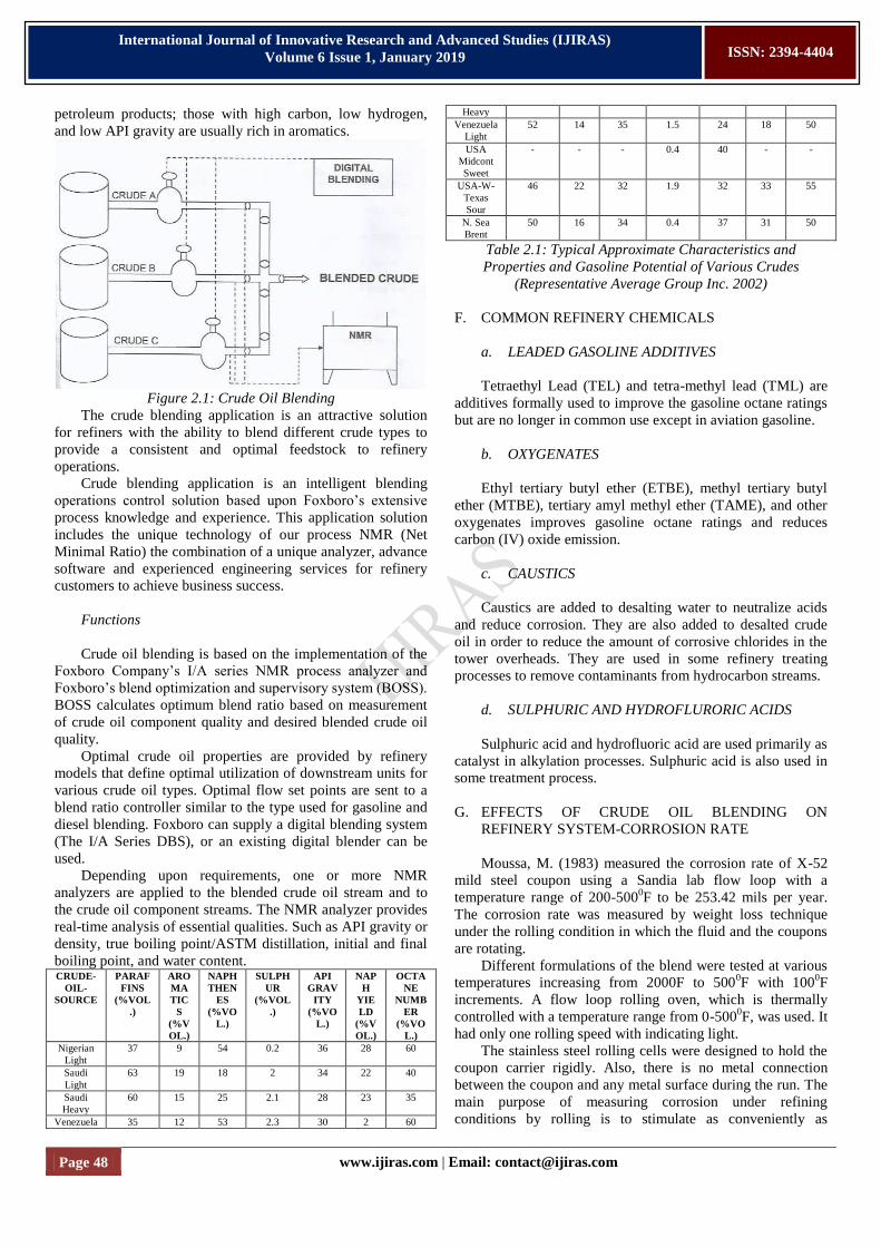
Figure 2.1: Crude Oil Blending
The crude blending application is an attractive solution
for refiners with the ability to blend different crude types to
provide a consistent and optimal feedstock to refinery
operations.
Crude blending application is an intelligent blending
operations control solution based upon Foxboro’s extensive
process knowledge and experience. This application solution
includes the unique technology of our process NMR (Net
Minimal Ratio) the combination of a unique analyzer, advance
software and experienced engineering services for refinery
customers to achieve business success.
Functions
Crude oil blending is based on the implementation of the
Foxboro Company’s I/A series NMR process analyzer and
Foxboro’s blend optimization and supervisory system (BOSS).
BOSS calculates optimum blend ratio based on measurement
of crude oil component quality and desired blended crude oil
quality.
Optimal crude oil properties are provided by refinery
models that define optimal utilization of downstream units for
various crude oil types. Optimal flow set points are sent to a
blend ratio controller similar to the type used for gasoline and
diesel blending. Foxboro can supply a digital blending system
(The I/A Series DBS), or an existing digital blender can be
used.
Depending upon requirements, one or more NMR
analyzers are applied to the blended crude oil stream and to
the crude oil component streams. The NMR analyzer provides
real-time analysis of essential qualities. Such as API gravity or
density, true boiling point/ASTM distillation, initial and final
boiling point, and water content. CRUDE-
OIL-
SOURCE
PARAF
FINS
(%VOL
.)
ARO
MA
TIC
S
(%V
OL.)
NAPH
THEN
ES
(%VO
L.)
SULPH
UR
(%VOL
.)
API
GRAV
ITY
(%VO
L.)
NAP
H
YIE
LD
(%V
OL.)
OCTA
NE
NUMB
ER
(%VO
L.)
Nigerian
Light
37 9 54 0.2 36 28 60
Saudi
Light
63 19 18 2 34 22 40
Saudi
Heavy
60 15 25 2.1 28 23 35
Venezuela 35 12 53 2.3 30 2 60
Heavy
Venezuela
Light
52 14 35 1.5 24 18 50
USA
Midcont
Sweet
- - - 0.4 40 - -
USA-W-
Texas
Sour
46 22 32 1.9 32 33 55
N. Sea
Brent
50 16 34 0.4 37 31 50
Table 2.1: Typical Approximate Characteristics and
Properties and Gasoline Potential of Various Crudes
(Representative Average Group Inc. 2002)
F. COMMON REFINERY CHEMICALS
a. LEADED GASOLINE ADDITIVES
Tetraethyl Lead (TEL) and tetra-methyl lead (TML) are
additives formally used to improve the gasoline octane ratings
but are no longer in common use except in aviation gasoline.
b. OXYGENATES
Ethyl tertiary butyl ether (ETBE), methyl tertiary butyl
ether (MTBE), tertiary amyl methyl ether (TAME), and other
oxygenates improves gasoline octane ratings and reduces
carbon (IV) oxide emission.
c. CAUSTICS
Caustics are added to desalting water to neutralize acids
and reduce corrosion. They are also added to desalted crude
oil in order to reduce the amount of corrosive chlorides in the
tower overheads. They are used in some refinery treating
processes to remove contaminants from hydrocarbon streams.
d. SULPHURIC AND HYDROFLURORIC ACIDS
Sulphuric acid and hydrofluoric acid are used primarily as
catalyst in alkylation processes. Sulphuric acid is also used in
some treatment process.
G. EFFECTS OF CRUDE OIL BLENDING ON
REFINERY SYSTEM-CORROSION RATE
Moussa, M. (1983) measured the corrosion rate of X-52
mild steel coupon using a Sandia lab flow loop with a
temperature range of 200-5000F to be 253.42 mils per year.
The corrosion rate was measured by weight loss technique
under the rolling condition in which the fluid and the coupons
are rotating.
Different formulations of the blend were tested at various
temperatures increasing from 2000F to 5000F with 100
0F
increments. A flow loop rolling oven, which is thermally
controlled with a temperature range from 0-5000F, was used. It
had only one rolling speed with indicating light.
The stainless steel rolling cells were designed to hold the
coupon carrier rigidly. Also, there is no metal connection
between the coupon and any metal surface during the run. The
main purpose of measuring corrosion under refining
conditions by rolling is to stimulate as conveniently as
Page 49 www.ijiras.com | Email: [email protected]
International Journal of Innovative Research and Advanced Studies (IJIRAS)
Volume 6 Issue 1, January 2019
ISSN: 2394-4404
possible, the rotational motion of crude at operating condition.
Based on the measured corrosion rates, he presented the
following equations to calculate the uniform corrosion rates:
The corrosion rate in mils per years as:
MPY =
…… 2.5.1
The mild steel coupons used in the study have a specific
gravity equal to 7.86g/cm3; thus this formula may be reduced
to:
MPY = ……… 2.5.2
The corrosion rate in Kilograms per square meter per
year:
Kg/m2/yr = x x
= ……………. 2.5.3
Kg/m2/yr = ……. 2.5.4
The corrosion rate in pounds per square foot per year:
Ib/ft2/Yr = x x
= ……………. 2.5.5
H. CORROSION CONTROL
Corrosion control involves the scientific measures taken
by the corrosion engineers in reducing the tremendous effects
of corrosion in the oil and gas industries. The measures
include:
a. PLACING A BARRIER BETWEEN THE METAL
AND ITS ENVIRONMENT
This is done by coating, application of chemical inhibition
and cathodic protection of the metal against the effects of
corrosion. Coating can be organic, cementing, or metallic in
nature. The most widely used industrial coatings are the coal
tar epoxies (fused epoxy, modified epoxy, epoxy-polyamide
etc.)
The principle of cathodic protection is to convert the
whole metal surface into a cathode. It is accomplished by
forcing sufficient current to flow to the structure which has to
be protected, so that there will be no flow of current from any
point on the metal surface. Chemical inhibition involves the
introducing of anti corrosion chemicals such as Sodium
Sulphide (Na2SO3), Sodium bi-sulphide (NaHSO3) etc, to the
surface of the metal in order to reduce the effect of corrosion.
b. CHANGING THE USE OR WORN-OUT METAL
This is done by changing or replacing the metal that has
lost its metallic characteristics due to its long year installation.
This is easily carried out through visual inspection of the
metals.
c. CHANGING THE ENVIRONMENT OF THE METAL
This method is effected by reducing the temperature
around the metal to an optimal range depending on the
corrosion source. For CO2 caused corrosion, temperature of
600C and above retard corrosion, whereas for H2S caused
corrosion, temperature of 600C promotes it.
Increasing the pH around the metal, removing dissolved
gases, application of biocides, gas stripping and vacuum de-
aeration are other means of controlling corrosiveness of metal
in an environment.
The selection of the method or combination of methods to
be used in controlling the corrosiveness in process plant is a
dependent factor of cost effectiveness. This means that when
applying any of the methods, you must consider the cost of the
material, labor and present economic value of the firm, as it
helps the firm to maintain its production efficiency.
I. HAZARDS OF CORROSION
The following are possible hazards caused by corrosion if
not properly controlled:
a. PLANT SHUT DOWN
Most times, plants are shut down and the operation in
some reactions of a process plant suspended because of
unexpected operational failures due to corrosion.
Monitoring of a process plant therefore is helpful in
preventing unexpected plant failure and eventual process shut
down.
b. LOSS OF VALUABLE PRODUCTS
Corrosion also leads to the loss of valuable products such
as pipeline leakage in and out of the industry. The leakage can
lead to pollution of the environment especially the aquatic life
and farmland.
c. SAFETY AND RELIABILITY
Corrosion can expose personnel’s in the plant to risk of
pollution by some dangerous pollutants that is released due to
leakage of the vessels, as if this happens, safety and reliability
is not guaranteed.
d. CONTAMINATION OF PRODUCTS
In most cases, the utility as well as market value of the
product is directly related to its price and quality. For
example, the caustics used as catalyst in refinery treating
process can be contaminated by the corroded vessel.
e. MAINTENANCE AND OPERATING COST
Corrosion effect will create difficulties in the maintenance
of metallic equipment used in various constructions. In the
manufacturing and process industries, corrosion could lead to
total failure of some unit leading generally to the collapse of
the entire plant. For such to be maintained, then money that
2
2
2
Page 50 www.ijiras.com | Email: [email protected]
International Journal of Innovative Research and Advanced Studies (IJIRAS)
Volume 6 Issue 1, January 2019
ISSN: 2394-4404
could have been used for valuable things has to sink into this
area.
Based on the measured corrosion rates and its effects, the
following equation can be used to predict “worse case”
uniform corrosion rates.
LogR = 8.78 - – 5.55X10⁻³
t+0.67LogPCO2…2.71
Where:
R = Maximum uniform corrosion rate (mils/yr)
t = temperature (OC)
PCO2 = Partial pressure of CO2 (psi)
Another corrosion rate that is widely used in the oil
industry is stated below:
Corrosion rate (R)= 365000 ……………. 2.7.2
Where:
R = Corrosion rate (mils/yr)
W = Weight loss, (g)
A = Coupon surface area, (in2)
D = Metal density, (g/in3)
T = Exposure time, (days)
J. REFINERY MATERIALS
a. CHROMIUM AND CHROMIUM ALLOYS
Chromium with atomic number 24 belongs to Group VI
in the periodic table in the subgroup that contains
molybdenum and tungsten, it is between Vanadium and
Manganese horizontally, it shows a valence of 21, 3+ and 6
+.
Stable isotopes that have been found are 50, 52, 53 and 54.
Chromium is a blue-white, very hard metal that crystallizes in
the cubic system. Their only important source is the mineral
chromites. Vauduelin in 1797 discovered Chromium, so-called
from the Greek word “Chrome”, meaning color, because its
components are highly colored.
The first use of chromium ores (about 1800) was to make
chemicals such as chromates for leather fanning and the
production of pigments, and as refractory in 1879. It was not
until 1910 that chromium ores became metallurgically
important.
Two broad classes of chromium are available to industry:
(1) ferrochromium and (2) chromium metal. Ferrochromium
can be produced by the direct reduction of the ore. To produce
chromium metal either electrochemically or by the reduction
of chromium compounds, a chemical treatment is necessary to
remove the iron and other impurities from the slanting
material.
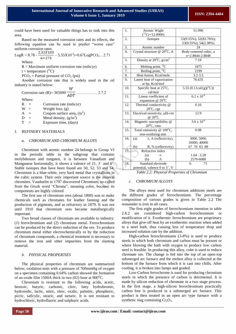
b. PHYSICAL PROPERTIES
The physical properties of chromium are summarized
below; oxidation tests with a pressure of 760mmHg of oxygen
on a specimen containing 0.04% carbon showed the formation
of an oxide film 1500A thick in two (02) hour at 9000C.
Chromium is resistant to the following acids, acetic,
benzoic, butyric, carbonic, citric, fatty hydrobromic,
hydroiodic, lactic, nitric, oleic, oxalic, palmitic, phosphoric,
picric, sallcylic, stearic, and tartaric. It is not resistant to
hydrochloric, hydrofluoric and sulphuric acids.
1. Atomic Wight
(12Cr=12.0000)
51.996
2. Isotopes 53(9.55%); 52(83.76%);
53(9.55%); 54(2.38%)
3. Atomic number 24
4. Crystal structure @ 200C, A Body-centered cubic, a
o=2.8844-2.8848
5. Density at 200C, g/cm3 7.19
6. Melting point, OC 1875
7. Boiling point, OC 2199
8. Heat fusion, Kcal/mole 3.2-3.5
9. Latent heat of vaporization
at bp, Kcal/mol
76.635
10. Specific heat at 25oC,
cal/mol
5.55 (0.11cal/(g)(oC))
11. Linear coefficient of
expansion @ 200C
6.2 x 10⁻⁶
12. Thermal conductivity @
20oC, cgs
0.16
13. Electrical resistivity, µΏ-cm
@ 200C
12.9
14. Magnetic susceptibility @
200C, cmu
3.6 x 10⁻⁶
15. Total emissivity @ 100oC,
non-oxidizing atm.
0.08
16. (a) λ, A (reflectivity),
(b) R, % (reflectivity)
3000, 5000,
10000, 40000
67 70 63 88
17. Refractive index
(a) ∞
(b) Λ
1.64 –3.28
2570-6080
18. Standard electrode
potential, valence 0 to 3+, V
0. 71
Table 2.2: Physical Properties of Chromium
c. CHROMIUM ALLOYS
The alloys most used for chromium additions steels are
the different grades of ferrochromium. The percentage
composition of various grades is given in Table 2.2 The
remainder is iron in all cases.
The first eight grades of ferrochromium intention in table
2.8.2 are considered high-carbon ferrochromium or
modification of it. Exothermic ferrochromium are proprietary
alloys that give off heat by an exothermic reaction when added
to a steel bath, thus causing less of temperature drop and
increased solution rate by the addition.
High-carbon ferrochromiums (3-8%) is used to produce
steels in which both chromium and carbon must be present or
where blowing the bath with oxygen to produce low carbon
steel is feasible. In producing this alloy, coke is used to reduce
chromate ore. The change is fed into the top of an open-top
submerged arc furnace and the molten alloy is collected at the
bottom of the furnace from which it is cast into chills. After
cooling, it is broken into lumps and graded.
Low-Carbon ferrochrome is used for producing chromium
steels in which the presence of carbon is detrimental. It is
made by silicon reduction of chromate in a two stage process.
In the first stage, a high-silicon ferrochromium practically
carbon free is produced in a submerged arc furnace. This
product is then treated in an open arc type furnace with a
synthetic slag containing Cr2O3.
Page 51 www.ijiras.com | Email: [email protected]
International Journal of Innovative Research and Advanced Studies (IJIRAS)
Volume 6 Issue 1, January 2019
ISSN: 2394-4404
However, low carbon ferrochromium can also be
produced by oxygen top blowing on high carbon metal to
reduce the carbon content; this process is said to be less costly
than the two –stage silicon reduction process. ALLOY TYPE Cr,% C,% Si,% S,% Mn%
Blocking Chrome 55-63 4-6 8-12 0.03 max
Charge Chrome 58-63 5-8 3-6 0.03 max
Charge Chrome 50-56 6-8 4-7 0.03 max
Refined Chrome 53-63 3-5 2.5
max
0.03 max
Exothermic Ferrochrome 41-51 3.6-6.4 9-14 0.03 max
Foundry Ferrochrome 55-63 4-6 8-12
“SM” Ferrochrome 60-65 4-6 4-6 4-6
High-Carbon Ferrochrome 65-70 4-7 1-3
Low-Carbon Ferrochrome 65-73 0.025-2 0.02-1
“Simplex” Low-Carbon
Ferrochrome
63-71 0.01 -
0.025
2-7
Table 2.3: Compositions of Chromium Alloys TYPE OF LOW-ALLOY STEEL AND
AVERAGE CHEMICAL CONTENT, %
DESIGNATION
Nickel – chromium steels
Ni 1.25; CrO 65
Ni 3.50; Cr 1.57 Chromium – Molybdenum steels
Cr 0.50 and 0.95; Mo 0.25, and 0.12
Nickel – Chromium – Molybdenum Steels Ni 1082; Cr 0.50 and 0.80; Mo 0.25
Ni 1.05; Cr 0.45; Mo 0.20
Ni 0. 55; Cr 0.50 and 0.65; Mo 0.20 Ni 0.55; Cr 0.50; Mo 0.12
Ni 1.00; Cr 0.80; Mo 0.25
Chromium Steels Cr 0.27, 0.40 and 0.50
Cr 0.80, 0.87, 0.90, 0.95, 1.00 and 1.05
Cr 0. 50 Cr 1.02
Cr 1.45
Chromium-Vanadium Steels Cr 0.80 and 0.95; Vo. 10 and 0.15 (min)
Boron-treated Chromium Steels
31xx
33xx
41xx
43xx
47xx
86xx 87xx
93xx
98xx
50xx
51xx 501xx
511xx
61xx
Xx13xx
Table 2.4: Basic Numbering System for Chromium Steels
K. CORROSION INHIBITORS IN PETROLEUM
REFINING
Corrosion agents in the refinery are similar to those
causing trouble in production operations, but these are
transferred to different equipment, and they are more often
concentrated. Additional difficulties are caused by higher
temperatures, pressures, and flow rates in refinery equipment
and the prohibitively high costs of downtime caused by
corrosion. Aqueous electrolytes containing acid gases such as
CO2 and H2S, mineral acids such as hydrochloric or
naphthenic acids are the principal causes of internal corrosion
in refineries. Use of neutralizing inhibitors such as sodium
hydroxide (NaOH), sodium Carbonate (Na2CO3), and
Ammonia (NH3), is much more widespread than in primary or
secondary production of petroleum. Organic inhibitors are
used extensively and often in conjunction with neutralizers.
Thus, ammonia may be used to raise the pH of an acidic liquid
to near 7.0, after which an organic inhibitor completes the job
of protection. The use of the two materials in conjunction
gives adequate protection more cheaply than does either
material alone.
III. EXPERIMENTAL ESTIMATION OF CORROSION
RATE
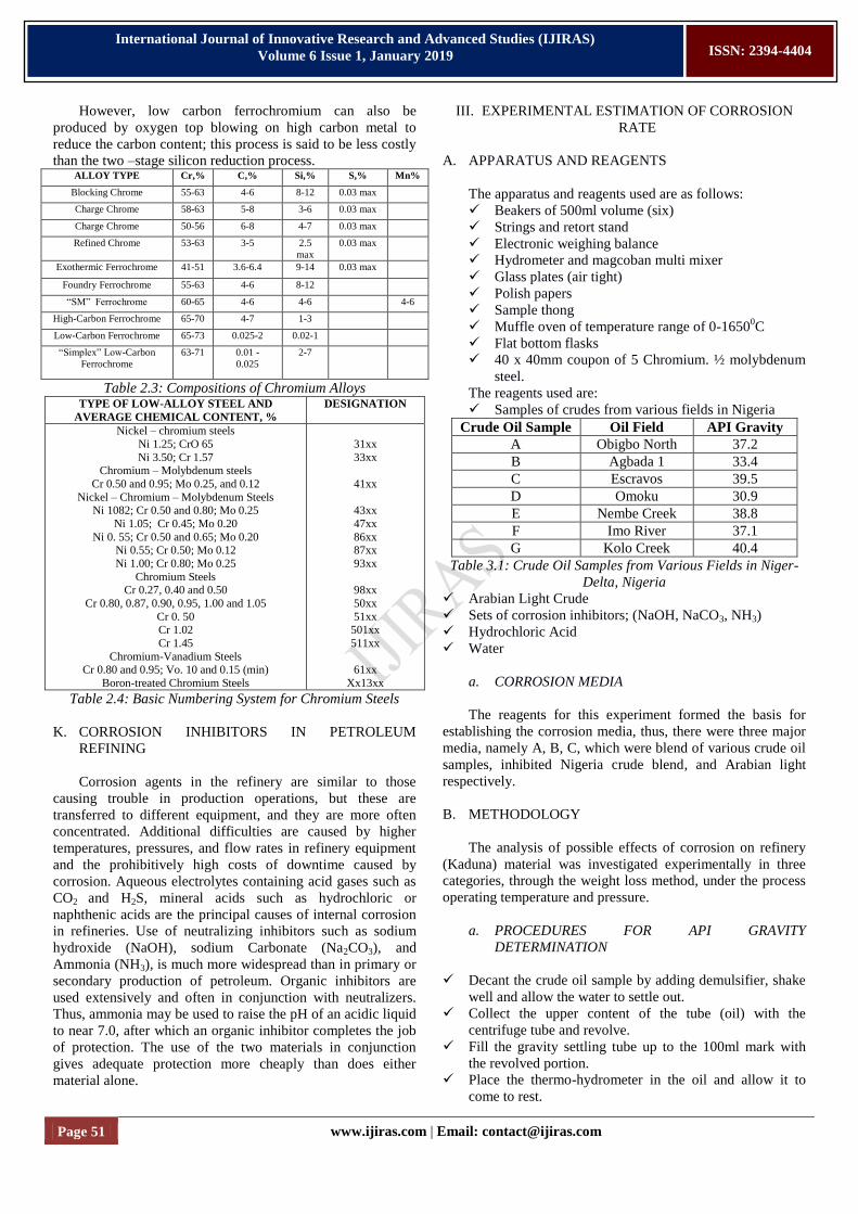
A. APPARATUS AND REAGENTS
The apparatus and reagents used are as follows:
Beakers of 500ml volume (six)
Strings and retort stand
Electronic weighing balance
Hydrometer and magcoban multi mixer
Glass plates (air tight)
Polish papers
Sample thong
Muffle oven of temperature range of 0-16500C
Flat bottom flasks
40 x 40mm coupon of 5 Chromium. ½ molybdenum
steel.
The reagents used are:
Samples of crudes from various fields in Nigeria
Crude Oil Sample Oil Field API Gravity
A Obigbo North 37.2
B Agbada 1 33.4
C Escravos 39.5
D Omoku 30.9
E Nembe Creek 38.8
F Imo River 37.1
G Kolo Creek 40.4
Table 3.1: Crude Oil Samples from Various Fields in Niger-
Delta, Nigeria
Arabian Light Crude
Sets of corrosion inhibitors; (NaOH, NaCO3, NH3)
Hydrochloric Acid
Water
a. CORROSION MEDIA
The reagents for this experiment formed the basis for
establishing the corrosion media, thus, there were three major
media, namely A, B, C, which were blend of various crude oil
samples, inhibited Nigeria crude blend, and Arabian light
respectively.
B. METHODOLOGY
The analysis of possible effects of corrosion on refinery
(Kaduna) material was investigated experimentally in three
categories, through the weight loss method, under the process
operating temperature and pressure.
a. PROCEDURES FOR API GRAVITY
DETERMINATION
Decant the crude oil sample by adding demulsifier, shake
well and allow the water to settle out.
Collect the upper content of the tube (oil) with the
centrifuge tube and revolve.
Fill the gravity settling tube up to the 100ml mark with
the revolved portion.
Place the thermo-hydrometer in the oil and allow it to
come to rest.

Page 52 www.ijiras.com | Email: [email protected]
International Journal of Innovative Research and Advanced Studies (IJIRAS)
Volume 6 Issue 1, January 2019
ISSN: 2394-4404
Read off the degree API and the corresponding
temperature to the nearest oF.
This API value is later corrected to 600F using API
correction.
CATEGORY I: CRUDE FORMULATION AND SAMPLE
PREPARATION
This category covers the preparation of various media for
this corrosion test. A trip was taken to various oil fields in
Niger Delta region of Nigeria and NNPC to obtain samples of
the materials and ratio of each component to meet specific
desirable characteristics in the required Crude A (Nigerian
Blended Crude Oil Sample).
A sample medium B (Inhibited Nigerian Blended Crude
Oil Sample), was prepared by adding an inhibitor to the blend;
and varying the concentration by 0.5g/mol and mixed very
well by the magcoban multi mixer for a period of time long
enough to ensure distribution of each component.
Some properties of the medium such as density, pH value,
Degree API were measured and recorded. Medium C (Arabian
Light Crude Oil Sample) was obtained from NNPC.
CATEGORY II: CORROSION TEST USING NIGERIA
CRUDE OIL BLEND AND INHIBITED NIGERIA CRUDE
OIL BLEND SAMPLES RESPECTIVELY
In this category, the analysis of possible effects of
Nigerian crude oil blend sample on refinery material under
operating temperature was investigated and recorded.
The coupons used were prepared by cutting out 40mm x
40mm sizes (six in number known as slots A-F) from a
chromium steel, and a hole of 2mm was bored at one end for
easier suspension in the medium. The coupon surfaces were
polished using polish papers. The coupons were thoroughly
rinsed with some distilled water. They were then dried,
weighed and dipped into the medium.
The sample alongside the medium was inserted into the
muffle oven and heated up to 230OC – 400
0C; respectively at
an interval of 300C. Corrosion rate data obtained from the test
was as a result of exposing the coupons (slots) to the medium
and varying the temperature periodically in steps of 2300C -
4000C. The time of exposure ranges from 24 – 48 hours, after
which the coupons were re-weighed and difference in weight
taken and recorded.
The experiment was evaluated for a period of six weeks.
The difference in weight comes as a result of the coupon
surface which is been cleaned with polish paper and corrosion
seats removed before re-weighing.
Note that corrosion test on both media (A&B) were
carried out simultaneously.
But since it was not possible to simulate a real industrial
operation of temperature, pressure, rotation and shearing, fluid
contamination etc. the weight loss technique was developed
and under controlled system, and the reliability of the data
obtained was dependent on the following:
The length of exposure to these fluid under the test
conditions,
The test temperature and its control,
The acidity or pH of the test fluid, and its control during
exposure time,
The composition and chemical reaction which includes
the proper choice of inhibitors and catalyst and also their
concentrations,
The conditions of immersion of the specimens inside the
crude oil media,
The surface area exposed in the bulk,
The heterogeneity of the media and the contents.
CATEGORY III: COMPARISON TEST USING THE
ARABIAN LIGHT CRUDE OIL
The method described in this study is intended primarily
to monitor the corrosion rate for the Arabian Light crude
which served as a basis for comparison and economic
evaluation. The same experimental procedure for category II
followed.
IV. RESULTS, ANALYSIS AND DISCUSSION
The results obtained from testing medium A, B and C
(Nigerian Crude oil blend, inhibited Nigerian crude oil blend
and Arabian light respectively) for the various slots (coupon
samples) are tabulated in tables 4.3, 4.4, 4.5, 4.6, 4.7 and 4.8
respectively.
Also, results obtained from the effects of temperature on
the coupons are tabulated on table 4.2, while data generated
from inhibitor evaluation are tabulated in table 4.9.
BLEND A
Crude Sample
Blend Ratio
Final 0API Gravity
Crude A Crude B Crude C
1 3 2
39.3
BLEND B
Crude Sample
Blend Ratio
Final 0API Gravity
Crude C Crude E Crude F
4 1 2
35.9
BLEND C
Crude Sample
Blend Ratio
Final 0API Gravity
Crude A Crude C Crude E
2 1 1
33.7
BLEND D
Crude Sample
Blend Ratio
Final 0API Gravity
Crude E Crude D Crude C
1 3 1
30.2
BLEND E
Crude Sample
Blend Ratio
Final 0API Gravity
Crude F Crude D Crude B
4 1 3
38.9
BLEND F
Crude Sample
Blend Ratio
Final 0API Gravity
Crude B Crude A Crude F
0 1 4
33.6
Table 4.1: Crude Oil Blend Ratios and Final API Gravity
COUPON A
Temperature Weight of Coupon (g) Weight Loss (g)
000 24.120 0.0000
230 23.921 0.1990
Page 53 www.ijiras.com | Email: [email protected]
International Journal of Innovative Research and Advanced Studies (IJIRAS)
Volume 6 Issue 1, January 2019
ISSN: 2394-4404
260 23.920 0.0010
290 23.903 0.0170
320 23.890 0.0130
350 23.739 0.1510
380 23.627 0.1120
400 23.571 0.0560
COUPON B
Temperature Weight of Coupon (g) Weight Loss (g)
000 25.399 0.000
230 25.363 0.036
260 25.349 0.014
290 25.339 0.010
320 25.302 0.037
350 25.290 0.012
380 22.242 0.048
400 22.215 0.027
COUPON C
Temperature Weight of Coupon (g) Weight Loss (g)
000 23.208 0.000
230 23.206 0.002
260 23.191 0.015
290 23.171 0.020
320 23.137 0.034
350 23.076 0.061
380 23.048 0.028
400 23.029 0.019
COUPON D
Temperature Weight of Coupon (g) Weight Loss (g)
000 23.566 0.000
230 23.140 0.426
260 22.791 0.349
290 22.577 0.214
320 22.261 0.316
350 21.824 0.437
380 21.696 0.128
400 21.265 0.431
COUPON E
Temperature Weight of Coupon (g) Weight Loss (g)
000 22.431 0.000
230 22.423 0.008
260 22.422 0.001
290 22.422 0.000
320 22.419 0.003
350 22.417 0.002
380 22.406 0.011
400 22.403 0.003
COUPON F
Temperature Weight of Coupon (g) Weight Loss (g)
000 23.238 0.000
230 23.223 0.065
260 23.208 0.015
290 23.220 0.004
320 23.207 0.013
350 23.180 0.027
380 23.134 0.046
400 23.116 0.018
Table 4.2: Effect of Temperature on the Coupons
MEDIUM A – CRUDE OIL BLEND
COUPON A
Duration
(days)ΔT
Weight of
Coupon (g)
Weight
Loss (g)Δw
Rate
Δw/Area/ΔT
(g/mm2/day)
01 23.9550 0.0000 0.000000000
03 23.9531 0.0019 0.000000593
05 23.9513 0.0018 0.000000562
07 23.9239 0.0274 0.000008562
09 23.9239 0.0140 0.000000000
11 23.9099 0.0140 0.000004375
13 23.8949 0.0150 0.000004687
15 23.8789 0.0160 0.000005000
17 23.8639 0.0150 0.000004687
19 23.8469 0.0170 0.000005312
21 23.8289 0.0180 0.000005625
COUPON B
Duration
(days)ΔT
Weight
of
Coupon
(g)
Weight
Loss
(g)Δw
Rate
Δw/Area/ΔT
(g/mm2/day)
Mean
Loss in
Weight
(g)
01 22.7940 0.0000 0.000000000 0.00000
03 22.7924 0.0016 0.000000500 0.00175
05 22.7803 0.0121 0.000003781 0.00695
07 22.7636 0.0167 0.000005218 0.01535
09 22.7458 0.0178 0.000005562 0.01560
11 22.7262 0.0196 0.000006125 0.01680
13 22.7056 0.0206 0.000006437 0.01780
15 22.6840 0.0216 0.000008343 0.01880
17 22.6573 0.0267 0.000008343 0.02085
19 22.6282 0.0291 0.000009093 0.02305
21 22.5959 0.0323 0.000010093 0.02515
Table 4.3: Corrosion Coupon: Low Alloy Steel (5cr. ½ Mo)
Concentration = 0.1M
Medium B-Inhibited Crude Oil Blend
SLOT A
Duration
(days)ΔT
Weight of
Coupon (g)
Weight
Loss (g)Δw
Rate
Δw/Area/ΔT
(g/mm2/day)
01 23.9530 0.0000 0.000000000
03 23.9390 0.0140 0.000004375
05 23.9250 0.0140 0.000004375
07 23.9080 0.0170 0.000005312
09 23.8899 0.0181 0.000005656
11 23.8706 0.0193 0.000006031
13 23.8512 0.0194 0.000006062
15 23.8313 0.0199 0.000006218
17 23.8106 0.0207 0.000006468
19 23.7895 0.0211 0.000006593
21 23.7677 0.0218 0.000006812
SLOT B
Duration
(days)ΔT
Weight
of
Coupon
(g)
Weight
Loss
(g)Δw
Rate
Δw/Area/ΔT
(g/mm2/day)
Mean
Loss in
Weight
(g)
01 22.4530 0.0000 0.000000000 0.00000
03 22.4390 0.0170 0.000005312 0.01125
05 22.4199 0.0191 0.000005968 0.01655
Page 54 www.ijiras.com | Email: [email protected]
International Journal of Innovative Research and Advanced Studies (IJIRAS)
Volume 6 Issue 1, January 2019
ISSN: 2394-4404
07 22.3943 0.0256 0.000008000 0.02130
09 22.3655 0.0288 0.000009000 0.02345
11 22.3343 0.0312 0.000009750 0.02525
13 22.2969 0.0374 0.000011687 0.02840
15 22.2566 0.0403 0.000012593 0.03010
17 22.2119 0.0447 0.000013968 0.03270
19 22.1630 0.0489 0.000015281 0.03500
21 22.1097 0.0533 0.000016656 0.03755
Table 4.4: Introduction of Corrosion Inhibitor (NaOH)
Concentration = 0.5M
SLOT A
Duration
(days)ΔT
Weight of
Coupon (g)
Weight
Loss (g)Δw
Rate
Δw/Area/ΔT
(g/mm2/day)
01 23.9290 0.0000 0.000000000
03 23.9220 0.0070 0.000002187
05 23.9143 0.0077 0.000002406
07 23.9064 0.0079 0.000002468
09 23.8979 0.0085 0.000002656
11 23.8888 0.0091 0.000002843
13 23.8793 0.0095 0.000002968
15 23.8696 0.0097 0.000003031
17 23.8590 0.0106 0.000003312
19 23.8475 0.0115 0.000003593
21 23.8351 0.0124 0.000003875
SLOT B
Duration
(days)ΔT
Weight
of
Coupon
(g)
Weight
Loss
(g)Δw
Rate
Δw/Area/ΔT
(g/mm2/day)
Mean
Loss in
Weight
(g)
01 25.3600 0.0000 0.000000000 0.00000
03 25.3530 0.0071 0.000002218 0.00705
05 25.3458 0.0072 0.000002250 0.00760
07 25.3383 0.0075 0.000002343 0.00770
09 25.3295 0.0088 0.000002750 0.00865
11 25.3502 0.0093 0.000002906 0.00920
13 25.3408 0.0094 0.000002937 0.00945
15 25.3310 0.0098 0.000003062 0.00975
17 25.3207 0.0103 0.000003218 0.01045
19 25.3093 0.0114 0.000003562 0.01145
21 25.2966 0.0127 0.000003968 0.01255
Table 4.5: Introduction of Corrosion Inhibitor (NaOH)
Concentration = 0.7M
SLOT A
Duration
(days)ΔT
Weight of
Coupon (g)
Weight
Loss (g)Δw
Rate
Δw/Area/ΔT
(g/mm2/day)
01 23.9430 0.0000 0.000000000
03 23.9369 0.0061 0.000001906
05 23.9304 0.0065 0.000002031
07 23.9235 0.0069 0.000002156
09 23.9164 0.0071 0.000002218
11 23.9090 0.0074 0.000002312
13 23.9009 0.0081 0.000002531
15 23.8922 0.0087 0.000002718
17 23.8827 0.0095 0.000002968
19 23.8728 0.0099 0.000003093
21 23.8616 0.0112 0.000003500
SLOT B
Duration
(days)ΔT
Weight
of
Coupon
(g)
Weight
Loss
(g)Δw
Rate
Δw/Area/ΔT
(g/mm2/day)
Mean
Loss in
Weight
(g)
01 25.3940 0.0000 0.000000000 0.00000
03 25.3875 0.0065 0.000002031 0.00630
05 25.3808 0.0067 0.000002093 0.00660
07 25.3739 0.0069 0.000002156 0.00690
09 25.3666 0.0073 0.000002281 0.00720
11 25.3589 0.0077 0.000002406 0.00755
13 25.3504 0.0085 0.000002656 0.00830
15 25.3419 0.0085 0.000002656 0.00860
17 25.3327 0.0092 0.000002875 0.00935
19 25.3233 0.0094 0.000002937 0.00965
21 25.3077 0.0156 0.000004875 0.0134
Table 4.6: Introduction of Corrosion Inhibitor (NaOH)
Concentration = 0.9M
SLOT A
Duration
(days)ΔT
Weight of
Coupon (g)
Weight
Loss (g)Δw
Rate
Δw/Area/ΔT
(g/mm2/day)
01 22.4600 0.0000 0.000000000
03 22.4550 0.0050 0.000001562
05 22.4596 0.0054 0.000001687
07 22.4439 0.0057 0.000001687
09 22.4380 0.0059 0.000001843
11 22.4312 0.0068 0.000002125
13 22.4244 0.0068 0.000002125
15 22.4169 0.0075 0.000002343
17 22.4090 0.0079 0.000002468
19 22.4008 0.0052 0.000001625
21 22.3922 0.0086 0.000002687
SLOT B
Duration
(days)ΔT
Weight
of
Coupon
(g)
Weight
Loss
(g)Δw
Rate
Δw/Area/ΔT
(g/mm2/day)
Mean
Loss in
Weight
(g)
01 22.7630 0.0000 0.000000000 0.00000
03 22.7579 0.0051 0.000001593 0.00505
05 22.7523 0.0056 0.00000175 0.00550
07 22.7464 0.0059 0.000001843 0.00580
09 22.7403 0.0061 0.000001906 0.00600
11 2.7339 0.0064 0.00000200 0.00660
13 22.7269 0.0070 0.000002187 0.00690
15 22.7196 0.0073 0.000002281 0.00740
17 22.7118 0.0078 0.000002437 0.00765
19 22.7037 0.0081 0.000002531 0.00815
21 22.6948 0.0089 0.000002781 0.00875
Table 4.7: Introduction of Corrosion Inhibitor (NaOH)
Medium C – Arabian Light Crude Oil
COUPON A
Duration
(days)ΔT
Weight of
Coupon (g)
Weight
Loss (g)Δw
Rate
Δw/Area/ΔT
(g/mm2/day)
01 23.9550 0.00000 0.000000000
03 23.9530 0.00020 0.000000062
05 23.9512 0.00180 0.000000562

Page 55 www.ijiras.com | Email: [email protected]
International Journal of Innovative Research and Advanced Studies (IJIRAS)
Volume 6 Issue 1, January 2019
ISSN: 2394-4404
07 23.9237 0.00275 0.000000859
09 23.9105 0.01320 0.000004125
11 23.9097 0.01180 0.000003687
13 23.8948 0.01490 0.000004656
15 23.8788 0.01610 0.000005031
17 23.8638 0.01650 0.000005156
19 23.8468 0.01730 0.000005406
21 23.8288 0.01540 0.000004812
COUPON B
Duration
(days)ΔT
Weight
of
Coupon
(g)
Weight
Loss
(g)Δw
Rate
Δw/Area/ΔT
(g/mm2/day)
Mean
Loss in
Weight
(g)
01 22.7939 0.0000 0.000000000 0.0000
03 22.7923 0.0016 0.000000005 0.0009
05 22.7802 0.0121 0.000003781 0.0070
07 22.7635 0.0167 0.000005218 0.0097
09 22.7457 0.0178 0.000005562 0.0155
11 22.7261 0.0119 0.000002718 0.0119
13 22.7055 0.0206 0.000006437 0.0178
15 22.6839 0.0216 0.000006750 0.0189
17 22.6572 0.0267 0.000008343 0.0216
19 22.6281 0.0291 0.000009093 0.0232
21 22.5958 0.0323 0.000010093 0.0239
Table 4.8: Corrosion Test with Arabian Light Crude Oil
Figure 1
Figure 2
Figure 3
Page 56 www.ijiras.com | Email: [email protected]
International Journal of Innovative Research and Advanced Studies (IJIRAS)
Volume 6 Issue 1, January 2019
ISSN: 2394-4404
Figure 4
Figure 5
Figure 6
Figure 7
Page 57 www.ijiras.com | Email: [email protected]
International Journal of Innovative Research and Advanced Studies (IJIRAS)
Volume 6 Issue 1, January 2019
ISSN: 2394-4404
Figure 8
Figure 9
Figure 10
Figure 11
Page 58 www.ijiras.com | Email: [email protected]
International Journal of Innovative Research and Advanced Studies (IJIRAS)
Volume 6 Issue 1, January 2019
ISSN: 2394-4404
Figure 12
Figure 13
A. GENERATION OF DATA
Apart from the raw data collected in terms of the
measured and weight loss recorded from the daily routine
checks, other important parameters were estimated from the
raw data.
B. PARAMETER ESTIMATION
Parameters generated from the raw data include metal loss
in weight of grams, mean loss in weight of grams and
corrosion rate.
METAL LOSS (G): The weight loss in slots A – F of
medium A, B and C were obtained by subtracting the
final weight from the initial. i.e. (W2 – W1) = ΔW … 4.1
MEAN LOSS IN WEIGHT (G): The mean loss in weight
is obtained by adding two subsequent corresponding
losses in weight and dividing by 2:
i.e w1 + w2 = ΔW …………………………………....4.2
RATE OF CORROSION (G/MM2/DAY): The rate of
corrosion is obtained by dividing the loss in weight by the
time interval.
i.e weight loss (g)x1
Area (mm2) Time (day)
= ΔW ……………………………… 4.3
A (ΔT)
PERCENTAGE INHIBITION (E). This is a measure of
effectiveness of the inhibitors for application and
economic Evaluation.
i.e E = 100(wo-w1) ………………....4.4
Wo
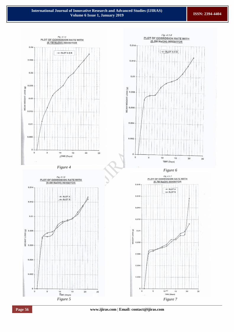
C. ANALYSIS OF RESULTS
The results obtained from testing the effects of
temperature on sample A, B and C under varying temperatures
and weekly evaluation were plotted in graphs shown in figures
4.1.1 – 4.2.8. The 4th
blend was used for medium A and B,
since it has characteristics API gravity close to that of the
Arabian Light.
The test results and its graphical trend indicate the
following:
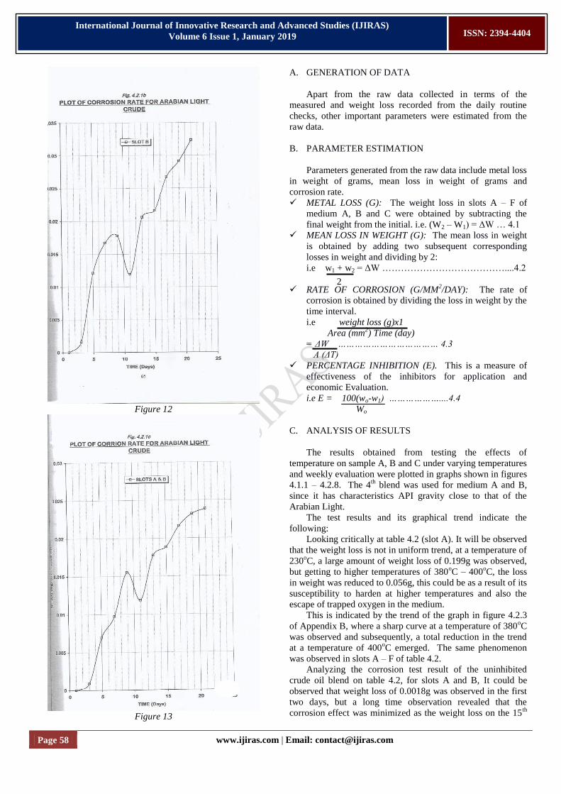
Looking critically at table 4.2 (slot A). It will be observed
that the weight loss is not in uniform trend, at a temperature of
230oC, a large amount of weight loss of 0.199g was observed,
but getting to higher temperatures of 380oC – 400
oC, the loss
in weight was reduced to 0.056g, this could be as a result of its
susceptibility to harden at higher temperatures and also the
escape of trapped oxygen in the medium.
This is indicated by the trend of the graph in figure 4.2.3
of Appendix B, where a sharp curve at a temperature of 380oC
was observed and subsequently, a total reduction in the trend
at a temperature of 400oC emerged. The same phenomenon
was observed in slots A – F of table 4.2.
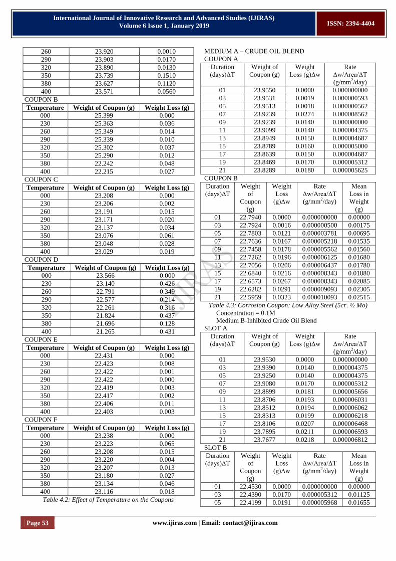
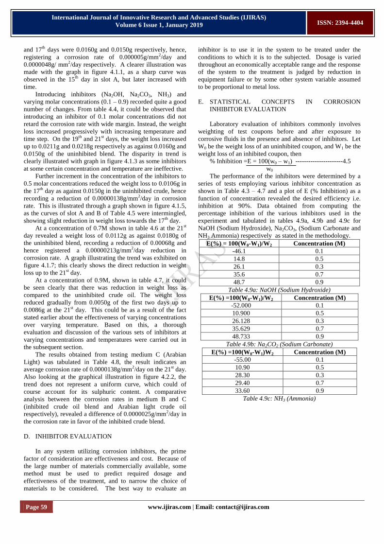
Analyzing the corrosion test result of the uninhibited
crude oil blend on table 4.2, for slots A and B, It could be
observed that weight loss of 0.0018g was observed in the first
two days, but a long time observation revealed that the
corrosion effect was minimized as the weight loss on the 15th
2
Page 59 www.ijiras.com | Email: [email protected]
International Journal of Innovative Research and Advanced Studies (IJIRAS)
Volume 6 Issue 1, January 2019
ISSN: 2394-4404
and 17th
days were 0.0160g and 0.0150g respectively, hence,
registering a corrosion rate of 0.000005g/mm2/day and
0.0000048g/ mm2/day respectively. A clearer illustration was
made with the graph in figure 4.1.1, as a sharp curve was
observed in the 15th
day in slot A, but later increased with
time.
Introducing inhibitors (Na2OH, Na2CO3, NH3) and
varying molar concentrations (0.1 – 0.9) recorded quite a good
number of changes. From table 4.4, it could be observed that
introducing an inhibitor of 0.1 molar concentrations did not
retard the corrosion rate with wide margin. Instead, the weight
loss increased progressively with increasing temperature and
time step. On the 19th
and 21st days, the weight loss increased
up to 0.0211g and 0.0218g respectively as against 0.0160g and
0.0150g of the uninhibited blend. The disparity in trend is
clearly illustrated with graph in figure 4.1.3 as some inhibitors
at some certain concentration and temperature are ineffective.
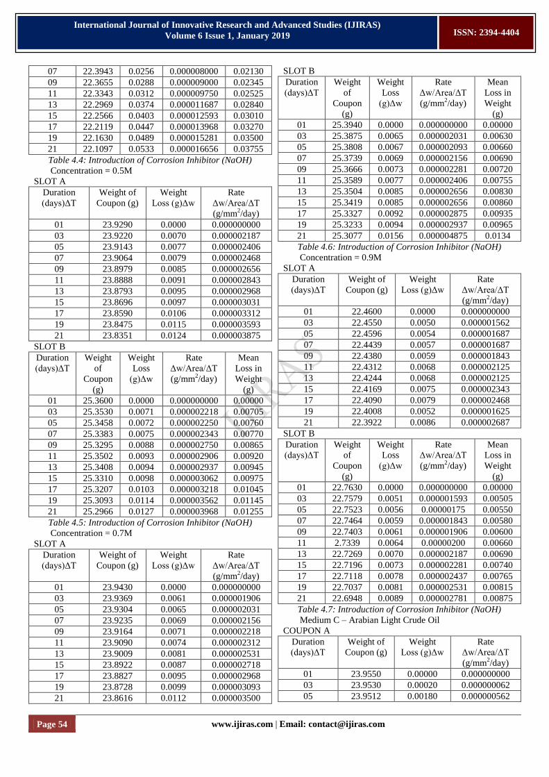
Further increment in the concentration of the inhibitors to
0.5 molar concentrations reduced the weight loss to 0.0106g in
the 17th
day as against 0.0150g in the uninhibited crude, hence
recording a reduction of 0.00000138g/mm2/day in corrosion
rate. This is illustrated through a graph shown in figure 4.1.5,
as the curves of slot A and B of Table 4.5 were intermingled,
showing slight reduction in weight loss towards the 17th
day.
At a concentration of 0.7M shown in table 4.6 at the 21st
day revealed a weight loss of 0.0112g as against 0.0180g of
the uninhibited blend, recording a reduction of 0.00068g and
hence registered a 0.00000213g/mm2/day reduction in
corrosion rate. A graph illustrating the trend was exhibited on
figure 4.1.7; this clearly shows the direct reduction in weight
loss up to the 21st day.
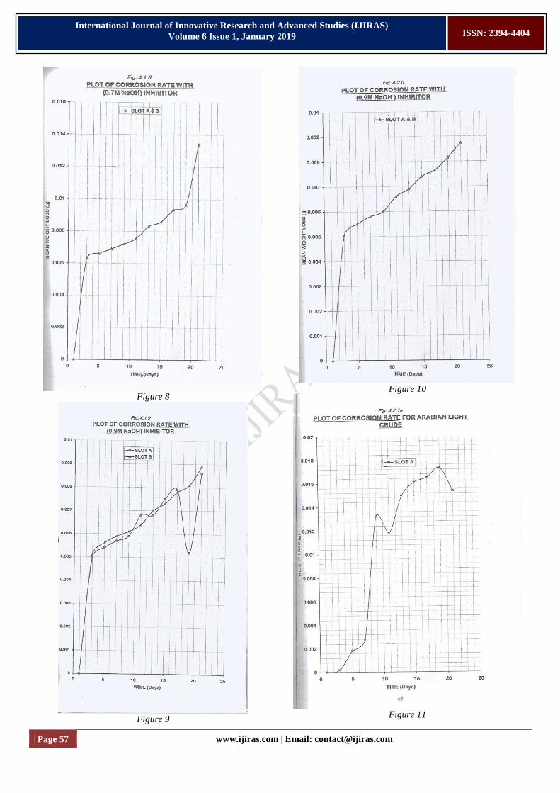
At a concentration of 0.9M, shown in table 4.7, it could
be seen clearly that there was reduction in weight loss as
compared to the uninhibited crude oil. The weight loss
reduced gradually from 0.0050g of the first two days up to
0.0086g at the 21st day. This could be as a result of the fact
stated earlier about the effectiveness of varying concentrations
over varying temperature. Based on this, a thorough
evaluation and discussion of the various sets of inhibitors at
varying concentrations and temperatures were carried out in
the subsequent section.
The results obtained from testing medium C (Arabian
Light) was tabulated in Table 4.8, the result indicates an
average corrosion rate of 0.0000138g/mm2/day on the 21
st day.
Also looking at the graphical illustration in figure 4.2.2, the
trend does not represent a uniform curve, which could of
course account for its sulphuric content. A comparative
analysis between the corrosion rates in medium B and C
(inhibited crude oil blend and Arabian light crude oil
respectively), revealed a difference of 0.0000025g/mm2/day in
the corrosion rate in favor of the inhibited crude blend.
D. INHIBITOR EVALUATION
In any system utilizing corrosion inhibitors, the prime
factor of consideration are effectiveness and cost. Because of
the large number of materials commercially available, some
method must be used to predict required dosage and
effectiveness of the treatment, and to narrow the choice of
materials to be considered. The best way to evaluate an
inhibitor is to use it in the system to be treated under the
conditions to which it is to the subjected. Dosage is varied
throughout an economically acceptable range and the response
of the system to the treatment is judged by reduction in
equipment failure or by some other system variable assumed
to be proportional to metal loss.
E. STATISTICAL CONCEPTS IN CORROSION
INHIBITOR EVALUATION
Laboratory evaluation of inhibitors commonly involves
weighting of test coupons before and after exposure to
corrosive fluids in the presence and absence of inhibitors. Let
W0 be the weight loss of an uninhibited coupon, and W1 be the
weight loss of an inhibited coupon, then
% Inhibition =E = 100(w0 – w1) ----------------------4.5
w0
The performance of the inhibitors were determined by a
series of tests employing various inhibitor concentration as
shown in Table 4.3 – 4.7 and a plot of E (% Inhibition) as a
function of concentration revealed the desired efficiency i.e.
inhibition at 90%. Data obtained from computing the
percentage inhibition of the various inhibitors used in the
experiment and tabulated in tables 4.9a, 4.9b and 4.9c for
NaOH (Sodium Hydroxide), Na2CO3, (Sodium Carbonate and
NH3 Ammonia) respectively as stated in the methodology.
E(%) = 100(W0-W1)/W2 Concentration (M)
-46.1 0.1
14.8 0.5
26.1 0.3
35.6 0.7
48.7 0.9
Table 4.9a: NaOH (Sodium Hydroxide)
E(%) =100(W0-W1)/W2 Concentration (M)
-52.000 0.1
10.900 0.5
26.128 0.3
35.629 0.7
48.733 0.9
Table 4.9b: Na2CO2 (Sodium Carbonate)
E(%) =100(W0-W1)W2 Concentration (M)
-55.00 0.1
10.90 0.5
28.30 0.3
29.40 0.7
33.60 0.9
Table 4.9c: NH3 (Ammonia)
Page 60 www.ijiras.com | Email: [email protected]
International Journal of Innovative Research and Advanced Studies (IJIRAS)
Volume 6 Issue 1, January 2019
ISSN: 2394-4404
Figure 14
F. DISCUSSION OF RESULTS
It has been commonly asserted that corrosion tests in
inhibited systems often give poorly reproducible weight loss
data. Despite the curve taken, it was found that the inhibitor
merit ranks, as judged by weight loss data, gave no agreement
at intermediate inhibitor concentrations of economic interest.
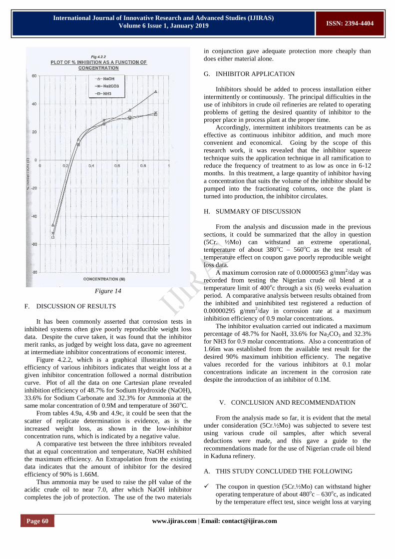
Figure 4.2.2, which is a graphical illustration of the
efficiency of various inhibitors indicates that weight loss at a
given inhibitor concentration followed a normal distribution
curve. Plot of all the data on one Cartesian plane revealed
inhibition efficiency of 48.7% for Sodium Hydroxide (NaOH),
33.6% for Sodium Carbonate and 32.3% for Ammonia at the
same molar concentration of 0.9M and temperature of 360oC.
From tables 4.9a, 4.9b and 4.9c, it could be seen that the
scatter of replicate determination is evidence, as is the
increased weight loss, as shown in the low-inhibitor
concentration runs, which is indicated by a negative value.
A comparative test between the three inhibitors revealed
that at equal concentration and temperature, NaOH exhibited
the maximum efficiency. An Extrapolation from the existing
data indicates that the amount of inhibitor for the desired
efficiency of 90% is 1.66M.
Thus ammonia may be used to raise the pH value of the
acidic crude oil to near 7.0, after which NaOH inhibitor
completes the job of protection. The use of the two materials
in conjunction gave adequate protection more cheaply than
does either material alone.
G. INHIBITOR APPLICATION
Inhibitors should be added to process installation either
intermittently or continuously. The principal difficulties in the
use of inhibitors in crude oil refineries are related to operating
problems of getting the desired quantity of inhibitor to the
proper place in process plant at the proper time.
Accordingly, intermittent inhibitors treatments can be as
effective as continuous inhibitor addition, and much more
convenient and economical. Going by the scope of this
research work, it was revealed that the inhibitor squeeze
technique suits the application technique in all ramification to
reduce the frequency of treatment to as low as once in 6-12
months. In this treatment, a large quantity of inhibitor having
a concentration that suits the volume of the inhibitor should be
pumped into the fractionating columns, once the plant is
turned into production, the inhibitor circulates.
H. SUMMARY OF DISCUSSION
From the analysis and discussion made in the previous
sections, it could be summarized that the alloy in question
(5Cr. ½Mo) can withstand an extreme operational,
temperature of about 380oC – 560
oC as the test result of
temperature effect on coupon gave poorly reproducible weight
loss data.
A maximum corrosion rate of 0.00000563 g/mm2/day was
recorded from testing the Nigerian crude oil blend at a
temperature limit of 400oc through a six (6) weeks evaluation
period. A comparative analysis between results obtained from
the inhibited and uninhibited test registered a reduction of
0.00000295 g/mm2/day in corrosion rate at a maximum
inhibition efficiency of 0.9 molar concentrations.
The inhibitor evaluation carried out indicated a maximum
percentage of 48.7% for NaoH, 33.6% for Na2CO3 and 32.3%
for NH3 for 0.9 molar concentrations. Also a concentration of
1.66m was established from the available test result for the
desired 90% maximum inhibition efficiency. The negative
values recorded for the various inhibitors at 0.1 molar
concentrations indicate an increment in the corrosion rate
despite the introduction of an inhibitor of 0.1M.
V. CONCLUSION AND RECOMMENDATION
From the analysis made so far, it is evident that the metal
under consideration (5Cr.½Mo) was subjected to severe test
using various crude oil samples, after which several
deductions were made, and this gave a guide to the
recommendations made for the use of Nigerian crude oil blend
in Kaduna refinery.
A. THIS STUDY CONCLUDED THE FOLLOWING
The coupon in question (5Cr.½Mo) can withstand higher
operating temperature of about 480oc – 630
oc, as indicated
by the temperature effect test, since weight loss at varying
Page 61 www.ijiras.com | Email: [email protected]
International Journal of Innovative Research and Advanced Studies (IJIRAS)
Volume 6 Issue 1, January 2019
ISSN: 2394-4404
operating temperatures recorded insignificant loss of
weight.
Blend work carried out in the research work justified the
reliability and efficiency of blending operation as an
alternative to Arabian light (crude) as it gave the same
characteristic property of the latter crude.
The corrosion rate of the crude blend was maximum at
0.00000563g/mm2/day for a maximum test temperature of
400oC at the peak of six (6) weeks.
Corrosion rate varied considerably with the medium in
context in other words, the corrosion rate measured by
medium B is always lower than that measured by medium
A, at the same temperature limit.
Corrosion tests in the inhibited systems gave poorly
reproducible weight-loss data. A maximum inhibition of
48.7% was recorded at a maximum concentration of 0.9
for NaOH, 36.6% for Na2C03 and 32.33% for Ammonia.
Hence, recommending NaOH, the most effective at an
operating temperature of 400oC. Thus a concentration of
1.66M is required for 90% effective inhibition.
A comparative analysis between the corrosion rate
measured by the crude oil blend and the Arabian light at
the same temperature limit indicates a reduction of
0.0000025 g/mm2/day in corrosion rate in favor of the
Nigerian crude oil blend and hence proves the
effectiveness of Sodium Hydroxide inhibitor and the
feasibility of the operational reliability and economic
evaluation.
A. RECOMMENDATIONS
From the analysis, discussions and conclusions made so
far, the following recommendations are necessary:
As has been previously mentioned, corrosion rate is
generally not uniform, so that safety factors must be
added to take account of accelerated corrosion in pitted
areas, because inhibitors generally are of decreasing
effectiveness at elevated temperatures above 300oF. The
top temperature for their use appears to be about 450oC,
which is far below the temperature of Kaduna refinery
streams, special alloys and coatings should be used in
such applications.
Since the sets of inhibitors evaluated are of neutralizing
type, they should be added continuously to every batch of
stream (crude oil) to be refined, by the “inhibitor squeeze”
technique at a molar concentration of 1.66M, since this
gives the maximum required percentage inhibition of
90%.
If in any case, the concentration of naphthenic acid in the
system should increase as to pose operational problem in
equipment malfunction, Ammonia should be used to raise
the pH of the acidic liquid to near 7.0, at the same
concentration of 1.66M.
In the absence of the above stated inhibitors, any other
inhibitors to be used should be tested and compared at
concentrations which would give inhibition efficiencies of
90-100%.
However, should a film forming inhibitor be used, then
the application have to be intermittently, to reduce the
frequency of treatment to as low as once in 6-12months.
In concordance with the inhibitor evaluation carried out in
this research work, it should be recommended strongly
that NaOH inhibitor be applied as the most economical
and effective inhibitor.
REFERENCES
[1] Philip V.P (1964): handbook of chemistry and physics
41st edition, chemical Rubber Publishing Co. P.P 16-20.
[2] Kick-ethmer (1984): An encyclopedia of chemical
technology vol. 7, 3rd edition.
[3] Speller, F.N.(1951): Corrosion: causes and prevention 3rd
Ed, Mc Graw-Hill inc. New York.
[4] Evans, U.R. (1961): The corrosion and oxidation of
metals, Arnold, 2nd edition P.P. 10-15.
[5] Clinton, P.P. (1961):Principles of metallic corrosion,
Royal institute of chemistry.
[6] Bradford, S.A. (1982): “Corrosion control published by
Reinhold” 2nd edition; P.P.1-8, 100-103.
[7] Evans, U.R. (1972):The Rusting of Iron; causes and
control Edward Arnold press, Ltd. London.
[8] Peabody, A.W. (1980): Corrosion Control on pipeline by
NACE, 1st edition, P.P.1- 20, 30.
[9] Pught, E.N. (1980): The Theory of stress corrosion
cracking in Alloys, Reynolds Publishers vol. 3, P.P 20-21.
[10] Khimiya, K.J. (1981): Corrosion and Protection of
Chemical Equipment by NACE Vol.5, P.P. 1-3.
[11] Grant,R.S. and Texter, H.E (1941): “Causes and
prevention of Drill pipe and Tool joint Failure” API
Drilling and Production Practice, P.P. 39-48.
[12] Rush, A.S, Barbee,R.D And Slimpson, J.P. (1966):
“Current Techniques for combating Drilling pipe
corrosion”, API Drilling and Production Practice, P.P. 59-
69.
[13] Thuren, J.B. and others: “Determining Temperature limits
of Drilling Effluents “Final Report Submitted to Sundia,
Contract No. E. (40-1)-5218, Jan. 1979.
[14] Maxwell, V.W: “Corrosion Inhibitor Evaluation at
Elevated Temperature”, Corrosion 16, 201t (1960).
[15] Barreth, J.P, and Claytor, E.E: “Flow Test for Evaluation
of Oil Fields Inhibitors”, Corrosion 18 (8), 277t (1962).
[16] 16. Purdy, G.E and Ries, W.L: “Corrosion of the results
obtained with Corrosion inhibitors in the Laboratory And
in the Field” Corrosion 12, 17t (1956).
[17] Lewis, C.F: “Statistics- A useful Tool for the Examination
of corrosion Data”, Corrosion 9, 38t (Jan.1953).
[18] Denman, W.L: “Electrical Resistance Corrosion
Measurements, Employing Alternating Current
“Corrosion 23, 43t (1957).