An Example in Steel Casting - Steel Founders' Society of ... · PDF fileAn Example in Steel...
26
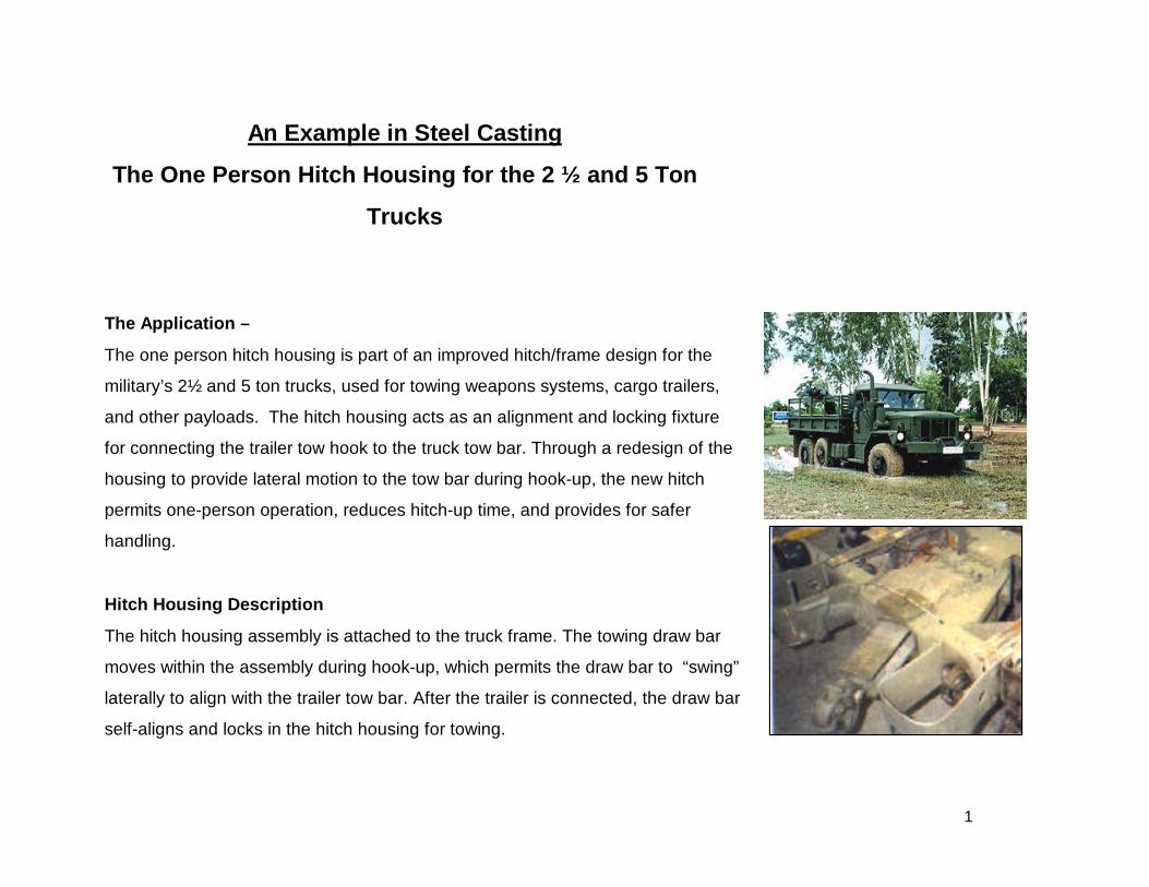
1 An Example in Steel Casting The One Person Hitch Housing for the 2 ½ and 5 Ton Trucks The Application – The one person hitch housing is part of an improved hitch/frame design for the military’s 2½ and 5 ton trucks, used for towing weapons systems, cargo trailers, and other payloads. The hitch housing acts as an alignment and locking fixture for connecting the trailer tow hook to the truck tow bar. Through a redesign of the housing to provide lateral motion to the tow bar during hook-up, the new hitch permits one-person operation, reduces hitch-up time, and provides for safer handling. Hitch Housing Description The hitch housing assembly is attached to the truck frame. The towing draw bar moves within the assembly during hook-up, which permits the draw bar to “swing” laterally to align with the trailer tow bar. After the trailer is connected, the draw bar self-aligns and locks in the hitch housing for towing.
-
Upload
trinhhuong -
Category
Documents
-
view
228 -
download
2
Transcript of An Example in Steel Casting - Steel Founders' Society of ... · PDF fileAn Example in Steel...
1
An Example in Steel Casting
The One Person Hitch Housing for the 2 ½ and 5 Ton
Trucks
The Application –
The one person hitch housing is part of an improved hitch/frame design for the
military’s 2½ and 5 ton trucks, used for towing weapons systems, cargo trailers,
and other payloads. The hitch housing acts as an alignment and locking fixture
for connecting the trailer tow hook to the truck tow bar. Through a redesign of the
housing to provide lateral motion to the tow bar during hook-up, the new hitch
permits one-person operation, reduces hitch-up time, and provides for safer
handling.
Hitch Housing Description
The hitch housing assembly is attached to the truck frame. The towing draw bar
moves within the assembly during hook-up, which permits the draw bar to “swing”
laterally to align with the trailer tow bar. After the trailer is connected, the draw bar
self-aligns and locks in the hitch housing for towing.
2
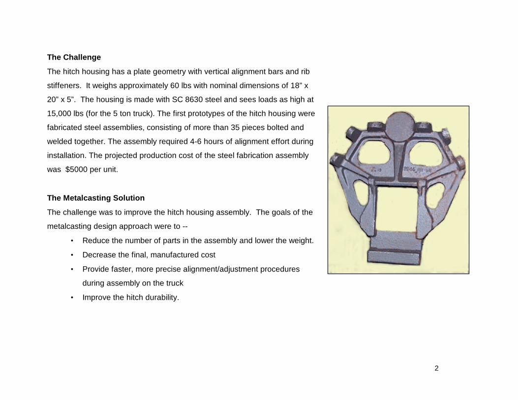
The Challenge
The hitch housing has a plate geometry with vertical alignment bars and rib
stiffeners. It weighs approximately 60 lbs with nominal dimensions of 18” x
20” x 5”. The housing is made with SC 8630 steel and sees loads as high at
15,000 lbs (for the 5 ton truck). The first prototypes of the hitch housing were
fabricated steel assemblies, consisting of more than 35 pieces bolted and
welded together. The assembly required 4-6 hours of alignment effort during
installation. The projected production cost of the steel fabrication assembly
was $5000 per unit.
The Metalcasting Solution
The challenge was to improve the hitch housing assembly. The goals of the
metalcasting design approach were to --
• Reduce the number of parts in the assembly and lower the weight.
• Decrease the final, manufactured cost
• Provide faster, more precise alignment/adjustment procedures
during assembly on the truck
• Improve the hitch durability.
3
What questions did the Casting Engineer ask in considering metalcasting for theOne Person Hitch Housing?• Is the component design optimized for casting manufacturability, as well as performance?
The casting (and its casting pattern) must be designed so that directional solidification and casting soundness
are promoted, tooling costs are minimized, and stress concentrators are reduced.
• How does the alloy requirement affect the casting design and fabrication of this component?
In casting steel alloys, the casting designer has to consider how the steel flows into the mold to provide rapid
fill without turbulent flow. The mold must have properly placed and sized risers to feed liquid metal into casting
during solidification.
A COST EFFECTIVEMETAL CASTING
The Right Alloy The Right Design
The Right Casting Process
4
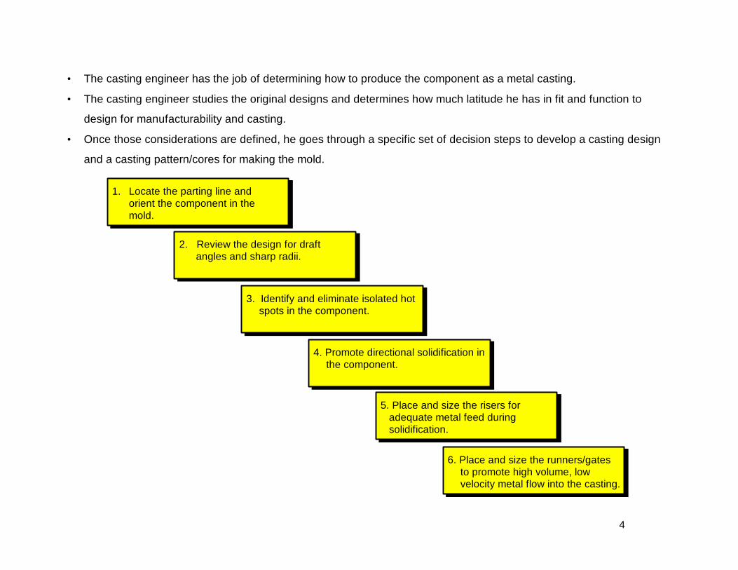
• The casting engineer has the job of determining how to produce the component as a metal casting.
• The casting engineer studies the original designs and determines how much latitude he has in fit and function to
design for manufacturability and casting.
• Once those considerations are defined, he goes through a specific set of decision steps to develop a casting design
and a casting pattern/cores for making the mold.
1. Locate the parting line andorient the component in themold.
2. Review the design for draftangles and sharp radii.
3. Identify and eliminate isolated hotspots in the component.
4. Promote directional solidification inthe component.
5. Place and size the risers foradequate metal feed duringsolidification.
6. Place and size the runners/gatesto promote high volume, lowvelocity metal flow into the casting.
5
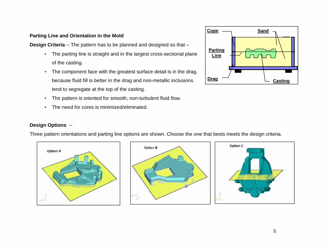
Parting Line and Orientation in the Mold
Design Criteria -- The pattern has to be planned and designed so that –
• The parting line is straight and in the largest cross-sectional plane
of the casting.
• The component face with the greatest surface detail is in the drag,
because fluid fill is better in the drag and non-metallic inclusions
tend to segregate at the top of the casting.
• The pattern is oriented for smooth, non-turbulent fluid flow.
• The need for cores is minimized/eliminated.
Design Options --
Three pattern orientations and parting line options are shown. Choose the one that bests meets the design criteria.
Drag
Cope
Casting
Sand
PartingLine
6
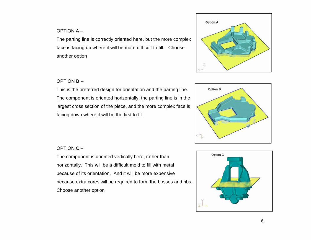
OPTION A –
The parting line is correctly oriented here, but the more complex
face is facing up where it will be more difficult to fill. Choose
another option
OPTION B --
This is the preferred design for orientation and the parting line.
The component is oriented horizontally, the parting line is in the
largest cross section of the piece, and the more complex face is
facing down where it will be the first to fill
OPTION C –
The component is oriented vertically here, rather than
horizontally. This will be a difficult mold to fill with metal
because of its orientation. And it will be more expensive
because extra cores will be required to form the bosses and ribs.
Choose another option
7
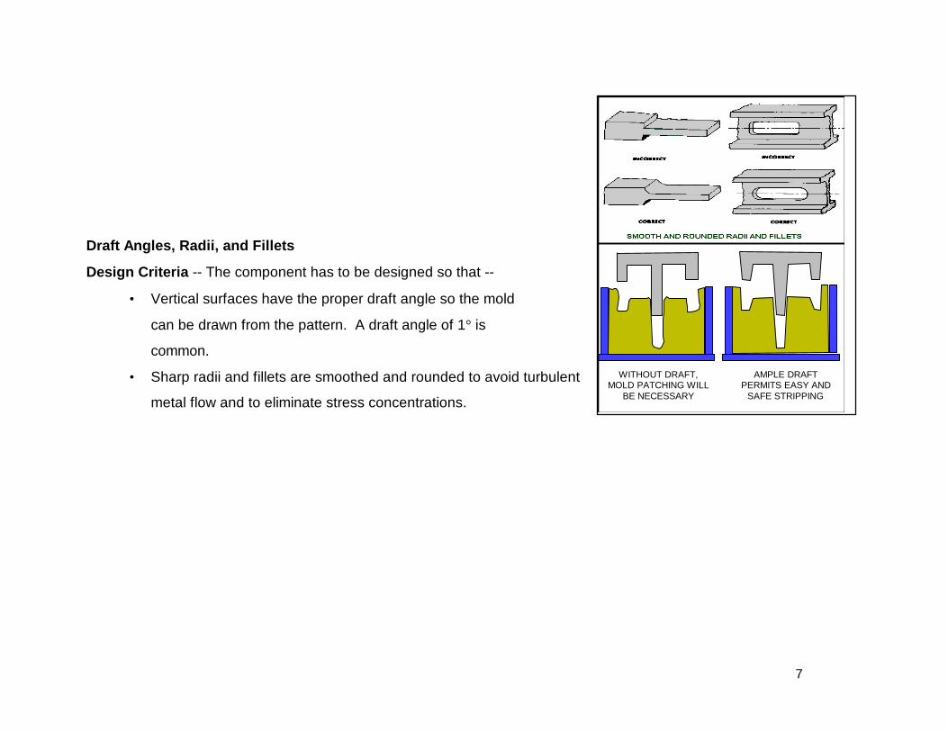
Draft Angles, Radii, and Fillets
Design Criteria -- The component has to be designed so that --
• Vertical surfaces have the proper draft angle so the mold
can be drawn from the pattern. A draft angle of 1° iscommon.
• Sharp radii and fillets are smoothed and rounded to avoid turbulent
metal flow and to eliminate stress concentrations.
WITHOUT DRAFT,MOLD PATCHING WILL
BE NECESSARY
AMPLE DRAFTPERMITS EASY AND
SAFE STRIPPING
8
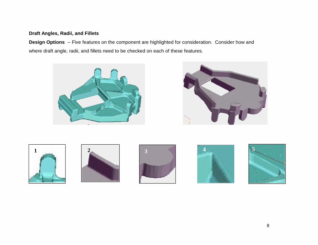
Draft Angles, Radii, and Fillets
Design Options -- Five features on the component are highlighted for consideration. Consider how and
where draft angle, radii, and fillets need to be checked on each of these features.
2 431 5
9
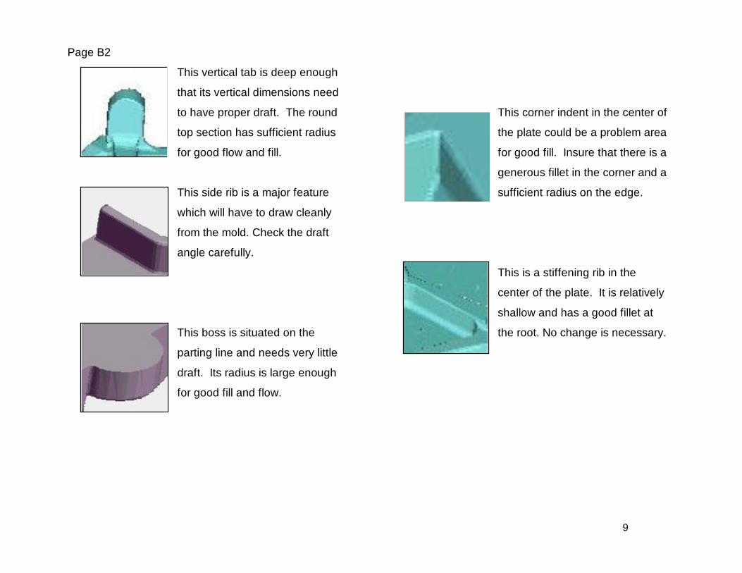
Page B2
This vertical tab is deep enough
that its vertical dimensions need
to have proper draft. The round
top section has sufficient radius
for good flow and fill.
This side rib is a major feature
which will have to draw cleanly
from the mold. Check the draft
angle carefully.
This boss is situated on the
parting line and needs very little
draft. Its radius is large enough
for good fill and flow.
This corner indent in the center of
the plate could be a problem area
for good fill. Insure that there is a
generous fillet in the corner and a
sufficient radius on the edge.
This is a stiffening rib in the
center of the plate. It is relatively
shallow and has a good fillet at
the root. No change is necessary.
10
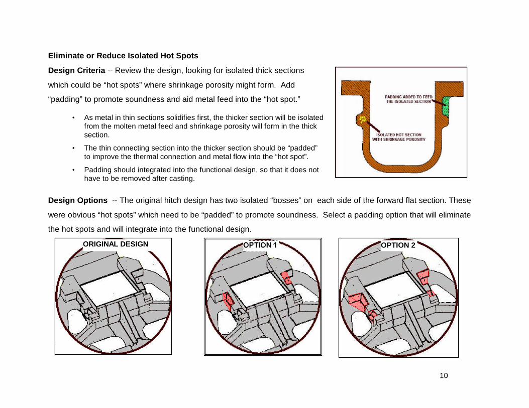
Eliminate or Reduce Isolated Hot Spots
Design Criteria -- Review the design, looking for isolated thick sections
which could be “hot spots” where shrinkage porosity might form. Add
“padding” to promote soundness and aid metal feed into the “hot spot.”
• As metal in thin sections solidifies first, the thicker section will be isolatedfrom the molten metal feed and shrinkage porosity will form in the thicksection.
• The thin connecting section into the thicker section should be “padded”to improve the thermal connection and metal flow into the “hot spot”.
• Padding should integrated into the functional design, so that it does nothave to be removed after casting.
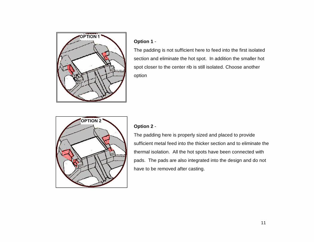
Design Options -- The original hitch design has two isolated “bosses” on each side of the forward flat section. These
were obvious “hot spots” which need to be “padded” to promote soundness. Select a padding option that will eliminate
the hot spots and will integrate into the functional design.
OPTION 2ORIGINAL DESIGN
11
Option 1 -
The padding is not sufficient here to feed into the first isolated
section and eliminate the hot spot. In addition the smaller hot
spot closer to the center rib is still isolated. Choose another
option
Option 2 -
The padding here is properly sized and placed to provide
sufficient metal feed into the thicker section and to eliminate the
thermal isolation. All the hot spots have been connected with
pads. The pads are also integrated into the design and do not
have to be removed after casting.
OPTION 2
12
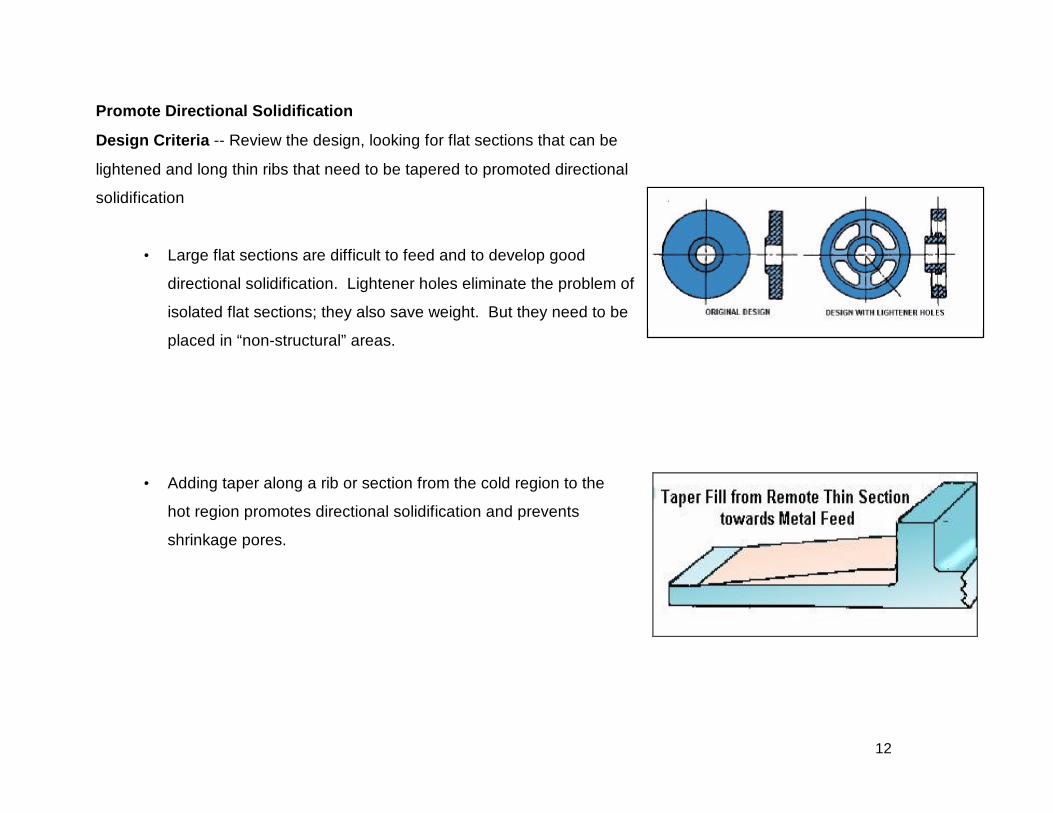
Promote Directional Solidification
Design Criteria -- Review the design, looking for flat sections that can be
lightened and long thin ribs that need to be tapered to promoted directional
solidification
• Large flat sections are difficult to feed and to develop good
directional solidification. Lightener holes eliminate the problem of
isolated flat sections; they also save weight. But they need to be
placed in “non-structural” areas.
• Adding taper along a rib or section from the cold region to the
hot region promotes directional solidification and prevents
shrinkage pores.
13
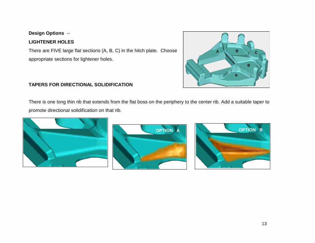
Design Options --
LIGHTENER HOLES
There are FIVE large flat sections (A, B, C) in the hitch plate. Choose
appropriate sections for lightener holes.
TAPERS FOR DIRECTIONAL SOLIDIFICATION
There is one long thin rib that extends from the flat boss on the periphery to the center rib. Add a suitable taper to
promote directional solidification on that rib.
OPTION A OPTION B
BA C
B
A
14
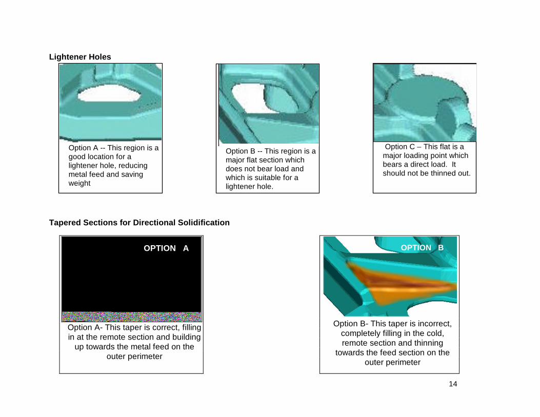
Lightener Holes
Tapered Sections for Directional Solidification
OPTION A
Option A- This taper is correct, fillingin at the remote section and building
up towards the metal feed on theouter perimeter
OPTION B
Option B- This taper is incorrect,completely filling in the cold,remote section and thinning
towards the feed section on theouter perimeter
Option A -- This region is agood location for alightener hole, reducingmetal feed and savingweight
Option B -- This region is amajor flat section whichdoes not bear load andwhich is suitable for alightener hole.
Option C – This flat is amajor loading point whichbears a direct load. Itshould not be thinned out.
15
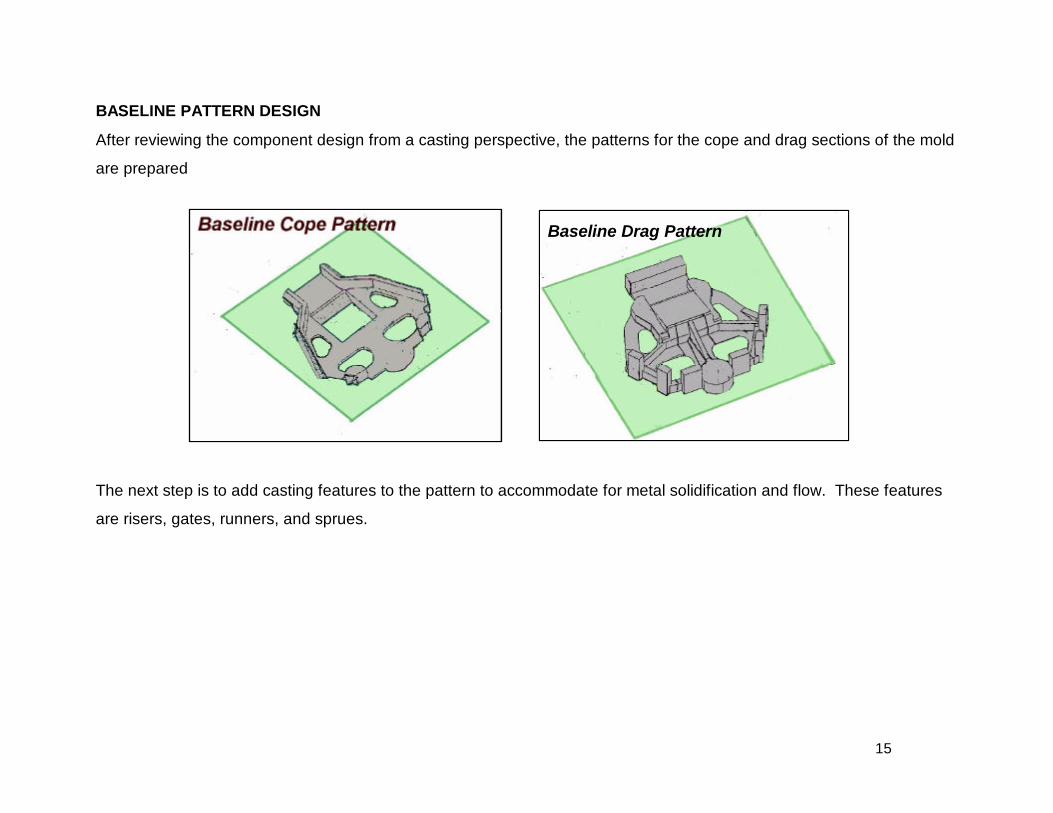
BASELINE PATTERN DESIGN
After reviewing the component design from a casting perspective, the patterns for the cope and drag sections of the mold
are prepared
The next step is to add casting features to the pattern to accommodate for metal solidification and flow. These features
are risers, gates, runners, and sprues.
Baseline Drag Pattern
16
Drag
Cope
Casting
Risers
Gate
Example of Risers and Gate
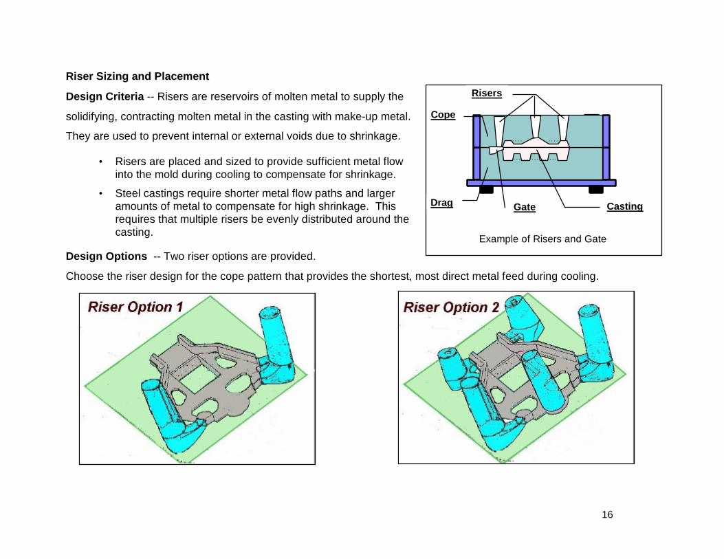
Riser Sizing and Placement
Design Criteria -- Risers are reservoirs of molten metal to supply the
solidifying, contracting molten metal in the casting with make-up metal.
They are used to prevent internal or external voids due to shrinkage.
• Risers are placed and sized to provide sufficient metal flowinto the mold during cooling to compensate for shrinkage.
• Steel castings require shorter metal flow paths and largeramounts of metal to compensate for high shrinkage. Thisrequires that multiple risers be evenly distributed around thecasting.
Design Options -- Two riser options are provided.
Choose the riser design for the cope pattern that provides the shortest, most direct metal feed during cooling.
17
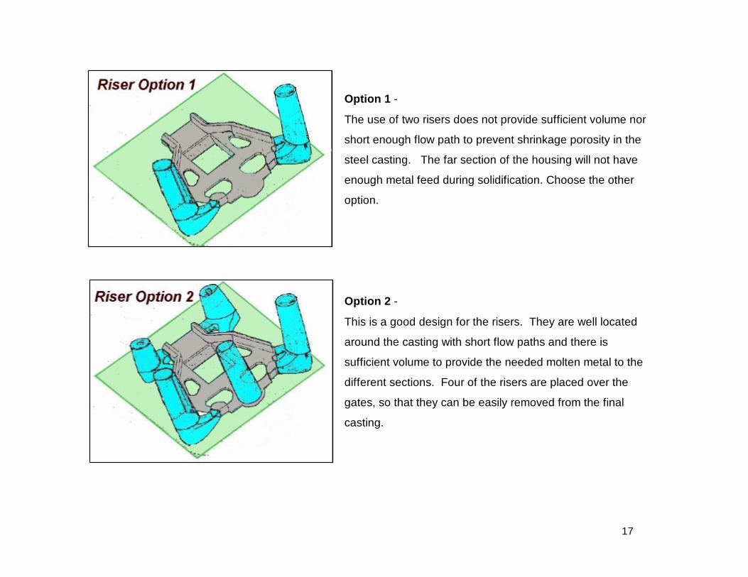
Option 1 -
The use of two risers does not provide sufficient volume nor
short enough flow path to prevent shrinkage porosity in the
steel casting. The far section of the housing will not have
enough metal feed during solidification. Choose the other
option.
Option 2 -
This is a good design for the risers. They are well located
around the casting with short flow paths and there is
sufficient volume to provide the needed molten metal to the
different sections. Four of the risers are placed over the
gates, so that they can be easily removed from the final
casting.
18
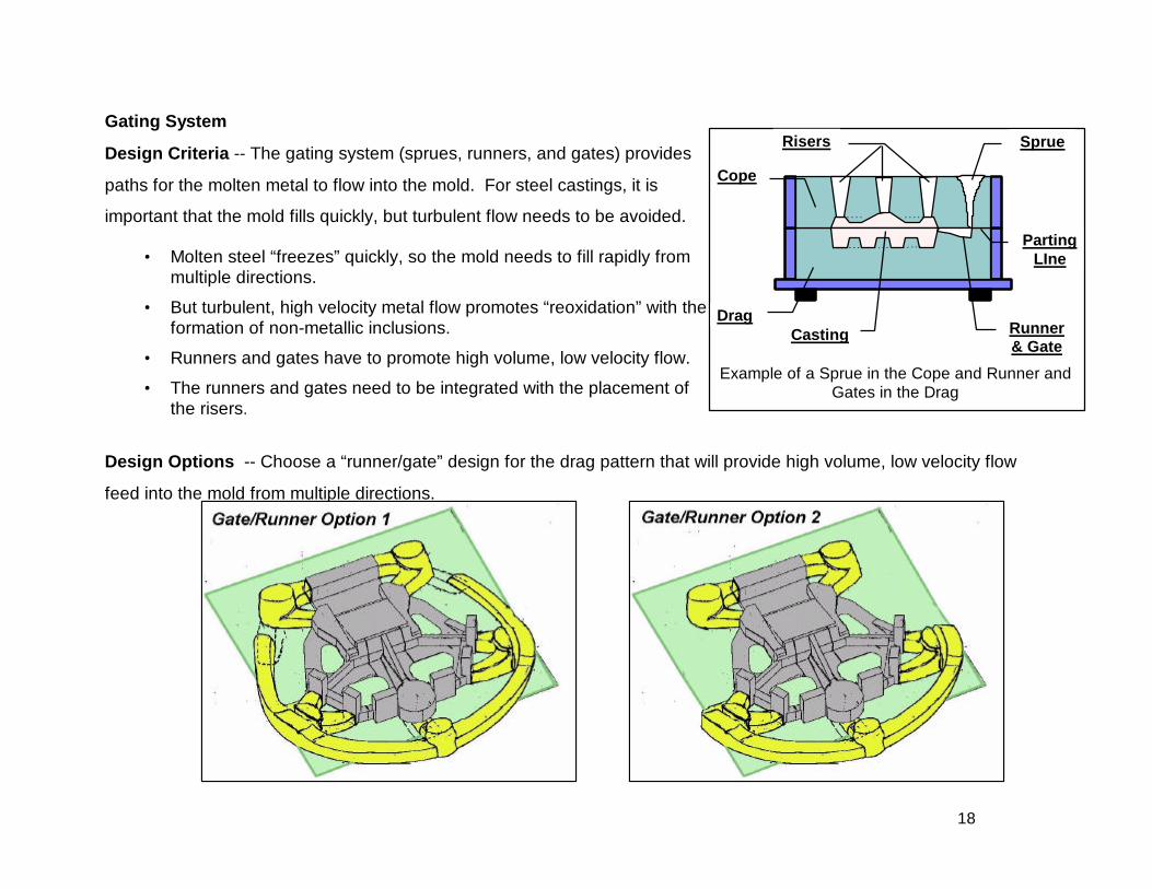
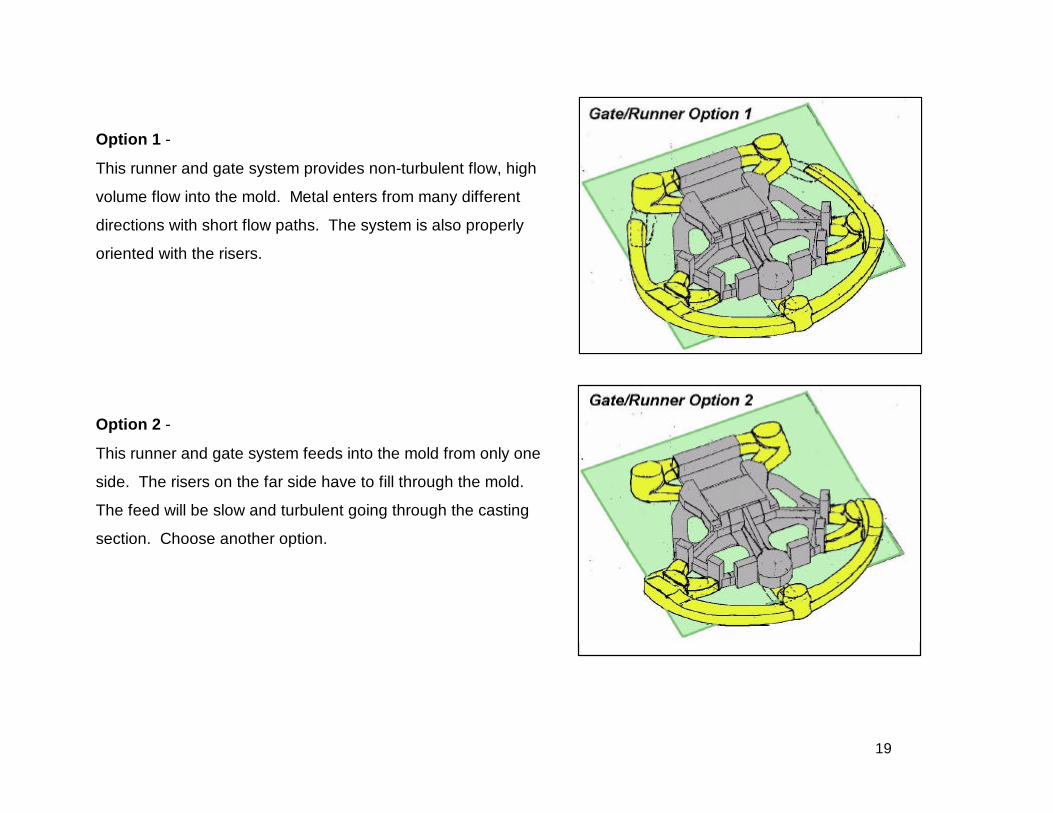
Gating System
Design Criteria -- The gating system (sprues, runners, and gates) provides
paths for the molten metal to flow into the mold. For steel castings, it is
important that the mold fills quickly, but turbulent flow needs to be avoided.
• Molten steel “freezes” quickly, so the mold needs to fill rapidly frommultiple directions.
• But turbulent, high velocity metal flow promotes “reoxidation” with theformation of non-metallic inclusions.
• Runners and gates have to promote high volume, low velocity flow.
• The runners and gates need to be integrated with the placement ofthe risers.
Design Options -- Choose a “runner/gate” design for the drag pattern that will provide high volume, low velocity flow
feed into the mold from multiple directions.
Drag
Cope
PartingLIne
Casting
SprueRisers
Runner& Gate
Example of a Sprue in the Cope and Runner andGates in the Drag
19
Option 1 -
This runner and gate system provides non-turbulent flow, high
volume flow into the mold. Metal enters from many different
directions with short flow paths. The system is also properly
oriented with the risers.
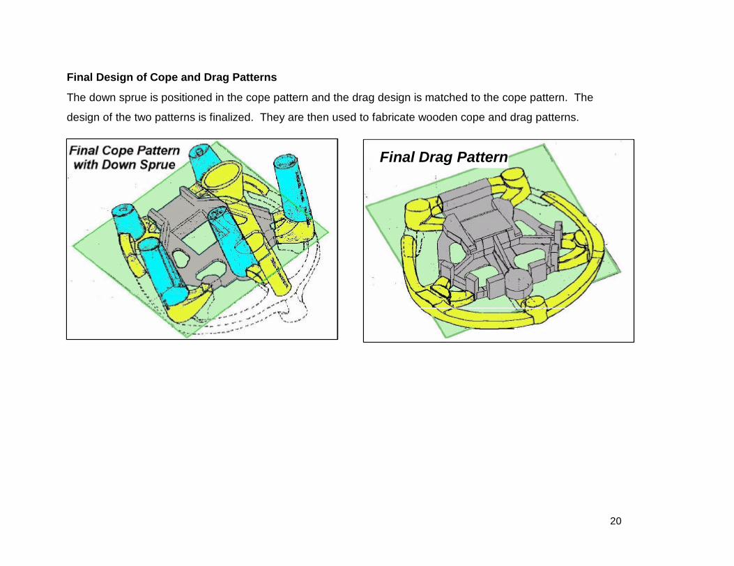
Option 2 -
This runner and gate system feeds into the mold from only one
side. The risers on the far side have to fill through the mold.
The feed will be slow and turbulent going through the casting
section. Choose another option.
20
Final Design of Cope and Drag Patterns
The down sprue is positioned in the cope pattern and the drag design is matched to the cope pattern. The
design of the two patterns is finalized. They are then used to fabricate wooden cope and drag patterns.
Final Drag Pattern
21
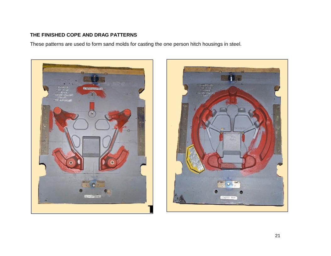
THE FINISHED COPE AND DRAG PATTERNS
These patterns are used to form sand molds for casting the one person hitch housings in steel.
22
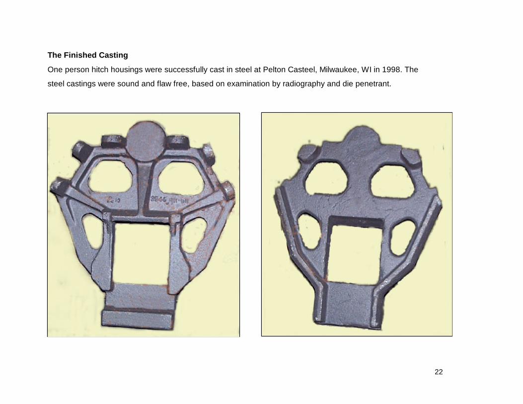
The Finished Casting
One person hitch housings were successfully cast in steel at Pelton Casteel, Milwaukee, WI in 1998. The
steel castings were sound and flaw free, based on examination by radiography and die penetrant.
23
SUMMARY
A steel casting was produced that met performance and cost goals. This was accomplished through a
sound understanding of casting principles and design, considering the factors of –
• Alloy Casting Properties
• Directional Solidification
• Metal Flow
• Mold and Pattern Design
By switching to a casting, cost and performance of the component were improved, compared to welded
assemblies.
• A simpler design with fewer parts (10) and lower weight.
• Lower manufactured cost.
• Faster, more precise alignment/adjustment procedures during installation.
• Improved durability over the steel assembly
24
Acknowledgement
The metalcasting examples are a joint effort of the Steel Founder’s Society of American and the
American Foundrymen’s Society.
Project funding was provided by the American Metal Casting Consortium Project, which is sponsored
by the Defense Logistics Agency, Attn: DLSC-T, Ft. Belvoir, VA 22060-6221.
Your comments and suggestions on these metalcasting examples are welcome.
Updated -- June 1998
25
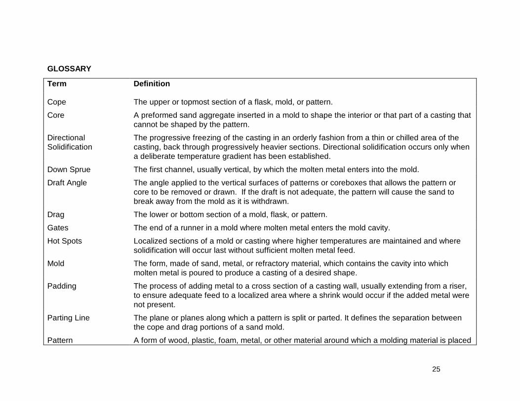
GLOSSARY
Term Definition
Cope The upper or topmost section of a flask, mold, or pattern.
Core A preformed sand aggregate inserted in a mold to shape the interior or that part of a casting thatcannot be shaped by the pattern.
DirectionalSolidification
The progressive freezing of the casting in an orderly fashion from a thin or chilled area of thecasting, back through progressively heavier sections. Directional solidification occurs only whena deliberate temperature gradient has been established.
Down Sprue The first channel, usually vertical, by which the molten metal enters into the mold.
Draft Angle The angle applied to the vertical surfaces of patterns or coreboxes that allows the pattern orcore to be removed or drawn. If the draft is not adequate, the pattern will cause the sand tobreak away from the mold as it is withdrawn.
Drag The lower or bottom section of a mold, flask, or pattern.
Gates The end of a runner in a mold where molten metal enters the mold cavity.
Hot Spots Localized sections of a mold or casting where higher temperatures are maintained and wheresolidification will occur last without sufficient molten metal feed.
Mold The form, made of sand, metal, or refractory material, which contains the cavity into whichmolten metal is poured to produce a casting of a desired shape.
Padding The process of adding metal to a cross section of a casting wall, usually extending from a riser,to ensure adequate feed to a localized area where a shrink would occur if the added metal werenot present.
Parting Line The plane or planes along which a pattern is split or parted. It defines the separation betweenthe cope and drag portions of a sand mold.
Pattern A form of wood, plastic, foam, metal, or other material around which a molding material is placed
26
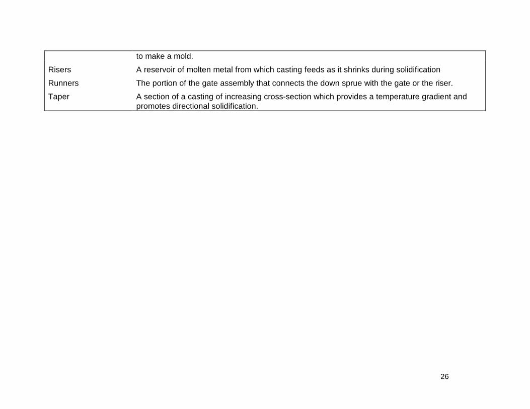
to make a mold.
Risers A reservoir of molten metal from which casting feeds as it shrinks during solidification
Runners The portion of the gate assembly that connects the down sprue with the gate or the riser.
Taper A section of a casting of increasing cross-section which provides a temperature gradient andpromotes directional solidification.