Examination of posterior capsular opacity under intraocular tamponade using silicone oil.

AN EXAMINATION OF THE EFFECT OF SILICONE TRANSFER ON PET FILM Kenneth. J. Muschelewicz, Ph.D. and Carl V. Pittillo, Mitsubishi Polyester Film, Inc. Brian Allen and Terry McEwen, Wacker Chemical Corp. ABSTRACT For over fifteen years, the use of polyester silicone coated release liner has grown significantly in the pressure sensitive tape market. With this growth, users of the substrate have become increasingly aware of potential performance issues that maybe associated with these liners. One issue, printability, is associated with silicone backside transfer. While this undesirable phenomenon is possible with any liner substrate, filmic liners are increasingly sensitive to this problem compared to paper based liners. Silicone transfer of free uncured silicone contamination to the backside surface of a release liner may result in printing performance issues such as print registration or ink adhesion. In this study, the joint efforts of Mitsubishi Polyester Film and Wacker Chemical attempted to understand the critical factors controlling silicone transfer, develop a quantifiable test procedure, and validate a diverse set of qualitative tests used by the industry. The results compared liner produced off-line to that produced in-line; they also identified some critical testing parameters and attempted to establish a relationship between measured backside transfer and silicone formulation variables. Lastly, in an attempt to correlate the results of the analytical testing to possible functional performance issues, an on-press printing trial was run directly on the non-silicone side of the various silicone coated polyester liners. The results demonstrated that good performance can be achieved via the off line process and very good material is produced via the in line process. INTRODUCTION and BACKGROUND The use of filmic materials in pressure sensitive applications continues to proceed at nearly double digit levels of annual growth. Significant inroads have been made in the specific use of polyester (PET) filmic base as the new release liner of choice. The huge growth has come as a result of the advantages that PET film offers as a release liner over paper base material. PET offers the user a release liner with the following key advantages:
• An ultra smooth surface, a perfect substrate for clear-on-clear “no-label look” applications
• A thinner substrate with more strength to resist tear out during high speed label dispensing
• Outstanding gauge (caliper) control • No remoisturization required for use

• A liner that is essentially debris free material, ideal for use in a clean room environment and in pharmaceutical packaging
These advantages have not only impacted the growth of PET film into the pressure sensitive tape and label market, but they have also expanded its use into medical applications, electronic applications, high tech. ceramics, carbon fibers and building products. To meet the growth in the market for filmic release liners, suppliers have invested and expanded their capacity. Additionally, the converters of base film into silicone coated release liner have enjoyed a steady business supporting growth of release liner sales. Off-line Coating (OLC) of Silicone Coated PET Film The traditional method used by converters to produce silicone treated release liners has been to take mill produced base film and treat the surface with a silicone resin. The silicone resin can be applied to the base film material using a variety of techniques. There are a multitude of roll coaters that have been constructed for applying silicone to the web. One very common traditional method is the application of a silicone resin using a set of rollers onto the substrate followed by the curing of the silicone using an energy source oven (Figure 1). The coating can be cured using thermal or ultraviolet energy, as the curing oven can be equipped with a heat source or bank of ultraviolet lamps. This technique, used by converters, may also be referred to as off-line coating (OLC).
Figure 1: Multi-roll silicone coating process
Plain uncoated substrate
Curing oven
Backing roller
5 stack off-set silicone coater
Silicone coated substrate

In-line Coating (ILC) of PET Film Another technique for production of silicone treated material, sometimes referred to as in-line coating (ILC), is when the substrate is manufactured in the mill having the treatment applied as part of the production of the mill roll. In the case of a typical PET film manufacturing process, the PET melt is cast onto a cooled drum forming a sheet that is then drawn in two steps (Werner, Janocha, Hopper, Mackenzie, 1988). The first draw is in the machine direction as the web traverses over a series of rollers. This is then followed by the second drawing where the film enters a tenter that contains clips that stretch the film in the transverse direction. This two step film forming process is referred to as biaxial orientation (Figure 2). After exiting the tenter, the film is wound on cores and slit to meet customer requirements.
Figure 2: Biaxial orientation film manufacturing process During this film forming process, chemical treatments may also be applied to give film products special surface features. Prior to exiting the tenter, the filmic material is heat-set to lock in specific mechanical characteristics, such as dimensional stability. The heat-setting takes place in a region of the tenter where the material experiences heating in excess of 230oC. These extremely high temperatures have a direct impact on the properties of the chemically treated surface. Specifically during the manufacturing of an in-line produced release liner, the silicone resin is applied to the PET prior to drawing into film. In this case, these high temperatures, along with the drawing action, have a direct effect on anchoring, cure, coat weight and ultimately the release behavior of the product produced in the mill. To support the growth in the use of release liners, the silicone suppliers, too, have expanded their product offerings to meet the ever growing demand of the market place. At the same time, due to environmental issues, silicone suppliers have, over the past several years, shifted their product offerings. These silicone suppliers have moved their customers away from solvent and tin catalyzed systems towards the supply and development of newer 100% solids thermal platinum and UV cured product offerings.
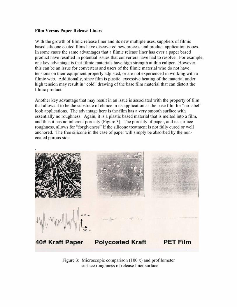
Film Versus Paper Release Liners With the growth of filmic release liner and its new multiple uses, suppliers of filmic based silicone coated films have discovered new process and product application issues. In some cases the same advantages that a filmic release liner has over a paper based product have resulted in potential issues that converters have had to resolve. For example, one key advantage is that filmic materials have high strength at thin caliper. However, this can be an issue for converters and users of the filmic material who do not have tensions on their equipment properly adjusted, or are not experienced in working with a filmic web. Additionally, since film is plastic, excessive heating of the material under high tension may result in “cold” drawing of the base film material that can distort the filmic product. Another key advantage that may result in an issue is associated with the property of film that allows it to be the substrate of choice in its application as the base film for “no label” look applications. The advantage here is the film has a very smooth surface with essentially no roughness. Again, it is a plastic based material that is melted into a film, and thus it has no inherent porosity (Figure 3). The porosity of paper, and its surface roughness, allows for “forgiveness” if the silicone treatment is not fully cured or well anchored. The free silicone in the case of paper will simply be absorbed by the non-coated porous side. .
Figure 3: Microscopic comparison (100 x) and profilometer surface roughness of release liner surface
0.25 μm
500 μm

However, in the case of filmic release liners, the smooth nonporous surface may potentially become a big issue. Here, any non reacted free silicone oil may contact the non-coated backside of the filmic material and transfer, contaminating the non-coated side of the liner. This may lead to issues with adhesive anchoring if the film is used as a backing for self wound tape. Or it can lead to issues with print registration, as the oil contamination will cause the back of the film to slip over backing rollers in print stations. Lastly, if the contaminated silicone oil backside is placed in contact with a highly activated print receptive label surface, which may occur when a laminated label is produced, then another transfer may take place. The contaminated back side now contaminates the print surface. This will result in printing “dewets” as the print surface now contains silicone contamination and when an attempt maybe made to print, especially with a water based ink, the ink will not wet out or adhere. Significant time and effort has been made by the producers of silicone coated PET films to minimize the potential silicone contamination due to existence of free silicone oil. Silicone Chemistry The first step needed to minimize the free amount of silicone oil is to maximize the cure of the reactive silicone system used in the coating process. Today, the majority of the release coatings used in the industry are 100% solids addition cure systems, therefore the discussion will concentrate on this chemistry. This chemistry consists of five basic components: 1. A silicone polymer with reactive vinyl groups either on the end of the polymer or in the pendant positions 2. Silicone-hydride functional crosslinkers (Si-H) 3. Platinum catalyst 4. Inhibitor- provides product bath life to allow for end-use processing 5. Controlled Release Additives- serve to increase release force
Figure 4: Addition cure mechanism

The first requirement for these systems to achieve full cure is to have a combination of time and temperature that will allow for the completion of the addition reaction. Temperature is needed for two reasons: (1) it is the mechanism to deactivate the cure inhibition effect, and (2) it greatly speeds up the reaction time. In full scale production applications for silicone release coatings, the combination of chemistry and engineering for the equipment installations dictates that full cure of the coating should be reached with 2-3 second residence times in the curing ovens at web temperatures from 150-190oC for paper substrates. For temperature sensitive substrates, such as olefin films, web temperatures of 100-120oC are more common, but residence times must be increased substantially or the chemistry modified to achieve full cure at these temperatures. Silicone cure is commonly measured by an extraction test performed on a finished coating. A sample of a coated substrate is immersed in a solvent for 24 hours, and the amount of silicone dissolved into the solvent is measured by Atomic Absorption (AA) or Inductively Coupled Plasma (ICP) Spectrometry. The amount of free silicon that is detected is calculated as a percentage of the total coating on the paper. Traditionally, as a general rule of thumb, 5% or less extractable silicone is considered a well cured coating. However, as more sophisticated surface treatments are employed on face stocks that may be contacted by a contaminated back side of a silicone liner new lower extractable targets are being requested. To reach the higher cure goals, the chemistry of the silicone system can be optimized to meet the performance requirements of the end use. Focusing only on the cure characteristics, the chemistry can be modified in the following ways: 1. Polymer chain length: Basic solvent free silicone release coating polymers have viscosities in the 200-500 mp-s range. For vinyl silicone polymers, the cure speed generally increases as the viscosity decreases. There are also several types of vinyl polymer structures available on the market today as well, and these can also influence the cure speed. Typical constructions include vinyl end blocked systems, end blocked and pendant vinyl polymers, and branched polymers. The reactivity and thus cure speed will increase as you move from pendant to end blocked to branched systems.
Figure 5: End blocked vinyl functional silicone polymer

Figure 6: End blocked and pendant vinyl functional silicone polymer
Cure Speed Comparison
0
5
10
15
20
25
30
6 3 2 1.5
Oven Residence Time
Silic
one
Extr
acta
bles
%
Branched polymer
200 mp-s polymer
300 mp-s polymer
500 mp-s end blocked polymer
Figure 7: Cure speed comparison for different silicone polymers
2. Inhibitor Content and Selection: There are a variety of inhibitors used to maintain bath life of the final catalyzed silicone system used in the coating process. The deactivation of the inhibitors is usually caused by heat, either the inhibitor is volatile and vaporizes as the temperature is increased, or higher temperature reduces the bond between the platinum catalyst and the inhibitor and then the catalyst can be activated. More volatile inhibitors usually provide faster curing systems, but at the expense of catalyzed bath life, especially in the thin film state seen in most coating processes.
S iO
S i
M e
M eO
S iO
S i
M e M e
M em n

3. Stoichiometry: Addition cure systems are typically formulated with a molar excess of crosslinker. This ratio of crosslinker to polymer in a system is generally expressed in the industry as the SiH/Vinyl ratio. Common ratios used to formulate can range from 1.2 to 2.5 or higher. An increase in SiH/Vinyl ratios will typically increase cure speed. An excess of hydrogen can lead to release stability problems with certain adhesives which are sensitive to residual SiH in the release coating. 4. Crosslinker Type: The structure of the crosslinker can also influence the cure rate. The composition of the crosslinker can be from 100% SiH, commonly called a homopolymer crosslinker, to varying combinations of SiH and SiMe in the crosslinker polymer chain, commonly termed copolymer crosslinkers. Copolymer crosslinkers provide faster cure rates than homopolymer crosslinkers. An increase in cure speed resulting from the introduction of a copolymer crosslinker unfortunately may also be met with a sacrifice in coating anchorage to the substrate. Silicone manufacturers have worked to overcome this problem by developing more exotic crosslinker compositions that maintain anchorage performance and cure speed performance at the same time.
Figure 8: Cure speed comparison for different types of crosslinkers
5. Platinum Level: Typically measured in ppm of platinum, the catalyst content is usually the easiest lever to drive cure rate, as it minimizes the side effects to other performance criteria compared to the other cure rate levers. However, with the recent increase in the cost of platinum metal on the market, reduction of platinum content has become the major topic in the release coating industry in the past 2-3 years. A 100 ppm catalyst level is usually regarded as the industry benchmark, with 50 ppm or less
Crosslinker Effect
0
5
10
15
20
25
30
35
6 3 2 1.5 1.2 Oven Residence Time (s)
% extracts
Homopolymer crosslinker
Copolymer crosslinker
Vinyl end blocked polymer with 100 ppm Platinum

considered to be low platinum. However, some applications on temperature sensitive substrates require levels of 150 to 200+ ppm to maintain adequate cure performance.
Figure 9: Cure speed dependence on platinum level
6. Release Additives: Additives used to increase the release force for silicone systems usually contain reactive silicone resins and polymers, plus in some cases reactive diluents. These products tend to slow down the cure rate as the percentage of the release additive in the formula is increased. 7. Content of unreactive silicone oils: In all silicone polymerization processes, a certain amount of non reactive low molecular weight polymers are produced as a byproduct. These oils can be removed by devolatalization in the production process, but a certain amount will always remain in the final product unless special measures are taken. These non reactive oils can greatly contribute to backside transfer since they will not be affected by any steps taken to increase the degree of cure. Thus, the formulation of silicone release coatings is a fairly complex process, and usually involves balancing a series of trade offs to meet the end use performance requirements. Nonetheless, there are sufficient tools in place in the industry today to meet these requirements at a reasonable cost.
Extracts vs. Pt level
0
1
2
3
4
5
6
7
8
100 80 70 60PPM Platinum
Extracts at 2 s oven time Vinyl end blocked polymer with 2 s oven residence time

ANALYSIS TECHNIQUES Silicone Extractables Silicone extraction testing is used to determine the degree of cure in a silicone release coating. Immediately after coating and curing of the silicone release onto the substrate, a known area of finished product is cut and immersed into a solvent. Typical solvent choices include toluene or xylene. The prepared sample is solvated over a period of twenty-four hours prior to analysis. Common analysis techniques are atomic absorption (AA) and inductively coupled plasma (ICP) spectrometry. The amount of uncured silicone is detected by either of these instruments on a volume basis. The amount of detected silicone by volume is correlated with the known sample size and silicone coating weight of the original sample to determine the percentage of uncured silicone. Industry preferences are less than 5% extractable silicone. Silicone extract values above 5% could lead to eventual product failure, through interaction of remaining SiH crosslinker with various adhesive systems. The type of adhesive chemistry also plays a role in this interaction, but the rule of thumb of less than 5% extracts should serve to reduce the potential for this interaction. Emphasis on immediate immersion of the silicone coated samples into the solvent of choice is a must. Thermally crosslinked platinum silicone systems will continue to crosslink after the inhibitor has been driven off. Failure to adhere to strict timing during sample preparation could lead to erroneous results. Surface Tension The cohesive forces between liquid molecules are responsible for the phenomenon known as surface tension. The molecules at the surface do not have other like molecules on all sides of them, and consequently they cohere more strongly to those directly associated with them on the surface. This forms a surface "film" which makes it more difficult to move an object through the surface than to move it when it is completely submersed. Surface tension is typically measured in dynes/cm, the force in dynes required to break a film of length 1 cm. Equivalently, it can be stated as surface energy in ergs per square centimeter. Water at 20°C has a surface tension of 72.8 dynes/cm compared to 22.3 for ethyl alcohol and 465 for mercury, whereas polyester film has a surface energy of 42 dynes/cm and the silicone surface has a surface energy of 22 dynes/cm. As previously stated, however, if there is free silicone that is uncured or contaminate in the silicone surface, then these free oils may undergo a transfer to a the backside surface of polyester film. Depending upon the level and amount of free silicone that may transfer, then the backside polyester surface dynes level may decrease by 10 – 20 dynes/cm.

XPS XPS (X-ray Photoelectron Spectroscopy), also commonly known as ESCA (Electron Spectroscopy for Chemical Analysis) provides quantitative information on all elements except hydrogen and helium, with a typical sampling depth of 50-100 Å (0.005-0.010 µm) at a normal (90°) photoelectron take-off angle (defined as the angle between the analyzer and the sample surface plane). In this ultra-high vacuum technique, the sample surface is irradiated with a monochromatic beam of soft x-rays, aluminum or magnesium Kα x-rays, to stimulate photoelectron emission. Photoelectron emission is analyzed to determine the elemental concentration and provide information on bonding chemistry by measuring binding energy shifts in the photoelectrons. Surface sensitivity may be enhanced by reducing the photoelectron take-off angle, commonly known as the grazing angle, or angular dependent, technique. For example, reduction of the take-off angle from 90° to 15° decreases the depth of analysis for the emitted photoelectrons, giving a sampling depth of 15-25Å.
Insulating samples, such as polymers, are rarely a problem for XPS. Surface charging is effectively controlled by a low energy charge neutralization electron gun used in combination with a low energy ion flood. XPS spectra are plotted as intensity in counts/second (Y axis) versus binding energy (X axis) in eV (electron volts) A relatively simple example of surface information obtained from XPS is:
• Separation of carbon chemistry functionality into: 1. Carbon-Carbon (hydrocarbon) bonding 2. Carbon single bonded to oxygen 3. Carbon double bonded to oxygen 4. Carbon-Carbon aromatic ring bonding
Figure 10: XPS scan for Carbon
1
3
4
2

EXPERIMENTAL Experimental Design The response-surface experimental design for this project encompassed one categorical and two numeric factors. Silicone polymer, the lone categorical factor, was varied across three types, linear vinyl end-capped, low-volatile content linear vinyl end-capped, and a branched species. Silicone crosslinker levels were examined from a hydride to vinyl ratio of 1.4 to 1.0 up to 2.4 to 1.0. The third and final factor was controlled release additive (CRA), which was varied from 0-40%. The intent of the off-line coating experimental design was to capture a wide-ranging cure profile, as measured by silicone extracts, as well as widely ranging finished product performance, as measured by end-use printability performance. The coating conditions for the two coating processes are presented in Tables 1 and 2. Silicone Off-line Coating Process The off-line coating process employed during silicone coating of the polyester film for this project was a five-roll transfer coating. A five-roll transfer coating utilizes variances in the gap between the first and second roll in combination with differential speeds between subsequent rollers to obtain the desired silicone coating weights (DeSanti, Ostness, 1992). The target silicone coating weight for this study was held constant at 1.0#/rm. The line speed employed was 500 fpm and the achieved exit web temperature hovered near 285°F. Estimated oven dwell time for the analysis was 1.8 seconds. Silicone In-line Coating Process The method to produce in-line silicone coated biaxially oriented PET film is as follows. First, the polyester melt is cast onto a chill drum. This cast sheet passes through and over a series of rollers where the sheet is oriented by stretching longitudinally (MD). Typically, for PET that is converted into silicone coated film it is stretched between 3 – 4 times. Next, the resulting forward drawn sheet is coated with a silicone chemical formulation. The film is now ready for its second draw. The coated sheet then moves into a tenter where the sheet is grabbed on both edges by clips that are mounted to a chain. The chains run parallel through the first section of the tenter oven where the sheet is preheated. In the next section of the tenter, the inter-chain distance is increased stretching the film transversely (TD). The sheet is drawn between 3 to 4 times in the transverse direction (TD). This biaxial orientation is what gives PET film its balance of properties for break strength, modulus and break elongation. Furthermore, the crystallinity is set by annealing or heat setting where the film is heated in excess of 230oC. It is at this point where the silicone coating will experience full cure.

Off-line coating conditionsOff-line Sam ple Num ber
SiH : S iVi % CRA CRA (#) Hydride (g) Run #Zone #2
Tem p (oF)Zone #3
Tem p (oF)Ct W t.
(#/ream )
1 2.4 0 EB 7.5 0 82 4/5 231 292 1.03
2 2.4 0 B 7.5 0 224 7/8 222 281 0.91
3 2.4 40 EBLV 4.5 3 225 10/11 226 283 1.09
4 1.4 0 EB 7.5 0 48 12/13 227 285 1.04
5 2.4 40 EB 4.5 3 225 15/16 227 283 0.98
6 2.15 10 EBLV 6.75 0.75 106 18/19 226 282 1.04
7 2.4 40 B 4.5 3 310 20/21 231 286 0.85
8 1.4 0 EBLV 7.5 0 48 22/23 233 282 1.12
9 1.4 40 EBLV 4.5 3 131 24/25 227 288 1.02
10 1.9 20 EB 6 1.5 122 27/28 199 250 1.05
11 1.9 0 EB 7.5 0 65 29/30 222 277 1.01
12 1.4 40 B 4.5 3 181 32/33 227 283 0.92
13 2.4 40 B 4.5 3 310 34/35 228 288 0.88
14 1.4 40 EBLV 4.5 3 131 36/37 229 282 1.02
15 1.4 40 B 4.5 3 181 38/39 229 285 0.92
16 1.4 0 B 7.5 0 130 40/41 227 282 1
17 1.4 40 EB 4.5 3 131 42/43 227 285 1.0518 2.4 0 B 7.5 0 224 44/45 230 286 0.96
NOTES: Runs #1, 2, & 3 used to establish roll ratios for coat weight EB Vinyl End BlockRun #6 used to check coat weight B Vinyl BranchedRun #9 used to check coat weight EBLV Vinyl End Block Low VolatilesRun #14 Low coat weight
Run #17 used to check coat weight
Run #26 High coat weight
Run #31 Low coat weight
Polym er (#)
Table 1: S ilicone Transfer Designed Experim ent
T a b le 2 : S i l i c o n e T r a n s f e r D e s ig n e d E x p e r im e n t
I n - l i n e c o a t in g c o n d i t i o n sI n - l i n e
S a m p le N u m b e r
S i H : S i V i H y d r i d e ( g )R u b - o f f
0 = n o n e / 6 = t o t a l f a i l u r e
1 1 E B 0 . 8 9 0 1 8 0
2 1 . 1 E B 0 . 8 8 3 1 8 0
3 1 . 3 E B 0 . 9 0 2 2 6 0
4 1 . 4 E B 0 . 8 3 2 2 6 0
5 1 . 4 E B L V 0 . 8 2 6 2 4 0
6 2 . 1 E B L V 0 . 8 2 6 3 8 0
7 2 . 5 E B L V 0 . 8 2 6 4 5 0
8 1 . 4 E B 0 . 8 2 6 2 4 0
9 2 . 1 E B 0 . 8 2 6 3 8 0
1 0 2 . 5 E B 0 . 8 2 6 4 5 0
1 1 1 . 4 B 0 . 8 2 6 5 1 0
1 2 2 . 1 B 0 . 8 2 6 7 5 01 3 2 . 5 B 0 . 8 2 6 9 4 0
* T h e c o a t w e i g h t o b t a i n e d i n l i n e i s r o u g h l y 1 0 0 t i m e s l o w e r t h a n t h e o f f l i n e c o a t w e i g h t s
P o l y m e r ( # )
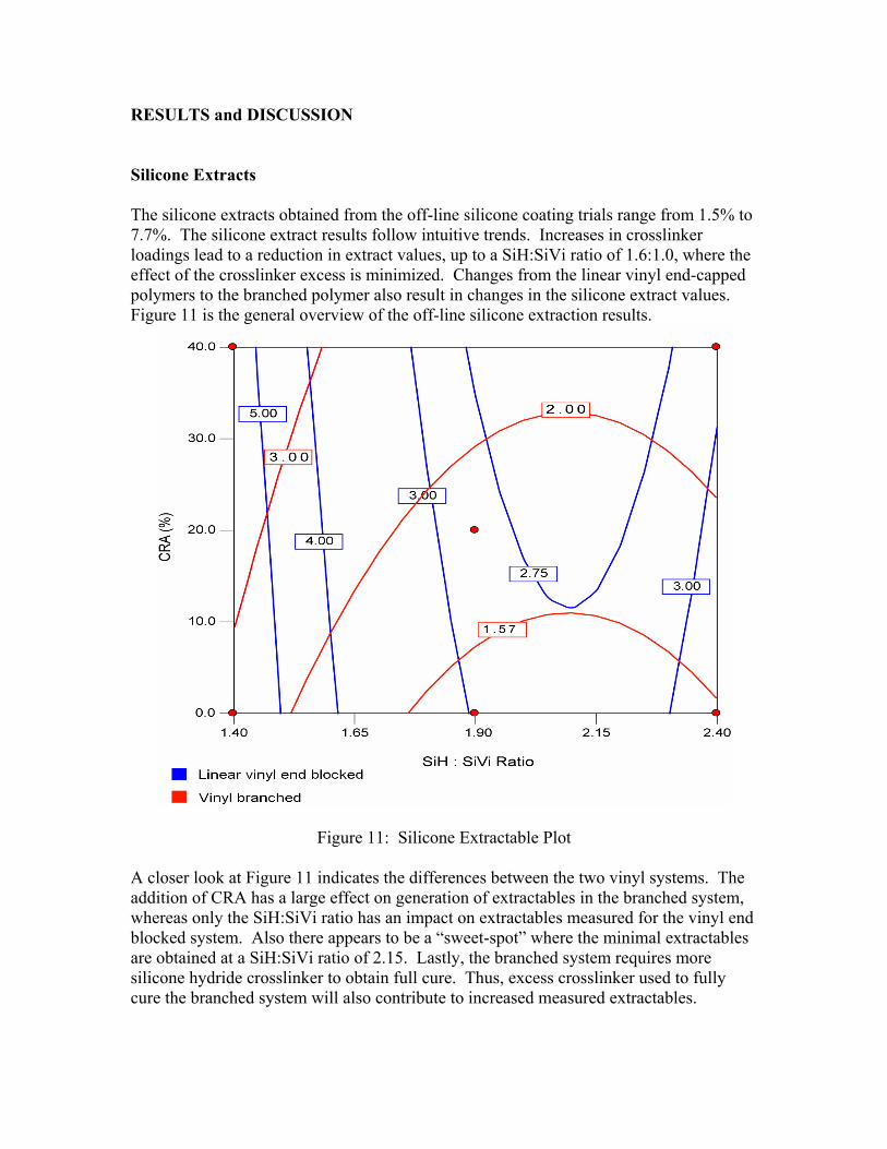
RESULTS and DISCUSSION Silicone Extracts The silicone extracts obtained from the off-line silicone coating trials range from 1.5% to 7.7%. The silicone extract results follow intuitive trends. Increases in crosslinker loadings lead to a reduction in extract values, up to a SiH:SiVi ratio of 1.6:1.0, where the effect of the crosslinker excess is minimized. Changes from the linear vinyl end-capped polymers to the branched polymer also result in changes in the silicone extract values. Figure 11 is the general overview of the off-line silicone extraction results.
Figure 11: Silicone Extractable Plot A closer look at Figure 11 indicates the differences between the two vinyl systems. The addition of CRA has a large effect on generation of extractables in the branched system, whereas only the SiH:SiVi ratio has an impact on extractables measured for the vinyl end blocked system. Also there appears to be a “sweet-spot” where the minimal extractables are obtained at a SiH:SiVi ratio of 2.15. Lastly, the branched system requires more silicone hydride crosslinker to obtain full cure. Thus, excess crosslinker used to fully cure the branched system will also contribute to increased measured extractables.

Increases in CRA content also served, as one might expect, to negatively impact the cure of the silicone coating. Please refer to Figure 12 for an analysis of the relationship between polymer type, CRA level, and resultant silicone extracts. The overlay plot provided outlines conditions during which less than 3% silicone extracts would be predicted.
Figure 12: Overlay extractable plot comparing hydride to vinyl ratio and CRA Silicone extractable testing performed on the in-line silicone coated product resulted in undetectable uncured silicone. In fact, via the ICP analytical method utilized for this testing, the results indicated negative values for some of the set points. Two theories exist to explain these results. The first is that the extremely low silicone coating weight (roughly 100 times lower for ILC versus OLC) employed, combined with limits on the analytical instrument’s ability to detect very small amounts captured for testing, results in an inability to accurately quantify the amount of uncured silicone obtained from the in-line process. The second theory is that the silicone coating is indeed essentially completely cured. While it may be difficult to believe that the silicone coating on the in-line product is completely cured, it is not unrealistic. Coating silicone in-line results in a very highly cured end product. This is due mainly to the processing conditions which include a relatively high heat profile in excess of 230oC.

Surface Tension Surface tension measurements were made on the non-silicone coated backside of the liner following intimate contact and aging of the wound rolls on samples collected from near the core. The back sides of the silicone coated films were evaluated using dynes solutions. Each solution has a standard dynes level. The dyne solution is carefully applied to the surface and the “wet out” versus “crawl back or beading up” of the solution is observed. The dynes level is the point where there is a difference between a solution that “wets out” and the next one that “beads up”. The results are summarized in Table 3. Table 3: XPS data, surface tension measurements, release and % extractables for off-line coated and in-line coated samples.
XPS Survey Data Surface Tension
Tesa 7475 Release Extracts
OLC Sample Number
Run Silicon 2p Carbon 1s Oxygen 1s dynes/cm gm/in (%Si via ICP)
1 4 4.4 66.8 28.9 35 10.9 2.92 8 4.1 67.3 28.7 35 17.4 1.53 11 6.5 64.2 29.4 35 17.1 2.94 13 5.3 65.8 29 34 8.2 7.35 16 5.4 65.3 29.4 35 15.5 3.36 19 4.2 67 28.9 35 9.4 2.57 21 4.7 65.9 29.4 35 22.8 2.78 23 4.5 66.6 28.9 35 7.0 7.79 25 5.9 64.6 29.5 35 11.2 5.210 28 3.7 67.2 29.1 36 7.4 3.211 30 3.7 67.4 28.9 35 8.7 2.812 33 4.6 65.4 30 35 17.2 4.113 35 4.6 66 29.5 35 25.9 2.314 37 5.5 64.9 29.6 35 14.7 5.115 39 4.6 65.5 29.9 35 18.1 4.416 41 4.7 65.7 29.7 36 10.6 2.517 43 5.3 65.1 29.7 35 12.8 4.418 45 4.7 66.7 28.7 35 15.2 1.5
Commercial OLC Control 11.7 59.6 28.6 <30 10.3 Not analyzed
ILC Sample Number
Equal to OLC
sampleSilicon 2p Carbon 1s Oxygen 1s dynes/cm gm/in Extracts
1 4.8 66.5 28.8 36 14.52 4.8 66.2 28.9 35 15.03 4.8 66.4 28.8 35 14.84 4.8 66.2 29.0 35 15.25 8 4.7 66.5 28.7 35 13.2 None6 4.9 66.4 28.7 35 13.5 detected 7 5.0 66.4 28.7 35 12.9 in8 4 5.0 66.2 28.7 35 13.4 any9 11 5.0 66.0 29.0 33 13.5 sample10 1 5.1 66.1 28.8 33 13.211 16 3.7 67.4 29.0 37 12.512 18 4.1 67.1 28.9 35 13.413 2 4.5 66.2 29.3 32 13.3

XPS The gathered XPS data does not appear to correlate well with measured silicone extracts. The initial hypothesis included an assumption that increases in silicone extracts would lead to increases in the amount of silicone transfer as measured by XPS on the backside of the liner. As Figure 13 demonstrates, there appears to be no straight line linear relationship between the data gathered via the two test methods.
Figure 13: Silicone Extracts vs. XPS measured % Atomic Silicon, OLC Process FUNCTIONAL ANALYSIS Release Performance Release was measured from Tesa® 7475 tape and is tabulated in Table 3. The test specimen was peeled at 12 in/min in an unsupported mode using an Instron. The peel strength for all the samples is summarized in Table 3. The release in general yielded an average release between 12.5 – 15 gm/in for the ILC samples and resulted in an average release between 7.4 – 25.9 gm/in for the OLC samples. Bear in mind that some of the OLC samples did contain a control release additive. Nonetheless, the release measurements are typical releases that one would expect to obtain from the types of silicone formulations run in the coating trials.

Print Trial An attempt was made to determine if there was a functional issue with the silicone contamination present on the backside of the liner. A major functional issue with silicone would be associated with a transfer from the contaminated back side to a laminated face stock that maybe wound into a roll. The contamination could possibly transfer again to the face stock, possibly affecting the printability of the face stock surface. Since it was not feasible to create a laminate label stock from the designed samples, it was decided to directly print the contaminated back side of the liner. The liner samples were printed at Global Packaging Solutions, Inc. using a series of water based inks on an 18 inch wide Comco Commander ten color flexographic printing press. The samples were then examined to determine if ink dewetting was occurring. The printed samples were then examined under magnification looking for areas where the ink would bead up due to contamination. Unfortunately, the differences in the surface tensions for the samples were not large enough to detect any significant dewetting issues. However, it was observed that in some samples where the surface tension was the lowest that there were some regions of slight irregularities observed in the inks on the ‘cooler’ operator side of the printing equipment versus the ‘hotter” drive side of the printer. The print operator commented that by adjusting the printing drying conditions and line speeds that marginal wet out of the inks could be made to dry faster than the “crawl back”. This could essentially cover-up a dewet/crawl back ink issues associated with surface contamination. The difference in the wetting out of the green ink can be observed in Figure 14 operator side versus Figure 15 the drive side.
Figure 14: Green ink dewets on operator side of printing press, ILC process
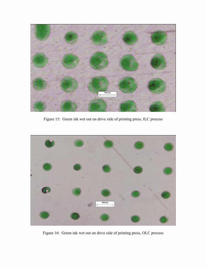
Figure 15: Green ink wet out on drive side of printing press, ILC process
Figure 16: Green ink wet out on drive side of printing press, OLC process
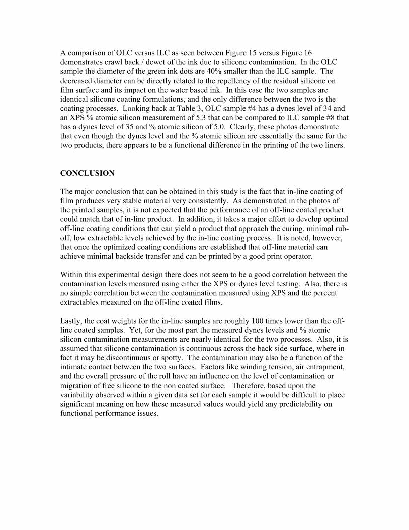
A comparison of OLC versus ILC as seen between Figure 15 versus Figure 16 demonstrates crawl back / dewet of the ink due to silicone contamination. In the OLC sample the diameter of the green ink dots are 40% smaller than the ILC sample. The decreased diameter can be directly related to the repellency of the residual silicone on film surface and its impact on the water based ink. In this case the two samples are identical silicone coating formulations, and the only difference between the two is the coating processes. Looking back at Table 3, OLC sample #4 has a dynes level of 34 and an XPS % atomic silicon measurement of 5.3 that can be compared to ILC sample #8 that has a dynes level of 35 and % atomic silicon of 5.0. Clearly, these photos demonstrate that even though the dynes level and the % atomic silicon are essentially the same for the two products, there appears to be a functional difference in the printing of the two liners. CONCLUSION The major conclusion that can be obtained in this study is the fact that in-line coating of film produces very stable material very consistently. As demonstrated in the photos of the printed samples, it is not expected that the performance of an off-line coated product could match that of in-line product. In addition, it takes a major effort to develop optimal off-line coating conditions that can yield a product that approach the curing, minimal rub-off, low extractable levels achieved by the in-line coating process. It is noted, however, that once the optimized coating conditions are established that off-line material can achieve minimal backside transfer and can be printed by a good print operator. Within this experimental design there does not seem to be a good correlation between the contamination levels measured using either the XPS or dynes level testing. Also, there is no simple correlation between the contamination measured using XPS and the percent extractables measured on the off-line coated films. Lastly, the coat weights for the in-line samples are roughly 100 times lower than the off-line coated samples. Yet, for the most part the measured dynes levels and % atomic silicon contamination measurements are nearly identical for the two processes. Also, it is assumed that silicone contamination is continuous across the back side surface, where in fact it may be discontinuous or spotty. The contamination may also be a function of the intimate contact between the two surfaces. Factors like winding tension, air entrapment, and the overall pressure of the roll have an influence on the level of contamination or migration of free silicone to the non coated surface. Therefore, based upon the variability observed within a given data set for each sample it would be difficult to place significant meaning on how these measured values would yield any predictability on functional performance issues.

NEXT STEPS The initial hypothesis for this study included the thought that a correlation between silicone extracts and XPS data would exist. While this study did not serve to prove a correlation between results obtained from these two test methods, it is possible that expansion of the study to include higher extract levels might show a correlation. The assumption also exists that extract levels above 10% would likely lead to silicone transfer to the backside of the liner and to corresponding significant print issues. REFERENCES Werner, Eberhard; Janocha, Siegfried; Hopper, Michael; Mackenzie, Kenneth. Polyester Films, Encyclopedia of Polymer Sci. and Engineering 2nd Ed. Vol. #12, 1988. DeSanti, Ernest; Ostness, Lee. A Pilot Study of 3-roll and 5-roll Coating. Black Clawson Company. March 1992. Practical Surface Analysis by Auger and X-ray Photoelectron Spectroscopy, Edited by D. Briggs and M. P. Seah, 1983, John Wiley & Sons. Personal Communication, John G. Newman, Evans Analytical Group, Chanhassen, MN. Personal Communication, Dr. James Tse, Principal Scientist Surface Analysis, Avery Dennison Research Center, Pasadena, CA. Personal Communication, Paul Griswold, Global Packaging Solutions, Inc. Oakboro, NC.