An Evaluation of Associative Interface for SolidWorks and …€¦ · · 2010-06-242010 SIMULIA...
19
2010 SIMULIA Customer Conference 1 An Evaluation of Associative Interface for SolidWorks and ABAQUS/CAE Hung-Peng Li and Goang-Ding Shyu Baker Hughes Inc. Abstract: In the modern design and manufacturing world, shorter development cycle times are being demanded. In addition, engineers are being asked to perform more analyses and studies to improve their products. To meet the challenge, engineers will seek more ways to increase robustness and productivity. With the continued integration of computational tools, such as the associative import between SolidWorks and Abaqus/CAE, it is possible to analyze and reiterate designs, materials, and structures in a more productive and efficient fashion. With the assistance of the associative interface capability, one can quickly update design changes into the ABAQUS finite element (FE) pre-processing tool with just one click. This associative importing feature allows tremendous time savings and avoids time-consuming repetitions and mistakes in creating new FE meshes and models for newly imported modified geometries and designs. This new capability allows Abaqus/CAE to update the imported geometries in real time and also to retain the majority of FE analysis model features, such as partitions and meshing seeds, contact interactions, applied loads, and boundary conditions. It also provides the advantage of creating multiple FE models with a reasonable effort for parametric or sensitivity studies to account for design and manufacturing variations, for example, the imperfections of eccentricity and ovality on the effect of collapse pressures. A wide variety of completion tools were evaluated. The interfaces and the process of the associative function between SolidWorks and Abaqus/CAE will be shown. The summary and conclusion including pros and cons will be discussed. Keywords: Abaqus/CAE, SolidWorks, FEA, Finite Element Analysis, Associativity, Design of Experiments, Import, Parametric Study, Mesh, Geometry, Associative Interface, Oil Completion Tools. 1. Introduction Finite element analysis (FEA) has been widely used in various industries, including the oil and gas industry, to evaluate their designs, manufacturing, material, and field issues, etc. Recently, more emphasis has been put on the use of commercially computational tools, such as Abaqus, to analyze the products before testing and manufacturing the actual ones. It certainly contributes to the reductions of tests and developing cycling times. Eventually, it does induce quicker turn-around times and save millions of dollars.
Transcript of An Evaluation of Associative Interface for SolidWorks and …€¦ · · 2010-06-242010 SIMULIA...

2010 SIMULIA Customer Conference 1
An Evaluation of Associative Interface for SolidWorks and ABAQUS/CAE
Hung-Peng Li and Goang-Ding Shyu Baker Hughes Inc.
Abstract: In the modern design and manufacturing world, shorter development cycle times are being demanded. In addition, engineers are being asked to perform more analyses and studies to improve their products. To meet the challenge, engineers will seek more ways to increase robustness and productivity. With the continued integration of computational tools, such as the associative import between SolidWorks and Abaqus/CAE, it is possible to analyze and reiterate designs, materials, and structures in a more productive and efficient fashion.
With the assistance of the associative interface capability, one can quickly update design changes into the ABAQUS finite element (FE) pre-processing tool with just one click. This associative importing feature allows tremendous time savings and avoids time-consuming repetitions and mistakes in creating new FE meshes and models for newly imported modified geometries and designs. This new capability allows Abaqus/CAE to update the imported geometries in real time and also to retain the majority of FE analysis model features, such as partitions and meshing seeds, contact interactions, applied loads, and boundary conditions. It also provides the advantage of creating multiple FE models with a reasonable effort for parametric or sensitivity studies to account for design and manufacturing variations, for example, the imperfections of eccentricity and ovality on the effect of collapse pressures.
A wide variety of completion tools were evaluated. The interfaces and the process of the associative function between SolidWorks and Abaqus/CAE will be shown. The summary and conclusion including pros and cons will be discussed.
Keywords: Abaqus/CAE, SolidWorks, FEA, Finite Element Analysis, Associativity, Design of Experiments, Import, Parametric Study, Mesh, Geometry, Associative Interface, Oil Completion Tools.
1. Introduction
Finite element analysis (FEA) has been widely used in various industries, including the oil and gas industry, to evaluate their designs, manufacturing, material, and field issues, etc. Recently, more emphasis has been put on the use of commercially computational tools, such as Abaqus, to analyze the products before testing and manufacturing the actual ones. It certainly contributes to the reductions of tests and developing cycling times. Eventually, it does induce quicker turn-around times and save millions of dollars.

2 2010 SIMULIA Customer Conference
With the current high-performance computational environment, advanced commercial software, including CAD and FEA tools, has been used robustly for the improvements of conceptual designs by including more details and non-linear physics factors. The software is also capable of running a number of analyses in a reasonable timeframe to achieve design of experiments and design optimization. The creation of FE models is often found to be most labor-intensive and time consuming process. For a newly imported geometry, it is usually required to clean or repair the geometry, partitioning and meshing parts and assembly, and followed by creating boundary conditions, loads, contact interactions, constraints, and analysis steps. When the geometry has been changed or modified, the updated model will need to be imported and the majority of the model creation process repeated to form another finite element model. The repeated procedures are tedious and prone to errors. With conventional non-associative translators (such as IGES, ACIS, STEP, and Parasolid formats), there is no easy method but to recreate a new model step by step. SolidWorks is a popular CAD package which is being widely used by many corporations. It is a feature-based CAD tool with the capabilities of geometry creation and modification, multiple imported and exported file formats for third party packages, and direct links with other software. With the function of direct connection with other analysis tool like Abaqus, the created or updated geometry can be imported precisely to the third-party tool without losing geometry features. It also provides the advantage of exporting and importing geometry in a real-time fashion. Abaqus/CAE versions 6.7-EF and later releases provide a new enhancement of direct associative interface between SolidWorks and Abaqus/CAE. The SolidWorks associative interface allows the end users to import the geometry of a SolidWorks model to Abaqus/CAE. With this new function, the users can work side by side with SoildWorks and Abaqus/CAE windows. It provides the advantages of progressive modifications of the models in SolidWorks without losing model and analysis features assigned to the FEA models. It also provides a great advantage of conceptual design study via Abaqus-based FEAs by generated multiply FE models in association with the changes of geometry and designs inside SolidWorks. The goal of this study is to perform pilot trials on a wide variety of Baker Hughes oil completion tools. The evaluation of the capabilities of SolidWorks and Abaqus/CAE associativity for two example models are concluded. The pro & cons and a few issues are illustrated and compared. The current study is only focused on the use of “automatic associative import,” which is used to transfer a model from SolidWorks to Abaqus/CAE in a single step.
2. Requirements and Import Procedures
The SolidWorks associative interface is supported for the platforms Windows/x86-32 and Windows/x86-64. In order to activate and use this function, a few items are required as follows:

2010 SIMULIA Customer Conference 3
1. SolidWorks associative interface for windows add-in file must be installed inside the SolidWorks. The files could be downloaded from the Simulia website.
2. SolidWorks 2008 SP1 or newer versions is required. 3. The CAD connection toolset inside Abaqus/CAE. This functionality can be activated
with a SolidWorks associative interface license. 4. The functionality is available for Abaqus v6.8 or later.
After the fulfillment of the above components, one can start to import parts and assembly of a model from SolidWorks to Abaqus/CAE windows as the following steps:
1. Start an Abaqus/CAE window and select the Assembly module. 2. From the menu bar, choose Tools->CAD Interface->SoildWorks (see Figure 1).
Figure 1. Abaqus/CAE SolidWorks connection port.
3. From the pop-up dialog box, select Auto-assign port and click Enable. Abaqus/CAE
immediately displays the port number shown in the message area. 4. Open SolidWorks and read in a part of assembly (a group of parts) to be imported. Inside
the SolidWorks window, one should be able to see Abaqus icon and Abaqus option in the dropdown menu bar.
5. Select Abaqus->Export to Abaqus/CAE from the menu. 6. From the pop-up dialog box, toggle on the option of Open in Abaqus/CAE. Change the
working directory to the location which you would like to save your files. Make sure to toggle on Autosave files before export (see Figure 2).

4 2010 SIMULIA Customer Conference
7. Click the green check mark in the SolidWorks property manager. The model will be exported to Abaqus/CAE and the model should appear in the current Abaqus/CAE viewport.
8. If you continue to make the changes for the model in SolidWorks, click on the Export to Abaqus/CAE icon shown in the top left corner of the SolidWorks window to update the model in Abaqus/CAE simultaneously. The associating features defined in the model tree of the current CAE viewport should be updated immediately upon the changing of the geometry.
Figure 2. Export to Abaqus/CAE option in SolidWorks.
3. Examples
Several completion tools are used to test the capabilities of the associative interface between SolidWorks and Abaqus/CAE. The modification of the design features and geometries were tested thoroughly for the imported models. The updated model and history data defined inside the model tree under various modules were examined carefully due to the change of the geometry and design features. Two examples including a single and multiple part/assembly were discussed and shown in the following chapters.
3.1 Example – Inflatable Element (single-part assembly) A simple model, Inflatable Element, contains only one part and is being used to test the associativity functionality. See Figure 3 for the original design with a drilled hole in SolidWorks. The transferred model in Abaqus/CAE window is shown in Figure 4 after the associative importing from the original geometry shown in Figure 3. When viewing both models in CAD and
2010 SIMULIA Customer Conference 5
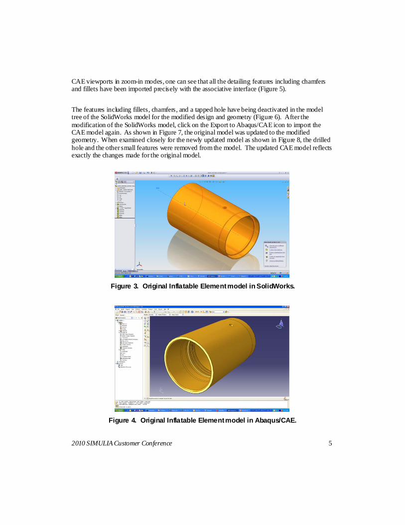
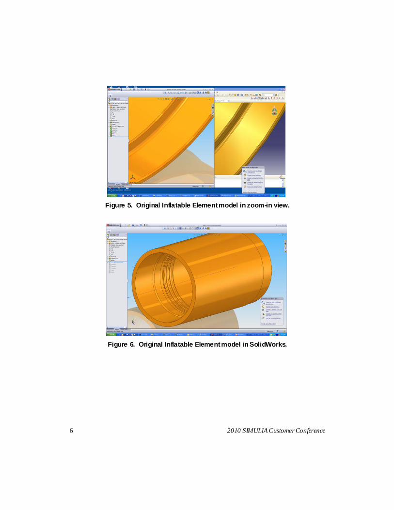
CAE viewports in zoom-in modes, one can see that all the detailing features including chamfers and fillets have been imported precisely with the associative interface (Figure 5). The features including fillets, chamfers, and a tapped hole have being deactivated in the model tree of the SolidWorks model for the modified design and geometry (Figure 6). After the modification of the SolidWorks model, click on the Export to Abaqus/CAE icon to import the CAE model again. As shown in Figure 7, the original model was updated to the modified geometry. When examined closely for the newly updated model as shown in Figure 8, the drilled hole and the other small features were removed from the model. The updated CAE model reflects exactly the changes made for the original model.
Figure 3. Original Inflatable Element model in SolidWorks.
Figure 4. Original Inflatable Element model in Abaqus/CAE.
6 2010 SIMULIA Customer Conference
Figure 5. Original Inflatable Element model in zoom-in view.
Figure 6. Original Inflatable Element model in SolidWorks.

2010 SIMULIA Customer Conference 7
Figure 7. Modified Inflatable Element model in Abaqus/CAE.
Figure 8. Modified Inflatable Element model in zoom-in view.
The geometry and parts/assembly features have been proven to be imported properly for the Inflatable Element model. The next step is to create features of the original CAE model inside the model tree. The tools have been analyzed by applying the burst and collapse pressures with fixed boundary conditions on both ends. A typical Abaqus-based FEA model has been built by creating model and history data for the current CAE model. Several features, such as sets, surfaces, meshing, element types, partitions, loads, and constraints, have been generated inside different modules, including part, property, assembly, mesh, and load. As the SolidWorks model illustrated

8 2010 SIMULIA Customer Conference
in Figure 3, the sequential steps to partition and mesh the imported CAE model (Figure 9) in the assembly level and mesh module have been listed from Figures 9 to 11.
Figure 9. Original Inflatable Element model in part module of Abaqus/CAE.
Figure 10. Partitioned original Inflatable Element model in mesh module of
Abaqus/CAE.
2010 SIMULIA Customer Conference 9
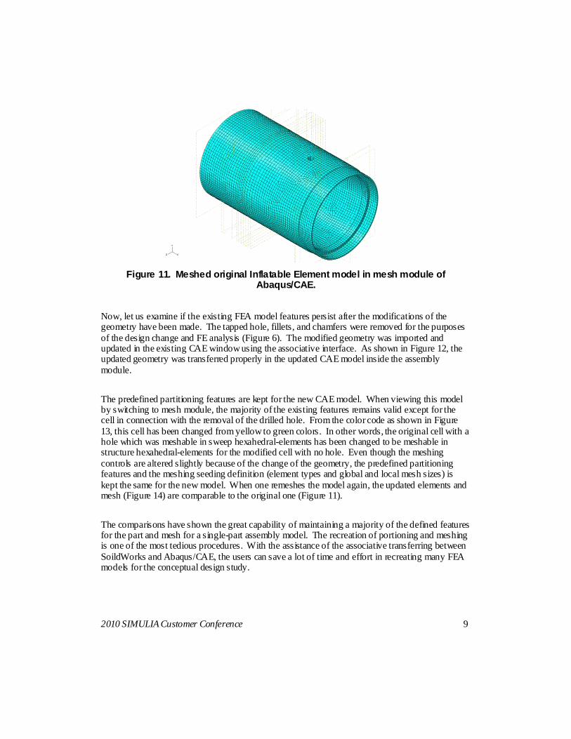
Figure 11. Meshed original Inflatable Element model in mesh module of
Abaqus/CAE.
Now, let us examine if the existing FEA model features persist after the modifications of the geometry have been made. The tapped hole, fillets, and chamfers were removed for the purposes of the design change and FE analysis (Figure 6). The modified geometry was imported and updated in the existing CAE window using the associative interface. As shown in Figure 12, the updated geometry was transferred properly in the updated CAE model inside the assembly module. The predefined partitioning features are kept for the new CAE model. When viewing this model by switching to mesh module, the majority of the existing features remains valid except for the cell in connection with the removal of the drilled hole. From the color code as shown in Figure 13, this cell has been changed from yellow to green colors. In other words, the original cell with a hole which was meshable in sweep hexahedral-elements has been changed to be meshable in structure hexahedral-elements for the modified cell with no hole. Even though the meshing controls are altered slightly because of the change of the geometry, the predefined partitioning features and the meshing seeding definition (element types and global and local mesh sizes) is kept the same for the new model. When one remeshes the model again, the updated elements and mesh (Figure 14) are comparable to the original one (Figure 11). The comparisons have shown the great capability of maintaining a majority of the defined features for the part and mesh for a single-part assembly model. The recreation of portioning and meshing is one of the most tedious procedures. With the assistance of the associative transferring between SoildWorks and Abaqus/CAE, the users can save a lot of time and effort in recreating many FEA models for the conceptual design study.

10 2010 SIMULIA Customer Conference
Figure 12. Modified Inflatable Element model in part module of Abaqus/CAE.
Figure 13. Partitioned modified Inflatable Element model in mesh module of
Abaqus/CAE.
Figure 14. Meshed modified Inflatable Element model in mesh module of
Abaqus/CAE.

2010 SIMULIA Customer Conference 11
The model features, such as sets or surfaces, could be defined in either part or assembly level since the whole assembly contains only one single part. The summary results of the comparisons of the prescribed features and the associated modules between original and updated Abaqus/CAE models are listed in the following Table 1.
Table 1. Checklist of the examined components for Inflatable Element CAE models under SoildWorks and Abaqus/CAE associativity import.
Module Defined features Results Import properly?
Part and Assembly Geometry Imported Yes
Part and Assembly Datum planes Imported Yes
Part and Assembly Partition Imported Yes
Part and Assembly Reference points Not imported No
Mesh Mesh seed and element types
Imported; need to remesh again
Yes, except for the cell with the removal
of the drilled hole
Part and Assembly Sets Imported Yes
Part and Assembly Surfaces Imported Yes
Load Pressure Imported Yes
Load Boundary conditions Imported Yes
Interaction Kinematic constraints Imported Yes, except for the control points which
are related to the reference points
Overall, the associativity function works very well for a single-part assembly model. The majority of the features are being transferred properly with progressive changes of geometry among the original and the updating models.

12 2010 SIMULIA Customer Conference
3.2 Example – Side Pocket Mandrel (multiple-parts assembly)
Another example study was to test a flow control device – Side Pocket Mandrel. The original model is the Side Pocket Mandrel with 1-in.-wide welding regions in between parts. The entire assembly contains 10 parts. The SolidWorks and the trasferred Abaqus/CAE models for original design are shown in Figure 15.
Figure 15. Original Side Pocket Mandrel model in both SolidWorks and Abaqus/CAE.
Under the associative interface, the imported results showed the geometry including all detailed features defined in part level were transferred precisely. However, the “Cut-Extrude1” feature prescribed in the assembly level was not honored in the associated CAE model (Figure 15). According to the Abaqus documentation, it has been considered as a limitation. This is one of the major limitations because it is easier for CAD users to create some features in assembly. For the current case, the author needs to regenerate cut-extrusion features in every part to complete the Abaqus/CAE model. Next, let us examine the assembly by hiding weld 1 – 4 parts for another design and analysis. As shown in Figure 16, the hidden parts, weld <1> to <4>, were modified for the SoldWorks model, whereas the imported Abaqus/CAE model reflects the exact change made for the modified model.

2010 SIMULIA Customer Conference 13
Figure 16. Original Side Pocket Mandrel model with 1-in. welding regions in both SolidWorks
and Abaqus/CAE.
Figure 17. Modified Side Pocket Mandrel model without 1-in. welding regions in both
SolidWorks and Abaqus/CAE.
The original Abaqus/CAE model was regenerated to analyze this tool under the combinations of tensile, compressive loads, and/or burst or collapse pressures. Several model and analysis features, including sets, surfaces, partitions, reference points, meshes, tied-constraints, and loads and boundary conditions, were created under different Abaqus/CAE modules.
14 2010 SIMULIA Customer Conference
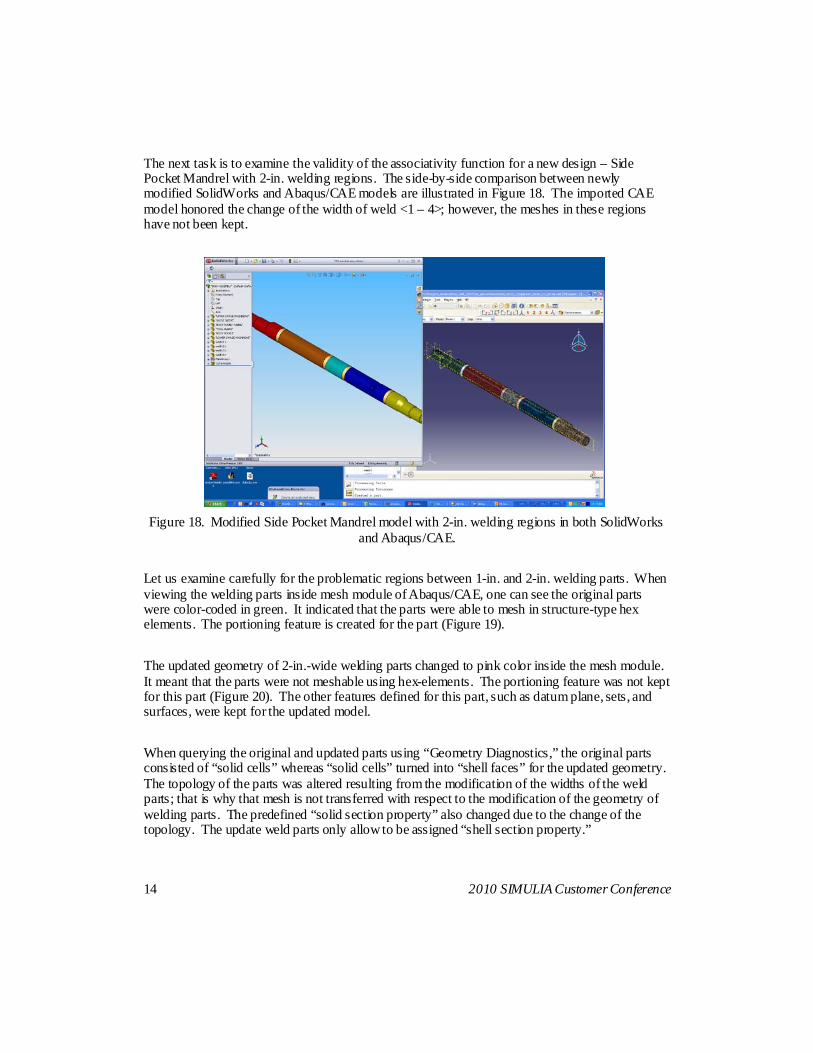
The next task is to examine the validity of the associativity function for a new design – Side Pocket Mandrel with 2-in. welding regions. The side-by-side comparison between newly modified SolidWorks and Abaqus/CAE models are illustrated in Figure 18. The imported CAE model honored the change of the width of weld <1 – 4>; however, the meshes in these regions have not been kept.
Figure 18. Modified Side Pocket Mandrel model with 2-in. welding regions in both SolidWorks
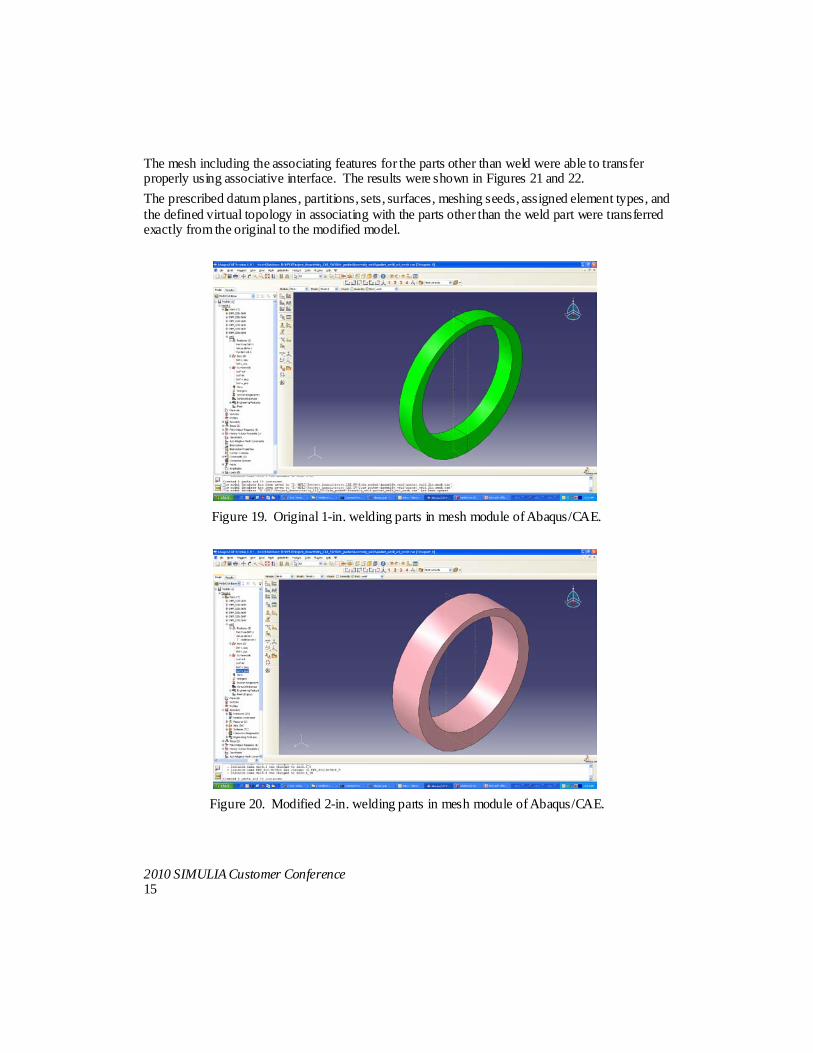
and Abaqus/CAE. Let us examine carefully for the problematic regions between 1-in. and 2-in. welding parts. When viewing the welding parts inside mesh module of Abaqus/CAE, one can see the original parts were color-coded in green. It indicated that the parts were able to mesh in structure-type hex elements. The portioning feature is created for the part (Figure 19). The updated geometry of 2-in.-wide welding parts changed to pink color inside the mesh module. It meant that the parts were not meshable using hex-elements. The portioning feature was not kept for this part (Figure 20). The other features defined for this part, such as datum plane, sets, and surfaces, were kept for the updated model. When querying the original and updated parts using “Geometry Diagnostics,” the original parts consisted of “solid cells” whereas “solid cells” turned into “shell faces” for the updated geometry. The topology of the parts was altered resulting from the modification of the widths of the weld parts; that is why that mesh is not transferred with respect to the modification of the geometry of welding parts. The predefined “solid section property” also changed due to the change of the topology. The update weld parts only allow to be assigned “shell section property.”
2010 SIMULIA Customer Conference 15
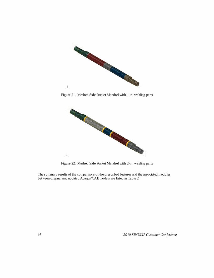
The mesh including the associating features for the parts other than weld were able to transfer properly using associative interface. The results were shown in Figures 21 and 22. The prescribed datum planes, partitions, sets, surfaces, meshing seeds, assigned element types, and the defined virtual topology in associating with the parts other than the weld part were transferred exactly from the original to the modified model.
Figure 19. Original 1-in. welding parts in mesh module of Abaqus/CAE.
Figure 20. Modified 2-in. welding parts in mesh module of Abaqus/CAE.
16 2010 SIMULIA Customer Conference
Figure 21. Meshed Side Pocket Mandrel with 1-in. welding parts
Figure 22. Meshed Side Pocket Mandrel with 2-in. welding parts
The summary results of the comparisons of the prescribed features and the associated modules between original and updated Abaqus/CAE models are listed in Table 2.

2010 SIMULIA Customer Conference 17
Table 2. Checklist of the examined components for Side Pocket Mandrel CAE models between original 1-in. and updated 2-in. weld parts under SoildWorks and
Abaqus/CAE associativity import.
Module Defined features Results Import properly?
Part and Assembly Geometry with modified welding
widths
Imported Yes
Assembly Cut-extrusion Not imported No
Part Datum planes Imported Yes
Part Partitions Imported except weld parts
Yes, except weld parts
Part Auto and combined faces virtual topology
Imported Yes
Part and Assembly Reference points Not imported No
Property Materials and section assignments
Imported except weld parts
Yes, except weld parts
Mesh Mesh seed and element types
Imported except weld parts
Yes, except weld parts
Part Sets Imported Yes
Part Surfaces Imported Yes
Load Pressure Imported Yes
Load Boundary conditions Imported Yes
Interaction Tied-constraints Imported Yes
Overall, the associativity function works very well for the assembly models except for the welding regions in which the geometry modifications were made. A majority of the features have been transferred properly with progressive changes of geometry among the original and the updated models.

18 2010 SIMULIA Customer Conference
4. Conclusion, Followup and Recommendations
The associativity between SolidWorks and Abaqus/CAE works very well. The updated geometries are able to import precisely from the examples tested for the current study. The majority of predefined features have been kept for the new models. Some features may fail to import or import incorrectly with the modification of the geometry. Overall, the pros, cons, and possible issues are summarized as follows:
1. Pros: • The function is user-friendly. • The associative interface provides real time in transferring models. • The tool offers more efficient studies for design of experiments to include design
progressive changes and variations in manufacturing. 2. Cons:
• The created and updated assembly features inside SolidWorks cannot be imported into the models in Abaqus/CAE. It is documented as a limitation.
• There is no bi-directional importing capability. • SolidWorks and Abaqus/CAE interface require additional license and cost.
3. Possible issues: • Some deficiency or problematic area from the results of case studies may be related
to either software bugs or limitations. • There are potential tokens and cost increases to perform design of experiment studies
using associative interface. Of course, there are many areas for improvement, but, the users can take advantage of this functionality to be much more productive by efficiently creating or modifying FEA models during design iterations. The SolidWorks associative interface provides additional advantages:
• To modify and repair the geometry inside SolidWorks after the FEA model is created • To reiterate the FEA model making and analyses for conceptual designs and
manufacturing tolerances and variations in more productive and efficient fashion • An excellent tool for design of experiments study
The possible bugs, limitations, and issues related to the tested models have being reported to Abaqus South supporting office and head office.

2010 SIMULIA Customer Conference 19
The followup study is to test more finite element models on different part and assembly features inside Abaqus/CAE. It is also to test associative importing capabilities due to different types of geometric changes, such as angles of the slips, collet fingers, and thread designs. The internal report and presentation have been made to colleagues during technology sharing meetings and conferences. The benefits of using this tool have been recommended to the company’s CAE and FEA users.
5. References
1. Abaqus Released Documentation, “SolidWorks Associative Interface User’s Guide,” Version 1, last updated in September, 2009.
2. Montgomery, Jerome, “An Evaluation of the Pro/ENGINEER Associative Interface for Abaqus/CAE,” 2008 Abaqus Users’ Conference, May 18 - 22, 2008.
3. Abaqus Answer ID 3430, “How to obtain the CATIA V5, SolidWorks and Pro/ENGINEER Associative Interface installation files, user guide, and status reports,” last updated in January, 2010.