“An energy revolution where your comfort costs less” - Air Supply Air
41
“An energy revolution where your comfort costs less” Relax In comfort with SolAir World’s Tri-System suppling Cooling in Summer, Heating in Winter and Hot Water all year long... SWT1-200 SWT1-270 SWT3-200 SWT3-270 INSTALLATION AND OPERATION INSTRUCTION MANUAL FOR THERMAL BOOSTED HOT WATER SYSTEMS:
Transcript of “An energy revolution where your comfort costs less” - Air Supply Air

“An energy revolution where your comfort costs less”
Relax In comfort with SolAir World’s Tri-System suppling Cooling in Summer, Heating in Winter and Hot Water all year long...
, g y g
SWT1-200 SWT1-270 SWT3-200 SWT3-270
INSTALLATION AND OPERATION INSTRUCTION MANUALFOR THERMAL BOOSTED HOT WATER SYSTEMS:

Operating Instructions and Installation GuideTri - System
_______________________Page 1
Note to users:____________________
Congratulations on purchasing a SolAir World Tri System. With your purchase you will enjoythe benefits of power savings and affordable comfort for many years to come.
To understand hou your SolAir World Tri System works and to ensure the best performance fromyour system please read the following information before installing or using your system.
1. This manual pertains only to the installation and operation of the SolAir World Tri water tank.This manual is primarily a reference document for the installation officer who has to be alicensed plumber.
2. The installation must comply with the requirements of AS/NZS 3500.4, AS/NZS 3000, and allall local codes and authority requirements.
3. Installation must be completed or checked off by a licensed plumber.Water tank is suggested to be installed at the place where it is close to the water pipe andpower supply.
4 NOTE: The water tank must be fitted with a RPTR. valve. The RPTR. valve should be checked For adequate performance and replaced at intervals not exceeding 2 years or more frequently in Areas where there are a high incidence of water deposits. The performance of valve must be Checked by gently opening valve easing gear at least one every 6 months. The discharge pipe For the RPTR. valve must reach less than 150mm to the floor drain.
5. The buyer should ensure that the anode must be replaced once every two years if the tank is installed in the area with bad water quality.

Operating Instructions and Installation GuideTri -System
_______________________Page 2
Contents
Note to users..................................................................................................................................
1. General Information
1.2 ........................................................................................................1.3 System ...........................................................................................1.4 System ........................................................................................................
2. Installation Guide
2.1 Installation ......................................................................................2.2 ................ ....................................................................2.3 Installation ........................................................................................2.4 Installation................................................................ ..2.5 Installation..........................................................................2.6 .............................................................2.7 ............................................................................................
3. Operating Instructions
3.1 .......................................................................................3.2 .................................................................................................
Page 4
Page 1
PagePage
Page Page
Page Page Page Page Page Page Page 1
Page 1
1.1 System Specifications......................................................................................................
2.8 ............................................................................Page 2. ............................................................................Page 2. ............................................................................Page

Operating Instructions and Installation GuideTri - System
_______________________Page
Section 1General Information

1.1 System specifications
Specifications and principal dimensions for the various systems and components are showntable 1.1.
Table 1.1 System Specifications
System TypeSWT-1 270SWT-3 270
Tank delivery capacity 270L 200 L
Solar flow and return 3/4” 3/4”
PTR Valve 3/4” 3/4”Cold Inlet 3/4” 3/4”Hot outlet 3/4” 3/4”PTR Valve setting (kPa) 850 850Rating of PTR Valve supplied (kW) 10 10
Power consumption of electric heating device(kW)
3.6 3.6
Number of collector 1 1
Collector inlet 3/4” 3/4”
Collector outlet 3/4” 3/4”
Circulation pump setting 1 1
Operating Instructions and Installation GuideTri - System
SolA i r Wor lds hot water system is commonly referred to as a Tri - system, it i s made up of six components. These six components are collector, storage tank, pump, controller, boost element and air conditioner unit.. A Tri - System is a system where the heated water in the solar collector is moved around by using a small circulation pump and pump controller. The pump draws water from the cold water connection to the tank and circulates the water through the collector, then returns the water back to the storage tank which has been heated free from the sun. When the air conditioner is fitted the refrigerant from the air conditioner passes through a coil inside the tank acting like a heater element in a kettle. When the air conditioner is operating it will heat the water for free.
Rated frequency
Rated Voltage
Dimension Dia.xHeight mm
Air Cond. Inlet/Outlet Diam
_______________________Page 4
240V
50Hz 50Hz
240V
648 x 1397 540 x 1502
9.4(³/8) 9.4 (³/8)
_________________
SWT-1 200SWT-3 200

Operating Instructions and Installation GuideTri - System
_______________________Page
1.2 Pump Specifications
GRUNDFOS SMALL UP COMPOSITE PROGRAMME
__________________

Operating Instructions and Installation GuideTri - System
_______________________Page
1.2 Pump SpecificationsSMALL UP COMPOSITE PROGRAMME
Housing name: CIL-2
The CIL2 housing (Composite In- Line Version 2) is available in 2 different composite material, made by injection moulding, using collapsible core technology: 1. Zytel 70G30 HSR2 BK-309 is a ultra high hydrolysis resistant PA6.6 with 30% glass fibre, heat
stabilized and lubricated. 2. FORTON 1140 L4 is a WRAS approved PPS 40%GF material.For differentiation please see arrow an the bottom side of the housing:
Connections:On CIL2- Inlet G1" sealed by axial gasket. - Outlet G1" sealed by axial gasket. (See gasket recommendation)
Product type: CIL2 for Heating: PA6.6 PN 3 bar Tmax 95°C (Note: See temperature/time-profile!)UPS(O) 15 – 20/30/40/50/55/60/65 CIL2H
CIL2 for Sanitary: PPS PN 10 bar Tmax 95°C UPS(O) 15 – 20/30/40/50/55/60/65 CIL2S
For CIL2 in PPS there are drinking water approvals in different countries (e.g. USA, UK etc.) available.
__________________

Operating Instructions and Installation GuideTri - System
_______________________Page
1.2 Pump Specifications
ApplicationThe pump is developed to be used in a boiler. But it can be used in all appliances, where the forces having any effect to the housing are limited by special fixations and the requirements regarding temperature, pressure and media are fulfilled.
Circulation of liquids in : Central heating systemDistrict heating systemHot water service systemSmall industrial systemCooling systemAir-conditioning system
The pump can be used as well in open as in closed systems.
Application conditions: Pumped media:
Thin, clean, non-aggressive and non-explosive liquids without solid particles or fibres.Cooling liquids, not containing mineral oil.Domestic hot water (only CIL2S)Central heating water (regarding VDI 2035) e.g. with normal additives as antifreeze (glycol),corrosion inhibitor or cleaning agents
Maximum volume of added glycol: 40%
The kinematic viscosity of water is 1 mm2/s (1 cSt) at 20°C. If the circulator pump is used for a liquid with a higher viscosity, the hydraulic performance of the pump will be reduced. Maximum viscosity is 10 cSt.
The ambient temperature for standard pumps with a permissible liquid temperature from +2°C to +110°C should always be lower than the liquid temperature, as otherwise condensation may form in the stator housing.
Maximum system pressure Pump with PA 6.6 30 GF: Medium pressure: Max. 3 bar PN: 0.3 MPa (3 bar).
Pump with PPS: Medium pressure Max. 10 bar PN: 1.0 MPa (10 bar).
Inlet pressure:
To avoid cavitation, noise and damage to the pump bearings, the following minimum pressure are required at pump in suction port. LiquidTemperature
75° C 90° C 110° C
Inletpressure
0.5 m (0.05 bar)
4.0 m (0.4 bar)
11.0 m (1.1 bar)
_________________

Operating Instructions and Installation GuideTri - System
_______________________Page
1.2 Pump Specifications
Operational conditions: Normal operation temperature: +2°C to 90°C
Max. medium temperature: TF95 (up to 105°C for maximum 1 minute)
Humidity: Max. 95% RH
Ambient temperature: -20°C to 60°C Liquid and ambient temperature profile Liquid temp.[°C] 105 100 90 80 60 40 2 Max. ambient temp. [°C]
55 60 60 60 60 40 0
The ambient temperature for standard pumps with a permissible liquid temperature from +2°C to +105° should always be lower than the liquid temperature, as otherwise condensation may form in the stator housing and or terminal box.
Temperature/Time- Profie for PA6.6 30%GF The temperature/time-profile in heating applications during operation, will be according to the following chart.
Expected Lifetime of Pumps with housings made out of PA6.6. GF30
0
10000
20000
30000
40000
50000
60000
70000
80000
90000
100000
110000
120000
130000
140000
150000
60 65 70 75 80 85 90 95
Constant water temperature [°C]
Ope
ratio
n ho
urs
_________________


Operating Instructions and Installation GuideTri - System
_______________________Page 10
1.3 System Components
Inner Cylinder 270 litre Tank
Anode
Hot Water Outlet
Sensor
Coil Inlet
Coil Outlet
TPR Valve
Solar Return
Solar Flow
Cold Water Inlet
__________________

Operating Instructions and Installation GuideTri - System
_______________________Page 11
1.3 System Components
270 litre cylinder
__________________
270L

Operating Instructions and Installation GuideTri - System
_______________________Page 12
1.3 System Components
200 litre Inner Cylinder
__________________

Operating Instructions and Installation GuideTri - System
_______________________Page 13
1.3 System Components
200 litre Cylinder
__________________
200L
Operating Instructions and Installation GuideTri - System
_______________________
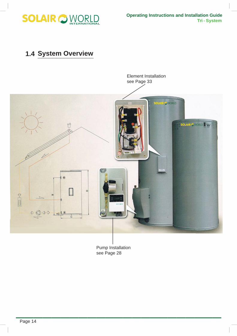
1.4 System Overview
Element Installationsee Page 33
Pump Installation see Page 28
_______________
Page 14

Operating Instructions and Installation GuideDucted System
_______________________Page
Section 2Installation Guide

Operating Instructions and Installation GuideTri - System
_______________________Page 1
2.1 Installation Overview
A
B
C
DE
DETAIL E
51 6114
System Components
1 Automatic air vent valve
2 Bush
3 15mm female tee
4 Union 15mm M × 15mm C
5 Sensor dry well
6 Hex nipple
7 Union 1" C × ½" M
8 Union conetite
DETAIL A
1
2
3
4
5
6
37
DETAIL B
8
System Components
1 Solar electric tank assembly
2 Solar collector
3 Back up element
4 Solar collector return pipe
5 Automatic air vent valve
7 Non return valve
8 Pump
DETAIL C SCALE 1 : 10
9
DETAIL D
10
DETAIL E
13 12 11
51 6114
System Components
9 End stop 1" conetite
10 Union 1" C × ½" C
11 24mm galvanised screw, self tapping
12 Bolt
13 Bracket - clamp
14 Solar heater rail
15 Nut
16Collector strap
1
2
4
5
7
9
10
9 Outdoor unit
10 Indoor unit
Exploded Diagrams
Exploded Diagrams
8
6
3
__________________

Operating Instructions and Installation GuideTri - System
_______________________Page 1
2.2 Removal and Placement of Tank
Removal of Existing TankThe existing tank (if applicable) should be drained and removed in a responsible manner.
Note: Do not drain on to grass or garden beds.
Placement of new tank
Safely position new storage tank on a level surface in accordance with all plumbing and building regulations.
Note: We recommend a plinth be heater where the water heater is subjected to
Refer to the section called “Rough In Diagram” on page 1 for detailed information on position of plumbing.
Water Connections
Using correct plumbing methods, connect the cold water pipe to thestorage tank.According to local regulations andall valves that are necessary e.g. tempering valves, pressur e limitingvalves, line strainer, duo valves, cold water expansion valves etc.
We recommend the use of new valves for all Installation. Refer to plumbing code and/or local requirements.The hot water line should be connected to the hot water outlet.
Hot water outlet
Cold water inlet
Installer’s GuideFull and detailed installation instructions are in the Installer’s Guide , included inside the water heater’s carton.
The water heater should be located as close as possible to the most frequently used hot water outlet. Ensure that the
data plate is clearly visible and provide adequate access for service to the thermostat, relief valve and anode.
Note : All models are equipped with a top cover. Allow 50% of the height of the water heater for clearance above to replace the anode.
be used where property damage could occur from water spillage. (See AS/ NZS3500.4 for further details.)
Note : Warranty does not cover consequential damage due to heater leakage.
Safety This appliance is not intended for use by persons (including children) with reduced physical, sensory or mental capabilities, or lack of experience and knowledge, unless they have been given supervision or instruction concerning use of the appliance by a person responsible for their safety. Children and animals should be supervised to ensure that they do not interfere with the appliance.
installed under the water
wet conditions.
____________________________

Operating Instructions and Installation GuideTri - System
_______________________Page 1
2.3 Tank Installation Requirements
This water heater must be installed by a licensed tradesperson, and in accordance with:
AS/NZS3500.4 “National Plumbingand Drainage Code Hot WaterSupply Systems – AcceptableSolutions”.
Clause G12 of the New Zealandbuilding code.
Local authority regulations.
Outside Australia and New Zealand,please refer to local plumbing andbuilding codes and regulations.
Notice to Victorian customers fromthe Victorian Plumbing IndustryCommission – this water heater mustbe installed by a licensed person asrequired by the Victorian Building Act(1993). Only a licensed person will
showing that the work complies withall the relevant Standards and only alicensed person will have insuranceprotecting their workmanship for 6years.
Water Supply PressureThis water heater is designed for direct connection to water supply pressures of no greater than:
All Models – 800kPa
Where the mains pressure can exceed
above, a pressure limiting device
in the cold water inlet supply. This device must be installed after the isolating valve and set below the pressure shown above. Note during periods of lower demand water pressure may increase.
Pool HeatingThis water heater must not be used for pool heating.
Pressure & Temperature Relief ValveThe Pressure & Temperature Relief Valve is supplied loose with the water heater. The valve rating is:
All Models – 1000kPa
The PTR valve must be installed directly into the top socket marked “RELIEF VALVE”. The drain line from this valve must run in a continuously downward direction in a frost-free ambient position with the discharge end left open to atmosphere permanently.
The PTR Valve is not intended to enable connection of the water heater to supplementary energy sources such as solar panels or slow combustion stoves (refer AS/NZS 3500.4 for guidance on these types of installations).
Open the PTR Valve for approximately 10 seconds by lifting the lever on the valve to ensure water is relieved to waste through the relief drain pipe. Lower lever gently and check that it closes correctly.
The PTR Valve must not be tampered with or removed. The water heater must not be operated unless this valve is
The PTR Valve should be checked for adequate performance or replaced at intervals not exceeding 5 years, or less in areas where local regulations apply.
Important: The PTR Valve and its drain outlet pipe must not be sealed or blocked. It is normal for the PTR valve to leak a small amount of water during heating cycles.
DangerFailure to operate the relief valve easing lever at least once every six (6) months may result in a problem with the water heater and in some cases the tank may explode.
Warning: A separate drain line must be run for this relief valve. It is not permitted to couple drain lines from relief valves into a single common drain line.
PTR valve
Plumb to waste to comply with AS/NZS 3500.4 and local plumbing codes
___________________________

Operating Instructions and Installation GuideTri - System
_______________________Page 1
2.3 Tank Installation Requirements
Cold Water ConnectionAn approved isolating valve, non return valve, line strainer (optional but recommended), and union must befiited between the sypply main and theRP¾”/20mm T fitting connected to the socket in the water heater.
relevant Authority and in accordance to the plumbing code.
Note: a combined isolating valve/non-return valve/line strainer may be used. Expansion valve only required where local regulations demand.
Note for S.A. and W.A.: It is a state requirement that a pressure relief valve
between the non return valve and the water heater.
Hot Water ConnectionThe hot water line should be connected to the “OUTLET” socket on the tank.
Note: Once all connections have been
the cold water inlet and bleed all lines according to appropriate plumbing code.
Safety InformationFor safe performance this water heater
an over-temperature energy cut-outthermostat
a combination Pressure &Temperature Relief Valve.
These devices must not be tampered with or removed. The water heater must not be operated unless both of thesedevices are fitted and in working order. The element cover should be removedonly by a qualified electrician. electrical power supply must be isolated at the main electrical supply switchboard before the water heater electrical cover is removed.
Insulation of PipesAll hot water pipes must be insulated with UV stabilized insulation suitable for solar working temperatures, e.g.
regulations regarding the use of hot water supply pipework other than pipes made of copper.
Temperature ProtectionAll solar water heaters have the ability to produce hot water very quickly. To reduce the risk of scald injury, it is mandatory under the requirements of Australian Standard AS/NZS3500.4:2003 that a suitably approved temperature control device be
used primarily for personal hygiene. This valve should be checked at regular intervals to ensure its operation and settings remain correct.
Note: This water heater is supplied with a tempering valve. Install the valve according to the manufacturer’s recommendations. Any adustments to the valve should be made according to the manufacturer’s recommendations.
The tempering valve should be checked at regular intervals to ensure its operation and settings remain correct.
___________________________

Operating Instructions and Installation GuideTri - System
_______________________Page
2.3
Pipes – Important
Critical: Due to the high temperature imposed by solar heated water, all solar system
brass and copper, including
(as supplied). No plastic pipes
Flow and return lines must beinstalled as direct as possiblebetween tank and collector.
Pipes must be fully insulated withUV stabilized insulation suitable forsolar working temperatur es. We
Solar insulation, minimum 13mmthick (refer to local regulations).
Note: Warranty will be void if this minimum insulation requirement is not used.
It is critical to stop any chance of anair lock developing, so ensure that:
– no pipework is higher than theautomatic air vent valve
Pipes must have no high points that allow air to be trapped
No pipes can be higher than the air bleed valve
–collectors to the water storage tankhave a minimum of 5° continuous fall
– pipes have no high points thatallow air to be trapped
– the minimum number of bends inthe pipes are used.
Flow and return lines should beneatly installed and hidden inside theroof cavity if possible.
and return lines through the roof,cladding and the eaves.
Note: Where roof and the eaves are made from asbestos, specialised handling and advice is necessary.
Minimum 5°continuous fall
To collectors
insulate flow and return pipes
Minimum 5°continuous fall
To collectors
Non continuous fall
To collectors
Incorrect Correct
Ensure flow and return pipes from the solar collectors to the water storage tank have a minimum of 5° continuous fall
Tank Installation Requirements___________________________

Operating Instructions and Installation GuideTri - System
_______________________Page
2.4 Panel Installation
Collectors – Alignment and Inclination
Solar Collector Alignment
collectors must be aligned ±45° from true north (i.e. north west to north east). See Collector Orientation Compass below.
Solar Collector Inclination
collectors must be inclined within 10° to 45° from horizontal. See Collector Inclination Guide right.
True North
NW
NE
Surface Plate
EastWest
45°
50° fromtrue north
70° fromtrue north
45°
B
Collector Orientation Compass
Note: When establishing the correct Collector Orientation, please account for the Magnetic Declination of your geographic location
C
A
C
A. Preferred rangeB. Industry accepted rangeC. If orientations A or B are not practical, an additional collector can be installed at the home owner’s discretion in range C (not required north of Tropic of Capricorn)
True North
A
A = 500mm, or greater if roof allows
B = Between 10° and 45°
B
Collector Inclination Guide
Collectors – Important Points
pressurized with water.
Critical: Fittings must be as tight as possible.
Warning: Only pressurize the the collectors for inspection and de-pressurize them immediately after inspection.
Critical: Do not leave collectors pressurised for lon ger than 24 hours.
To prevent damage, collectors should be left pressurisedonly when connected to the storage tank withappropriate pressure relief valves.Collectors can be located a maximum of 20 metres (with minimal bends)from the storage tank if pipe layout is simple.
Note: For more energy effciency, locate the collectors as close as possible to the tank
This system is suitable for 2 storey homes.
_______________

Operating Instructions and Installation GuideTri - System
_______________________Page
2.4 Panel Installation
Collectors – attaching to roof
For Both Metal and Tiled RoofsLocate the lower mounting rail aminimum of 500mm distance from the gutter, or greater if r oof allows.
Note: Ensure that the rail is parallel with the gutter.
For Metal Roofs Only
mounting straps on both sides, using rubber grommets to prevent corrosion.
screws of 40mm length must
strap to the truss.
Ensure that the rail is parallel with thegutter.
500mm or
greater
500mm or
greater
For Tiled Roofs OnlyCarefully remove a roof tile andlocate the nearest roof truss.
stainless steel collector strap to themounting rail.
Shape the collector strap over the tileand position over the roof truss.
screws of 40mm length must
strap to the truss.
Ensure collector strap is located ontruss vertically.
Repeat this process for the collectorstrap at the other end of themounting rail.
Once the bottom rail has beensecured, the collector can now belifted on to the roof.
Note: Ensure this is done with full consideration to OH&S regulations. Care should be taken.
Collector Strap
Collector Strap
Use minimum of 3 screws
_______________

Operating Instructions and Installation GuideTri - System
_______________________Page
2.4 Panel Installation
Collectors – attaching Fittings All connections must be brass and all
pipe work must be copper
header pipe. This is very important forcorrect connection.
To ensure leak proof installation, hold
while tightening nut B to preventtwisting the header pipe.
Critical: Do not use multi grips or similar tool, as you
Ensure you use the correct size spanner.
tight as possible on the barrel
coming loose.
Ensure the brass conetite compression fitting is installed in the correct direction
Hold fitting A while tightening nut Bto prevent twisting the header pipe
A B
Secure the collectors to themounting rail with the Z brackets,screws, nuts and bolts provided withthe water heater.
Repeat the process for the secondcollector.
Note: Ensure this is done with full consideration to OH&S regulations. Care should be taken.
Now position the top mounting rail andrepeat the above steps for that rail.
Join the top connections with the
Collectorstrap
Collectorclamp bracket
Collectormountingrail
24mm self tapping galvanised screw
_______________

Operating Instructions and Installation GuideTri - System
_______________________Page
2.4 Panel Installation
pipes to the collectors.
Ensure that you connect the solarn (hot)
pipes to the correct connections:
– to the bottom of the collectors
– the solar return (hot) pipe connectsto the top of the collectors,diagonally opposite to the solarcold pipe connection.
We suggest when you install pipesthrough roof, that you considercolour coding the pipe ends to show
Critical: During connection, the header pipe can move in the collectors. It is critical that the header pipe is centred to provide about 40mm of tube on both sides of the collector.
~40mm~40mm
4 Way Union assembly
Using correct plumbing methods,install the 4 Way Union assemblyand air bleed valve at the highestpoint in the system, at the top ofthe collector diagonally opposite thesolar collector inlet pipe.
The air bleed valve must standvertically straight towards the sky.
Note: If installed in top left/bottom right of collector, then T should be reversed.
assembly, we recommend Loctite577 Thr ead sealant and/or a good
air bleed valve. Tighten by hand. Donot use spanner .
Use Loctite 577 thread sealant or pink teflon tape to seal all threads
_______________

Operating Instructions and Installation GuideTri - System
_______________________Page
2.4 Panel Installation
Anti-Frost Valve
Consult the Map below to determine if your system needs an anti-frost valve.
If system is to be installed in the frost proven area, you must install an anti-frost valve.
However, TWO anti-frost valves must be installed if you live in alpine areas or areas subject to extreme frost.
The an ti-frost valve comes in kit form and must be ordered separately.
Frost Protection Installation Map
Wellington
Auckland
Christchurch
Locations in grey may be subject to frost.
_______________

Operating Instructions and Installation GuideTri - System
_______________________Page
2.4 Panel InstallationConnect the anti-frost valve to thetop collector connection, on theopposite collector to where thethermowell/air bleed valve is installed.
Ensure the valve is pointing down thecollector towards the gutter, parallelto the collector.
Flashing
As per local authority regulations,
Dektite or lead collars.
return lines penetratethe roof surface, the penetrationmust occur on the high side of the
Seal the roof penetration with
We recommend the use of theappropriate Dektite brand solar
steel roofs).
Flexible waterproofflashing
Roof penetration must be on high side of tile
Temperature Sensor
Insert the end of the collectortemperature sensor (supplied incollector rail kit) into the sensor drywell.
The sensor must be fully insertedand touch the end of the thermowell.
Firmly secure the sensor cable usingthe cable securing clip.
Cablesecuring clip
Collector temperature sensor
Sensor secured by clip
Warning: Extreme care must be taken to not damage the sensor by pulling on collector temperature sensor.
Warning: Install the sensor cable such that it does not
surface.
Warning: Conceal all temperature sensor cables in the roof cavity so that they are not exposed to sunlight or heat.
Warning: The collector sensor cable is a silicon rubber that may require additional conduit protection in extreme UV radiation conditions.
_______________

Operating Instructions and Installation GuideTri - System
_______________________Page 2
2.5 Controller Installation____________________
The Aestiva S1000 controller is differential controller specifically designed for forced circulation solar system.
The roof sensor is capable of operating under extremely high temperature.
The controller is user programmable with an access code and features intelligent self trouble shooting functions.Only authorized installers and technicians have access to the access code for reprogramming.The circulation pump is activated when the roof sensor temperature reaches a predetermined temperature
circulated water is then heated by the solar energy and then stored in the tank. An antifreeze function is available when the roof temperature falls below a predetermined figure. A small amount of water is circulated to the roof and effectively prevents frost damage.A manual pump operation is featured to allow user to temporarily turn on and off the devices by overriding the
It incorporates a microprocessor driven PCB board and a set of highly engineered thermal sensors.
higher than that of the lower tank sensor port. The
preset logic. However, the controller returns to auto mode after 2 hours in manual operation.
Each controller includes a built in self diagnosis detection and runs error checks continuously. hat needs replacing. All LED indicator
lights will flash to alarm the users.An error message will indicate the specific damaged sensor wire t
Mains Power
Pump Connection
Top Tank Sensor
Bottom Tank Sensor
Solar Panel Sensor

Operating Instructions and Installation GuideTri - System
_______________________Page
2.5 Controller Installation____________________
The controller base plate can be attached to either storage water tank or nearby wall. 4 mounting brackets are inbuilt in the controller base plate. The controller can be fit onto a specially designed pump station or nearby wall by fixing the mounting brackets onto 4 mounting studs or screws heads. Do not run sensor cables parallel to mains power cable and any additional wiring shall be coiled and shortened by qualified electricians.
Warning: The appliance is not intended for us by persons (including children) with reduced physical, sensory or mental capabilities, or lack of experience and knowledge, unless they have been given supervision or instruction concerning use of the appliance by a person responsible for their safety. Children must be supervised o ensure that they do not play with the appliance. This controller appliance is prewired with temperature sensor wires, power supply wire and output wires. During Installation, the power supply cord must not be allowed to connect with the main electricity supply, until the controller is securely in place and with all output connections already connected.
Optional Pump StationAestiva supplies a matching pump station for this S1000 controller. The pump station features fully Australian complied Watermarked brass wares, valves and fittings and a high quality Grundfos solar pump. The outer casing is injection moulded with UV additives to withstand Australian Outdoor conditions.

Operating Instructions and Installation GuideTri - System
_______________________Page
2.5 Controller Installation____________________
1. Mount controll box to the tank byfixing base plate to the tank withselftapping screws.
Screw HolesScrew Holes
2. Slide controll box onto thebase plate.

Operating Instructions and Installation GuideTri - System
_______________________Page
2.5 Controller Installation____________________
3. Sit pump into cradel on backingplate and connect power socketfrom control box.
4. Fix cover on.
Thread control box power cord from here

Operating Instructions and Installation GuideTri - System
_______________________Page
2.6 Controller Functions and Default Controller Setting
The controller has the following default functions/settings from factory.
Circulation pump differential control – The circulation pump will only be activatedwhen there is sufficient solar energy present on the roof to contribute to the heat gain in thewater cylinder. This is achieved by sensing the temperature difference between the roofcollector and inlet water temperature. The water circulation will stop when the roofcollector temperature falls and not sufficiently higher than the water cylinder inlettemperature.
”: 8 oC“Pump Differential On Temp “Pump Differential Off Temp ”: 2 oC
Top out protection – In good solar conditions, the solar collector could harvest the solarenergy extremely sufficiently and quickly raise the storage water cylinder temperature.The storage water cylinder internal lining may be damaged by the high temperaturewater, which can exceed the designed operating temperature range by the tankmanufacturer.The top out function prevents the water cylinder reaching dangerously hightemperature by stopping the pump circulation to the collector, so that the water is notheated further. A solar rated high temperature non return valve must be used in the solarloop in conjunction for maximum protection.
“Top Out Temp”: 75 oC“Top Out Reset Temp”: 73 oC
Anti -freeze protection – In frost conditions, the risers in flat plate collector or heatexchangers in evacuated tube collector may freeze and cause damages. Anti - freezeprotection can sense the roof temperature and activate the pump circulation for shortperiod before the water may freeze inside.
“Anti-freeze on Temp ”: 3 oC“Anti-freeze on Temp”: 5 oC
Manual pump function – During installation of the solar systems, a manually operatedsoar loop circulation is
Auto cavitation recovery – In case of drop of water pressure, air bubble may form andtrapped inside the
____________________________________________

Operating Instructions and Installation GuideTri - System
_______________________Page
2.7 Controller Basic OperationThe controller control interface consists of 4 buttons and 4 indicator lights and a white back lit LCD screen.
The controller is in automatic mode with the factory settings when it is turned on first. The screen will display all 3 sensors’ temperatures as below.
By pressing Manual pump button, the controller can be switched into manual mode. Other 3 buttons are only used during program mode, which requires an excess code from authorized personnel. During the program mode, using “Next” button, the controller will go through the following setting menus:
Using “+” and “ —“ buttons, the setting parameters can be increased and decreased.By holding the “program” button, the programming will be finished and the controller will reboot itself with the following prompt:
_______________________

Operating Instructions and Installation GuideTri - System
_______________________Page
2.8 Error Messages and Trouble Shooting
Faulty Sensors errors
Aestiva controller can check faults on faulty sensor itself. The solar loop operation will be stopped when a sensor error occurs. When one or more sensors are faulty, all 4 LED lights flash. The lower sensor display
If other sensors are faulty, the “Err” message will appear afterthe corresponding sensor on the screen.
Trouble shoot: Check the sensor cables casing condition or gently pull the cable from the controller to check for the connection with the terminals. If none works, please call up your installer for cable replacement.Do not run the sensor cable any AC wires, as interference may be caused.
Manual pump not working
Trouble shoot: Check the top tank temperature first by reading the controller screen. If the top out temperature has been reached, the controller will not allow the pump to manually operate to protect the tank.
The screen is blacked outTrouble shoot: Check for power supply first. Then the controller may be hit by a surge. The controller may be opened and the fuse should be replaced. This is best to be performed by an approved electrician.
_________________________________

Operating Instructions and Installation GuideTri - System
_______________________Page
2.9 Electric Connection____________________
SolAir World water tank is designed for single phase 22-24-V.A.C supply only. The eletric connection must comply with AS/NZS 3000. You can remove the electric cover easily after taking off 6 assemblyscrews.
Dangerous
1. The power supply must be protected by an individual circuit breaker at the main electricalsupply switchboard and rated to suit the booster size. The supply to the solar water heatercan be operated directly from the switchboard or via a remounted switch or time clock asrequested by the customer. The heater must be provided with a suitable means fordisconnecting the power supply.
2. Capacitance in the distribution panel should also be removed before removing the electriccover. When a twin element device is used.
3. Wire will be exposed after removing electric cover. So only the person who is licensed electricianis permitted to operate it.
4. Appliance not intended for use by persons (including children) with reduced physical, sensoryor mental capabilities, or lack of experience and knowledge that prevents them from using theappliance safely without superviseion or instruction: Children playing with the appliance.Children should be supervised by a person responsible for their safety to ensure that theydo not play with appliance.
5. There must be some water in the water tank berfore turning on the power supply.
6. Electric level of protection for water tank is desinged at IP34.
7. Any operation for electric connection must comply with AS/NZS 3000.

Operating Instructions and Installation GuideTri - System
_______________________Page
2.10 Electric Element and Thermostat____________________
The electric element has a capacity of 3.6Kw, coupled with a thermostat to control the water temperatureof the tank. This Solar Thermostat has an auto-reset over-temperature cut-out for high yield sunshine days, taking the boost heater out of circuit. It’s auto reset so you don’t have to get up on the roof to turn it back on.This OTC protects the system against no-fault over temperature tripping. When the water temperature in the tank reduces to a normal operating level, the auto reset occurs and the heater can once again use the booster heater. The thermostat is adjustable with a temperature range from 50°C to 80°C, you can rotate the redgear adjusting setting. The normal setting is 60°C.
The ST13-70 has a unique internal fuse, protection that is designed especially for Solar Water Heaters.This internal fuse is extra protection against any electrical malfunction, but it is a one use fuse.If the fuse activates, the thermostat will need to be replaced.
Photo of thermostat Wiring Diagram

Operating Instructions and Installation GuideDucted System
_______________________Page
Installation/Operating Manual for SolAir World's Thermal Air Conditioner
can be found in Head Unit carton.

Operating Instructions and Installation GuideTri - System
_______________________Page
Section 3Warranty Information

Operating Instructions and Installation GuideTri - System
_______________________Page
3.1 WarrantyGeneral1. The sell offers a 5-year warranty for the interior tank and 18- month warranty for the components and accessories
as from the shipment date. The seller bears only the cost of the guaranteed product.
2. The system must be installed by a licensed plumber and/or electrician in accordance with SolAir Worldinstallation instructions; and all relevant statutory and local requirements of the state or territory in whichthe system is installed.
3. The SolAir World water heater must be operated and maintained in accordance with instructions suppliedby SolAir World.
4. This warranty only applies to the water tank product and does not apply to any additional electrical and/orplumbing parts supplied by the installer.
5. The system is covered for the indicated period from the date of the original purchase. Should a part of thecomplete water tank component be replaced during this period, only the balance of the original warranty willContinue to remain effective. Proof of purchase is required.
6. The system should be installed in a domestic household.
7. Should this system be installed in a regional location where regular flushing is required due to sediment build-up,Then the drain cock for flushing must be fitted at the time of installation. If in doubt consult you plumbing.
8. Solar World system is excluded to the extent allowable by law from responsibility for any consequential lossIncluding: injury to persons, injury to property, economic loss, pain and suffering etc.
Exclusions1. Where service is required to reconnect the water tank operation due to problems related with abnormal water
Supply, faulty plumbing and/or electrical wiring, or major variations in electrical supply.
2. Where the system fails due to misuse, accidental damage, flood, acts of God, incorrect installation or unlicensedService repair work attempts.
3. Where system service is required due to the non-conformance with this warranty’s recommended maintenanceIn certain water quality conditions.
4. Claims for damage to walls, foundations, funishings, roofs or other losses, directly or indirectly due to th leakagefrom the water heater.
5. The manufacturer disclaims all responsibility for the loss or damage caused by any or all failures of tank thatextends its service life.
6. Damage or breakage is not covered by this warranty, and should be added separately to your general householdinsurance policy.
7. This warranty does not cover the effects of sludge/sediment as a result of connection to a water supply not unfilteredOr mineral content sources i.e. spring, dam, bore, river or other.
8. This warranty does not cover the effects of the connection of the appliance to bore waters and highly mineralizedWaters.
9. Where water stored in the cylinder exceeds the following levels: Total dissolved solids 600mg/kutre ir p.p.m Electrical conductivity 850us/cm Total Hardness 200mg/litre or p.p.m Chloride 250mg/litre or p.p.m
________

Operating Instructions and Installation GuideTri - System
_______________________Page 9
3.2 Installation Declaration
Location of Installation: ..........................................................................................
...............................................................................................................................
...............................................................................................................................
Tank Serial Number: ............................................................. ................................
Tank Model Number: .............................................................................................
Date Installed: ............................
Terms and conditions of warranty will apply only if the below is signed by the installer. This notifies the manufacturer that all the requirements of proper installation have been carried out by the installer in accordance with the Installer’s Guide, Owner’s Manual, and any other documentation supplied with the water heater.
Upon completion of installation, this document must be given to the home owner in its entirety. When required by the manufacturer, the home owner will provide this document as evidence that the installation of the water heater was carried out in accordance with installation requirements.
Declaration
I have installed the water heater in accordance with the above instructions. If the instructions have not been followed then I understand that the terms and conditions of warranty will be void.Name: ....................................................................................................................
Signed: ..................................................................................................................
Company: .............................................................................................................
Plumber’s Licence Number: ...................................................................................
Date: .........................................
____________________

Operating Instructions and Installation GuideTri - System
Page __________________
NOTES_______