An Embedded Linux Based Remote Control System · Abstract This project is an investigation into the...
60
An Embedded Linux Based Remote Control System Jonathan McCrohan B.A.I. Engineering April 2011
Transcript of An Embedded Linux Based Remote Control System · Abstract This project is an investigation into the...

An Embedded Linux Based Remote ControlSystem
Jonathan McCrohan
B.A.I. Engineering
April 2011

Declaration
I hereby declare that this thesis is entirely my own work and that it has not been submittedas an exercise for a degree at any other university.
Jonathan McCrohan4 April, 2011
i

Permission to Lend
I agree that the Library and other agents of the College may lend or copy this thesis uponrequest.
Jonathan McCrohan4 April, 2011
ii
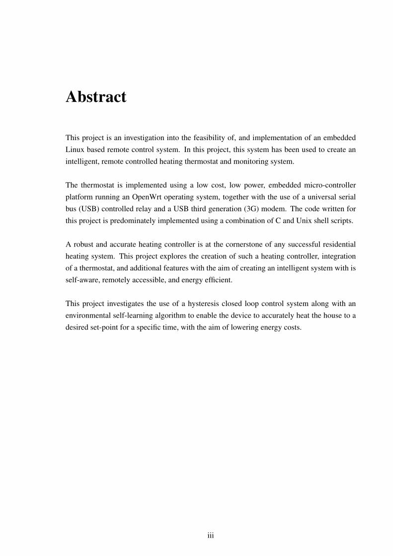
Abstract
This project is an investigation into the feasibility of, and implementation of an embeddedLinux based remote control system. In this project, this system has been used to create anintelligent, remote controlled heating thermostat and monitoring system.
The thermostat is implemented using a low cost, low power, embedded micro-controllerplatform running an OpenWrt operating system, together with the use of a universal serialbus (USB) controlled relay and a USB third generation (3G) modem. The code written forthis project is predominately implemented using a combination of C and Unix shell scripts.
A robust and accurate heating controller is at the cornerstone of any successful residentialheating system. This project explores the creation of such a heating controller, integrationof a thermostat, and additional features with the aim of creating an intelligent system with isself-aware, remotely accessible, and energy efficient.
This project investigates the use of a hysteresis closed loop control system along with anenvironmental self-learning algorithm to enable the device to accurately heat the house to adesired set-point for a specific time, with the aim of lowering energy costs.
iii

Acknowledgments
Firstly, I would like to thank my supervisor, Dr. Mike Brady, for his encouragement, adviceand guidance throughout this project. Thanks are also due to Ms. Bernadette Clerkin andMr. Shane Hunt from the Department of Electronic & Electrical Engineering for their helpwith the sourcing of, and soldering of the I2C temperature sensors used in this project.
I would like to thank Richard, Linus and the rest of the open source community, withoutwhom this project would not this possible.
Many thanks to my friends and colleagues who have supported me throughout this project.Their comments, both technical and humorous, have been appreciated.
Finally, I would like to thank my family for their support and encouragement and also for themany food parcels that were delivered to my room throughout this project. A special thanksgoes to my mother, Gwen, and my girlfriend, Sinead.
iv

Acronyms
3G third generation
68k Motorola 68000 architecture family
ADC analog to digital converter
API application programming interface
BSD Berkeley Software Distribution
CD-ROM Compact Disc Read-only memory
CF compact flash
CFD computational fluid dynamics
CGI Common Gateway Interface
CO carbon monoxide
CO2 carbon dioxide
CPU central processing unit
EEPROM Electrically Erasable Programmable Read-Only Memory
FSD full scale deflection
GCC GNU’s Not Unix! (GNU) Compiler Collection
GFCH gas fired central heating
GNU GNU’s Not Unix!
GPIO general purpose input/output
GPL General Public License
GSM global system for mobile communication
HEX hexadecimal
v

vi
HID human interface device
HTML HyperText Markup Language
HTTP HyperText Transfer Protocol
HVAC Heating, Ventilating, and Air Conditioning
I2C inter-integrated circuit
IANA Internet Assigned Numbers Authority
IC integrated circuit
IEEE Institute of Electrical and Electronics Engineers
IETF Internet Engineering Task Force
IP Internet Protocol
IPv4 Internet Protocol version 4
IPv6 Internet Protocol version 6
ISP Internet Service Provider
LCD liquid crystal display
MVC model view controller
NAT Network Address Translation
NDA non-disclosure agreement
NTP network time protocol
OFCH oil fired central heating
owfs 1-Wire file system
PoE power over Ethernet
PoP Point of Presence
ppm parts per million
PPP Point-to-Point Protocol
RAM random access memory
RC resistor capacitor
RIR regional Internet registry

vii
RTC real time clock
SCL serial clock
SDA serial data
SMS short message service
SoC System on Chip
SPARC scalable processor architecture
SPDT single pole double throw
SPI Serial Peripheral Interface
SSD solid state drive
SSH Secure Shell
TCP transmission control protocol
TTL transistor transistor logic
UART universal asynchronous receiver/transmitter
UCI unified configuration interface
UDP user datagram protocol
UMTS Universal Mobile Telecommunications System
URL uniform resource locator
USB universal serial bus
VAT Value Added Tax
XML eXtensible Markup Language

Contents
1 Introduction 31.1 Design . . . . . . . . . . . . . . . . . . . . . . . . . . . . . . . . . . . . . 4
1.1.1 Core Design Requirements . . . . . . . . . . . . . . . . . . . . . . 41.1.2 Desirable Design Requirements . . . . . . . . . . . . . . . . . . . 4
2 Background 62.1 Market Competitors . . . . . . . . . . . . . . . . . . . . . . . . . . . . . . 6
2.1.1 HeatSlave . . . . . . . . . . . . . . . . . . . . . . . . . . . . . . . 72.1.2 Netmonitor . . . . . . . . . . . . . . . . . . . . . . . . . . . . . . 72.1.3 EcoStarter . . . . . . . . . . . . . . . . . . . . . . . . . . . . . . . 7
3 Hardware 83.1 Mainboard . . . . . . . . . . . . . . . . . . . . . . . . . . . . . . . . . . . 83.2 ALIX 2D13 . . . . . . . . . . . . . . . . . . . . . . . . . . . . . . . . . . 93.3 Sensor Interfaces . . . . . . . . . . . . . . . . . . . . . . . . . . . . . . . 103.4 Relay . . . . . . . . . . . . . . . . . . . . . . . . . . . . . . . . . . . . . 133.5 LCD . . . . . . . . . . . . . . . . . . . . . . . . . . . . . . . . . . . . . . 143.6 CO2 Sensor . . . . . . . . . . . . . . . . . . . . . . . . . . . . . . . . . . 143.7 Arduino Datalogger . . . . . . . . . . . . . . . . . . . . . . . . . . . . . . 16
4 Networking 194.1 Hayes AT commands . . . . . . . . . . . . . . . . . . . . . . . . . . . . . 204.2 SMS . . . . . . . . . . . . . . . . . . . . . . . . . . . . . . . . . . . . . . 214.3 TCP/IP . . . . . . . . . . . . . . . . . . . . . . . . . . . . . . . . . . . . 21
4.3.1 IPv4 NAT Traversal . . . . . . . . . . . . . . . . . . . . . . . . . 224.4 Concurrent TCP/IP and SMS . . . . . . . . . . . . . . . . . . . . . . . . . 26
5 Software 275.1 OpenWrt . . . . . . . . . . . . . . . . . . . . . . . . . . . . . . . . . . . 27
5.1.1 BusyBox . . . . . . . . . . . . . . . . . . . . . . . . . . . . . . . 285.1.2 UCI . . . . . . . . . . . . . . . . . . . . . . . . . . . . . . . . . . 28
5.2 uHTTPd . . . . . . . . . . . . . . . . . . . . . . . . . . . . . . . . . . . . 295.2.1 LuCI . . . . . . . . . . . . . . . . . . . . . . . . . . . . . . . . . 29
1

CONTENTS 2
5.3 huaweiaktbbo . . . . . . . . . . . . . . . . . . . . . . . . . . . . . . . . . 305.4 heatingcontroller . . . . . . . . . . . . . . . . . . . . . . . . . . . . . . . 305.5 GNU Screen . . . . . . . . . . . . . . . . . . . . . . . . . . . . . . . . . . 315.6 i2c-tools . . . . . . . . . . . . . . . . . . . . . . . . . . . . . . . . . . . . 315.7 lcd4linux . . . . . . . . . . . . . . . . . . . . . . . . . . . . . . . . . . . 325.8 autossh . . . . . . . . . . . . . . . . . . . . . . . . . . . . . . . . . . . . 335.9 temper . . . . . . . . . . . . . . . . . . . . . . . . . . . . . . . . . . . . . 335.10 phidget004 . . . . . . . . . . . . . . . . . . . . . . . . . . . . . . . . . . 335.11 minicom . . . . . . . . . . . . . . . . . . . . . . . . . . . . . . . . . . . . 335.12 comgt . . . . . . . . . . . . . . . . . . . . . . . . . . . . . . . . . . . . . 335.13 e2fsck . . . . . . . . . . . . . . . . . . . . . . . . . . . . . . . . . . . . . 34
6 Monitoring 356.1 Arduino . . . . . . . . . . . . . . . . . . . . . . . . . . . . . . . . . . . . 356.2 Data Analysis . . . . . . . . . . . . . . . . . . . . . . . . . . . . . . . . . 37
6.2.1 Optimum Start Algorithm . . . . . . . . . . . . . . . . . . . . . . 376.3 Failure Detection . . . . . . . . . . . . . . . . . . . . . . . . . . . . . . . 38
7 Review and Conclusion 407.1 Areas of Possible Improvement . . . . . . . . . . . . . . . . . . . . . . . . 40
7.1.1 Reimplement in C . . . . . . . . . . . . . . . . . . . . . . . . . . 407.1.2 Reimplement sensors using 1-Wire + owfs . . . . . . . . . . . . . 407.1.3 Implement Web application programming interface (API) . . . . . 417.1.4 OpenTherm Support . . . . . . . . . . . . . . . . . . . . . . . . . 41
7.2 Failings . . . . . . . . . . . . . . . . . . . . . . . . . . . . . . . . . . . . 417.2.1 Lack of Hardware Hard Reset . . . . . . . . . . . . . . . . . . . . 417.2.2 Lack of udev support . . . . . . . . . . . . . . . . . . . . . . . . . 417.2.3 Serial universal asynchronous receiver/transmitter (UART) . . . . . 42
7.3 Successes . . . . . . . . . . . . . . . . . . . . . . . . . . . . . . . . . . . 427.3.1 Network Address Translation (NAT) Traversal . . . . . . . . . . . 427.3.2 temper . . . . . . . . . . . . . . . . . . . . . . . . . . . . . . . . 427.3.3 OpenWrt patches . . . . . . . . . . . . . . . . . . . . . . . . . . . 427.3.4 Deeper understanding of Linux kernel . . . . . . . . . . . . . . . . 427.3.5 Concurrent SMS + PPP Connections . . . . . . . . . . . . . . . . . 43
7.4 Conclusion . . . . . . . . . . . . . . . . . . . . . . . . . . . . . . . . . . 43
Bibliography 46
A Code Listing 47A.1 /etc/heatingcontroller/process new messages.sh . . . . . . . . . . . . . . 47A.2 /etc/heatingcontroller/schedule.sh . . . . . . . . . . . . . . . . . . . . . . 50A.3 /etc/config/heatingcontroller . . . . . . . . . . . . . . . . . . . . . . . . . 52

Chapter 1
Introduction
The aim of this project is to investigate the feasibility of, and implementation of a Linuxbased remote control system. As a proof of concept, it was decided to use this to create aheating thermostat.
This heating controller aims to to have two distinguishing features:
AccessibilityHeating thermostats have traditionally had simple user interfaces. These generallyprovide a simple on-off functionality, and optionally, a timed scheduler. This projectaims to provide a thermostat with a better user interface. In this project, a numberof interfaces have been explored including short message service (SMS), HyperTextTransfer Protocol (HTTP), command line, and liquid crystal display (LCD).
The aim of this is to provide a system which provides the user with a superior userinterface than is currently available.
Energy EfficiencyThermostats are closed loop control devices which provide regulated heat output to anenvironment. Thermostats monitor the environment for energy losses and gains, andactuate the heating output as required. Thermostats provide high levels of comfort tousers than traditional heating controllers, and are energy efficient when used correctly.
While industrial heating controllers today commonly include thermostat functionality,the majority of household heating controllers do not contain thermostats, and as such,are not energy efficient. Regular heating controllers allow users to inadvertently over-heat or underheat their building, which requires additional energy, or energy dumpingto rectify. By creating a thermostat controller, householders can define a comfortablesetpoint, at which the device aims to keep the temperature. This conserves energy bymaintaining a steady temperature, and avoids overheating the house.
3

CHAPTER 1. INTRODUCTION 4
1.1 Design
A heating controller system has a number of core requirements. These core requirementswere used to obtain solutions to the problems that arose from the design stages. Secondaryto this, a successful heating controller system has a number of lesser important, desirablerequirements, along with features that would be useful, although are not critical to the design.
These requirements can be split into core and desirable requirements as follows:
1.1.1 Core Design Requirements
ReliabilityThe system must be reliable. Users must be able to place their trust in this device, andhave confidence that it will not malfunction. The system must be capable of detectingmalfunctions and take appropriate steps to rectify these issues.
Accurate TimingThe system must contain a relatively accurate hardware backed-up clock. While com-puter systems are generally not required to have overly accurate system clocks dueto network time protocol (NTP) synchronisation servers, a network failure can renderthis system liable to clock drift. This is compounded by the risk of a power failureresetting the system clock to the unixtime epoch. While the presence of a real timeclock (RTC) is beneficial to ensure resilient operation after a power failure, it is notstrictly necessary due to NTP and SMS network time. A prolonged period of networkdowntime is unlikely. Given that a NTP synchronisation takes milliseconds, a singlesynchronisation should provide accurate timing for at least three months. In a worsecase scenario, it is possible for the the system to synchronise itself using the timestampprovided by a SMS message. Upon detecting a false RTC the system can send itself aSMS to retrieve the timestamp.
Failsafe OperationThe system should fail in a predictable manner, avoiding a situation where a heatingsystem is locked in an always on, unsafe state. The use of a watchdog timer should beinvestigated if provided by the board.
Low CostThe system should not cost a disproportional amount compared to existing heatingcontrollers, but the system should also allow future expansion so that future retrofitsare not prohibitively expensive.
1.1.2 Desirable Design Requirements
Remote AccessRemote access to this device is desirable. Remote access via SMS and HTTP enables

CHAPTER 1. INTRODUCTION 5
the device to be programmed remotely, without requiring a human to be present tomanually program the device. While this can seen be seen as a luxury feature by many,it also has important applications in the area of assisted living, and eHealth. Remotecontrol of a heating system can allow people to gain a more independent lifestyle,without requiring obtrusive check-ups from relatives.
Multi PlatformIt is envisaged that this system, or a similar system will be deployed as a standardfeature within the home in future years. In order to maximise this system’s audience,it is desirable to keep this system as device agnostic as possible, allowing people torun a system like this on many different architectures and modem models.
Integration with Household DevicesGiven the increasing trend of intelligent devices around the home, it would be advan-tageous to investigate whether these devices could be merged, or made to interact inan intelligent fashion to provide each other with environmental data.
Remote MonitoringRemote monitoring can be used to allow this device to function as a self publishingdata sensor device. This allows the device to collect, collate and publish its own sen-sor information. This is a byproduct of the modem required for remote access. Theuse of standard, self-documenting, data exchange formats such as eXtensible MarkupLanguage (XML) should allow the data to be integrated easily into a new or existingsystem.
In Field UpgradabilityThe ability to modify or remotely upgrade the software on the device is desirable. Thisallows the maintainer to increase functionality or to fix bugs without needing accessto the physical device. This aims to cut the costs associated with providing after salesupport. The use of open source software can enable users to maintain, fix and upgradethe software long after the original support schedule of the original company.
Inevitably, it was not possible to meet all of these design requirements. However, asmany of these as feasible were incorporated into this device.

Chapter 2
Background
Moore’s Law describes a trend in the semiconductor industry whereby the number of tran-sistors per integrated circuit has approximately doubled every two years [15]. With Moore’sLaw both describing, and driving the semiconductor industry for the best part of forty years,microprocessors are now small enough and cheap enough to be embedded in many devicesaround the home. These devices such as routers, set-top boxes and security cameras are oftenvery capable devices in their own right, and consequently spend most of their time idle. Thisproject aims to explore the feasibility of producing a remote control and monitoring sys-tem that can be integrated into an existing embedded Linux system to produce an advancedhousehold heating controller. While most of the homes built in Ireland in the last ten yearsnow come with digital on/off/timer heating controllers, the majority of existing householdsstill contain a mechanical on/off/timer heating controller, which must be physically switchedon or off. Neither of these systems is capable of remote access or of providing the user withinformation on their usage patterns.
The move towards digital controllers, does, however, allow manufacturers to provideintelligent interfaces to their devices, and allows these heating controllers to interact withother digital devices such as desktop computers, smart phones and home automation devices.By integrating these devices, the user can be provided with feedback on their usage habitswhich allows the user to control the heat, and ultimately, allowing the user to modify theirusage patterns to more effectively reduce energy consumption, reduce costs, and increasecomfort.
Most of these advances have been seen in the industrial heating controller market. Therehas been little advance in the home sector, and this proof of concept device explores the via-bility of providing these industrial features to the home user with additional comfort featuressuch as remote access.
2.1 Market Competitors
The market competitors were investigated during the course of this project, and it was foundthat there were very few products aimed at the home market.
6

CHAPTER 2. BACKGROUND 7
2.1.1 HeatSlave
HeatSlave is a SMS based heating controller from a Scottish company called VVS Technol-ogy LTD. This device provides remote access to the heating controller through the use ofSMS, and indirectly through the use of a HTTP interface on the HeatSlave website. Thisdevice currently costs e185.00 ex. VAT at time of writing. Although this device does notprovide thermostat functionality, it is capable of monitoring the temperature and sending amessage to the operator once a set-point has been reached, allowing the operator to manuallytake appropriate action.
2.1.2 Netmonitor
Netmonitor is a heating thermostat from an English company called Heatmiser UK LTD.This device provides dual interfaces, providing both SMS and HTTP interfaces to controlthe heating and up to 6 auxiliary devices. This device currently costs £492.00 inc. VAT.
2.1.3 EcoStarter
EcoStarter is a heating thermostat from Hulaas IT Solutions, a Swiss company. This deviceprovides features similar to the Netmonitor device, but contains a much more polished touchscreen user interface, and provides a dedicated smart-phone interface for use with iOS andAndroid smart-phone devices. The EcoStarter device uses a wireless interface to allow thedevice to control the output of up to sixty-four relay plugs connected to the system. Theenhanced features of this device are reflected in the price of e899.00 inc. VAT.

Chapter 3
Hardware
3.1 Mainboard
The GNU/Linux operating system has been ported to a plethora of operating systems, in-cluding x86, AMD64, SPARC, 68k, ARM, Itanium, MIPS, PowerPC amongst others. Thisflexibility meant that the decision on which hardware system to use was not influenced by theoperating system. A reliance on traditional operating systems such as Microsoft Windowsor Apple Mac OS X would have restricted the range of possible architectures to x86, x86-64,PowerPC and Itanium architectures only. Out of these architectures, only x86 is generallyused in embedded devices, and at that, faces stiff competition from other lower power archi-tectures such as ARM and MIPS. According to a 2008 survey of embedded engineers, Linuxwas used by 18% of respondents, making it the most popular embedded operating systemas the time of the survey [13]. This trend is expected to continue in coming years given thedominance of Google’s Linux-based Android operating system in the smartphone embeddedsector.
During the hardware decision process, many factors were considered:
Low CostThe aim of this project is to create a low cost monitoring platform and therefore, thecost of the base hardware should be kept as low as possible.
RTCThe presence of a RTC on the board is vital. The device must be capable of operatingin the absence of a network connection. Given that most embedded systems do notpossess a RTC, a network connection is required to set the correct time via NTP server.A situation where the heating controller malfunctions because of a power failure isclearly undesirable.
Schematic DiagramsDue to the fact that the system is to be used as a sensor monitoring device, it is im-perative that there is easy availability of the necessary schematics for interfacing with
8

CHAPTER 3. HARDWARE 9
the board. These should be easily located on the Internet, preferably provided directlyfrom the manufacturer.
InterfacesIn order to interact with the various sensors required to monitor the local environment,the presence of many data interfaces is essential. During the decision process, varioussensor interfaces such as I2C and 1-Wire were explored.
Robust DesignIn order for the system to survive in a difficult environment where there is likely to beaccidental knocks and other unavoidable damage, it is vital that the system possess arobust housing.
ReliabilityGiven that the system is designed to be installed remotely, where physical access isoften not possible for long periods of time, a proven, reliable hardware platform isrequired.
OpenWrt SupportIn order to increase portability between other embedded systems, it was felt that itwould be best to use OpenWrt for the operating system. A board that was alreadysupported by OpenWrt would be advantageous compared to having to port OpenWrtto a new board prior to commencing this project. OpenWrt is discussed in furtherdetail in section 5.1.
PrototypingIt is vital that the system provides an easy recovery mechanism to recovery from a badimage flash, or erroneous software configuration files. During the initial design phase,it is inevitable that these errors will occur, and a quick and easy method of recoveryis desirable. Traditional embedded recovery methods such as JTAG are slow, and cantake a number of hours to recover a bricked device.
3.2 ALIX 2D13
In light of these requirements, it was decided to purchase an ALIX 2D13 mainboard fromPC Engines.
This mainboard is powered by a 500 MHz AMD Geode LX800 processor, and pro-vides 256 MB of RAM. A compact flash (CF) slot is provided for use as a primitive solidstate drive (SSD). The mainboard is equipped with an on-board RTC and backup battery.The mainboard uses inter-integrated circuit (I2C) internally for a thermal monitoring chip(LM86), and conveniently provides breakout pins for an I2C header.

CHAPTER 3. HARDWARE 10
The mainboard also provides 3 Ethernet ports which could be used to provide Internetaccess to other devices around the area, or for monitoring remote areas. Due to the way inwhich power over Ethernet (PoE) support is implemented on the ALIX board, it is possibleto provide power and TCP/IP to remote devices via a single CAT5 cable. This feature wasoriginally designed to allow the ALIX board to be powered via Ethernet, but the wiring con-figuration also allows the device to act as a PoE power source. The unused pairs in the T568Aand T568B wiring schemes, pairs 2 and 3, are connected to VCC and Gnd respectively. This,in effect provides PoE functionality.1
As the project progressed, it became more apparent that this board was very much overspecified for the task at hand. The total random access memory (RAM) usage for the heatingcontroller system was 10 MB, roughly 4% of the available system memory. A similar situa-tion existed for the file-system. The total file-system usage for the heating controller systemwas 19 MB. It must be noted however that this is the uncompressed size. Through the use ofa compressed file-system such as squashfs, it should be possible to fit this file-system on toa 8 MB flash device, or failing that, a 16 MB flash device.
3.3 Sensor Interfaces
Much thought and consideration was given to the type of sensor interface chosen for thesystem. Various protocols exist, each with its own advantages and disadvantages. The mainones in use today are:
I2CI2C is a short distance, low-bandwidth serial data bus, which has gained broad accep-tance in circuit applications and become a common sight on modern computer moth-erboards. I2C nodes function in a master-slave relationship, which supports multiplemasters. This enables any node to potentially interact with any other node. I2C usesjust two signals to communicate with the bus. These are the serial data (SDA) andserial clock (SCL) lines respectively. I2C operates at approximately 100kbps. I2C net-works are commonly used for temperature monitoring in computer hardware, with theNational Semiconductor LM75 series commonly being used for this purpose.
One of the flaws of I2C is a relatively small addressing space. The I2C specificationallocates 7 bits for addressing. This would normally allow 128 nodes per network. Thisis hindered by the fact that most I2C device manufacturers generally assign addressesbased on device type, rather than unique per device. This makes it impossible to useidentical devices on the same network. A number of manufacturers overcome thisproblem by providing floating pins which may be tied high, or low to vary the devicesaddresses [18].
1While this is not IEEE 802.3af-2003 compliant, it is more than enough to provide power to remote sensordevices.

CHAPTER 3. HARDWARE 11
1-WireThe 1-Wire protocol was originally designed to allow micro-controllers interface withperipherals using only a single microprocessor port pin. 1-Wire uses a single wireground return wiring scheme, which, despite its name, actually requires a minimum oftwo wires to function, DQ and GND. The data line (DQ) is bidirectional, and transmitsthe data between the 1-Wire device and the master. 1-Wire devices are powered eitherby providing a third wire, VCC, or by through its DQ line. The latter, known as parasiticmode, uses an internal resistor capacitor (RC) circuit to power the device when the DQis transmitting data.
As 1-Wire devices became more popular, efforts were made to improve the 1-Wireprotocol’s networking applications. This has enabled 1-Wire to be used for generalenvironmental monitoring, in addition to their designed purpose of motherboard hard-ware monitoring. The 1-Wire addressing scheme is far superior to that of I2C, witheach device provided with a globally unique 64-bit serial code [12].
ModbusModbus is an industry orientated application-layer messaging protocol designed byModicon in 1979 for use with programmable logic controllers. Modbus is a simple androbust protocol, which generally operates using RS-485 differential signalling whichaffords it good noise immunity [14]. Modbus has good Linux support through theuse of libmodbus, and open source C library. While there are no royalties associatedwith using the Modbus protocols, it was found that manufacturers generally chargea premium for Modbus devices over other protocols. This is presumably due to theadditional hardware required to support Modbus.
ZigBeeZigBee uses small, low-power digital radios operating in the 2.4GHz ISM band to cre-ate a network for low data rate, long battery life, and secure networking applications.Zigbee is based upon IEEE 802.15.4, and consequently supports peer-to-peer and startopologies [9].
Having considered the environment that the heating device was to be used in, it wasdecided to use I2C based sensors. This decision was also influenced by the fact that theALIX 2D13 board had a readily available I2C header and Linux support.
After examining the devices available on the market, it was found that there were notmany available, and only one device family actually fitted the specification requirements.This was the Maxim MAX6633/4/5 I2C temperature sensor family. These devices provide 4,3 and 2 pins respectively for addressing purposes. This allows many identical devices to op-erate on the same I2C bus with unique addresses. The exact device used was the MAX6634,which provides 3 address pins. This allows for 8 sensors on the I2C bus.

CHAPTER 3. HARDWARE 12
In hindsight, this use of I2C proved to be naive, and ultimately, restricting. A lack ofproper documentation regarding the Linux I2C support prevented a C-based program frombeing written to interact with the thermometers. This proved to be very restricting, and meantthat interaction with the I2C sensors had to be done through the use of the i2ctools packageand shell scripts. The i2ctools package did not appear to fully support the MAX6634 devices,with seemingly random data being returned for most modes of operation.
After much examination, it was discovered that i2ctools was actually returning meaning-ful data, albeit in a jumbled form. When the temperature sensor was outputting a hexadecimal(HEX) value of 0x1234, the i2ctools program was outputting a HEX value of 0x3412. Thereason for this was not fully determined, but it would appear to be an issue with the endi-anness of either the I2C bus or the conversion program. This had originally been dismissedas a possible theory due to the fact that the order of the bytes was not totally reversed. Thiswould have suggested a conversion from little endian to big endian or vice-versa, and wouldhave expected an output of 0x4321.
It was only after revisiting the problem after a number of months that it was discoveredthat the output of 0x3412 was, in fact, correct. Each HEX character represents one of 16values, and hence can be represented using 4 bits. Given that memory and CPU registers arebyte-addressable, it is quite possible that only the order of the bytes will be reversed, and noteach individual nibble2. This would account for this odd behaviour.
Figure 3.2: Endian issues encountered.
Given the difficulties encountered with the software, and the lack of suitable weatherproof enclosures available for the I2C devices, it was felt that an alternative sensor deviceshould also be explored, namely the pcsensor.com TEMPer1. The TEMPer1 device is a USBdevice with the temperature sensor encased in a waterproof probe. This is vital for the exter-nal temperature readings which are required to efficiently preheat the house. The TEMPer1device is a human interface device (HID), and as such, falls into the same USB device cate-gory as keyboards and mice. The device can be accessed from Linux using libusb3. An opensource program called temper was found on the Internet to interact with this device, and thisis discussed further in section 5.9.
1-Wire was also considered when choosing a mainboard, but it was found to be difficultto source an industrial board with a 1-Wire interface. The I2C headers provided by the ALIXdevice were a predominant factor in the decision to use an I2C bus rather that a 1-Wire bus.
2A nibble is a group of 4 bits, and hence, can be represented by a single hexadecimal digit.3libusb aims to provide user level access to system level USB devices.

CHAPTER 3. HARDWARE 13
This was an error, and the project will most likely use a 1-Wire based bus in future revisions.This is due to the superior integration of 1-Wire within Linux userspace applications. 1-Wire’s superior addressing capabilities also allow for the greater number of sensors to beplaced around the home, with an aim to increase the accuracy of the system. With the adventof newer USB to 1-Wire interface integrated circuits (ICs) such as the Maxim4 DS2490,it appears that hardware support for 1-Wire is becoming less important. The move to aUSB based system allows increased support for these devices given that USB is virtuallyubiquitous. In the event of a device lacking USB ports, it is also possible to create a 1-Wireinterface using unused serial, parallel ports or 2 unused general purpose input/output (GPIO)pins. The availability of dedicated weather proof 1-Wire temperature sensors suggests that itwould have been a far better choice compared to the current I2C based solution.
3.4 Relay
In order to control the power to the oil fired central heating (OFCH)/gas fired central heating(GFCH) burner, a relay was required. This could be controlled by either:
• a spare GPIO pin on the central processing unit (CPU) brought out to a transistortransistor logic (TTL) level relay.
• a relay with an on-board microcontroller providing an USB interface.
With efforts to increase the flexibility of the system in mind, it was decided to use a USBrelay. A 4 output single pole double throw (SPDT) USB relay was sourced from PhidgetsInc. The model, a PhidgetInterfaceKit 0/0/4, provided an interface library and example codefor many languages, including C. This was helpful during the efforts to interface the relaywith the OpenWrt board. The relay is capable of switching up to 10 amps at 250 volts ofalternating current, making it safe for use with standard Mains voltage in Ireland, as well asup to 5 amps at 100 volts of direct current. SPDT relays provide two outputs, one that isclosed when the relay is unpowered, and one that is open the relay is unpowered. These arereferred to as NC and NO outputs respectively.
During the duration of the project, it was found that the Phidgets relay device couldbecome unresponsive under certain circumstances. A series of commands sent to the devicein rapid succession caused the device to malfunction, and require a system reboot. Thiswas problematic, and required a rewrite of the scheduler software to ensure that only onecall could be made to the device at any time. The use of a GPIO controlled relay wouldhave increased reliability, but this is hindered by unpredictable start up and reset sequences.Each CPU family responds differently to halt, low voltage and reset cases. Should a GPIOcontrolled relay be used, these corner cases must be thoroughly investigated to ensure thatthe GPIO pin does not become locked in an undetermined state, resulting in undesirableoutput being propagated to the relay and consequently the heating system.
4Formerly Dallas Semiconductor

CHAPTER 3. HARDWARE 14
The software used to interface with the relay is discussed in section 5.10.
3.5 LCD
The user interface for a heating controller device like this is very important. It is critical thatthe device provides the user with the information they require in an intuitive and accessibleway. Conversely, it is important that the user is not provided with too much information, asthis may confuse the user. Given that the system is to be installed in a family household, itis imperative that the system is accessible to all householders, regardless of prior technicalknowledge.
In light of the considerations above, it was decided to purchase a HD44780 CharacterLCD screen. The HD44780 family of LCD screens (originally released by Hitachi, but sincecloned by other manufacturers), has become the de-facto standard LCD interface [10]. Inter-action with these LCD screens is through the use of a 4 or 8 bit parallel data bus. Therefore,in order to conserve processor GPIO pins, and to make the platform as hardware agnostic aspossible, it was decided to use HD44780 screen with a dedicated USB to HD44780 data busconverter.
The software used to control this LCD, lcd4linux, supports only a limited number ofLCD protocols, one of which is the Matrix Orbital protocol. This protocol was originallydesigned by Matrix Orbital for use with their own LCD devices, but has since been reverseengineered for use with other devices.
It was planned to program a Microchip PIC or Atmel AVR micro-controller device toimplement a Matrix Orbital compatible USB to HD44780 converter, but this idea was aban-doned when it was discovered that Sure Electronics sell a HD44780 LCD screen with a Ma-trix Orbital compatible USB to HD44780 micro-controller attached for a reasonable priceof $15. In light of this, it was felt that it was not worthwhile to reverse engineer the MatrixOrbital protocol. The Sure micro-controllers contain a reverse engineered version of the Ma-trix Orbital command protocols, and consequently are supported within Linux by lcd4linux.This is discussed further in section 5.7.
3.6 CO2 Sensor
A MB Technik KCD-AN300 0-2000 ppm carbon dioxide (CO2) sensor was purchased toenable this project to demonstrate its application in the eHealth and monitoring sector. CO2
is an invisible gas, making up 10% of the environment and is produced by the Human bodyas a by product of respiration. CO2 is generally measured in parts per million (ppm).
The average for fresh, clean air is 800 ppm. While CO2 is harmless in 800 ppm doses,it is toxic in larger concentrations. Levels above 5,000 ppm are considered unhealthy, whilelevels of 10,000 ppm can cause drowsiness. Levels of 70,000 to 100,000 ppm can causeheadache, dizziness, visual and hearing dysfunction, and can lead to unconsciousness. This

CHAPTER 3. HARDWARE 15
has lead to CO2 concentration being used as common indicator of indoor air quality, withvalues between 300 and 2,500 ppm being deemed as acceptable.
The use of a CO2 sensor is designed to allow users to monitor the air quality in their homeremotely, but also allow this device to function as a warning device for carbon monoxide(CO) that may be emitted from the gas/coal fired heating burner. While this specific devicedoes not monitor CO, a similar model exists, and is available from MB Technik. This productis a slot in replacement for the CO2 device used in this project.
The KCD-AN300 CO2 sensor provides both 0-5V and 0-10V analog output as well as aTTL level serial UART for interfacing with the board. It was envisaged that this device wouldinterface with a Microchip MCP3426A0 I2C analog to digital converter (ADC), but this washindered by both a lack of support in the i2c-tools package, and voltage level conversionproblems.
The I2C header on the ALIX board provided a VCC voltage of of 3.3 V. This is withinthe operating thresholds of the MCP3426A0, however, it was not noticed until assemblytime that the maximum full scale deflection (FSD) of the ADC is determined by the voltagedifference between the supplied VDD and VSS. This limited the ADC to reading voltagesbetween 0 and 3.3 V, which was problematic given that the CO2 sensor was capable ofoutputting 1.7 V greater than this under normal operation. This would restrict the CO2
sensor to readings of less than 1320 ppm. A reading of 1320 ppm is a reasonable value for apoorly ventilated room, and clearly this design was not acceptable.
While the ADC itself is capable of FSD voltages of upto VDD + 0.3 V, it was unpracticalto use 3.3 V to 5 V level converters between the ADC and the I2C interface. In order tosupport a 5 V FSD, it would be necessary to restrict the device to mainboards using a 5V I2C header. Upon investigation, it was found that while the original I2C specificationrequired 5 V logic, modern revisions support voltages as low as 2 V. Given modern trendstowards lower power devices, it is not feasible to support a device which was going to losecompatibility and accuracy as I2C voltages are lowered.
In addition, difficulties were encountered with i2ctools when interfacing this device withthe system. The data outputted by the program was again, like the I2C temperature sensors,nonsensical. Given the difficulties encountered when interfacing the temperature sensors, itwas decided to abandon this avenue of exploration and concentrate on interfacing the CO2 viathe UART. This avenue was more successful and successfully allowed the CO2 measurementto be read by the board.
This was not without trouble however, as the TTL level serial port provided on the ALIXboard would not work with the CO2 UART. The reason for this was never fully determined,but it was possible to get both the CO2 UART and the ALIX serial port working indepen-dently of each other using other devices. In order to get the devices to interface correctly, itwas necessary to use a FTDI USB to serial interface chip. This chip had no issues connectingto the CO2 UART and enabled the board to interface with device at the cost of a USB port.

CHAPTER 3. HARDWARE 16
3.7 Arduino Datalogger
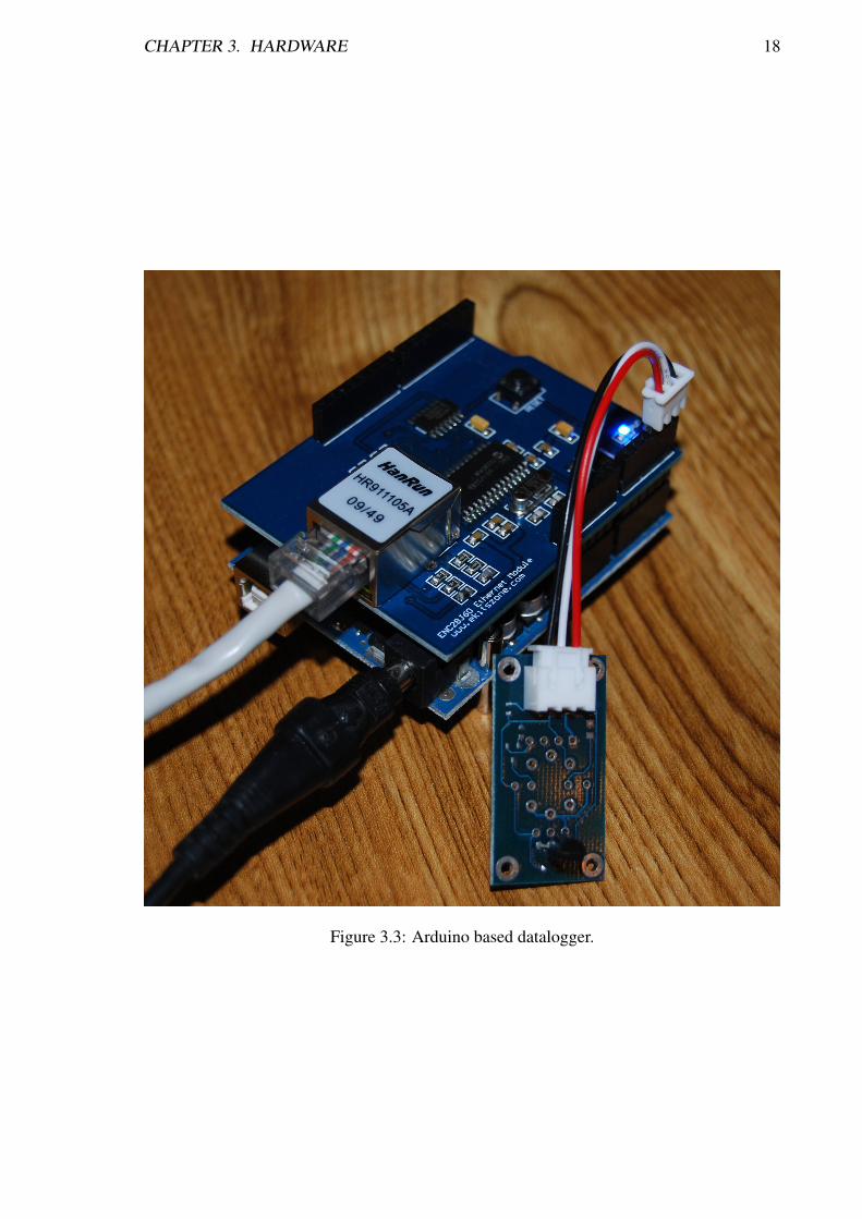
In order to gather the temperature measurements required for preheat analysis, it was neces-sary to build a robust platform for logging the data. These measurements were recorded andlogged using a combination of an Arduino, an EtherShield add-on, and a 1-Wire DS18B20temperature sensor. This device is shown in Figure 3.3.
An Arduino is an open source embedded microcontroller platform based on the 8-bit At-mel megaAVR family of microprocessors. Arduino is designed with interoperability in mind,and therefore exposes the microcontroller pins in a common layout across the entire Arduinofamily. This has allowed third party manufacturers to design add on modules, known asshields to expand the device’s functionality.
The Arduino devices used in the project were Arduino UNOs, and provided 32 KiBof flash memory, 1 KiB of Electrically Erasable Programmable Read-Only Memory (EEP-ROM) and 14 GPIO pins. Arduino devices are programmed in C/C++, and compiled intomachine code with GCC, linking against avr-libc, a standard C library for the AVR platform.GNU Compiler Collection (GCC) is a compiler produced by the GNU project which has be-come the de facto standard compiler of the Unix world, used by GNU/Linux, Mac OS X andBSD amongst others. GCC, while originally limited to C, now supports many programminglanguages and a plethora of target platforms.
Due to the low data storage capabilities of the Arduino device, it was decided to use anEthernet module to allow the device to send data directly to a data broker service, Pachube.com.The Ethernet module, an EtherShield from ekitszone.com, is based around the ENC28J60Serial Peripheral Interface (SPI) Ethernet controller from Microchip, and provides 10BASE-T Ethernet access to the Arduino.
The Arduino and Ethershield were connected to 1-Wire temperature sensors which pro-vide 0.5°C accuracy over the range -10 °C to 85 °C. While the Arduino does not provide adedicated 1-Wire header, it was possible to bit-bang the 1-Wire protocol using 2 GPIO pins.Bit-banging is the process of emulating serial communication hardware such as UARTs usingsoftware. This requires the CPU to manage all bit manipulation, timing, and synchronisation.Bit-bang requires the use of interrupts to ensure that the CPU is available for the transmissionand reception of any data.
The sensor was queried every 30 seconds, and the data uploaded via HTTP PUT toPachube where it was stored and graphed. The recorded data is discussed in further detail insection 6.2.

CHAPTER 3. HARDWARE 17
Figure 3.1: PC Engines ALIX 2D13.
CHAPTER 3. HARDWARE 18
Figure 3.3: Arduino based datalogger.

Chapter 4
Networking
Remote access is a desired feature of this device, and helps to distinguish it from otherheating controllers on the market. In order to keep this device low cost, and accessible tothe consumer, it was decided to use an off the shelf Huawei E220 global system for mobilecommunication (GSM)/3G modem to access the device remotely. Using an off the shelfdevice poses both advantages and disadvantages:
Advantages
Low CostOff the shelf devices are generally marketed at consumers, and as such, are subjectto many sales and other promotions to entice buying. This results in modems suchas the Huawei E220 being sold for as little as e20. Mini-PCI OEM modems wereinvestigated, but these proved to be extremely rare, and cost prohibitive comparedto the Huawei E220. An example of this is the Motorola H24 which is of a poorerspecification compared to the Huawei E220 and cost £143.00.
High AvailabilityDevices such as the Huawei E220 are readily available from mobile operators through-out Ireland. Should a device become impaired, a replacement can be readily found.
Disadvantages
Lack of Technical DocumentationBy using a consumer device, access to the technical documents required to programthe device are often restricted, and in many cases a non-disclosure agreement (NDA)must be signed before viewing them.
In order to provide concurrent SMS and HTTP access, it was first necessary to explorethe viability of remote access via both SMS text messages, and via IP separately. Oncethese interfaces were viable and stable, it would then be time to focus on allowing the twomethods concurrently if possible. The sole method of interacting with the modem has not
19

CHAPTER 4. NETWORKING 20
Figure 4.1: Simple interaction with a GSM modem, displaying the device manufacturer,model number, current network status and an incoming SMS message.
changed considerably over time. A superset of the original Hayes AT command set used tointeract with 300 baud modems from the 1970s, is still being used today to interface with theGSM/3G modem.
4.1 Hayes AT commands
As mentioned above, interaction with the device is via Hayes AT commands. The Hayescommand set is a control language that was originally designed in the 1970s for use with theHayes Smartmodem 1200. The Hayes command set has become the de facto standard forinteracting with modems, and has been subject to many revisions over the years, to add sup-port for new technologies. The ETSI GSM 07.05 specifications added AT style commandsfor interacting with the SMS feature of the GSM modem [1].
The Hayes AT command set is ASCII. This means that interacting with the modem canbe done manually by human. This involves opening a serial console, and typing the ATcommands and waiting for a response. An example of an AT command interaction usingminicom, is shown in Fig. 4.1. minicom is discussed further in section 5.11.
As can be seen, after each command, the modem responds with the answer, followedby either <CR+LF> OK, <CR+LF> ERROR, or <CR+LF> COMMAND NOT SUPPORT.These responses can be used when parsing the response of a modem query. This process canbe automated by using a program called comgt1. By writing short comgt scripts to process
1comgt was previously known as gcom, and is still referred to as gcom in many GNU/Linux distributions,

CHAPTER 4. NETWORKING 21
these AT responses, the process of interacting with the device can be automated. Section5.12 discusses comgt in further detail.
Modern USB 3G modem manufacturers have started to provide multiple one serial porton their devices. This is to enable a data connection on the primary serial port, while stillmaintaining a second port for connection monitoring purposes. When connected to a Win-dows operating system, this port is used by manufacturer utility software such as Huawei’sMobile Connect software. However, on a Linux system, this port is unused, and can be usedto query the modem for signal status, incoming SMS and other AT commands. This secondserial port allows concurrent SMS and HTTP access to the device, which under normal cir-cumstances is not possible. Consequently, steps must be taken to stop the data on each portfrom conflicting.
4.2 SMS
SMS is the messaging protocol used by millions of mobile phone users around the world, andhas become ubiquitous. By providing an SMS interface to the heating controller, users cancontrol the Heating Controller from any authorised device, without any additional softwarerequired.
4.3 TCP/IP
The internet developed from work by the US Military into creating a robust, fault-tolerant,distributed computer network. After rapidly gaining popularity in the 1990s and 2000s, theinternet has become ubiquitous. Such is the importance of the internet; the United Nationshas proposed that it should be a human right [21]. For this reason, along with the fact thata webpage can provide a far richer user experience compared to SMS, it was felt that it wasimportant to allow the user to interact with the device via the internet.
The most popular addressing scheme in use on the internet today is Internet Protocolversion 4 (IPv4). This scheme provides 32 bits for addressing, which results in 232, or4,294,967,296 unique hosts. Due to inefficient address allocations in the early days ofthe internet, a hierarchical addressing structure, and reserved hosts, the amount of glob-ally routable IPv4 addresses is considerably smaller than the maximum 232 figure. The hugegrowth in the popularity of the internet as both a business and social medium has led to ashortage of IP addresses.
One of the techniques to overcome this shortage is NAT (network address translation).NAT is the process of modifying the network address headers of IP datagram packets astraffic passes through the routing device for the purpose of translating one IP address spaceinto another. NAT exploits the fact that IP connections initiate their connection on well
including OpenWrt.
CHAPTER 4. NETWORKING 22
known low numbered ports, such as HTTP on port 80, FTP on port 21, and then switchingto arbitrary numbered high numbered ports, less than 65535. The router uses a state table tomap a list of ports to the internal devices behind the router.
This allows network administrators to create an entire network using only a single in-ternet addressable IPv4 address. The clients behind the internet facing host, can then usean address from one of the private IPv4 address spaces as specified by RFC1918 such as10.0.0.0/8, 172.16.0.0/12 or 192.168.0.0/16 [19]. These private addressranges are not globally routable, and hence, can be reused many times in internal networksaround the world. This is problematic, and breaks the end-to-end connectivity element ofInternet Protocol (IP), which was an original design principle of the Internet, by modifyingIP addresses during transmission from source to destination [4].
Given that this project is designed to be low cost, it is common for low cost mobiletariffs to only provide internet access via NAT, reserving proper IPv4 addresses for moreexpensive internet tariffs. While the UMTS subscription used for this project provided aglobal IPv4 address, it was felt that it was important to also explore solutions for NAT sys-tems. This is a highly topical issue at the moment, and given that Internet Assigned NumbersAuthority (IANA) allocated the final /8 block of IP addresses to the regional Internet reg-istries on 3rd February 2011, it is imperative that alternative solutions are found.
4.3.1 IPv4 NAT Traversal
In order to access a device behind a NAT router, the device behind the NAT must make theNAT aware of its presence. For home users, this is commonly done by creating a firewallpinhole in the NAT router. This maps an external port in the range 1 to 216 − 1, to a porton a specific internal host. This approach is a work around, and far from a proper solution.Given that a /8 RFC1918 network may contain upto 16,777,216 hosts, there is clearly notenough addressing space to identify each host. Due to the fact that creating a firewall pinholerequires the permission of the network administrator, it is not a solution to Internet ServiceProvider (ISP) level NAT, and is therefore only a solution for home users. ISP level NAT isonly going to become more prevalent in the coming years as IPv4 addresses become morescarce.
NAT works by monitoring packet headers, and maintaining a translation table of rela-tionships between internal and external hosts. In order to create an entry in this table, aconnection to an external host must be initiated by an internal host. Once the connection isestablished, either party can send data to each other, though the use of the translation table.Establishing a tunnel connection from the device makes it possible to gain remote access tothe device by encapsulating packets inside other packets. By exploiting this principle, it ispossible to access remote devices behind NAT routers.
During the course of this project, two methods of NAT traversals were explored.

CHAPTER 4. NETWORKING 23
SSH Tunneling
Secure Shell (SSH) is an Internet Engineering Task Force (IETF) standardised protocol,designed to log into another computer over a network, acquire a shell, or move files betweenmachines in a secure fashion [22]. It provides strong authentication and communicationintegrity over an insecure channel. It is intended as a replacement for older, unencryptedprotocols such as telnet, rlogin, rsh, and rcp. SSH provides support for many authenticationmethods including keyboard, Public-Key, Kerberos, GSSAPI, and RSA authentication [2].
While SSH is primarily used to transport keyboard input and terminal output betweenhosts, it is also possible to forward other services by encapsulating the service stream withina SSH packet. SSH currently supports two types of forwarding:
TCP port forwardingTCP port forwarding enables SSH to encrypt and transmit all data streams to a par-ticular transmission control protocol (TCP) port on the fly. This is a useful concept,and allows inherently insecure protocols to be transmitted in a secure fashion betweenhosts.
X11 forwardingThe X Windowing System, commonly known as simply X, is the most popular graphi-cal display system in use for Unix based systems today. The current version is version11, and has become known as X11. X is a client server model, with an X serverprocessing the requests of X client applications, and rendering these to screen. Com-munication between client and server is via the X protocol.
X11 forwarding is an extension of the TCP port forwarding concept outlined above,enabling the X Windowing System to be forwarded over a SSH connection to a remotehost. This allows users to run an X application on a remote host, and display theoutput on their local X server. While remote X functionality was always part of the Xstandard, communication between server and client is unencrypted, and therefore notrecommended for use over public networks.
SSH simplifies this functionality though the use of SSH Port Forwarding. SSH Port For-warding provides a method of using TCP ports as start and end points to these encapsulatedstreams. Port Forwarding can be used to create a virtual encrypted tunnel between two hosts.Consequently, initiating the connection from the remote host behind a NAT, by monitoringthe connection to keep the SSH connection alive, it is possible to access that NAT’ed hostremotely from the other end of the SSH tunnel.
By creating a SSH tunnel from the device to a local server, it is possible to bind ports onthe local server loopback interface to ports on the remote device, thus creating an encryptedreverse tunnel to access the remote device. This provides great advantages for use in insecurenetworks that the user does not entirely trust. The device can be configured to reject allincoming traffic on all interfaces, accepting only packets that the device has a knowledge of- connections that the device itself has initiated.

CHAPTER 4. NETWORKING 24
IPv4Internet
OpenWrt
Huawei E220UMTS Modem
UMTS Basestation
RemoteServer
SSH Tunnel
10.10.10.10
ISP Core Router
Native IPv4
IPv4 encapsulatedwithin SSH over IPv4
10.0.0.1
NAT
159.134.91.21
USB
Figure 4.2: SSH Tunneling
This provides a completely tamper-proof networking device, and provided that the deviceis physically secure, it should be, in theory, impossible to break into this device.
This provides end to end encryption of all traffic between the server and remote device.By binding the remote SSH ports to all network interfaces on the local server, it is possibleto have the local server acting as a gateway for the remote device.
IPv6 Tunneling
Internet Protocol version 6 (IPv6) was developed as a successor to IPv4 in December 1998to overcome the problem of IPv4 exhaustion [5]. IPv6 uses a 128-bit addressing scheme,capable of addressing approximately 340 undecillion or 3.4×1038 hosts. Despite being re-leased over twelve years ago, IPv6 usage is low. Google estimates that currently only 0.24%of internet users access Google services via IPv6 [6]. IPv6 uptake is expected to rise in thecoming months as the effects of IPv4 exhaustion start to impact on businesses. There havebeen few early business IPv6 adopters, with most companies avoiding the issue in the hopethat price of rollout will fall in coming years. When this happens, it is expected that IPv6usage will rise significantly. The IPv6 addressing space is large enough to provide everydevice imaginable with a globally unique address. This is important, and restores the end-to-end functionality of IP which was lost with the introduction of NAT [4].
It was felt that it was important to investigate the viability of IPv6 during this transi-tion period, and how IPv6 could be used to provide remote access to otherwise inaccessibledevices. As the Universal Mobile Telecommunications System (UMTS) ISP used for thisproject did not provide native IPv6, it was nessecary to use an IPv6 Point of Presence (PoP)

CHAPTER 4. NETWORKING 25
root@OpenWrt:˜# ping6 ipv6.google.comPING ipv6.google.com(2a00:1450:8001::63) 56 data bytes64 bytes from 2a00:1450:8001::63: icmp_seq=1 ttl=55 time=35.3 ms64 bytes from 2a00:1450:8001::63: icmp_seq=2 ttl=55 time=38.3 ms64 bytes from 2a00:1450:8001::63: icmp_seq=3 ttl=55 time=33.8 ms64 bytes from 2a00:1450:8001::63: icmp_seq=4 ttl=55 time=38.9 ms--- ipv6.google.com ping statistics ---4 packets transmitted, 4 received, 0% packet loss, time 3003msrtt min/avg/max/mdev = 33.874/36.615/38.952/2.096 ms
Figure 4.3: Ping IPv6 Host
IPv6Internet
OpenWrt
Huawei E220UMTS Modem
UMTS Basestation
HEAnet SixXSPoint of Presence
RemoteServer
Transparent IPv6 Access
10.10.10.10
2001:770:100:1::2/64
193.1.31.74
2001:770:100:1::1/64
2001:DEAD:BEEF:1::1/64
ISP Core Router
Native IPv6
Native IPv4
IPv6 encapsulatedwithin IPv4
10.0.0.1
NAT
159.134.91.21
USB
Figure 4.4: IPv6 Encapsulation
server to act as gateway between IPv4 and IPv6 networks.There are a number of free PoP providers in operation today but it was decided to use
SixXS as a provider above the rest of the providers. This is due to the fact that while SixXSis an global organisation, partnerships have been established with local ISPs in each country.In Ireland, PoPs have been provided by HEAnet, Airwire and Digiweb. The use of Irish ISPsensures low ping times and faster connections for the primary users in that location.
SixXS currently supports two methods for PoP connections. The simplest is to create astatic mapping between a IPv6 tunnel address and an IPv4 endpoint. This uses a tunnellingalgorithm called proto-41, also known as 6in4. This would not work correctly in our casedue to the dynamic IP address assigned to the 3G modem upon each Point-to-Point Protocol(PPP) connection. 6in4 is also vulnerable to packet injection attacks. A more complexmethod involves tunnelling IPv6 within user datagram protocol (UDP) IPv4 packets. Thisis more robust, and allows users to traverse most NATs without difficulties. This is calledAYIYA, and was used to provide IPv6 connectivity to this device.

CHAPTER 4. NETWORKING 26
4.4 Concurrent TCP/IP and SMS
While it was found to be relatively easy to support both SMS and HTTP interfaces individu-ally, concurrent access to these interface was found to be much more challenging. Interactionwith the Huawei E220 device is via three virtual serial ports. One of these is a debuggingport and cannot be used, however the remaining two provide serial ports to access the mo-dem. These two ports connect to a single modem device, but allow two programs to accessthe device concurrently. When a port is active, it is marked as locked, and cannot be used byanother program until the lockfile is removed. This second port is used by the manufacturerto provide a data connection while providing the user with monitoring and other SMS func-tionality through the use of manufacturer provided software. This meant that commands sentto the device on one serial port provided responses to both serial ports. Consequently, whena PPP connection was active on one port, unwanted connection information was returned tothe other port.
During a PPP connection, the modem would return ˆDSFLOWRPT messages detailingthe current PPP session information once per second. This was in addition to less frequentmessages detailing modem status and current signal information. Interaction with the devicewas solely via comgt, as discussed in section 5.12. Due to the constraints provided by theuse of an embedded system image size, it was not possible to use Python or any of the otherhigh level languages which would have provided more powerful string and serial libraries.
This restricted the usefulness of the device, and while concurrent SMS and HTTP accesswas definitely feasible, it was restricted by the primitive software involved. A breakthroughwas made after examining the source code, and mailing lists of SMSLib, a Java/.net libraryfor sending and receiving SMS messages. Here, a little known proprietary Huawei AT com-mand was discovered. This command, ATˆCURC=0, forced the modem to mute unsolicitedresponse codes. This silenced the second interface and allowed it to be used for SMS. Aside-effect of this command was the silencing of SMS alert notifications. This forced a movefrom an interrupt driven approach to a polled approach. This is inefficient, but it was decidedthat the benefits outweigh the disadvantages.

Chapter 5
Software
5.1 OpenWrt
OpenWrt is a specialist Linux distribution designed for use with embedded devices. TheOpenWrt project came about when it was discovered Linksys had used GNU General PublicLicense (GPL) code within the firmware for their WRT54G wireless router device. In orderto comply with the GPL, Linksys was required to make the source code of their modifiedversion available under the same license. OpenWrt support was initially confined to LinksysWRT54G series devices, but as the project grew, support was added for other platforms andSoCs. OpenWrt now supports the x86, ar71xx ARM, ar71xx, brcm63xx, brcm47xx andkirkwood platforms amongst others. The current OpenWrt stable release, 10.03 Backfire, isbuilt on top of the 2.6.32 Linux kernel and primarily uses the BusyBox userland [16].
In light of the fact that OpenWrt is designed for use with embedded systems, it is com-monplace to have a root partition size of 4 MB, with 16 MB of RAM. Other common con-figurations include 2 MB ROM/8 MB RAM and 8 MB ROM/32 MB RAM. OpenWrt usesopkg as its package management system, which is similar to the dpkg package managementsystem used by the Debian Linux Distribution. Control of an OpenWrt system is primar-ily through the sh command-line interface, but web-based GUI interfaces such as LuCI orX-Wrt are also available.
The OpenWrt Buildroot is a collection of Makefiles and patches which together generateboth the cross-compilation toolchain and the root filesystem needed for the generation ofa system image. The cross-compilation toolchain uses uClibc, a C library optimised forembedded systems. A workflow of the build process is shown in Fig. 5.1. Packages andother image configuration settings are selected using an ncurses-based image configurationmenu shown in Fig. 5.2. The x86 target image was used in this project, and this image wastransferred to the CF card using the Unix data copy tool dd.
27

CHAPTER 5. SOFTWARE 28
OpenWrt Source
make
menuconfig ImageConfiguration Utility
make menuconfig
Host OS C Compiler
compiles
OpenWrt SVN Repository
svn co svn://svn.openwrt.org/openwrt/trunk
fetches package sources +cross-compiles
jffs2 image squashfs image ext2 image VirtualBox image VMware image
generates images
Image Configuration
Root Filesystem
OpenWrt uClibc-based toolchain
Figure 5.1: OpenWrt Image Generation Work-flow
Figure 5.2: OpenWrt ncurses-based imageconfiguration menu
5.1.1 BusyBox
The BusyBox project aims to provide slimmed down versions of the core Unix utilitiesspecifically for use within embedded devices. BusyBox provides a wide selection of pro-grams, ranging from shells and core utilites such as ash and cat, right through to network-ing and system logging utilities such as ifconfig and syslogd. BusyBox programsmust be selected at compilation time, and are subsequently compiled into a single multicallBusyBox binary, which cuts down on binary application overhead. Commands are emulatedthough the use of symbolic links to the BusyBox binary [18].
5.1.2 UCI
The unified configuration interface (UCI) project aims to provide a central location for theconfiguration of both userspace applications and system configuration on a Linux system.UCI is heavily embedded into the heart of OpenWrt, and is used for system configuration.UCI is a C library, and as such, can be integrated into C applications through library calls. Acommandline interface is also provided for use in shell scripts [17].
Due to the relatively simple, human-readable syntax, it was decided to configure heat-ingcontroller using UCI, with a view to writing a custom LuCI module as a web interfacefor heatingcontroller. Heatingcontroller is discussed in section 5.4, and LuCI is discussed insection 5.2.1.

CHAPTER 5. SOFTWARE 29
5.2 uHTTPd
uHTTPd is a webserver written specifically for use with OpenWrt. OpenWrt had originallyused the HTTPd webserver provided by BusyBox, but this was found to be insufficient for theproject’s needs. uHTTPd was designed to support most of the features previously providedby HTTPd, and even aims to use the same configuration file format.
uHTTPd provides Common Gateway Interface (CGI) support, and this was used to pro-vide the dynamic content used for the heatingcontroller HTTP interface. During the earlystages of the project, it was not clear how to access and retrieve HTTP GET variablespassed to the script. HTTP GET is a method to pass variables to a server and is commonlyused on websites today. HTTP GET sends the variables as part of the uniform resourcelocator (URL), and uses percent-encoding to escape any unsupported characters. Figure 5.2shows an example URL passing three variables, var1, var2 and var3 containing ’foo’, ’bar’and ”Hello, World!” respectively.
http://www.example.com?var1=foo&var2=bar&var3=Hello%2C+World%21
Figure 5.3: Example HTTP GET URL
This crippled the functionality of the HTTP interface, and restricted the user to callingprewritten scripts. While these were adequate for toggling the relay, it was infeasible to cre-ate a unique script to set the heatingcontroller scheduler to every conceivable time possible.After researching the CGI documentation, it was eventually discovered that the HTTP GETstring was provided to the script under the $QUERY STRING variable. A small loop wasthen written to eval each variable value pair, and this enabled the variables to be used withinthe rest of the webpage script. This solution is far more scalable, and it was then possible toprovide the user with an interface capable of setting and editing heating schedules.
The integration of uHTTPd with the original HTTPd configuration files was not welldocumented, and it was only discovered after reading a OpenWrt Forum post from one of theauthors. This information then enabled uHTTPd to be configured to require authenticationon a per directory basis. This was vital, and enabled the HTTP interface to be secured againstunauthorised editing of heatingcontroller schedules.
The difficulties with uHTTPd led to an alternative web interface, LuCI, being investi-gated, but this was abandoned after it was discovered how to configure uHTTPd correctly.The omission of LuCI resulted in a lower target image size which is at a premium in embed-ded systems. LuCI is discussed in further detail in section 5.2.1.
5.2.1 LuCI
LuCI is a web interface for OpenWrt written using the Lua programming language. LuCI isa hypertext preprocessor which aims to provide a web interface capable of configuring and

CHAPTER 5. SOFTWARE 30
managing all aspects of an OpenWrt system. LuCI is written using Lua, a shell scriptinglanguage and uses a model view controller (MVC) programming model. By default, LuCIuses uHTTPd, a webserver written in C specifically for use with LuCI, although it can beused with any CGI capable web server.
After difficulties were encountered with uHTTPd’s authentication mechanisms and theprocessing of HTTP GET variables, LuCI was looked at in order to create a more functionalHTTP interface. Without the ability to process HTTP POST arguments, each possible inputmust be hardcodeded as a full URL, and this solution was clearly not scalable.
It was planned to use LuCI as the base web interface for this project, with a custommodule used to create the remote control interface to the heating controller system. This ideawas abandoned after it was discovered that the LuCI interface increased the size of the targetimage significantly. It was also found that documentation available regarding the creationof LuCI modules was non existent. Consequently, the learning curve was steep. A skeletonmodule was created as part of this project, but it was never used. LuCI was abandoned afterit was discovered how to secure uHTTPd and handle the passing of HTTP GET parameters.
5.3 huaweiaktbbo
huaweiaktbbo is a program used to force the Huawei E220 modem to change mode. Uponconnection to a USB port, the E220 provides the system with a virtual Compact Disc Read-only memory (CD-ROM) drive, while at the same time, hiding the virtual serial ports usedto connect to this device. This virtual CD-ROM is used to store drivers and other connectionsoftware. While this is useful on Windows and Mac OS X systems, it is of no use to Linuxusers, with the device remains in CD-ROM mode indefinitely. huaweiaktbbo is used to scanthe USB bus for devices matching the Huawei E220 vendor and product identifiers, and senda series of commands that forces the modem into changing from CD-ROM mode to serialmode.
5.4 heatingcontroller
heatingcontroller is a heating controller scheduler written as part of this project. This sched-uler aims to provide the user with an easy to configure, reliable heating scheduler. As dis-cussed in section 5.1.2, heatingcontroller makes extensive use of UCI. UCI is extensivelyused within OpenWrt, and it was felt that it was important that this project integrate well intoan OpenWrt system.
heatingcontroller is composed of a number of files, with the aim of providing a systemcapable of controlling, scheduling, and configuring the heating system both remotely andlocally. These are described below.
SchedulerThis is the core of heatingcontroller, and controls the output of the relay based on the

CHAPTER 5. SOFTWARE 31
configuration supplied by UCI. This file is called by cron once per minute and sets therelays accordingly. The relay status and temperature values are also recorded in thisfile and cached in the /tmp directory. This was done to minimise the possibility of theUSB relay becoming corrupted due to conflicting commands.
SMS handlerThe SMS handler polls the modem and processes any incoming messages. This en-ables the user to set and override schedules from their mobile phone.
HTTP interfaceThe HTTP interface is handled by a self contained shell script providing both theHyperText Markup Language (HTML) code to be displayed to the user, and the coderequired to handle user configuration inputs sent via HTTP GET.
For ease of prototyping and debugging, heatingcontroller was implemented using Unixshell scripts. Cross-compilation of C programs was found to be time consuming and tedious.This restricted the use of a daemon software model, and it was decided to use cron to call thenecessary scheduler script at 1 minute intervals.
5.5 GNU Screen
GNU Screen is virtual terminal multiplexer. This allows the user to run multiple virtual ter-minal sessions within a single terminal window. It is often used when dealing with multipleprograms in a single terminal window, and for running programs independently of a shell.
Screen is used in this project to enable autossh to connect in the background. It wasfound that autossh would not connect when the command was append with &, the standardcommand to background a task. Here, screen is used to trick autossh into believing that it isrunning in a proper terminal window. autossh is discussed in further detail in section 5.8.
5.6 i2c-tools
i2c-tools is a collection of programs that provide a method of interacting with I2C devices.i2c-tools was originally part of the lm-sensors project, but has since been spun out as aproject in its own right. The lm-sensors aims to provide tools and drivers for monitoringsystem hardware statistics such as temperatures, voltage, and fans.
i2c-tools were used in this project to provide access to the MAX6634 temperature sensorsdescribed in section 3.3. As stated earlier, after attempts to write a dedicated MAX6634temperature program failed, it was decided to rely on i2cget, an i2c-tools program.

CHAPTER 5. SOFTWARE 32
5.7 lcd4linux
lcd4linux is a program for interacting with LCD displays from within Linux. lcd4linuxprovides a powerful evaluation engine, and allows the user to provide expressions to beevaluated and displayed on the LCD screen. This allows the user to display just about anypiece of text, command output or otherwise, on the LCD screen. LCD output can also becontrolled using prewritten plugin modules, however these were found to be restrictive, anda more informative LCD display could be provided through the use of custom evaluationstatements [11]. A sample output from lcd4linux is shown in Figure 5.4. The top line showsa scrolling list of the currently enabled schedules, while the bottom line alternates betweenthe current temperature and the current relay status.
The Sure Electronics 1602 LCD display used in this project was not supported by thelcd4linux version of lcd4linux, but was supported by the upstream version of lcd4linux.A patch was writted and submitted to OpenWrt maintainers to bump the trunk version ofOpenWrt from revision 1116 to revision 1143. This patch was accepted and committed tothe OpenWrt trunk.
It was decided to use the display to show the current enabled schedules, relay status andcurrent temperatures. In addition to the use of dedicated plugins, lcd4linux is capable ofdisplaying the raw output of system commands and programs. This enabled the display tobe configured quickly and easily. This method results in repeated calls to programs such astemper, phidget004 and uci. As discussed briefly in section 3.4, the Phidgets relay devicebecame unresponsive when issued with commands in quick succession. lcd4linux exacer-bated this problem, and with the increased number of relay status commands, it was likelythat one of these commands would clash with one of the relay control commands issued bythe heatingcontroller scheduler.
Figure 5.4: Sample output from lcd4linux
In order to solve this, it was necessary to ensure that only one phidget004 command wasissued at a time. To minimise the calls made by lcd4linux to the relay, it was decided thatthe heatingcontroller scheduler should read the status of the relays and write this to a cachefile in the /tmp directory once per minute. The lcd4linux configuration was then altered tooutput the contents of this cache file rather then the output of the relay directly. The useof the /tmp directory ensured that this file was stored in RAM as all times, conserving thelimited read-write cycles of the EEPROM. While the ALIX mainboard uses a CF card forpermanent storage, other target devices would be reliant on EEPROM for storage, and assuch it was important to keep these restrictions in mind.

CHAPTER 5. SOFTWARE 33
5.8 autossh
autossh is a program to start an instance of a ssh connection and monitor it, passing packetsas necessary to keep the connection alive and restarting the connection should it die.
This was used to monitor the reverse SSH tunnel described in section 4.3.1 to ensure thatit was always up, and available for remote access to the heating controller.
5.9 temper
temper is an open source program to return the current temperature from a pcsensor.comTEMPer1 device. Primitive source code for temper was found online, and this was modifiedto enable support for multiple TEMPer1 devices. It was also discovered that included inthe source was code to force the TEMPer1 device to 12-bit accuracy mode. This is animprovement over the standard 9-bit mode, and was discovered by Dr. Mike Brady whileworking on alternative software for these devices. This was not discovered initially due tothe fact that this section was commented out, and the code was largely undocumented.
This code was then packaged for use with OpenWrt. Efforts were made to contact theoriginal author regarding submission to OpenWrt trunk. These efforts were successful, anda patch has been prepared and submitted to OpenWrt. This patch has not been committed totrunk at time of writing.
5.10 phidget004
phidget004 is a program written by Dr. Mike Brady to interact with the Phidgets 004 USBrelay device. As part of this project an almost identical program, interfacekit-1014, was de-veloped independently at the same time, but it was decided to use phidget004 as it containeda more polished user interface. The low level device interaction is abstracted through the useof the libphidgets library. This program provides two modes of operation, enabling the userto read the current relay status and set the desired relay status.
5.11 minicom
minicom is a terminal based program for interacting with modems and other serial devices.minicom was used extensively during the development of this project, as a means of inter-facing, testing and debugging the Huawei E220 UMTS modem.
5.12 comgt
comgt is a program for automating common interactions with serial modems, such as settingup a PPP connection, sending and retrieving text messages, and retrieving signal and network
CHAPTER 5. SOFTWARE 34
information. Dr. Mike Brady had previously written a number of gcom and awk/sed shellscripts for this purpose, and these files were built upon to add additional functionality to theheating controller device.
5.13 e2fsck
It was noticed that occasionally during use, the ext2 used by this system would becomedirty, and would become mounted in a read-only state. This was due to unclean filesystemunmounts. While a single unclean filesystem unmount would be unlikely to cause theseerrors, over time these dirty unmounts accumulate and eventually can cause the system toboot in an read-only state. e2fsck is a program designed to clean the filesystem of theseerrors on boot, thus enabling full read write access. It was discovered that in the OpenWrtversion used in this project, 10.03 Backfire, a bug existed which prevented this filesystemcheck from running automatically upon reboot. This issue had already been reported as aticket and has been fixed in trunk, but has not been backported to Backfire.

Chapter 6
Monitoring
In order to gain a better understanding of the thermal characteristics of a household, it wasnecessary to monitor the temperature of a household and its response to heating over thecourse of a week.
Due to the fact that the ALIX board was in use for development, it was not feasible to usethis for recording and logging the temperature data. A new data-logging platform needed tobe found.
6.1 Arduino
The relative low cost and versatility of the Arduino platform were the main reason for theplatform’s choice. Accurate temperature information was important, and as such, it wasdecided to use Maxim 1-Wire temperature sensors. Due to the low data storage capabilitiesof the Arduino, it was decided to use an EtherShield add-on to enable the device to log thedata directly to another machine for storage. It was decided to log this data to Pachube, adata broker with a focus on the upcoming Internet of Things.
Stable Maxim 1-Wire and EtherShield libraries were found, and these were built uponto create a data-logger which polled the 1-Wire DS18B20 temperature sensor once every 30seconds and uploaded the result to pachube.com. Two of these devices were created, onelogging the outside temperature using a waterproof temperature probe, and another mon-itoring the temperature in the main living room of the house. The house monitored is asemi-detached house of approximately 144 m2, with the sensor located in a large open planliving room. This data was recorded for one week, and during that time a pencil and paperwas used to record the times at which the OFCH was switched on or off.
This data was monitored for a period of one week. This data was collated and the graphshown in Figure 6.1 was produced. The data was collected for the week ending 12 March2011.
35

CHAPTER 6. MONITORING 36
051015202530
2011-03-05T23:59:48.751355Z
2011-03-06T05:59:52.819148Z
2011-03-06T11:59:56.315910Z
2011-03-06T17:59:30.632673Z
2011-03-06T23:59:34.430455Z
2011-03-07T05:59:37.858764Z
2011-03-07T11:59:41.504004Z
2011-03-07T17:59:45.373735Z
2011-03-07T23:59:49.684533Z
2011-03-08T05:59:53.536655Z
2011-03-08T11:59:57.392229Z
2011-03-08T17:59:32.021490Z
2011-03-08T23:59:36.037545Z
2011-03-09T05:59:39.471863Z
2011-03-09T11:59:43.076268Z
2011-03-09T17:59:46.733900Z
2011-03-09T23:59:51.515362Z
2011-03-10T05:59:55.819412Z
2011-03-10T11:59:59.715529Z
2011-03-10T18:29:30.628881Z
2011-03-11T00:29:34.628815Z
2011-03-11T06:29:38.010429Z
2011-03-11T12:29:41.561761Z
2011-03-11T18:29:50.964596Z
2011-03-12T00:29:55.488058Z
2011-03-12T06:29:59.270996Z
2011-03-12T12:29:33.074726Z
2011-03-12T18:29:36.991254Z
Temperature(°C)
Timestamp
TemperaturevsTime
Heating
Outside
Temperature
Living
Room
Temperature
Figure 6.1: Relationship between indoor temperature, outdoor temperature and the heat pro-vided by the central heating system

CHAPTER 6. MONITORING 37
6.2 Data Analysis
In order to build an accurate model of the preheat time for the household, it was necessaryto carefully analyse the data obtained from the Arduino data-loggers. This information wasthen compared with established building preheat algorithms.
It can be seen from Figure 6.1 that there is an expected positive relationship between therate of change of inside temperature and the output of the heating system. It can also be seenfrom that there is an artificial spike in the outside temperature at approximately 16:00 eachday. This was due to solar radiation. The probe was placed on an exterior window sill andwithout the use of a Stevenson screen, it was subjected to sunlight at this time during thelate afternoon. A Stevenson screen is a shelter designed to protect weather instruments fromsolar radiation. Commonly made of wood, they use horizontal slats designed to eliminatesunlight, while allowing air and light to pass freely through to the instrumentation.
6.2.1 Optimum Start Algorithm
After much investigation, it was found that there was not many technical papers and otherliterature available regarding preheat algorithms. The primary resource was a paper from1985 entitled The BRESTART self adaptive optimum start algorithm [3]. The paper outlinednew empirical model for predicting preheat time of a building. The paper goes on to state thatthe majority of preheat algorithms published at the time were linear regression models whichwere inaccurate. The BRESTART algorithm proposes an exponential relationship betweenthe preheat time and the temperature delta and is of the form:
log(t) = A(Tin −Ts)+B
where t is the required preheat time, Tin is the initial room temperature, and Ts is thedesired setpoint temperature.
This paper has since been cited in a 2001 paper entitled The use of the pre-heat margin
in heating system design: a review based upon published literature [8]. In this paper theauthor explains that the BRESTART algorithm is dependent on in-situ monitoring. TheBRESTART algorithm makes no attempt to utilise the knowledge of the building designer,and consequently is unable to incorporate this into the pre-heat calculations.
Despite exhaustive searches, no comprehensive preheat modelling tools were found toexist. Existing modelling tools were created from scratch using theoretical building param-eters. These were not available for the building in which the dataset was collected. Thiscaused difficulty when trying to verify the results obtained. During the data analysis, it be-came clear that a more through data set was required. The interference caused by solar gaincaused a sharp variation between read and apparent temperatures on a clear, sunny day.
The thermal response factor of a house (◦C/W ), as defined in the 2009 paper Building

CHAPTER 6. MONITORING 38
Simulation Of Thermal Environment Using Response Factor Analysed By Three-Dimensional
CFD is a better model for use with preheat systems, and aims to incorporate many of the fac-tors which were overlooked in this project such as heat provided by humans occupying thespace [7].
Building a thermal model of the house was beyond the scope of this project, and assuch, the investigation ended here. The data that was collected using the Arduino data-loggers was used to create a model for building preheat. The average rate of change of theindoor temperature with respect to time during the period when the heating was active wascalculated. This was used as a basis for the preheat offset. The rate of change per minutewas calculated and stored in UCI. This was then multiplied by the difference between thecurrent temperature and the desired setpoint temperature to obtain a prestart offset. It wasplanned to incorporate the outdoor temperature in this calculation but it was found that thecorrelation between the indoor and outdoor temperature sensors was so low that includingthis was of no benefit.
While it was envisaged that this system would be tested and connected to an actual heat-ing system, this was not possible. This made it difficult to test the preheat functionalityof this device fully. It is envisaged that with further testing, this device will be capable ofprofiling a building over time. This would allow the device to adapt to, and learn about theenvironment in which it is operating with a view to increasing the preheat accuracy.
6.3 Failure Detection
It was important to build a device capable of detecting when either the device itself or theOFCH system had malfunctioned. The system should be capable of detecting when some-thing goes wrong, alert the user, and either attempt to recover, or fail gracefully. This isimportant for any system that is to be used remotely.
These considerations were important when designing this system, and were taken intoaccount during the design process.
Serial port IdentificationDuring the development process, it was found that it was not possible to distinguishbetween virtual serial ports. The order in which serial ports were created was solelydependent on when the device was attached or the module loaded. This problem isnormally handled by udev on other Linux distributions, but it was found that OpenWrtlacked the necessary dependencies for udev. This left the system dependent on theboot process. The order in which devices were created was now critical to be able tounderstand which /dev/ttyUSBx device was which. Fixing udev on OpenWrt wasbeyond the scope of this project and therefore a workaround was found.
Should the device find itself with an additional serial port, or lacking a serial port, thedevice will attempt to probe all available serial ports to try to find where the modem is

CHAPTER 6. MONITORING 39
now located.
Unresponsive RelayDuring the development process, it was found that on occasion, the phidgets relaydevice could lock up, and become unresponsive. This was found to be caused bysending multiple commands to the relay in quick succession. Once this issue wasdiscovered, it was found that it could be overcome through the use of caching whichgreatly reduced the probability of two conflicting commands being sent to the relay.In addition to this, new code was added to examine the output status of the phidget004control program, with the system performing a full reboot if the relay does not respond.During testing, a system reboot was found to successfully restore access to the relay.
Unresponsive OFCH/GFCH BurnerDue to the fact that this system was never tested while connected to an actual heatingsystem, some of the failure modes associated with other connected systems were over-looked. It was suggested by Dr. Jonathan Dukes that the system should monitor thechange in temperature produced by the heating output. If no change in the derivativeof the indoor temperature is noticed while the heating burner is active, it would sug-gest that the burner or one of the associated systems has failed. This idea was taken onboard and retro fitted to the existing design.

Chapter 7
Review and Conclusion
7.1 Areas of Possible Improvement
7.1.1 Reimplement in C
Given more time, this project would be rewritten in C. Most of the functionality is currentlyimplemented using Unix shell scripts which, while desirable for for prototyping (avoidscross-compilation), is less powerful than C files. Reimplementation of the core heating con-troller functionality in C would reduce size, and increase functionality through the use of themany freely available C libraries. This would enable the use of more advanced schedulesand greater integration with other services, eg .ics file support for the parsing of sched-ule files. C would allow the heating controller to be written as a daemon1, rather than thepolled approach that is currently used. This would allow finer grained control of the systemcompared to the current 1 minute intervals currently used.
7.1.2 Reimplement sensors using 1-Wire + owfs
It became clear as this project progressed that I2C was not the best choice for developing alarge area sensor network. Given the choice again, this project would most likely be imple-mented using a 1-Wire based sensor network. 1-Wire temperature sensors were used withan Arduino for the collection of the internal and external temperatures used for correlationanalysis and were found to be very stable. The 1-Wire file system (owfs) project aims to de-velop a program to map a network of 1-Wire sensors to a virtual filesystem. This integrateswell into Linux, and given the Unix design philosophy of representing every object as a file,allows the sensors to be read using standard Unix utilities.
1A daemon is program running in the background on a machine, usually to provide a functionality orservice.
40

CHAPTER 7. REVIEW AND CONCLUSION 41
7.1.3 Implement Web API
At the moment, the device does not provide a web API for interfacing this device with otherdevices. A documented API would allow the system to be integrated with other devices withease, and allow applications to be developed for smart phone devices such as iPhone andAndroid.
7.1.4 OpenTherm Support
OpenTherm is an open specification for controlling and interacting with newer intelligentboiler and Heating, Ventilating, and Air Conditioning (HVAC) systems. Generally suchboilers provide full control of operation and boiler output from the digital control panel. NoOpenTherm compatible boilers were available to design and test against, but it is envisagedthat this system could be expanded to control these boilers [20]. This would do away withthe expensive USB relay that is currently required.
7.2 Failings
7.2.1 Lack of Hardware Hard Reset
The ALIX 2D13 hardware mainboard used in this project lacked the ability to perform ahard reset. This hampered efforts to perform remote resets of malfunctioning equipment.As a work around solution, the ALIX board’s power supply was passed through the relay,allowing the device to manually force an unclean shutdown. This cuts all power to the boardand peripherals before booting up again. Due to the fact that the phidget004 program isprovided in userspace rather than kernel space, it was not possible to control the relay aftercleanly unmounting the root partition.
7.2.2 Lack of udev support
Due to the virtual CD-ROM drive implemented in the Huawei E220 modem, the virtual serialports are not available on boot. This results in every other serial device mounting before themodem. udev is the device manager that manages the assigning of devices to static mountpoints on full Linux systems. udev was investigated, however it was found that udev did notfunction correctly on OpenWrt. This meant that the system would be unable to bring up itsHTTP or SMS interfaces should a new serial device be plugged in, or an existing device fail,causing the Huawei modem to move ttyUSBx port. A crude solution to this problem was toedit the configuration file and reboot, cycling through possible serial ports upon each reboot.This is not a proper solution however, and further work is required to port udev to OpenWrtcorrectly.

CHAPTER 7. REVIEW AND CONCLUSION 42
7.2.3 Serial UART
Difficulties were encountered when interfacing the internal serial UART on the ALIX boardwith the CO2 sensor. This resulted in the requirement of an additional USB to serial portdevice which worked correctly. This issue needs to be addressed as it should be possible tointerface these devices, and this would save an already precious USB port.
7.3 Successes
7.3.1 NAT Traversal
The investigation into NAT traversal was successful. It was found that the system couldbe accessed from behind NAT routers using either IPv6 or SSH tunnels. This has manyapplications both in this, and related fields, and this is going to become more important withthe impending shortage of IPv4 address space. As recently as 26 March 2011, Microsoft paid$7.5 million to buy 666,624 IPv4 addresses from the now bankrupt Nortel. It is interestingto note that this values each IPv4 address at $11.25, the first time that IP addresses have beensold as a commodity rather than requested from the local regional Internet registry (RIR).
7.3.2 temper
A program called temper was found to interact with the TEMPer1 temperature probe. Thisprogram was successfully ported, packaged, and submitted to the OpenWrt project.
7.3.3 OpenWrt patches
Despite being a long time user of open source software, the patches generated as part ofthis project were my first experience in contributing back to open source projects. Until youproduce and submit a patch, you don’t realise the amount of testing and organisation thatgoes into each one. Throughout the course of this project, the many hours lost tracking downand debugging small obscure bugs in both the code written for this project and other codeused in this project makes you appreciate open source programs that just work out of thebox.
7.3.4 Deeper understanding of Linux kernel
Having used Linux as a user for a number of years, this project was my first experiencein writing, compiling and packaging proper programs using Linux header and program li-braries. While the initial learning curve is steep, once this is mastered, the whole processfalls into place and the mystery associated with precomiled binary blobs disappears. Havingworked on a project like this, you get to understand and appreciate the thousands of hours ofeffort and work that goes into open source projects.

CHAPTER 7. REVIEW AND CONCLUSION 43
7.3.5 Concurrent SMS + PPP Connections
Efforts to maintain concurrent SMS and PPP connections were successful. Previously thiswould have meant separate modems, which is infeasible and wasteful. It was satisfying to beable to eliminate this second modem. However, it must be said that this concurrent access isdependent on a proprietary AT command, and it may not be possible to extend this solution toother devices. Given that Huawei currently have a sizeable market share of the USB modemmarket, this is not expected to cause significant problems.
7.4 Conclusion
Overall this project was success. A system was build which was capable of remotely con-trolling the heating system, and provide thermostat functionality in a household. A pictureof the finished system is shown in Figure 7.1.

CHAPTER 7. REVIEW AND CONCLUSION 44
Figure 7.1: Finished system in operation
Bibliography
[1] GSM Technical Specification 07.05 version 5.5.0: Use of Data Terminal Equipment -Data Circuit terminating; Equipment (DTE - DCE) interface for Short Message Service(SMS) and Cell Broadcast Service (CBS), 1998.
[2] BARRETT, D. J. SSH, The Secure Shell: The Definitive Guide. O’Reilly, 2005.
[3] BIRTLES, A. B., AND JOHN, R. W. A new optimum start control algorithm. Building
Services Engineering Research and Technology 6, 3 (1985), 117–122.
[4] CLARK, D., AND BLUMENTHAL, M. Rethinking the Design of the Internet: TheEnd-to-end Arguments vs. the Brave New World. In 28th Research Conference on
Communication, Information and Internet Policy (2000).
[5] DEERING, S., AND HINDEN, R. Internet Protocol, Version 6 (IPv6) Specification.RFC 2460 (Draft Standard), Dec. 1998. Updated by RFCs 5095, 5722, 5871.
[6] GOOGLE INC. IPv6 Statistics. http://www.google.com/intl/en/ipv6/
statistics/, 2011.
[7] HIYAMA, K., ISHIDA, Y., AND KATO, S. Building simulation of thermal environmentusing response factor analysed by three-dimensional CFD. In 11th Internation IBPSA
Conference (2009).
[8] HUDSON, G. The use of the pre-heat margin in heating system design: a review basedupon published literature. Building Services Engineering Research and Technology 22,4 (2001), 255–260.
[9] IEEE. Telecommunications and information exchange between systems- local andmetropolitan area networks- specific requirements part 15.4: Wireless medium accesscontrol (MAC) and physical layer (PHY) specifications for low-rate wireless personalarea networks (WPANs). IEEE Std 802.15.4-2006 (Revision of IEEE Std 802.15.4-
2003) (2006).
[10] ILETT, J. How to use Intelligent L.C.D.s. Everyday Practical Electronics (February2007).
[11] LCD4LINUX PROJECT. lcd4linux Manual. Linux Manual, Dec. 2010.
45

BIBLIOGRAPHY 46
[12] LINKE, B. Overview of 1-Wire Technology and Its Use. http://pdfserv.
maxim-ic.com/en/an/AN1796.pdf, June 2008.
[13] LINUX DEVICES. Linux still top embedded OS.http://www.linuxfordevices.com/c/a/News/
Linux-still-top-embedded-OS/, Apr. 2008.
[14] MODBUS-IDA. Modbus Application Protocol Specification V1.1b. http://www.modbus-ida.org/docs/Modbus_Application_Protocol_V1_1b.pdf,Dec. 2006.
[15] MOORE, G. E. Cramming More Components Onto Integrated Circuits. Electronics
38, 8 (Apr. 1965).
[16] OPENWRT PROJECT. OpenWrt Manual. http://downloads.openwrt.org/docs/openwrt.pdf, Jan. 2010.
[17] OPENWRT PROJECT. UCI Technical Reference. http://wiki.openwrt.org/doc/techref/uci, Dec. 2010.
[18] RAGHAVAN, P., LAD, A., AND NEELAKANDAN, S. Embedded Linux System Design
and Development. Auerbach Publications, 2006.
[19] REKHTER, Y., MOSKOWITZ, B., KARRENBERG, D., DE GROOT, G. J., AND LEAR,E. Address Allocation for Private Internets. RFC 1918 (Best Current Practice), Feb.1996.
[20] VAN DEN BURG, M. Monitoring opentherm communication with arduino. http:
//palebluedot.nl/jml/arduino/24-openthermmon.html, Jan. 2010.
[21] WSIS CIVIL SOCIETY PLENARY. Shaping Information Societies for Human Needs.In Civil Society Declaration to the World Summit on the Information Society (2003).
[22] YLONEN, T., AND LONVICK, C. The Secure Shell (SSH) Protocol Architecture. RFC4251 (Proposed Standard), Jan. 2006.
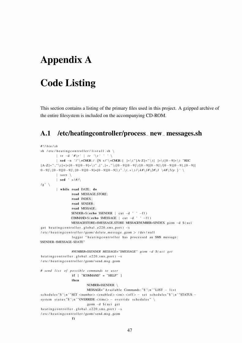
Appendix A
Code Listing
This section contains a listing of the primary files used in this project. A gzipped archive ofthe entire filesystem is included on the accompanying CD-ROM.
A.1 /etc/heatingcontroller/process new messages.sh
# ! / b i n / shsh / e t c / h e a t i n g c o n t r o l l e r / l i s t a l l . sh \
| t r −d ’ #\r ’ | t r ’\ t ’ ’ ’ \| sed −n ’ / ˆ\+CMGR: / {N s / ˆ\+CMGR: [ ] *\ ( ” [A−Z]* ” \ ) [ ]*\ ( [0 −9]*\ ) ”REC
[A−Z]* ” , ” \ ( [+]*[0 −9] [0 −9]*\ ) ” , [ ˆ , ] * , ” \ ( [0 −9][0 −9]\ / [0 −9][0 −9]\ / [0 −9][0 −9] , [0 −9][0 −9]\ : [0 −9][0 −9]\ : [0 −9][0 −9]+[0 −9][0 −9]\) ” . \ ( . * \ ) /\4 #\1#\2#\3 \4#\5/ p } ’ \
| s o r t \| sed ’ s / # /\
/ g ’ \| whi le read DATE; do
read MESSAGE STORE ;read INDEX ;read SENDER;read MESSAGE;SENDER=$ ( echo $SENDER | c u t −d ’ ’ −f1 )COMMAND=$ ( echo $MESSAGE | c u t −d ’ ’ −f1 )MESSAGESTORE=$MESSAGE STORE MESSAGENUMBER=$INDEX gcom −d $ ( u c i
g e t h e a t i n g c o n t r o l l e r . g l o b a l . e 2 2 0 s m s p o r t ) −s/ e t c / h e a t i n g c o n t r o l l e r / gcom / d e l e t e m e s s a g e . gcom > / dev / n u l l
l o g g e r ” h e a t i n g c o n t r o l l e r has p r o c e s s e d an SMS message :$SENDER−$MESSAGE−$DATE”
#NUMBER=$SENDER MESSAGE=”$MESSAGE” gcom −d $ ( u c i g e th e a t i n g c o n t r o l l e r . g l o b a l . e 2 2 0 s m s p o r t ) −s/ e t c / h e a t i n g c o n t r o l l e r / gcom / send msg . gcom
# send l i s t o f p o s s i b l e commands t o u s e ri f [ ”$COMMAND” = ”HELP” ]then
NUMBER=$SENDER \MESSAGE=” A v a i l a b l e Commands : ”$ ’\n ’ ” LIST − l i s t
s c h e d u l e s ”$ ’\n ’ ”SET <number> <enab led> <on> <o f f> − s e t s c h e d u l e s ”$ ’\n ’ ”STATUS −sys tem s t a t u s ”$ ’\n ’ ”OVERRIDE <t ime> − o v e r r i d e s c h e d u l e s ” \
gcom −d $ ( u c i g e th e a t i n g c o n t r o l l e r . g l o b a l . e 2 2 0 s m s p o r t ) −s/ e t c / h e a t i n g c o n t r o l l e r / gcom / send msg . gcom
f i
47
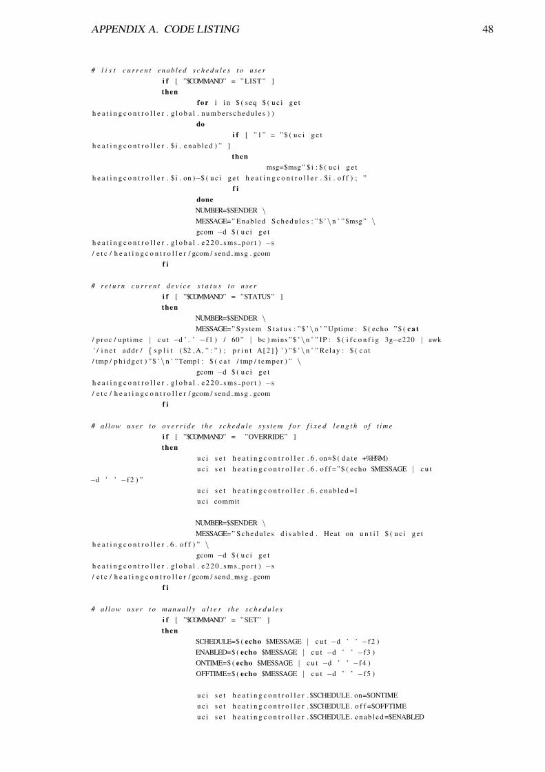
APPENDIX A. CODE LISTING 48
# l i s t c u r r e n t e n a b l e d s c h e d u l e s t o u s e ri f [ ”$COMMAND” = ” LIST ” ]then
f o r i i n $ ( seq $ ( u c i g e th e a t i n g c o n t r o l l e r . g l o b a l . n u m b e r s c h e d u l e s ) )
doi f [ ” 1 ” = ” $ ( u c i g e t
h e a t i n g c o n t r o l l e r . $ i . e n a b l e d ) ” ]then
msg=$msg” $ i : $ ( u c i g e th e a t i n g c o n t r o l l e r . $ i . on )−$ ( u c i g e t h e a t i n g c o n t r o l l e r . $ i . o f f ) ; ”
f idoneNUMBER=$SENDER \MESSAGE=” Enabled S c h e d u l e s : ”$ ’\n ’ ”$msg” \gcom −d $ ( u c i g e t
h e a t i n g c o n t r o l l e r . g l o b a l . e 2 2 0 s m s p o r t ) −s/ e t c / h e a t i n g c o n t r o l l e r / gcom / send msg . gcom
f i
# r e t u r n c u r r e n t d e v i c e s t a t u s t o u s e ri f [ ”$COMMAND” = ”STATUS” ]then
NUMBER=$SENDER \MESSAGE=” System S t a t u s : ”$ ’\n ’ ” Uptime : $ ( echo ” $ ( c a t
/ p roc / up t ime | c u t −d ’ . ’ −f1 ) / 60 ” | bc ) mins ”$ ’\n ’ ” IP : $ ( i f c o n f i g 3g−e220 | awk’ / i n e t add r / { s p l i t ( $2 , A, ” : ” ) ; p r i n t A[ 2 ]} ’ ) ”$ ’\n ’ ” Relay : $ ( c a t/ tmp / p h i d g e t ) ”$ ’\n ’ ”Temp1 : $ ( c a t / tmp / t emper ) ” \
gcom −d $ ( u c i g e th e a t i n g c o n t r o l l e r . g l o b a l . e 2 2 0 s m s p o r t ) −s/ e t c / h e a t i n g c o n t r o l l e r / gcom / send msg . gcom
f i
# a l l o w u s e r t o o v e r r i d e t h e s c h e d u l e s y s t e m f o r f i x e d l e n g t h o f t i m ei f [ ”$COMMAND” = ”OVERRIDE” ]then
u c i s e t h e a t i n g c o n t r o l l e r . 6 . on=$ ( d a t e +%H%M)u c i s e t h e a t i n g c o n t r o l l e r . 6 . o f f =” $ ( echo $MESSAGE | c u t
−d ’ ’ −f2 ) ”u c i s e t h e a t i n g c o n t r o l l e r . 6 . e n a b l e d =1u c i commit
NUMBER=$SENDER \MESSAGE=” S c h e d u l e s d i s a b l e d . Heat on u n t i l $ ( u c i g e t
h e a t i n g c o n t r o l l e r . 6 . o f f ) ” \gcom −d $ ( u c i g e t
h e a t i n g c o n t r o l l e r . g l o b a l . e 2 2 0 s m s p o r t ) −s/ e t c / h e a t i n g c o n t r o l l e r / gcom / send msg . gcom
f i
# a l l o w u s e r t o manua l l y a l t e r t h e s c h e d u l e si f [ ”$COMMAND” = ”SET” ]then
SCHEDULE=$ ( echo $MESSAGE | c u t −d ’ ’ −f2 )ENABLED=$ ( echo $MESSAGE | c u t −d ’ ’ −f3 )ONTIME=$ ( echo $MESSAGE | c u t −d ’ ’ −f4 )OFFTIME=$ ( echo $MESSAGE | c u t −d ’ ’ −f5 )
u c i s e t h e a t i n g c o n t r o l l e r . $SCHEDULE . on=$ONTIMEu c i s e t h e a t i n g c o n t r o l l e r . $SCHEDULE . o f f =$OFFTIMEu c i s e t h e a t i n g c o n t r o l l e r . $SCHEDULE . e n a b l e d =$ENABLED

APPENDIX A. CODE LISTING 49
u c i commit
NUMBER=$SENDER \MESSAGE=” S c h e d u l e $SCHEDULE u p d a t e d . ”$ ’\n ’ ” Enab led :
$ ( u c i g e t h e a t i n g c o n t r o l l e r . $SCHEDULE . e n a b l e d ) ”$ ’\n ’ ”On : $ ( u c i g e th e a t i n g c o n t r o l l e r . $SCHEDULE . on ) ”$ ’\n ’ ” Off : $ ( u c i g e th e a t i n g c o n t r o l l e r . $SCHEDULE . o f f ) ”$ ’\n ’ ” Relay : $ ( u c i g e th e a t i n g c o n t r o l l e r . $SCHEDULE . r e l a y ) ” \
gcom −d $ ( u c i g e th e a t i n g c o n t r o l l e r . g l o b a l . e 2 2 0 s m s p o r t ) −s/ e t c / h e a t i n g c o n t r o l l e r / gcom / send msg . gcom
f idone

APPENDIX A. CODE LISTING 50
A.2 /etc/heatingcontroller/schedule.sh
# ! / b i n / sh
d a t e =$ ( d a t e +%s )
ACTIVATED=0ACTIVATEDSCHEDULE=0
# c y c l e t h r o u g h u c i c o n f i g f i l e , l o c a t e e n a b l e d s c h e d u l e sf o r i i n $ ( seq $ ( u c i g e t h e a t i n g c o n t r o l l e r . g l o b a l . n u m b e r s c h e d u l e s ) )do
i f [ ” 1 ” = ” $ ( u c i g e t h e a t i n g c o n t r o l l e r . $ i . e n a b l e d ) ” ]then
# echo ENABLED: $ is l e e p 1LCDOUTPUT=$LCDOUTPUT’ S ’ $i ’ : ’ $ ( / s b i n / u c i g e t
h e a t i n g c o n t r o l l e r . $ i . on )LCDOUTPUT=$LCDOUTPUT’− ’$ ( / s b i n / u c i g e t
h e a t i n g c o n t r o l l e r . $ i . o f f ) ’ , ’
i f [ ” 1 ” = $ ( echo ” $ ( c a t / tmp / temper ) < $ ( u c i g e th e a t i n g c o n t r o l l e r . g l o b a l . s e t p o i n t ) ” | bc ) ]
theni f [ $ d a t e −ge $ ( d a t e +%s −d $ ( echo ” $ ( d a t e +%s −d $ ( u c i
g e t h e a t i n g c o n t r o l l e r . $ i . on ) ) −(($ ( u c i g e th e a t i n g c o n t r o l l e r . g l o b a l . s e t p o i n t )−$ ( c a t / tmp / temper ) ) *$ ( u c i g e th e a t i n g c o n t r o l l e r . g l o b a l . t h e r m a l c o n s t a n t ) ) ) ” | bc ) ]
theni f [ $ d a t e − l e $ ( echo ” $ ( d a t e +%s −d $ ( u c i g e t
h e a t i n g c o n t r o l l e r . $ i . o f f ) ) −(($ ( u c i g e t h e a t i n g c o n t r o l l e r . g l o b a l . s e t p o i n t )−$ ( c a t/ tmp / temper ) ) *$ ( u c i g e t h e a t i n g c o n t r o l l e r . g l o b a l . t h e r m a l c o n s t a n t ) ) ) ” | bc ) ]
thenACTIVATED=1ACTIVATEDSCHEDULE= $ i
f if i
f if i
done
s l e e p 1# s t o r e l i s t o f a c t i v a t e d s c h e d u l e s f o r use w i t h LCDecho $LCDOUTPUT > / tmp / l c d s c h e d u l e
# d i s a b l e o v e r r i d e s c h e d u l e when e x p i r e di f [ ” 6 ” −ne ”$ACTIVATEDSCHEDULE” ]then
u c i s e t h e a t i n g c o n t r o l l e r . 6 . e n a b l e d =0f i
# s e t r e l a y a c c o r d i n g t o a c t i v a t e d s c h e d u l ei f [ ” 1 ” = ”$ACTIVATED” ]then
p h i d g e t 0 0 4 $ ( u c i g e t h e a t i n g c o n t r o l l e r . $ACTIVATEDSCHEDULE . r e l a y )
i f [ ” 0 ” = $ ( echo ” $ ( c a t / tmp / temper ) < $ ( temper ) ” | bc ) ]then
# h e a t i n g a c t i v a t e d b u t t e m p e r a t u r e has f a l l e n . i n d i c a t e s problemwi th b u r n e r .
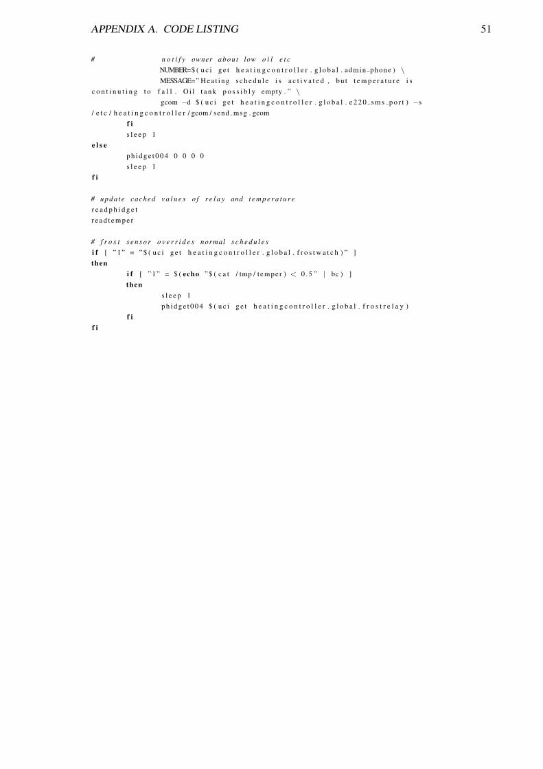
APPENDIX A. CODE LISTING 51
# n o t i f y owner abou t low o i l e t cNUMBER=$ ( u c i g e t h e a t i n g c o n t r o l l e r . g l o b a l . admin phone ) \MESSAGE=” H e a t i n g s c h e d u l e i s a c t i v a t e d , b u t t e m p e r a t u r e i s
c o n t i n u t i n g t o f a l l . O i l t a n k p o s s i b l y empty . ” \gcom −d $ ( u c i g e t h e a t i n g c o n t r o l l e r . g l o b a l . e 2 2 0 s m s p o r t ) −s
/ e t c / h e a t i n g c o n t r o l l e r / gcom / send msg . gcomf is l e e p 1
e l s ep h i d g e t 0 0 4 0 0 0 0s l e e p 1
f i
# u pd a t e cached v a l u e s o f r e l a y and t e m p e r a t u r er e a d p h i d g e tr e a d t e m p e r
# f r o s t s e n s o r o v e r r i d e s normal s c h e d u l e si f [ ” 1 ” = ” $ ( u c i g e t h e a t i n g c o n t r o l l e r . g l o b a l . f r o s t w a t c h ) ” ]then
i f [ ” 1 ” = $ ( echo ” $ ( c a t / tmp / temper ) < 0 . 5 ” | bc ) ]then
s l e e p 1p h i d g e t 0 0 4 $ ( u c i g e t h e a t i n g c o n t r o l l e r . g l o b a l . f r o s t r e l a y )
f if i

APPENDIX A. CODE LISTING 52
A.3 /etc/config/heatingcontroller
c o n f i g ’ conf ig ’ ’ g l o b a l ’op t ion ’ e 2 2 0 p p p p o r t ’ ’ / dev / ttyUSB1 ’op t ion ’ e 2 2 0 s m s p o r t ’ ’ / dev / ttyUSB2 ’op t ion ’ admin phone ’ ’+353861234567 ’op t ion ’ number schedu le s ’ ’6 ’op t ion ’ f r o s t w a t c h ’ ’1 ’op t ion ’ f r o s t r e l a y ’ ’1 0 0 0 ’op t ion ’ s e t p o i n t ’ ’ 3 0 . 0 0 ’
c o n f i g ’ s c h e d u l e ’ ’1 ’op t ion ’ on ’ ’1200 ’op t ion ’ o f f ’ ’1300 ’op t ion ’ enab led ’ ’0 ’op t ion ’ r e l a y ’ ’1 1 x x ’
c o n f i g ’ s c h e d u l e ’ ’2 ’op t ion ’ enab led ’ ’1 ’op t ion ’ r e l a y ’ ’1 1 1 1 ’op t ion ’ on ’ ’0300 ’op t ion ’ o f f ’ ’0400 ’
c o n f i g ’ s c h e d u l e ’ ’3 ’op t ion ’ enab led ’ ’1 ’op t ion ’ on ’ ’0217 ’op t ion ’ o f f ’ ’0230 ’op t ion ’ r e l a y ’ ’1 x x x ’
c o n f i g ’ s c h e d u l e ’ ’4 ’op t ion ’ enab led ’ ’1 ’op t ion ’ on ’ ’0145 ’op t ion ’ o f f ’ ’0155 ’op t ion ’ r e l a y ’ ’1 x x x ’
c o n f i g ’ s c h e d u l e ’ ’5 ’op t ion ’ o f f ’ ’0500 ’op t ion ’ on ’ ’0300 ’op t ion ’ r e l a y ’ ’1 x x x ’op t ion ’ enab led ’ ’0 ’
c o n f i g ’ s c h e d u l e ’ ’6 ’op t ion ’ r e l a y ’ ’1 x x x ’op t ion ’ on ’ ’1445 ’op t ion ’ o f f ’ ’1452 ’op t ion ’ enab led ’ ’0 ’