An Efficient Fault Locating Technique with Backup ... http:/ · measurement technology. ... which...
25
International Journal on Electrical Engineering and Informatics - Volume 9, Number 1, March 2017 An Efficient Fault Locating Technique with Backup Protection Scheme Using Wide Area Measurement for Power System with Simultaneous Faults Saptarshi ROY 1 , P Suresh BABU 2 , N V Phanendra BABU 3 , and Abhishek KUMAR 4 1,3 Research Scholar, Dept., of Electrical Engineering, NIT Warangal, INDIA 2 Assistant Professor, Dept., of Electrical Engineering, NIT Warangal, INDIA 4 M.Tech Student, Dept., of Electrical Engineering, NIT Warangal, INDIA [email protected] 1 , [email protected] 3 [email protected] [email protected] Abstract: This paper presents a synchronized phasor measurement-based wide-area backup protection scheme which uses the magnitude of sequence voltages of buses at a system protection centre to identify the faulted bus closest to the fault and faulted line. The technique is tested for various faults including simultaneous faults in various systems with interconnections. The scheme is found to be accurate and fast with today’s synchronized measurement technology. Analysis using simultaneous faults is a novel contribution in this paper. It is expected that this scheme will reduce the number of disastrous blackouts and improve the reliability and security of the power system. The required information is able to distinguish between balanced and unbalanced fault in the system. The study of new back up protection scheme is done on a WSCC-3 machine-9 bus system and an IEEE 14 bus test system. The data is simulated through EMTDC/PSCAD and MATLAB /SIMULINK softwares. Index Terms: Simultaneous Faults, Faulted bus Identification, Backup protection, faulted Line identification, Sequence Components. Nomenclature 1 1 1 , s s - Phase angle between positive sequence current and Voltage before and after series capacitor. 1 2 2 , s s - Phase angle between negative sequence current and Voltage before and after series capacitor. R 1 - Phase angle between positive- Sequence current and voltage at the other end of the protected line. R 2 - Phase angle between negative- Sequence current and voltage at the other end of the protected line s g 1 = s 1 cos 1 1s g = 1 1 cos s R g 1 = R 1 cos s g 2 = s 2 cos 1 2s g = 1 2 cos s R g 2 = R 2 cos 1. Introduction In modern societies, power systems are wide spread and electric grids are more interconnected, and transmission lines are utilized close to their limits. Hence, the traditional backup protection systems can misoperate when the power system is under stress. Like the incident of the undesired operation of the third zone of distance relays can lead to cascading failure and even major power system blackouts. Therefore, there is a growing need for novel backup protection schemes to improve power system security and reliability. Conventional backup protection schemes for the power system uses local measurements which find difficulty in distinguishing the fault from heavy loading conditions [1]. Received: May 21 st , 2016. Accepted: March 20 th , 20147 DOI: 10.15676/ijeei.2017.9.1.7 100
Transcript of An Efficient Fault Locating Technique with Backup ... http:/ · measurement technology. ... which...

International Journal on Electrical Engineering and Informatics - Volume 9, Number 1, March 2017
An Efficient Fault Locating Technique with Backup Protection Scheme Using
Wide Area Measurement for Power System with Simultaneous Faults
Saptarshi ROY1, P Suresh BABU
2, N V Phanendra BABU
3, and Abhishek KUMAR
4
1,3Research Scholar, Dept., of Electrical Engineering,
NIT Warangal, INDIA
2 Assistant Professor, Dept., of Electrical Engineering,
NIT Warangal, INDIA
4M.Tech Student, Dept., of Electrical Engineering,
NIT Warangal, INDIA
[email protected], [email protected]
Abstract: This paper presents a synchronized phasor measurement-based wide-area backup
protection scheme which uses the magnitude of sequence voltages of buses at a system
protection centre to identify the faulted bus closest to the fault and faulted line. The technique
is tested for various faults including simultaneous faults in various systems with
interconnections. The scheme is found to be accurate and fast with today’s synchronized
measurement technology. Analysis using simultaneous faults is a novel contribution in this
paper. It is expected that this scheme will reduce the number of disastrous blackouts and
improve the reliability and security of the power system. The required information is able to
distinguish between balanced and unbalanced fault in the system. The study of new back up
protection scheme is done on a WSCC-3 machine-9 bus system and an IEEE 14 bus test
system. The data is simulated through EMTDC/PSCAD and MATLAB /SIMULINK
softwares.
Index Terms: Simultaneous Faults, Faulted bus Identification, Backup protection, faulted Line
identification, Sequence Components.
Nomenclature 1
11 , ss - Phase angle between positive sequence current and Voltage before and after series
capacitor. 1
22 , ss - Phase angle between negative sequence current and Voltage before and after
series capacitor.
R1 - Phase angle between positive- Sequence current and voltage at the other end of the
protected line.
R2 - Phase angle between negative- Sequence current and voltage at the other end of the
protected line
sg1 = s1cos 1
1sg = 1
1cos s Rg1 = R1cos
sg2 = s2cos 1
2sg = 1
2cos s Rg2 = R2cos
1. Introduction
In modern societies, power systems are wide spread and electric grids are more
interconnected, and transmission lines are utilized close to their limits. Hence, the traditional
backup protection systems can misoperate when the power system is under stress. Like the
incident of the undesired operation of the third zone of distance relays can lead to cascading
failure and even major power system blackouts. Therefore, there is a growing need for novel
backup protection schemes to improve power system security and reliability.
Conventional backup protection schemes for the power system uses local measurements
which find difficulty in distinguishing the fault from heavy loading conditions [1].
Received: May 21st, 2016. Accepted: March 20
th, 20147
DOI: 10.15676/ijeei.2017.9.1.7
100

Maloperation of back up protection during stressed conditions causes the cascaded tripping.
Wide area interconnection leads to huge number of blackouts throughout the world. Recent
advancement in technology draws significant attention for the utilization of the PMU-based
wide-area measurement system (WAM) for power system protection [2], [3]. Emergence of
new technologies like smart electric grid increased the safety and reliability power networks
and mitigates the more serious consequences like blackouts.
The wide-area backup protection (WABP) based on faulted line identification (FLI) is an
interesting topic of research in recent days. This technique overcomes the limitations of
conventional backup protection and allows faster remedial action since it does not need
coordination among different zones. Various WABP schemes for FLI are reported [4]–[8]. In
[4], a WABP is proposed that compares the positive-sequence voltage magnitude at each bus
during the fault to identify the bus closest to the fault. Positive-sequence current angles of all
lines connecting the selected bus are used to identify the faulted line. The residual vector of a
synchrophasor-based state estimator, used in a supervisory system, is proposed in [5] to
improve security of an existing remote backup protection scheme. A supervisory and an agent-
based ad-hoc backup relay protection scheme based on a network infrastructure and
communication are proposed in [6].
A WABP based on the fault steady-state component of voltages and currents is proposed
for FLI in [7]. In the method, subsets of buses, called protection correlation regions (PCRs), are
formed on the basis of network topology and PMU placement. The steady-state component of
differential currents in each PCR is used to identify the PCR with the fault. A WABP algorithm
based on the fault component voltage distribution is proposed in[8]. In this scheme, the fault
component of voltage at one terminal of the line is estimated by utilizing the measured values
of fault component voltage and current at other terminals, and the faulted line is identified
based on the ratio of estimated values to measured values. A faulted area detection technique is
also used to accelerate the line identification task. The integration of a series capacitor and its
overvoltage protective device (metal–oxide varistor (MOV) and/or air gap) into the line
introduces problems to distance relaying based transmission-line protection. Typical problems
associated with relays have been addressed in [9]–[10] which include such phenomena as
voltage/current inversion, sub harmonic oscillations, and additional transients caused by the
air-gap operation. Performances of available WABP schemes [4]–[8] have not been evaluated
for series-compensated lines and may find limitation for such lines. The problems of traditional
backup protection relays can be overcome by using novel backup protection schemes, which
uses phasor measurements obtained from WAMS.
This paper proposes a WABP scheme that utilizes angle information between voltage and
current at both ends of a line for FLI. The scheme is accurate for the compensated and
uncompensated line as evident from the evaluation for a 400-kV, 9-bus system and 138KV
IEEE 14bus system with simultaneous faults also. The main contribution of this paper is the
analysis using simultaneous faults. Previously many researcher has worked with backup
protection schemes but here the analysis is done using simultaneous faults in different buses
and simultaneous faults at different lengths of same line, which is totally a new idea
introduced here.
2. Phasors of Nominal Frequency Signals with Wide Area Synchrophasor System
Consider a constant input signal x(t) ,with nominal frequency f0 [5].The phasor estimation
at nominal frequency of the signal is estimated as follows:
)02cos()( tfmXtX
The N data samples of this input Xn :{n=0,1,2,.…,N-1}are
)cos( nmXnX
)cos(1
0
21
nnX
N
nN
ncX
Saptarshi ROY, et al.
101

)cos().cos(2
1
0
nnXN
m
N
n
)]2sin(.sin2
1cos.[cos
2 21
0
nnXN
N
n
m
= cos2
mX (1)
Similarly , )sin(2
1
0
1 nXN
X n
N
n
ns
sin2
mX (2)
The Phasor 111 ns
nC
N jXXX
= ]sin[cos2
jX m
= jm eX
2
A synchrophasor system composed of Phasor measurement unit (PMU), phasor data
concentrator (PDC), GPS satellite system, super PDC. The PMU collects the real time data
from the various remote areas and send over it to local data concentrator called phasor data
concentrator via communication system. This system serves as the backup protection system
for WAPS and it is capable of acting as the substitution of conventional backup protection in
power system[11,12]. The relay takes the decision is based on collected data through
communication network. The suggested technique increases the reliability and stability of the
system. PMU measures positive sequence voltage magnitude and current phase angle of a
power system in real time with synchronised time stamped data[12]. The synchronization is
done by sampling of voltage and current waveforms using timing signals from different
common time reference frame, such as the Global Positioning System (GPS) Satellite or any
other reference timing signal generator.
A. Calculation of Protection criterion values
Assume a voltage or current having orthogonal components X1c and X1s [ 12,19]..
Signal sc jXXnX 111 )( (3a)
21
21
21
*11 )(*)( scm XXXnXnX (3b)
)( 21
211 scm XXX (3c)
B. Calculation of Power
Suppose Voltage signal is denoted by scn jUUU 111 (3d)
Current Signal is denoted by scn jiii 111
So, Power nn ixUS
11 (3e)
)()( 1111 scsc jiixjUU
)()( 11111111 sccssscc ixUixUjixUixU (3f)
Active Power )(5.0 1111 sscC ixUixUP (3g)
Reactive Power )*(5.0 1111 sccS iUixUQ (3h)
An Efficient Fault Locating Technique with Backup Protection
102

3. Proposed Method
The proposed technique is useful for monitoring of large power networks like generating
plants, large transmission lines and significant control points. Synchrophasor using phasor
measurement unit provides all significant state measurement required for the operation
including voltage magnitude, voltage phase angle and frequency.The rate of data sampling is
maintained at 4 kHz. The Proposed Technique is follows:
Algorithm:
Step 1: Start
Step 2: Collect all data from all PMUs and PDCs in real time.
Step 3: Obtain minimum Positive sequence voltage magnitude or maximum negative or zero
sequence magnitude.(vk)
Step 4: Compare with the threshold value. If it is less than minimum positive sequence voltage
magnitude or more than maximum negative or zero sequence magnitude value, then there is no
fault in the system.
Otherwise, area or bus k is the nearest to the fault .
go to Step 5 and Proceed:
Step 5: Check whether it is a balanced fault or unbalanced fault.
The negative- and zero-sequence voltages are utilized to identify unbalanced faults [13]. For
these faults, the pickup criterion is defined as
nmnm VKVVKV 0022 (4)
Where Vm2 & Vm0 are the negative and Zero sequence components of the waveform of
mth
bus and Vn is the rated voltage of the bus. K2 and K0 are the constants. In this paper, the
thresholds of K2 and K0 and set at 0.1 for an unbalanced fault. The reason of choosing low
threshold settings are that the combined information of negative and zero-sequence voltage
magnitudes could improve the sensitivity of pickup criterion during a high-resistance earth
fault[13].
If unbalanced fault condition is not satisfied then the substation will check for balanced
fault criterion:
nm VKV 11 (5)
Vm1 is the positive sequence voltage of mth
bus. K1 is a constant whose value is kept 0.6 in
this paper. Higher threshold for the balanced fault is chosen in order to avoid frequent pickup
of the WABP system under normal switching condition of the power system. If it is as high as
0.8 or 0.9 then even any load fluctuation also can generate trip signal and if it is as low as 0.1
or 0.2 also then in case of many faults, trip signal may not be generated[13]. So, a moderate
value 0.6 is chosen.
Step 6: Compute absolute angle difference of all lines connected to bus or area k.
Step 7: Obtain highest value line of Phase angle.
Step 8: The jth
line connected to area k is faulted line.
Step 9: Authentication if series capacitor compensation involved in the faulted line:
Check 0,, 2
1
22 allggg Rss (6)
for an unbalanced fault.
Check 0,, 1
1
11 allggg Rss (7)
for a balanced fault.
Step 10: Relaying Algorithm
Step 11: Stop
Saptarshi ROY, et al.
103
4. Case Studies
A. Wscc-3 Machine-9 Bus System Applications
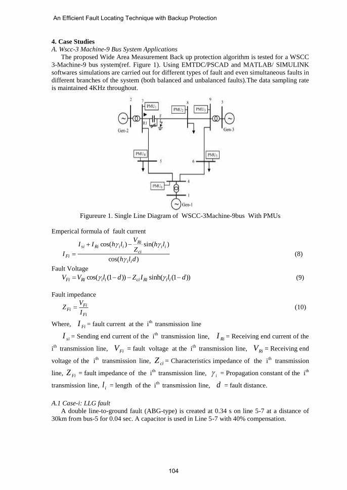
The proposed Wide Area Measurement Back up protection algorithm is tested for a WSCC
3-Machine-9 bus system(ref. Figure 1). Using EMTDC/PSCAD and MATLAB/ SIMULINK
softwares simulations are carried out for different types of fault and even simultaneous faults in
different branches of the system (both balanced and unbalanced faults).The data sampling rate
is maintained 4KHz throughout.
Figureure 1. Single Line Diagram of WSCC-3Machine-9bus With PMUs
Emperical formula of fault current
)cos(
)sin()cos(
dlh
lhZ
VlhII
Iii
iici
RiiiRisi
Fi
(8)
Fault Voltage
))1(sinh())1(cos( dlIZdlVV iiRiciiiRiFi (9)
Fault impedance
Fi
FiFi
I
VZ (10)
Where, FiI = fault current at the ith
transmission line
siI = Sending end current of the ith
transmission line, RiI = Receiving end current of the
ith
transmission line, FiV = fault voltage at the i
th transmission
line, RiV = Receiving end
voltage of the ith
transmission line, ciZ = Characteristics impedance of the i
th transmission
line, FiZ = fault impedance of the ith
transmission line, i = Propagation constant of the i
th
transmission line, il = length of the i
th transmission
line, d = fault distance.
A.1 Case-i: LLG fault
A double line-to-ground fault (ABG-type) is created at 0.34 s on line 5-7 at a distance of
30km from bus-5 for 0.04 sec. A capacitor is used in Line 5-7 with 40% compensation.
An Efficient Fault Locating Technique with Backup Protection
104

(a)
(b)
(c)
(d)
Saptarshi ROY, et al.
105

(e)
(f)
(g)
Figure 2(a). Zero Sequence Voltage Profile at bus 7 (b). Negative Sequence Voltage Profile at bus 5
(c). Zero Sequence Voltage Profile at bus 5 (d). Zero Sequence Voltage Profile at bus 4
(e). Zero Sequence Voltage Profile at bus 9 (f). Zero Sequence Voltage Profile at bus 8
The observation of the Figure no. 2(a), (b), (c), (d), (e), (f), (g) clearly shows it satisfies
equation 4, the pickup condition for unbalanced fault as:
KVVKVK nn 4002
Bus 5 zero sequence voltage profile having maximum voltage magnitude among other
buses in the network. However depending on source ,load and measurement errors in each
substation some samples may deviate from the pickup criteria. So, the bus 5 data satisfies the
An Efficient Fault Locating Technique with Backup Protection
106

criterion for an unbalanced fault and as bus 5 having maximum zero sequence magnitude, Bus5
is closest to the fault. All the voltages are expressed in KV.
(a)
(b)
Figure 3(a) Phase variation of line 5-7 (b). Phase variation of line 4-5
Two lines are adjacent to bus 5, line 5-7 and line 4-5. The phase variations of those lines
are shown in Figure 3( a) and Figure 3(b). The variations are expressed in radians. It is seen
that the variations of the phase lies between - 𝜋/2 to + 𝜋/2 ( -90degree to + 90 degree ).
(a)
Saptarshi ROY, et al.
107

(b)
(c)
Figure 4(a) g2s profile (b). g2s profile (c). g2R profile
From the Figure 3(a),3(b) and 4(a),4(b),4(c) it is clear that line 5-7 is satisfying equation
(6) also, hence the criterion and authentication of an unbalanced fault. So, line 5-7 is the
faulted line.
A.2 Case-ii :LLLG Fault
a LLLG fault is created at 0.34 s on line 5-7 at a distance of 30km from bus-5 for 0.04
sec. After collecting all data, the following analysis has been done
(a).
An Efficient Fault Locating Technique with Backup Protection
108

(b).
(c).
(d).
(e).
Saptarshi ROY, et al.
109

(f)
(g).
(h).
Figure 5(a) Zero Sequence Voltage Profile at bus 5 (b).Negative Sequence Voltage Profile at bus 5
(c). Positive Sequence Voltage Profile at bus 5 (d). Positive Sequence Voltage Profile at bus 7
(e) Positive Sequence Voltage Profile at bus 4 (f) Positive Sequence Voltage Profile at bus 6
(g) Positive Sequence Voltage Profile at bus 9 (h) Positive Sequence Voltage Profile at bus 8
All the units of voltage are expressed in KV here. Time is expressed in second. The
observation of the Figure 5(a) to 5(h) clearly shows it does not satisfy equation (4), the pickup
condition for unbalanced fault as nm VKV 22 && nm VKV 00
KVVKVK nn 4002
But it satisfies equation (5), the pickup criterion of a balanced fault as KVVK n 2401
And minimum value of positive sequence voltage exist in bus 5. So, bus 5 is considered as
bus nearest to the fault.
An Efficient Fault Locating Technique with Backup Protection
110

(a).
(b).
(c).
Figure 6(a). Phase Variation Line 5-7
(b). Phase Variation Line 4-5
(c). Variation of, Ø1s for Line 5-7
Saptarshi ROY, et al.
111

(a).
(b).
(c).
Figure 7(a). g1s profile during LLLG fault
(b). g1s’ profile during LLLG fault
(c). g1R profile during LLLG fault
From the Figure 6(a), 6(b), 6(c) and 7(a), 7(b),7(c), it is clear that line 5-7 is satisfying
equation (7), hence the criterion and authentication of an balanced fault. So, line 5-7 is the
faulted line.
An Efficient Fault Locating Technique with Backup Protection
112

Figure 8. Positive Sequence Impedance Trajectory in Z-ø plane
The positive sequence impedance seen by the relay during the fault is plotted in the
impedance plane(ref. Figure8). From the trajectory of the fault impedance, it can be concluded
which zone the locus is confined and whether distance relay is going to generate any trip signal
to circuit breaker or not and if there is any chance for evolving load encroachment problem or
not.
A.3 Case-iii: Simultaneous Faults
Protection of power systems or occurrence of faults in a power network is not an isolated
task [14,15,16]. It may happen simultaneously. So, now the new WABP algorithm is tested
under the condition of occurrence of simultaneous faults across the power network. And here
also it is found that it is having immunity to support simultaneous occurrence of faults
phenomena.
- Bus 5 With LLL and Bus 9 with LLG Fault
(a).
(b).
Figure 9 (a) Negative Sequence Profile at bus 9 (b). Zero Sequence Profile at bus 9
Saptarshi ROY, et al.
113

Here also both the sequence voltage profiles will satisfy their individual fault pick up
criterion (ref. Figure 9(a) and Figure 9(b)). However depending on source, load and
measurement errors in each substation some samples may deviate from the pickup criteria.
- Bus 5, Bus 8, Bus 9 with balanced Fault.
Figure 10 (a) and 10(b) are showing the voltage profiles at bus 5
(a).
(b).
Figure 10(a). Zero Sequence Voltage bus 5 (b). Positive Sequence Voltage bus 5
During load encroachment and power swing conditions, the positive sequence impedance
may enters zone3 of relay which can cause undesired tripping of lines. But in those cases FLI
criterion will not satisfy and thus such events will declare as a non-fault situation by the
scheme. Thus WABP Scheme mitigates the problem raised during load encroachment and
power swing conditions. So, this scheme is useful for Zone 3 protection support also.
A.4 Case-iv: Sources of error/ Limitation: Simultaneous faults at different Lengths of the
same Line :
A-G fault is created at Line 5-7 at 0.32 sec for 0.04 sec at 30KM distance from bus 5 and at
the same time another fault is created on the same line and almost at the same distance (within
1km)for 0.34 sec for 0.04 sec which is a 3-phase fault. Now the fault voltage profile from 0.32
sec to 0.38 sec for bus 5 is indicated as follows:
An Efficient Fault Locating Technique with Backup Protection
114

(a).
(b).
(c).
Figure 11(a) Negative Seq. voltage
(b). Zero Seq. Voltage
(c) Positive Seq. Voltage
Figure 11( a,b,c): Sequence voltage profiles at bus 5
From the above Figure no. 11(a), 11(b), 11(c) it is clear that result waveforms having two
parts.
i) Up to 0.32-0.34 sec, it is obeying the pickup criterion of an unbalanced fault.
ii) 0.34-0.38sec, the waveforms are obeying the pickup criterion for a balanced fault.
Theoretically, the wave should have three parts,0.32-0.34sec unbalanced fault,0.34-0.36 sec
both balanced and unbalance fault exist in the line and 0.36-0.38 sec balanced fault exist in the
line. Here the circuit is obeying superposition theorem of network. As 3-phase fault is the most
Saptarshi ROY, et al.
115

severe fault in the circuit, it nullifies the effect of an unbalanced fault and predominates. So,
with this scheme if some balanced fault is indicating, it may contain some percentage of
simultaneous unbalanced faults also, in the line as faults in power system is not an isolated
issue. This scheme is showing unbalanced fault means the line contains unbalanced faults only
but in case of balanced fault, the line may contain some percentage of unbalanced faults also.
So, Existence of Simultaneous faults in the same Line can be confirmed by the following logic:
i) Balanced + Unbalanced- Output Balanced
ii) Balanced + Balanced- Output Balanced
iii) Unbalanced + Balanced- Output Balanced
iv) Unbalanced + Unbalanced –Output Unbalanced
The above four postulates can be represented in a form of truth table as table 1
Table 1. Simultaneous fault logic
Balanced Unbalanced Output
Balanced
High X High
Low High Low
X Indicates don’t care condition.
With the existing scheme, it is difficult to distinguish the Simultaneous faults in a same
line. Moreover, depending on the source strength, demand of load and other errors in
measurement and operation, some samples may deviate from their own pick up criterion
sometimes[16,17,18,19].
Figure 12. Negative Sequence Profile at bus5
Figure 12 is another case study, where an A-G fault is created at 0.34 sec for 0.04 sec on
Line 5-7 at 30KM distance, at the same time another close in fault which is a 3-phase fault by
nature is created on the same line for 0.02sec.Same as previous case between 0.35-0.37 sec, the
balanced fault predominates and suppressed the effect of unbalanced A-G fault and once the
balanced fault is cleared ,between 0.37-0.38 sec, the effect of unbalanced fault is again seen.
Thus output is a composite Figure in nature. So, in the presence of a balanced fault, the effect
of unbalanced fault cannot be distinguished as LLL fault predominates with respect to its
degree of severity than LG fault.
B. Application on An IEEE-14 Bus System
The method discussed above is also tested on an IEEE-14 bus system to prove its
effectiveness. The test system (ref. Figure 13) is constructed by using PSCAD software.
Different cases are simulated on this test system to show the effectiveness of the proposed
method.
An Efficient Fault Locating Technique with Backup Protection
116

Figure 13. Single Line Diagram of an IEEE-14 bus test system
B.1 Case-i: LG fault
(a).
(b).
Saptarshi ROY, et al.
117

(c).
Figure 14(a,b,c). Sequence Voltage profiles at bus 5 and phase angle variation in line 1-5
A Phase A-G fault is created at line 1-5 at 0.5 sec for 0.05 sec duration at a distance 50Km
from bus1 (33.87 Km from bus 5). A capacitor with 40% compensation is used in line 1-5. The
bus nominal voltages are 138 KV. From the analysis of its sequence component voltages and
phase angles it is found that bus5 is satisfying the bus closest to the fault and unbalanced fault
pick up criteria as K2Vn =,K0Vn = 13.8 KV. Bus 5 is connected with line 1-5, line 4-5 and line
5-6. Among them line 1-5 has highest value of phase angle. So, line 1-5 is the faulted line. The
sequence voltages and phase angle variations are shown in Figure 14 (a,b,c). All g index values
are also found to be positive. So, it is satisfying the authentication of unbalanced fault also.
B.2 Case-ii :LLLG Fault
(a). Positive Sequence Voltage profile at bus 5
(b). Phase angle variation of line 1-5
Figure 15(a,b). Sequence Voltage profile at bus 5 and phase angle variation in line 1-5
An Efficient Fault Locating Technique with Backup Protection
118

A LLLG fault is created at line 1-5 at 0.5 sec for 0.05 sec duration at a distance 50Km
from bus1 (33.87 Km from bus 5). A capacitor with 40% compensation is used in line 1-5. The
bus nominal voltages are 138 KV. From the analysis of its sequence component voltages and
phase angles, it is found that bus5 is satisfying the bus closest to the fault and balanced fault
pick up criteria as K1Vn = 82.8 KV. Bus 5 is connected with line 1-5, line 4-5 and line 5-6.
Among the line 1-5 has highest value of phase angle. So, line 1-5 is the faulted line. The
sequence voltage and phase angle variations are shown in Figure 15(a,b). All g index values
are also found to be positive. So, it is satisfying the authentication of balanced fault also.
B.3 Case-iii: Simultaneous Faults
- Line 1-5 with LLLG fault and Line 5-4 with LG fault:
( a). Positive sequence voltage profile at line 1-5
(b). Negative sequence voltage profile at line 5-4
(c). Zero sequence voltage profile at line 5-4
Saptarshi ROY, et al.
119

(d). Phase angle variation of line 5-4
(e). Phase angle variation of line 1-5
Figure 16(a,b,c,d,e). Sequence Voltage profiles and phase angle variations
A LLLG fault is created at 50 Km distance from bus 5 at line 1-5 at 0.52 sec for 0.06 sec
duration and a LG close in fault is created at line 5-4 at 0.5 sec for 0.05sec duration. From the
sequence voltages and phase angle variation analysis, it is found that each line will satisfy their
own individual fault pick up criteria. The sequence voltage profiles and phase angle variations
are shown in Figure 16(a,b,c,d,e).
- Simultaneous faults at different Lengths of the same Line:
An AG fault is created at line 1-5 in close in distance at a time 0.5 for 0.05 sec duration and
a LLLG fault is created in the same line at a distance 20 Km from bus 1 at 0.52 sec for 0.06
sec duration. The composite fault voltage sequence waveforms are shown in Figure 17(a,b).
(a). Zero sequence voltage profile at line 1-5
An Efficient Fault Locating Technique with Backup Protection
120

(b). Negative sequence voltage profile at line 1-5
Figure 17(a,b). Sequence Voltage profiles in line 1-5 when simultaneous AG and LLLG fault
exist in the line
From the composite waveform it is clear that from 0.5-0.52 sec unbalanced fault pick up
criterion is satisfying and from 0.52-0.58 sec, balanced fault pick up criterion is gradually
predominating. The only difference with 9bus case studies is, in case of 9 bus, whenever there
exist a balanced and unbalanced fault in the system, the balanced fault starts to predominate
immediately but in case of IEEE 14 bus system balanced fault starts to predominate gradually.
The cause of this change can be explained as the influence of the length or size of the system
which introduces a delay in the predomination of balanced fault. The delay can be further
increased if the methodology is tested for more higher and larger test systems.
5. Discussions
A. Reduction of PMUS
We need voltage data of the whole system for analysis of the methodology. But placing
PMUs in each bus to capture data is a costly affair specially in case of a larger system. Here, an
Integer Linear Programming (ILP) is used to solve the PMU placement problem. The results
obtained are presented in the Table II shown below. Our objective is to make the system
complete observable with minimum number of PMUs. The minimum number of PMUs to
make the system complete observable is roughly 1/3 rd of the total number of buses exist in
the system except zero injection buses[15,20].
Table 2: Complete observability under normal operating conditions in test systems
System Location of PMUs in bus no. Number of PMUs
WSCC-3-machine-9bus 4 ,6 ,8 3
IEEE 14 bus 2,6,8,9 4
B. Stability of the method
This method will work fine even in the transient conditions of the network. It is not
depending on fault level. The method is totally depending on extracted voltage and current
samples. So, the method is stable and not going to affect the stability of the system.
6. Conclusion
A Novel WABP scheme based on synchronized phasor measurements is proposed in this
paper. The sequence components of voltage, phase angles and the sign of cosine of the angle
between voltage and current at both ends of a line is utilized to identify The faulted area and
faulted branch. Simulation results for the nine-bus and IEEE 14bus power system show that the
method performs correctly during several faults in systems, interconnected systems and
simultaneous faults. Apart from the simple setting principle, the scheme has the ability to
Saptarshi ROY, et al.
121

distinguish the fault from load encroachment and power swing and can mitigate the short
comings of the conventional backup protection scheme. It is helpful to prevent blackouts. Thus
with the context of now a today’s backup protection schemes, the scheme described here is
commendable.
APPENDIX-A
System data for 3-machine 9-bus conFigureuration:
Gererators
Gen-1: 600 MVA,22KV,50HZ Gen-2: 465 MVA,22KV,50HZ Gen-3: 310
MVA,22KV,50HZ
Transformers
T1: 600 MVA,22/400KV,50HZ,T2: 465 MVA,22/400KV,50HZ,D/Y T3: 310
MVA,22/400KV,50HZ,D/Y
Transmission line:
Length of line 7-8=320Km line 8-9=400Km line 7-5=310Km line 5-4=350Km line 6-
4=350Km line 6-9=300km.
Loads
Load A=300MW+j100MVAr. Load B=200MW+j75MVAr. Load C=150MW+j75MVAr.
Other parameter used are same as used in Reference [11] and IEEE 14 bus test system data
is obtained from Reference [21]
7. References
[1]. S.Horowitz and A. G.Phadke, “Third zone revisited”, IEEE Transactions on Power
Delivery, ,vol. 21, no. 1, pp. 23–29, Jan.2006.
[2]. J. D. Ree,V. Centeno,J. S. Thorp, and A. G. Phadke, “Synchronized phasor measurement
applications in Power systems,” IEEE Transactions on Smart Grid, vol. 1, no. 1, pp.
20–27, June 2010.
[3]. A. G. Phadke and J. S. Thorp, Synchronized Phasor Measurements and Their
Applications. New York: Springer, 2008.
[4]. M. M. Eissa, M. E. Masoud, and M.M.M. Elanwar, “A novel backup wide area
protection technique for power transmission grids using phasor measurement unit,”
IEEE Transactions on Power Delivery, vol. 25, no. 1, pp. 270–278 , Jan. 2010.
[5]. P. V. Navalkar and S. A. Soman, “Secure remote backup protection of transmission lines
using synchrophasors, ” IEEE Transactions on Power Delivery ,vol. 26, no. 1, pp. 87–96,
Jan. 2011.
[6]. H. Lin, S. Sambamoorthy, S. Shukla, J. Thorp, and L Mili, “Ad-hoc vs. supervisory wide
area backup relay protection validated on power/network co-simulation platform,”
presented at the 17th Power System Computation Conference, Stockholm, Sweden, Aug.
22–26, 2011.
[7]. J. Ma, J. Li, J. S. Thorp, A. J. Arana, Q. Yang, and A. G. Phadke, “A fault steady state
component-based wide area backup protection algorithm,” IEEE Transactions on Smart
Grid., vol. 2, no. 3, pp. 468–475, Sep.2011.
[8]. Z.He, Z. Zhang,W. Chen,O. P.Malik, and X. Yin, “Wide-area backup protection
algorithm based on fault component voltage distribution,” IEEE Transactions on Power
Delivery, vol. 26, no. 4, pp. 2752–2760, Oct. 2011.
[9]. B. Kasztenny, “Distance protection of series-compensated lines problems and solutions,”
presented at the 28th Annual Western Protection Relay Conference, Spokane, WA, USA,
Oct. 22–25, 2001.
[10]. D. Novosel, A. G. Phadke,M.M. Saha, and S. Lindahl, “Problems and solutions for
microprocessor protection of series compensated lines” , Proceedings of Conference on
Development on Power System. Protection, 1997, pp. 18–23.
An Efficient Fault Locating Technique with Backup Protection
122

[11]. P.K Nayak, A.K Pradhan, and P. Bajpai, “A Fault Detection Technique for the Series-
Compensated Line During Power Swing”, IEEE Transactions on Power Delivery, vol. 28,
no. 2, April 2013,pp.714-722.
[12]. S.N.Muneswar, R.Hasabe, D.Shelar, P.Kose, “A New Adaptive PMU based Protection
Scheme for Interconnected Transmission Network System”, International conference on
Circuit , Power and Computing Technologies, 2014.
[13]. P.K Nayak, A.K Pradhan, and P.Bajpai, “Wide-Area Measurement-Based Backup
Protection for Power Network with Series Compensation”, IEEE Transactions on Power
Delivery, vol. 29, no. 4, August 2014, pp.1970-1977.
[14]. A.K.Pradhan, P.Jena,” Directional relaying in the Presence of a thyristor-controlled series
capacitor”, PES General Meeting, IEEE, 27-31 July, 2014.
[15]. T.Routtenberg, Yao Xie, R.M.Willett, Lang Tong,” PMU Based Detection of Imbalance
in Three-Phase Power Systems ”, IEEE Transactions on Power Systems ,Vol. 30, no. 4,
July 2015,pp.1966-1976.
[16]. Ali.H.Al Mohammed, M.A.Abido, ”A Fully Adaptive PMU Based Fault Location
Algorithm for Series compensated Lines“, IEEE Transactions on Power Systems
,Vol.29, no.5, September 2014, pp.2129-2137.
[17]. I.Kamwa, S.R.Samantaray, G. Joos, ”Wide Frequency Range Adaptive Phasor and
Frequency PMU Algorithms”, IEEE Transactions on Smart Grid ,Vol. 5, no.2,
March2014, pp.569-579.
[18]. P.Kundu, A.K.Pradhan, ”Online identification of protection element failure using
wide area measurements”, IET Generation, Transmission and Distribution, 2015, Vol. 9,
Issue 2, pp 115-123.
[19]. W.Rebizant , J.Szafran and A.Wiszniewski , Digital signal processing in power system
protection and control, Springer, Poland,2011.
[20]. Emily R Fernandes et al. ,” Application of a phasor-only state estimator to a large power
system using real pmu data “, IEEE Transactions on Power System, Vol.32, No.1,
January 2017, pp.411-420.
[21]. Power flow data for IEEE 14 bus test case.
http://www.ece.ubc.ca/~hameda/download_files/case14.m
Saptarshi ROY, Received the B.E degree in Electrical Engineering from
Jadavpur University, West Bengal, India in 2009. Received M.Tech degree
from NIT Warangal in 2014. Currently he is pursuing PhD in Electrical
Engineering in the department of Electrical Engineering, National Institute of
Technology, Warangal, India. His areas of interest are power system
protection, Phasor Measurement Unit applications in power systems,
Synchrophasors applications in power systems.
Suresh Babu PERLI, Currently he is working as an Assistant Professor in
Department of Electrical Engineering, National Institute of Technology,
Warangal. His areas of interest are Power System Protection with digital
multifunction relays, Development of Adaptive protection schemes and
Digital filtering algorithms.
Saptarshi ROY, et al.
123

N V Phanendra BABU, He is currently doing Research in the Department of
Electrical Engineering, National Institute of Technology Warangal, India. His
areas of interest are Optimal PMU Placement, Wide-Area protection.
Abhishek KUMAR, He received B.E degree in Electrical Engineering from
Shree Vaishnav Institute of Technology and Science, Indore in 2014.
Currently he is pursuing M.Tech in Power Systems Engineering in the
department of Electrical Engineering, National Institute of Technology,
Warangal, India. His areas of interest are adaptive relaying, digital filtering
algorithms and fault location algorithms.
An Efficient Fault Locating Technique with Backup Protection
124