An Efficient Acceleration of Solving Heat and Mass ...
12
Computer and Information Science; Vol. 13, No. 2; 2020 ISSN 1913-8989 E-ISSN 1913-8997 Published by Canadian Center of Science and Education 75 An Efficient Acceleration of Solving Heat and Mass Transfer Equations with the Second Kind Boundary Conditions in Capillary Porous Radially Composite Cylinder Using Programmable Graphics Hardware Hira Narang 1 , Fan Wu 1 , & Abdul Rafae Mohammed 2 1 Professor, Computer Science Department, Tuskegee University, Tuskegee, Alabama, USA 2 Research Student, Computer Science Department, Tuskegee University, Tuskegee, Alabama, USA Correspondence: Hira Narang, Professor, Computer Science Department, Tuskegee University, Tuskegee, Alabama, USA. Received: August 21, 2019 Accepted: September 5, 2020 Online Published: April 29, 2020 doi:10.5539/cis.v13n2p75 URL: https://doi.org/10.5539/cis.v13n2p75 Abstract With the recent developments in computing technology, increased efforts have gone into the simulation of various scientific methods and phenomenon in engineering fields. One such case is the simulation of heat and mass transfer equations which is becoming more and more important in analyzing various scenarios in engineering applications. Analysing the heat and mass transfer phenomenon under various environmental conditions require us to simulate it. However, this process of numerical solution of heat and mass transfer equations is very time consuming. Therefore, this paper aims at utilizing one of the acceleration techniques developed in the graphics community that exploits a graphics processing unit (GPU) which is applied to the numerical solutions of heat and mass transfer equations. The nVidia Compute Unified Device Architecture (CUDA) programming model can be a good method of applying parallel computing to program the graphical processing unit. This paper shows a good improvement in the performance, while solving the heat and mass transfer equations for a capillary porous radially composite cylinder with the second kind of boundary conditions, numerically running on GPU. This heat and mass transfer simulation is implemented using CUDA platform on nVidia Quadro FX 4800 graphics card. Our experimental results depict the drastic performance improvement when GPU is used to perform heat and mass transfer simulation. GPU can significantly accelerate the performance with a maximum observed speedup of more than 8 fold times. Therefore, the GPU is a good approach to accelerate the heat and mass transfer simulation. Keywords: numerical solution, heat and mass transfer, general purpose graphics processing unit, CUDA 1. Introduction During the last 50 years, numerous researchers and specialists working in Heat and Mass Transfer studies have spent huge amount of efforts in discovering insights both experimentally and numerically. To absolutely investigate physical phenomena of heat and mass transfer, reproducing and analyzing heat and mass transfer scenarios, such as, heat conduction, convection, and radiation are essential. This simulation of heat and mass transfer can be achieved by using parallel computing technology. Initially during the ascent of computing technology, computers were used to find solutions to sequential problems but later when computers with high computational capabilities were introduced, people started using them for heat and mass transfer problems. However, these high-end computers consumed huge amount of time to simulate the intensive and complex processes of heat and mass transfer. Thus we need to accelerate this process of simulation to be able to effectively analyze and understand the complex process of heat and mass transfer. This paper uses the parallel computing capability of Graphical Processing Units to accelerate the heat and mass transfer recreation. GPUs are extremely proficient considering hypothetical floating-point task rates (Owens, 2007). Along these lines, in contrast to a super-computer, GPUs is a great co-processor on a typical PC which can be used to perform the heat and mass transfer simulations using less amount of resources. The GPU has a few focal points over CPU architectures, for example, parallel computing, calculation escalated workloads,
Transcript of An Efficient Acceleration of Solving Heat and Mass ...

Computer and Information Science; Vol. 13, No. 2; 2020
ISSN 1913-8989 E-ISSN 1913-8997
Published by Canadian Center of Science and Education
75
An Efficient Acceleration of Solving Heat and Mass Transfer
Equations with the Second Kind Boundary Conditions in Capillary
Porous Radially Composite Cylinder Using Programmable Graphics
Hardware
Hira Narang1, Fan Wu1, & Abdul Rafae Mohammed2
1 Professor, Computer Science Department, Tuskegee University, Tuskegee, Alabama, USA
2 Research Student, Computer Science Department, Tuskegee University, Tuskegee, Alabama, USA
Correspondence: Hira Narang, Professor, Computer Science Department, Tuskegee University, Tuskegee,
Alabama, USA.
Received: August 21, 2019 Accepted: September 5, 2020 Online Published: April 29, 2020
doi:10.5539/cis.v13n2p75 URL: https://doi.org/10.5539/cis.v13n2p75
Abstract
With the recent developments in computing technology, increased efforts have gone into the simulation of
various scientific methods and phenomenon in engineering fields. One such case is the simulation of heat and
mass transfer equations which is becoming more and more important in analyzing various scenarios in
engineering applications. Analysing the heat and mass transfer phenomenon under various environmental
conditions require us to simulate it. However, this process of numerical solution of heat and mass transfer
equations is very time consuming. Therefore, this paper aims at utilizing one of the acceleration techniques
developed in the graphics community that exploits a graphics processing unit (GPU) which is applied to the
numerical solutions of heat and mass transfer equations. The nVidia Compute Unified Device Architecture
(CUDA) programming model can be a good method of applying parallel computing to program the graphical
processing unit. This paper shows a good improvement in the performance, while solving the heat and mass
transfer equations for a capillary porous radially composite cylinder with the second kind of boundary conditions,
numerically running on GPU. This heat and mass transfer simulation is implemented using CUDA platform on
nVidia Quadro FX 4800 graphics card. Our experimental results depict the drastic performance improvement
when GPU is used to perform heat and mass transfer simulation. GPU can significantly accelerate the
performance with a maximum observed speedup of more than 8 fold times. Therefore, the GPU is a good
approach to accelerate the heat and mass transfer simulation.
Keywords: numerical solution, heat and mass transfer, general purpose graphics processing unit, CUDA
1. Introduction
During the last 50 years, numerous researchers and specialists working in Heat and Mass Transfer studies have
spent huge amount of efforts in discovering insights both experimentally and numerically. To absolutely
investigate physical phenomena of heat and mass transfer, reproducing and analyzing heat and mass transfer
scenarios, such as, heat conduction, convection, and radiation are essential. This simulation of heat and mass
transfer can be achieved by using parallel computing technology. Initially during the ascent of computing
technology, computers were used to find solutions to sequential problems but later when computers with high
computational capabilities were introduced, people started using them for heat and mass transfer problems.
However, these high-end computers consumed huge amount of time to simulate the intensive and complex
processes of heat and mass transfer. Thus we need to accelerate this process of simulation to be able to
effectively analyze and understand the complex process of heat and mass transfer.
This paper uses the parallel computing capability of Graphical Processing Units to accelerate the heat and mass
transfer recreation. GPUs are extremely proficient considering hypothetical floating-point task rates (Owens,
2007). Along these lines, in contrast to a super-computer, GPUs is a great co-processor on a typical PC which
can be used to perform the heat and mass transfer simulations using less amount of resources. The GPU has a
few focal points over CPU architectures, for example, parallel computing, calculation escalated workloads,
http://cis.ccsenet.org Computer and Information Science Vol. 13, No. 2; 2020
76
including higher data transfer capacity, higher floating point throughput. The GPU can be an appealing
contrasting option to groups or super-PC in high performance computing disciplines. CUDA (NVIDIA, 2009) by
nVidia effectively demonstrated its push to create both programming and memory models. CUDA is another
parallel, C-like Application Programing Interface (API), which sidesteps the rendering Interface and dodges the
challenges faced while using GPGPU. Parallel calculations are communicated as universally useful, C-like
language kernels working in parallel at all points in an application.
This paper builds up the numerical solutions for Two-point Initial-Boundary Value Problems (TIBVP) of Heat
and Mass Transfer with the second kind of boundary conditions in the capillary porous radially composite
cylinder. These issues can be found in a few applications in drying processes, space science, absorption of
supplements, transpiration cooling of space vehicles at reentry stage, and numerous other scientific and
engineering issues. Albeit some conventional methodologies of parallel processing to the arrangements of a
portion of these issues have been researched, nobody appears to have investigated the high-performance
computing for heat and mass transfer issues with reduced co-processing capacities of GPU, which incorporates
multi-processors on a chip. With the benefits of this novel innovation, we developed algorithms to solve the
TIBVP with the second kind boundary conditions and contrast with some current solutions with similar issues.
The majority of our exploratory outcomes demonstrate huge execution and performance speedups. The greatest
watched speedups are around 10 times.
The rest of the paper is organized as follow: Section II briefly introduces some closely related work; Section III
describes the basic information on GPU and CUDA; Section IV presents the mathematical model of heat and
mass transfer and numerical solutions to heat and mass transfer equations; Section V presents our experimental
results of our experiment on Composite Solid Cylinder on Second Kind Boundary Conditions; And Section VI
concludes this paper and give some possible future work directions.
2. Related Work
The simulation of heat and mass transfer has been an extremely hotly debated issue for a long time. Furthermore,
there is loads of research work related to this field, for example, liquid and wind stream simulation. We simply
allude to some latest work near this field here.
The Soviet Union was one time in the fore-front for investigating the coupled Heat and Mass Transfer in porous
media, and significant advances were made at Heat and Mass Transfer Institute at Minsk, BSSR (NVIDIA,
2009). Later England and India led the research and made further commitments for systematic and numerical
answers for specific issues. Narang (Narang, 2001-2004) investigated the wavelet answers for heat and mass
transfer conditions, and Ambethkar (Ambethkar, 2008) investigated the numerical answers for a portion of these
issues.
Krüger et al. (Krüger, 2003) figured the essential linear algebra based mathematical issues with the plumes of
programmability of parts on GPU, and further computed the 2D wavelets conditions and NSEs on GPU. Bolz et
al. (Bolz, 2003) coordinated the sparse matrix into surfaces on GPU and used the multigrid technique to take
care of the fluid issue. Meanwhile, Goodnight et al. (Goodnight, 2003) utilized the multigrid technique to explain
the two-point boundary value problems on GPU. Harris (Harris, 2003) fathomed the PDEs of dynamic smooth
movement to get cloud activity.
GPU has additionally been utilized to tackle different sorts of PDEs by different analysts. Kim et al. (Kim, 2003)
unravelled the crystal arrangement equations on GPU. Lefohn et al. (Lefohn, 2003) coordinated the level-set
iso-surface information into a dynamic sparse texture arrangement. Another inventive utilization has been to
pack the data of the following dynamic tiles into a vector message, which was utilized to control the vertices and
surface directions expected to send from CPU to GPU. More research in heat and Mass transfer, Narang, et al
(Narang, 2017-2019) have studied Heat and Mass transfer in Capillary porous Cylinder (hollow, sold, and
composite) covering various shapes and boundary conditions.

http://cis.ccsenet.org Computer and Information Science Vol. 13, No. 2; 2020
77
Figure 1. GPU Memory Architecture (NVIDIA, 2009)
3. An Overview of CUDA Architecture
The GPU that we have used in our implementations is nVidia’s Quadro FX 4800, which is DirectX 10 compliant.
It is one of nVidia's quickest processors that help the CUDA API and thusly all usage utilizing this API are
forward good with more up to date CUDA consistent gadgets. All CUDA good gadgets bolster 32-bit whole
number support. An imperative thought for GPU execution is its level of occupancy. Occupancy alludes to the
quantity of threads accessible for execution at any one time. It is typically alluring to have a high level of
occupancy as it encourages the stowing away of memory latency. The GPU memory design is appeared in figure
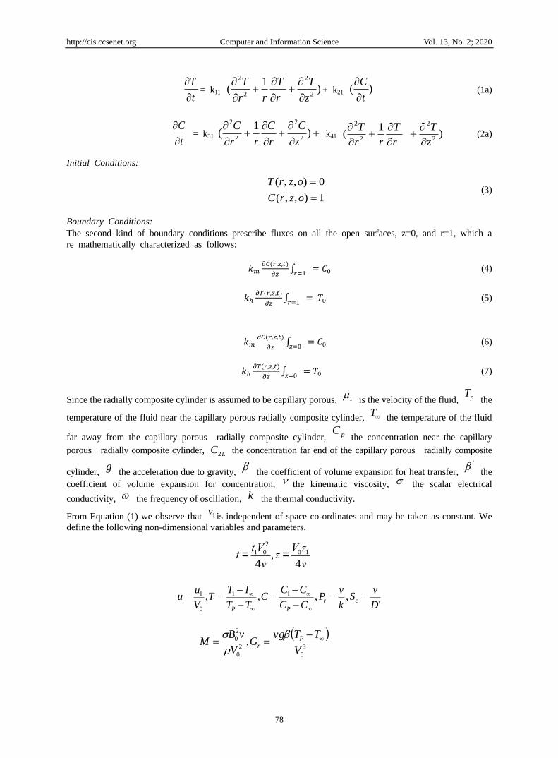
4. Mathematical Model and Numerical Solutions of Heat and Mass Transfer
4.1 Mathematical Model
Consider the Heat and Mass Transfer through a capillary porous radially composite cylinder with boundary
conditions of the second kind. Let the z-axis be directed upward along the capillary porous radially composite
cylinder and the r-axis radius of the capillary porous radially composite cylinder. Let u and v a chance to be the
speed parts along the z-and r-axes respectively. We need to compose isolate conditions for every material as both
will have distinctive properties. Since we are concerned about observing the impact of conductivities of the 2
materials, we watch their conduct under a similar initial and boundary conditions. So the first set of equations will
compare to the first material (0 < z < 2L, 0<r<a), whereas the second set relates to the second material. At that
point the heat and mass transfer equations written in the Boussinesq's form, are:
t
T
= k1 )
1(
2
2
2
2
z
T
r
T
rr
T
+ k2 )(
t
C
(1)
t
C
= k3
)
1(
2
2
2
2
z
C
r
C
rr
C k4 )
1(
2
2
2
2
z
T
r
T
rr
T
(2)
For first material, 0<z<2L, 0<r<a, t>0
Where 2L is the length of the first or second material, and r is the radius of the cylinder. Here we tak
e total radius as 1.
For second material, 0<z<2L, a<r<1, t>0 in capillary porous radial composite cylinder, the equations are:
http://cis.ccsenet.org Computer and Information Science Vol. 13, No. 2; 2020
78
t
T
= k11 )
1(
2
2
2
2
z
T
r
T
rr
T
+ k21 )(
t
C
(1a)
t
C
= k31
)
1(
2
2
2
2
z
C
r
C
rr
C k41 )
1(
2
2
2
2
z
T
r
T
rr
T
(2a)
Initial Conditions:
1),,(
0),,(
ozrC
ozrT (3)
Boundary Conditions:
The second kind of boundary conditions prescribe fluxes on all the open surfaces, z=0, and r=1, which a
re mathematically characterized as follows:
𝑘𝑚𝜕𝐶(𝑟,𝑧,𝑡)
𝜕𝑧∫
𝑟=1= 𝐶0 (4)
𝑘ℎ𝜕𝑇(𝑟,𝑧,𝑡)
𝜕𝑧∫
𝑟=1= 𝑇0 (5)
𝑘𝑚𝜕𝐶(𝑟,𝑧,𝑡)
𝜕𝑧∫
𝑧=0= 𝐶0 (6)
𝑘ℎ𝜕𝑇(𝑟,𝑧,𝑡)
𝜕𝑧∫
𝑧=0= 𝑇0 (7)
Since the radially composite cylinder is assumed to be capillary porous, 1 is the velocity of the fluid, pT the
temperature of the fluid near the capillary porous radially composite cylinder, T the temperature of the fluid
far away from the capillary porous radially composite cylinder, pC the concentration near the capillary
porous radially composite cylinder, LC2 the concentration far end of the capillary porous radially composite
cylinder, g
the acceleration due to gravity,
the coefficient of volume expansion for heat transfer, ' the
coefficient of volume expansion for concentration, the kinematic viscosity, the scalar electrical
conductivity, the frequency of oscillation, k the thermal conductivity.
From Equation (1) we observe that 1vis independent of space co-ordinates and may be taken as constant. We
define the following non-dimensional variables and parameters.
t =t1V0
2
4v, z =
V0z1
4v
',,,, 11
0
1
D
vS
k
vP
CC
CCC
TT
TTT
V
uu cr
PP
3
0
2
0
2
0 ,V
TTvgG
V
vBM P
r
http://cis.ccsenet.org Computer and Information Science Vol. 13, No. 2; 2020
79
2
0
3
0
4,
'
V
v
V
CCvgG iP
m
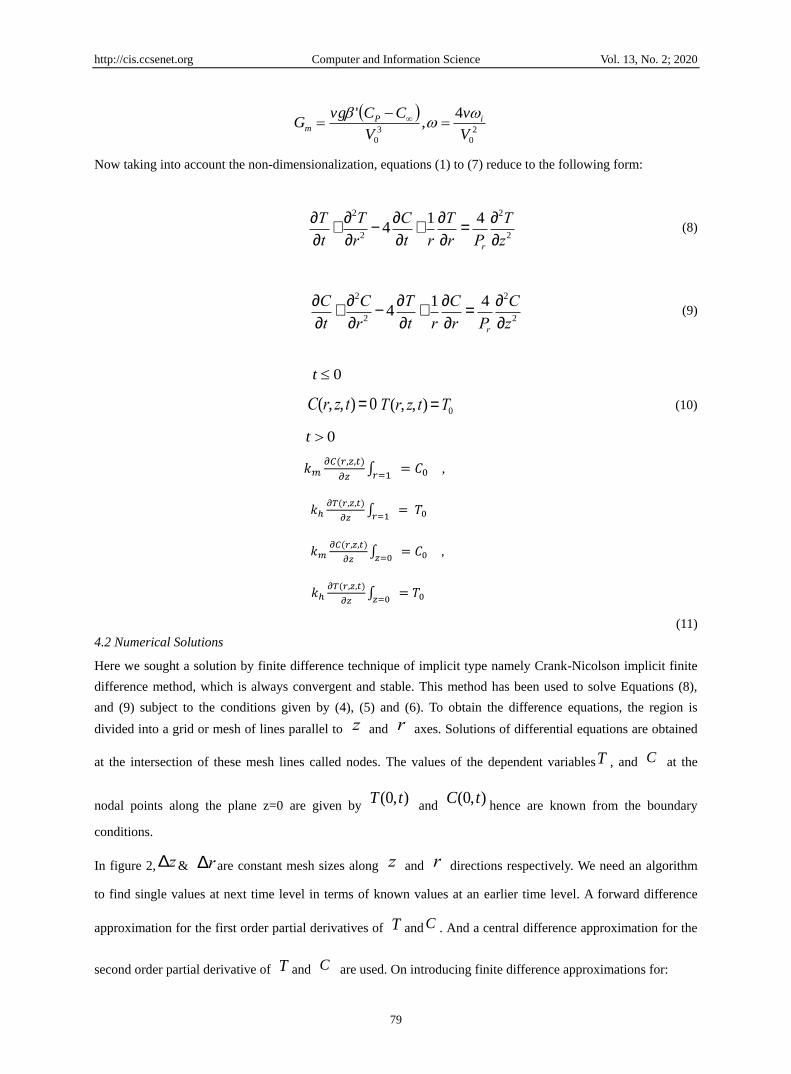
Now taking into account the non-dimensionalization, equations (1) to (7) reduce to the following form:
¶T
¶t+
¶2T
¶r2- 4
¶C
¶t+
1
r
¶T
¶r=
4
Pr
¶2T
¶z2 (8)
¶C
¶t+
¶2C
¶r2- 4
¶T
¶t+
1
r
¶C
¶r=
4
Pr
¶2C
¶z2 (9)
0t
C(r, z, t) = 0 T(r, z, t) =T0 (10)
0t
𝑘𝑚𝜕𝐶(𝑟,𝑧,𝑡)
𝜕𝑧∫
𝑟=1= 𝐶0 ,
𝑘ℎ𝜕𝑇(𝑟,𝑧,𝑡)
𝜕𝑧∫
𝑟=1= 𝑇0
𝑘𝑚𝜕𝐶(𝑟,𝑧,𝑡)
𝜕𝑧∫
𝑧=0= 𝐶0 ,
𝑘ℎ𝜕𝑇(𝑟,𝑧,𝑡)
𝜕𝑧∫
𝑧=0= 𝑇0
(11)
4.2 Numerical Solutions
Here we sought a solution by finite difference technique of implicit type namely Crank-Nicolson implicit finite
difference method, which is always convergent and stable. This method has been used to solve Equations (8),
and (9) subject to the conditions given by (4), (5) and (6). To obtain the difference equations, the region is
divided into a grid or mesh of lines parallel to z and r axes. Solutions of differential equations are obtained
at the intersection of these mesh lines called nodes. The values of the dependent variablesT , and C at the
nodal points along the plane z=0 are given by ),0( tT
and ),0( tC
hence are known from the boundary
conditions.
In figure 2, Dz& Dr are constant mesh sizes along z and r directions respectively. We need an algorithm
to find single values at next time level in terms of known values at an earlier time level. A forward difference
approximation for the first order partial derivatives of T and C . And a central difference approximation for the
second order partial derivative of T and C are used. On introducing finite difference approximations for:

http://cis.ccsenet.org Computer and Information Science Vol. 13, No. 2; 2020
80
Figure 2. Finite Difference Grid for capillary porous radially composite cylinder
For the purposes of coming up with a numerical solution to the problem, the radius of the capillary porous
radially composite cylinder is 1.0. The finite difference approximation of Equations (8) and (9) are obtained with
substituting these approximations into Equations (8) and (9) and multiplying both sides by t and after
simplifying, we let Dt
Dz( )2
= r ' =1 (the method is always stable and convergent), under this condition the above
equations can be writen as:
t
C
=
2
,, )(2(
r
CTVU jiji
+ +
2
,, )(2(
z
CTVU jiji
)
t
T
=
2
1
2
,, )2(22(
r
CTVU jiji
+
rr
VU
2
2 +
)
)2(222
,,
z
CTVU jiji
2
1
rr
VU
2

http://cis.ccsenet.org Computer and Information Science Vol. 13, No. 2; 2020
81
Let U = 1,11,1,1,1 jijijiji TTTT
Let V = 1,11,1,1,1 jijijiji CCCC
4.3 Grid Structure and Heat Continuity Condition
Figure 3a. Plane of Heat Continuity in a Composite Solid Cylinder
The plane of heat, mass continuity is the plane along the radial axis of the solid radially composite cylinder (as
shown in Fig. 3a, 3b and 3c) where the material properties change, i.e. where the two different materials are
joined or merged together. So, the grid position in the above radially composite cylinder is as depicted in the
figure 3b.
Figure 3b. Grid arrangement in a Composite Solid Cylinder
Figure 3c. Grid Position in a Composite Solid Cylinder
http://cis.ccsenet.org Computer and Information Science Vol. 13, No. 2; 2020
82
At this point of intersection, i.e., the plane of heat, mass continuity, in case of heat, the heat transfer occurs, the
temperature at the last grid point along any radius of the first material is approximately equal to the temperature
at the first grid point in the second material. Similarly, the concentration at the last grid point along any radius of
the first material is approximately equal to the concentration at the first grid point in the second material. So, the
continuity equations at the r=a can be written as follows:
𝑇1(𝑟, 𝑧𝑙 , 𝑡) = 𝑇2(𝑟, 𝑧0, 𝑡) (12)
𝐶1(𝑟, 𝑧𝑙 , 𝑡) = 𝐶2(𝑟, 𝑧0, 𝑡) (13)
𝜕𝑇1(𝑟,𝑧𝑙,𝑡)
𝜕𝑧=
𝜕𝑇2(𝑟,𝑧𝑙,𝑡)
𝜕𝑧 (14)
𝜕𝐶1(𝑟,𝑧𝑙,𝑡)
𝜕𝑧=
𝜕𝐶2(𝑟,𝑧𝑙,𝑡)
𝜕𝑧 (15)
5. Experimental Results and Discussion
5.1 Setup and Device Configuration
The experiment was executed using the CUDA Runtime Library, Quadro FX 4800 graphics card, Intel Core 2
Duo. The programming interface used was Visual Studio.
The experiments were performed using a 64-bit Lenovo ThinkStation D20 with an Intel Xeon CPU E5520 with a
processor speed of 2.27 GHZ and physical RAM of 4.00GB. The Graphics Processing Unit (GPU) used was an
NVIDIA Quadro FX 4800 with the following specifications:
CUDA Driver Version: 3.0
The total amount of global memory: 59 GB
Number of multiprocessors: 24
Number of cores: 92
The total amount of constant memory: 65536 bytes
The total amount of shared memory per block: 16384 bytes
Total number of registers available per block: 16384
Maximum number of threads per block: 512
Bandwidth:
Host to Device Bandwidth: 3412.1 (MB/s)
Device to Host Bandwidth: 3189.4 (MB/s)
Device to Device Bandwidth: 57509.6 (MB/s)
In the tests, we considered simulating heat and mass transfer differential conditions in a capillary porous radially
composite cylinder with boundary conditions of second kind utilizing numerical techniques. Our principle reason
here was to get numerical answers for Temperature T, and concentration C spread over the different points in a
capillary porous composite solid cylinder as heat and mass are transferred from one end of the capillary porous
radially composite cylinder to the next. For our investigation, we compared the closeness of the CPU and GPU
results. We additionally analysed the execution of the CPU and GPU regarding processing times of these
outcomes.
In the test setup, we are given the underlying temperature T0 and concentration C0 at point z = 0 on the capillary
porous radially composite cylinder. Likewise, there is a consistent temperature and concentration, T0, C0 always
working at the surface of the capillary porous radially composite cylinder. The temperature at the opposite end of
the capillary porous composite barrel where z = ∞ is thought to be surrounding temperature (here, assumed to be

http://cis.ccsenet.org Computer and Information Science Vol. 13, No. 2; 2020
83
zero). Additionally, the fixation at the opposite end of the capillary porous composite chamber where z = ∞ is
thought to be insignificant (≈ 0). Our underlying issue was to determine the temperature T1 and concentration C1
related with the underlying temperature and concentration respectively. We did this by utilizing the finite
difference method. Thus, we achieved initial temperature of (T0 + T1) and total initial concentration of (C0+ C1)
at z = 0. These aggregate introductory conditions were then used to perform calculations.
With the end goal of usage, we used a fixed length of the capillary porous radially composite cylinder and
fluctuated the quantity of nodal points N to be resolved in the capillary porous radially composite cylinder. Since
N is inversely proportional to the progression estimate ∆z, expanding N, diminishes ∆z and subsequently more
exact outcomes are acquired with bigger estimations of N. For simple execution in Visual Studio, we utilized the
Forward Euler Method (FEM) for calculations of the temperature and concentration distributions at each nodal
point in both the CPU and GPU. For a given array of size N, the nodes are ascertained iteratively until the point
when the estimations of temperature and concentration end up stable. In this trial, we played out the emphasis for
10 diverse time steps. After the tenth step, the estimations of the temperature and concentration wound up stable
and are recorded. We run the tests for a few distinct estimations of N and ∆z, and the error between the GPU and
CPU computed come about were progressively smaller as N expanded. Finally, our outcomes were standardized
in both the GPU and CPU.
5.2 Experimental Results
The standardized temperature and concentration conveyances at different nodes in the capillary porous radially
composite cylinder are described in Table 1 and Table 2 respectively. We can quickly observe that, at each point
in the capillary porous radially composite cylinder, the CPU and GPU figured outcomes are comparative. What's
more, the estimation of temperature is most astounding, and the estimation of concentration is least at the point
on the capillary porous radially composite cylinder where the heat and mass are always applied. As we move far
from this point, the estimations of the temperature reduce and concentration increase. At a point close to the
assigned end of the capillary porous radially composite cylinder, the estimations of the temperature approaches
zero and concentration approach one.
Table 1. Comparison of GPU and CPU Results For Capillary Porous radially composite cylinder (Concentration)
Z CPU RESULTS GPU
RESULTS
1 0.04998520 0.04867128
2 0.15996874 0.16412578
3 0.30124536 0.33657810
4 0.41235478 0.39814357
5 0.49571258 0.48953276
6 0.57741023 0.53618942
7 0.65638749 0.61023589
8 0.68896574 0.66803897
9 0.73254108 0.76520897
10 0.85891023 0.84796581
11 1 1
Table 2. Comparison of GPU and CPU Results For Capillary Porous radially composite cylinder (Temperature)
Z CPU RESULTS GPU RESULTS
1 1 1
2 0.75012489 0.79653247
3 0.70354124 0.69745863
4 0.65682143 0.65632149
5 0.57023985 0.56324178
6 0.52014563 0.52357896
7 0.46985412 0.41023659
8 0.38896745 0.37521963
9 0.33986745 0.32741563
10 0.27856932 0.24698514
11 0.18869541 0.15698452

http://cis.ccsenet.org Computer and Information Science Vol. 13, No. 2; 2020
84
Figure 4a and Figure 4b Shows the temperature and concentration distribution in the capillary porous radially
composite cylinder with 4 different radiuses.
Figure 4a
Figure 4b
Besides, we additionally assessed the execution of the GPU (NVIDIA Quadro FX 4800) as far as fathoming heat
and mass transfer conditions by contrasting its execution time with that of the CPU (Intel Xeon E5520).
To measure the execution time, similar capacities were actualized in both the gadget (GPU) and the host (CPU),
to instate the temperature and concentration and to figure the numerical arrangements. For this situation, we
gauged the execution time for various estimations of N. The chart in Figure 5 delineates the execution of the
GPU versus the CPU as far as the execution time. We run the test for N running from 10 to 599 with additions of
30 and for the most part, the GPU played out the computations a more quicker than the CPU.
When N was smaller than 80, the CPU performed the calculations faster than the GPU.
For N larger than 80 the GPU performance began to increase considerably
Figure 5a and 5b show some of our experimental results for capillary porous radially composite cylinder.
Figure 5a. Performance of GPU and CPU Implementations for capillary porous radially composite cylinder
http://cis.ccsenet.org Computer and Information Science Vol. 13, No. 2; 2020
85
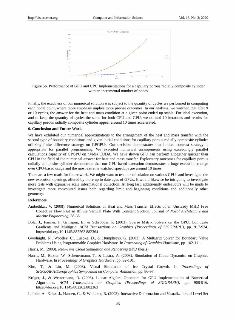
Figure 5b. Performance of GPU and CPU Implementations for a capillary porous radially composite cylinder
with an incremental number of nodes
Finally, the exactness of our numerical solution was subject to the quantity of cycles we performed in computing
each nodal point, where more emphasis implies more precise outcomes. In our analysis, we watched that after 9
or 10 cycles, the answer for the heat and mass condition at a given point ended up stable. For ideal execution,
and to keep the quantity of cycles the same for both CPU and GPU, we utilized 10 iterations and results for
capillary porous radially composite cylinder appear around 10 times accelerated.
6. Conclusion and Future Work
We have exhibited our numerical approximations to the arrangement of the heat and mass transfer with the
second type of boundary conditions and given initial conditions for capillary porous radially composite cylinder
utilizing finite difference strategy on GPGPUs. Our decision demonstrates that limited contrast strategy is
appropriate for parallel programming. We executed numerical arrangements using exceedingly parallel
calculations capacity of GPGPU on nVidia CUDA. We have shown GPU can perform altogether quicker than
CPU in the field of the numerical answer for heat and mass transfer. Exploratory outcomes for capillary porous
radially composite cylinder demonstrate that our GPU-based execution demonstrates a huge execution change
over CPU-based usage and the most extreme watched speedups are around 10 times.
There are a few roads for future work. We might want to test our calculation on various GPUs and investigate the
new execution openings offered by more up to date ages of GPUs. It would likewise be intriguing to investigate
more tests with expansive scale informational collection. At long last, additionally endeavours will be made to
investigate more convoluted issues both regarding limit and beginning conditions and additionally other
geometry.
References
Ambethkar, V. (2008). Numerical Solutions of Heat and Mass Transfer Effects of an Unsteady MHD Free
Conective Flow Past an Iffinite Vertical Plate With Constant Suction. Journal of Naval Architecture and
Marine Engineering, 28-36.
Bolz, J., Farmer, I., Grinspun, E., & Schröoder, P. (2003). Sparse Matrix Solvers on the GPU: Conjugate
Gradients and Multigrid. ACM Transactions on Graphics (Proceedings of SIGGRAPH), pp. 917-924.
https://doi.org/10.1145/882262.882364
Goodnight, N., Woolley, C., Luebke, D., & Humphreys, G. (2003). A Multigrid Solver for Boundary Value
Problems Using Programmable Graphics Hardware. In Proceeding of Graphics Hardware, pp. 102-111.
Harris, M. (2003). Real-Time Cloud Simulation and Rendering (PhD thesis).
Harris, M., Baxter, W., Scheuermann, T., & Lastra, A. (2003). Simulation of Cloud Dynamics on Graphics
Hardware. In Proceedings of Graphics Hardware, pp. 92-101.
Kim, T., & Lin, M. (2003). Visual Simulation of Ice Crystal Growth. In Proceedings of
SIGGRAPH/Eurographics Symposium on Computer Amination, pp. 86-97.
Krüger, J., & Westermann, R. (2003). Linear Algebra Operators for GPU Implementation of Numerical
Algorithms. ACM Transactions on Graphics (Proceedings of SIGGRAPH), pp. 908-916.
https://doi.org/10.1145/882262.882363
Lefohn, A., Kniss, J., Hansen, C., & Whitaker, R. (2003). Interactive Deformation and Visualization of Level Set

http://cis.ccsenet.org Computer and Information Science Vol. 13, No. 2; 2020
86
Surfaces Using Graphics Hardware. In IEEE Visualization, pp. 75-82. Retrived from http://www.gpgpu.org
Luikov, A. V. (1966). Heat and Mass Transfer in Capillary Porous Bodies. Pergamon Press.
https://doi.org/10.1016/B978-1-4832-0065-1.50010-6
Narang, H., & Nekkanti, R. (2001). Wavelet-based Solution to Time-dependent Two-point Initial Boundary
Value Problems with Non-Periodic Boundary Conditions. Proceedings of the IATED International
Conference Signal Processing, Pattern Recognition & Applications, Rhodes, Greece.
Narang, H., & Nekkanti, R. (2001). Wavelet-based solutions to problems involving Parabolic Equations. In
Proceedings of the IATED International Conference Signal Processing, Pattern Recognition & Applications,
Greece.
Narang, H., & Nekkanti, R. (2002). Wavelet-based Solution of Boundary Value Problems involving Hyperbolic
Equations. In Proceedings from the IATED International Conference Signal Processing, Pattern
Recognition & Applications.
Narang, H., & Nekkanti, R. (2002). Wavelet-Based Solution to Elliptic Two-Point Boundary Value Problems
with Non-Periodic Boundary Conditions. In Proceedings from the WSEAS international conference in
Signal, Speech, and Image processing.
Narang, H., & Nekkanti, R. (2003). Wavelet-Based Solution to Some Time-Dependent Two-Point Initial
Boundary Value Problems with Non-Linear Non-Periodic Boundary Conditions. In International
Conference on Scientific computation and differential equations, SCICADE 2003, Trondheim, Norway, June
30. https://doi.org/10.1115/FEDSM2003-45030
Narang, H., & Nekkanti, R. (2004). Wavelet based Solution to Time-Dependent Two Point Initial Boundary
Value Problems with Non-Periodic Boundary Conditions involving High Intensity Heat and Mass Transfer
in Capillary Porous Bodies. In IATED International Conference proceedings, Gainesville, FL.
https://doi.org/10.1115/FEDSM2003-45030
Narang, H., Wu, F., & Mohammed, A. R. (2017). An Efficient Solution of Heat and Mass Transfer Equations
using Programmable General Purpose Processing Unit under Natural Boundary Conditions in Capillary
Porous Solid and Hollow Cylinder. International Advanced Research Journal in Science, Engineering and
Technology, 4.
Narang, H., Wu, F., & Mohammed, A. R. (2018). An Efficient Solution of Heat and Mass Transfer Equations
using Programmable General Purpose Processing Unit under Natural Boundary Conditions in Capillary
Porous Solid and Hollow Cylinder. Journal of Computer and Communiction, 6(7).
https://doi.org/10.4236/jcc.2018.69003
Narang, H., Wu, F., & Mohammed, A. R. (2019. An Efficient Solution of Heat and Mass Transfer Equations
using Programmable General Purpose Processing Unit under Boundary Conditions of third kind in
Capillary Porous radially composite Cylinder. Journal of Computer and Compmmunication, 7(6).
Narang, H., Wu, F., Ogunniyan, A., & Mohammed, A. R. (2017) An Efficient Acceleration of Solving Heat and
Mass Transfer Equations with second kind boundary and Initial conditions in solid and hollow cylinder
using programmable graphics hardware. Journal of Computations & Modellling. Scienpress Ltd, 201x
NVIDIA Corporation. NVIDIA Programming Guide 2.3. Retrieved from www.nvidia.com
Owens, J. D., Luebke, D., Govindaraju, N., Harris, M., Krger, J., Lefohn, A. E., Purcell, T. J. (2007). A survey
of general-purpose computation on graphics hardware. Computer Graphics Forum, 26(1), 80-113.
https://doi.org/10.1111/j.1467-8659.2007.01012.x
Copyrights
Copyright for this article is retained by the author(s), with first publication rights granted to the journal.
This is an open-access article distributed under the terms and conditions of the Creative Commons Attribution
license (http://creativecommons.org/licenses/by/4.0/).