An economical approach to autopilot development and ...
19
1 American Institute of Aeronautics and Astronautics An economical approach to autopilot development and integration Karl Schulze, Andrew Abramson, Brian Rogan Cornell University, Ithaca, NY, 14853 Autonomous Unmanned Aerial Vehicles (UAVs) are prohibitively expensive for use in civilian surveillance applications. This is in large part due to the manufactures need to recoup the costs of research and development. The more intelligence that is incorporated into unmanned vehicles, the more expensive it is to validate. At Cornell University an autopilot system for UAVs has been developed and integrated into a fixed wing aircraft on a budget of $15,000 and 3000 man hours dispersed over 6 months. This document describes the modern cost saving approaches used for developing the UAV, as well as the individual sub systems and the resulting UAV. I. Introduction Cornell University undergraduate students have developed a custom, autonomous, aerial vehicle package for use in local research activities as well as to enter in AUVSI’s 1 second annual autonomous aerial vehicle competition. The package consists of off-the-shelf hardware components combined with custom software, placed in a standard fixed wing aircraft. The airframe is a SIG Rascal 110 ARF 2 with a wingspan of just over 9 feet and a dry weight of under twenty pounds. The aircraft is powered by a 3W 24CC 3 gas engine. The hardware package consists of a GPS receiver, a 3-axis orientation gyroscope, and a set of pressure sensors to measure air speed and altitude. The communications hardware consists of two radio modems, operating at 900Mhz and 2.4Ghz, allowing over-air speeds of up to 56kbs. The aircraft handles all autonomous control onboard, however it is equipped with full telemetry systems to support ground monitoring, and if necessary, mission modifications. The telemetry system allows for caching on the ground through a single point of communication, as well as encrypted over the air communication. In addition to basic telemetry systems, live video is transmitted to the ground, which is used to gather target and object location information. The paramount concern with Unmanned Aircraft is safety. The system utilizes many levels of fail safe, including system loitering, sensor failure detection and management as well as a system shutdown in the case of complete signal loss. The autopilot system is capable of flying a series of GPS coordinates, calculating wind vectors and appropriate cropping angles, surveying large areas and is easily extended through its modular design. This aircraft represents the second evolution of the project to develop an affordable, versatile autopilot system. The first generation project, detailed in the 2003 AIAA paper, achieved many of the target objectives, but was not as extendable, or as reliable as needed. This year the project has been completely reengineered, starting with a more suitable airframe, a more reliable component set, and a new software suite. 1 AUVSI – Association for Unmanned Vehicle Systems International, http://www.auvsi.org/ 2 SIG Rascal ARF 110 – 110” wingspan almost ready to fly radio control aircraft kit, http://www.sigmfg.com/ 3 3W 24CC – a 3W Modellmotoren engine, this engine provides 2.5 horse power at 1,500 – 8,500 RPM, and only weighs 2.96 lbs including the ignition system, http://www.3w-modellmotoren.de/
Transcript of An economical approach to autopilot development and ...
1 American Institute of Aeronautics and Astronautics
An economical approach to autopilot development and integration
Karl Schulze, Andrew Abramson, Brian Rogan Cornell University, Ithaca, NY, 14853
Autonomous Unmanned Aerial Vehicles (UAVs) are prohibitively expensive for use in civilian surveillance applications. This is in large part due to the manufactures need to recoup the costs of research and development. The more intelligence that is incorporated into unmanned vehicles, the more expensive it is to validate. At Cornell University an autopilot system for UAVs has been developed and integrated into a fixed wing aircraft on a budget of $15,000 and 3000 man hours dispersed over 6 months. This document describes the modern cost saving approaches used for developing the UAV, as well as the individual sub systems and the resulting UAV.
I. Introduction Cornell University undergraduate students have developed a custom, autonomous, aerial vehicle package for use
in local research activities as well as to enter in AUVSI’s1 second annual autonomous aerial vehicle competition. The package consists of off-the-shelf hardware components combined with custom software, placed in a standard fixed wing aircraft. The airframe is a SIG Rascal 110 ARF2 with a wingspan of just over 9 feet and a dry weight of under twenty pounds. The aircraft is powered by a 3W 24CC3 gas engine. The hardware package consists of a GPS receiver, a 3-axis orientation gyroscope, and a set of pressure sensors to measure air speed and altitude. The communications hardware consists of two radio modems, operating at 900Mhz and 2.4Ghz, allowing over-air speeds of up to 56kbs.
The aircraft handles all autonomous control onboard, however it is equipped with full telemetry systems to support ground monitoring, and if necessary, mission modifications. The telemetry system allows for caching on the ground through a single point of communication, as well as encrypted over the air communication. In addition to basic telemetry systems, live video is transmitted to the ground, which is used to gather target and object location information.
The paramount concern with Unmanned Aircraft is safety. The system utilizes many levels of fail safe, including system loitering, sensor failure detection and management as well as a system shutdown in the case of complete signal loss.
The autopilot system is capable of flying a series of GPS coordinates, calculating wind vectors and appropriate cropping angles, surveying large areas and is easily extended through its modular design.
This aircraft represents the second evolution of the project to develop an affordable, versatile autopilot system. The first generation project, detailed in the 2003 AIAA paper, achieved many of the target objectives, but was not as extendable, or as reliable as needed. This year the project has been completely reengineered, starting with a more suitable airframe, a more reliable component set, and a new software suite.
1 AUVSI – Association for Unmanned Vehicle Systems International, http://www.auvsi.org/ 2 SIG Rascal ARF 110 – 110” wingspan almost ready to fly radio control aircraft kit, http://www.sigmfg.com/ 3 3W 24CC – a 3W Modellmotoren engine, this engine provides 2.5 horse power at 1,500 – 8,500 RPM, and only weighs 2.96 lbs including the ignition system, http://www.3w-modellmotoren.de/

American Institute of Aeronautics and Astronautics
2
II. Design Objectives The goal of this project has been to develop an autopilot system which is suitable for civilian applications,
including forest fire surveillance, police traffic/search and rescue surveillance, weather sampling, etc. In order to develop a practical aircraft, it has to be affordable, safe, reliable, and capable of a diverse range of missions.
A. Economy To be practical and affordable enough for integration into all levels of commercial and research need, the cost of
autonomous flight control system had to stay below $5,000.00 USD. This figure was based on benchmarking of currently available autopilot systems, and costs associated with guidance and telemetry of baseline Remotely Piloted Vehicles (RPVs). Limited available resources also dictated a need to keep prototype system costs below this level. Equivalent commercial development costs also had to be kept below $500,000, as anything higher would not represent a practical business opportunity to make these vehicles available to the market.
B. Safety An autonomous flight control system inherently removes human operator intervention from vehicle
functionality. The capability of an aircraft of considerable mass, traveling at high velocity, to inflict damage to people or property is substantial. It was critical that the flight control system would include several modes of flight termination in case of emergency or flight control system failure.
C. Capability The system must be able to navigate long and short distances with the ability to adapt to wind conditions and
altitude constraints. This involves the ability to fly direct paths between waypoints, and accommodating for weather conditions to minimize cross track errors. The guidance package must be adaptable to allow for integration with a variety of fixed wing platforms. Furthermore, the competition requires that the vehicles be able to automatically take off and land, as well as carry a video surveillance payload.
D. Reliability & Maintainability This is directly related to system safety, and critical to functionality. In order to offer a viable autonomous flight
solution for any application, especially research applications where repeated data loss can setback a research program considerably, it is critical that the system be robust and capable of continuous functionality. Mission times of one hour with provisions for a thirty minute reserve, were established as the basis for operational capability of the prototype system. Previous experience with research data collecting was used to establish this constraint, which in turn helped with the design of a suitable power supply and distribution network.
E. Physical Constraints The mass and physical dimensions of the flight control system had to be such that they were compatible not only
with the prototype UAV, but also with a range of likely RPVs which were candidates for conversion to autonomous flight. Balancing the need for a sizable payload, but the convenience of a small airframe, a nominal package mass of 2kg was established. Physical size was not as critical, as it was assumed that dimension would be constrained by mass restrictions, but a maximum payload volume of 6000 cm3 was established based on the UAV prototype airframe.
III. System Overview The system is broken up into two areas of interest, the hardware, and the software. The hardware platform
represents a diverse base of readily available components, assembled together to create a lightweight, reliable base for the autonomous software package. The software platform represents the most unique combination of the readily available Microsoft Windows operating system with the Microsoft.Net virtual machine runtime and our custom autopilot modules.
The choice of the Windows operating system often brings immediate concerns to such a critical application; however, the net result is not unlike the systems first employed inside of an Airbus commercial aircraft4. The Airbus 4 Airbus commercial aircraft – Airbus was the first commercial airline company to introduce a fly by wire control system in 1988, in which a computer interprets inputs and adjusts the control surfaces accordingly, without the pilots controls being interfaced directly.
American Institute of Aeronautics and Astronautics
3
system utilized six i386 desktop processors, each running a custom operating system, abstracting machine operations with a virtual machine running each process. This system allowed the operating system to monitor each process’s health, and in the case of failure, restart the process, without locking up the hardware. The windows embedded operating system is utilized in the aircraft to replace the custom operating system on the airbus autopilot, and the Microsoft .Net framework is used to replace the custom virtual machine. This combination is what allowed the project to be developed so rapidly, and has led to a reliable system.
A. Hardware Overview The autopilot system is designed to be very modular and can be equipped in any given fixed-wing aircraft able to
carry its payload mass within a matter of hours. Due to the high risk of flight, each component is heavily protected for hard impacts, and isolated from the vibrations of the engine and rigors of flight. Each electronic component is carefully faraday caged to prevent RF interference and is held in place by vibration resistant rubber mounts.
1. Airframe The prototype airframe is a SIG Rascal 1105, heavily modified RC aircraft. The Rascal comes as an
unassembled kit, but has been constructed and adapted for this payload. Modifications on the airframe include the replacement of the factory built tail with a custom lifting tail, moving
the center of lift further towards the rear of the plane. Given the heavier than designed wing loadings this airframe is experiencing, we have installed large in-wing flaps to allow for a slower stall speed and improved takeoff and landing characteristics.
Airframe Specifications: Wingspan: 110” Wing Area: 1522 sq. in. Length: 75-3/4” Weight: 13 lbs. Wing Loading: 16.6 - 19.7 oz./sq. ft. 7 RC servos Table 2: Airframe specifications The research and development phase of UAV development is extraordinarily risky, and often entails
unpredictable accidents. In order to maintain steady development the project required four backup airframes, which could be used if an airframe is lost. This insures that development is not halted by an unfortunate accident, but rather that an accident can be analyzed and the project may resume without delay.
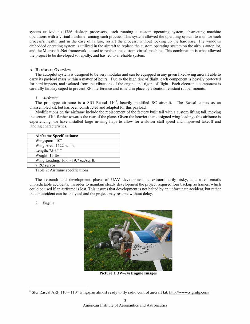
2. Engine
Picture 1. 3W-24i Engine Images
5 SIG Rascal ARF 110 – 110” wingspan almost ready to fly radio control aircraft kit, http://www.sigmfg.com/

American Institute of Aeronautics and Astronautics
4
The prototype aircraft is powered by a 3W-24i gasoline engine manufactured by 3-W Modellmotoren6. This engine, designed for “giant-scale” sized airframes, has a cylinder capacity of 1.42 cu inches and weights just 2.65 lbs. The 18” 2-bladed propeller spins at 8,500 RPM, generating as much as 2.5 HP. This engine is powerful enough to easily carry the payload, while efficient enough to deliver flight times of up to an hour and a half.
3. Batteries and Power System In order to power the large array of different sensors and computing equipment on the aircraft, a battery system
with a significant capacity is needed. The total power draw of all the autopilot components is as much as 15W at 5V DC. When selecting a battery solution, a pack with high capacity and low weight was a necessity. Lithium Polymer technology provides the extremely high capacity needed to power our system, but in a lightweight, compact form factor. Kokam 3-cell lithium polymer7 packs are used, each providing 3270mAH creating a combined 12V pack. Weighing less than 212g, this pack will power the system for as long as two hours.
Picture 2. Auxiliary Power Hookup
The majority of time during development test flights is spent with the aircraft on the ground. To prevent the loss
of on board battery power, we have developed a system to circumvent the onboard packs and to provide external power. While on the ground, any 12V DC source, such as high capacity lead acid packs, can be plugged into a 2 prong Lemo Outlet (Picture 2) on the side of the plane, powering the entire system from auxiliary power.
In order to provide a regulated 5 Volts to our computer and sensitive electronic device, we selected a Beta Dyne8 25S5/12 high-performance isolated DC/DC converter, weighing just 59g and providing 86% efficiency, to power the computer and 5V sensor devices.
4. Computer System The autopilot software runs on an onboard Technoland PC/104+ form factor computer9. The computer is an 800
MHz Crusoe10 with 180 MB RAM, providing ample computing power while keeping power usage and heat
6 3W 24CC – a 3W Modellmotoren engine, this engine provides 2.5 horse power at 1,500 – 8,500 RPM, and only weighs 2.96 lbs including the ignition system, http://www.3w-modellmotoren.de/ 7 Kokam 3 cell lithium polymer – lithium polymer batteries offer energy densities of 5.6 grams / watt, with 3 cells in series, the nominal system voltage is 11.7 volts, and have a capacity of 76.5 watt hours, more than long enough to run all of our equipment. https://www.fmadirect.com/ 8 Beta Dyne DC/DC converter – this device used switching in order to regulate our ~11.7 volt system power down to precisely 5 volts for input to our electronics systems. http://www.beta-dyne.com/ 9 Technoland PC/104+ form factor computer – this form factor measures just 3.75” in. x 3.54” in. and contains an i386 processor, hard drive interface, floppy drive interface, USB ports, two serial ports, two ps2 ports, an integrated network, and consumes just 12 watts. http://www.technoland.com/ 10 Crusoe – an i386 compatible processor, which implements several of the instruction sets in a software layer, allowing the processor to draw very little power. http://www.transmeta.com/

American Institute of Aeronautics and Astronautics
5
generation to a minimum. In addition, a USB11 to serial device provides four additional RS232 communication ports12 while avoiding IRQ conflicts13.
The computer runs Microsoft Windows XP Embedded14, allowing for a very small operating system footprint while maintaining the full functionality of the Microsoft .NET15 architecture. The system runs off two 512 MB compact flash cards, providing a storage system with no moving parts, able to withstand up to 10,000 G’s. One compact flash card holds the operating system in a protected write mode, while the other stores a real-time log of in-flight variables. In the case of an unknown failure, the problem can be diagnosed by examining the log files, even if the vehicle crashes.
5. GPS Receiver
Picture 3. Garmin GPS 15H
The plane obtains 3D positional data at 1Hz from a Garmin 15H GPS receiver16. The GPS module is extremely
light and provides improved accuracy through the use of the Wide Area Augmentation System, and DGPS commands sent to the plane when available. Able to run off 8-40 VDC, the Garmin 15H weights just 15g and outputs its data in NEMA17 standard over 4800 baud RS232 serial.
11 USB – universal serial bus provides a high speed interface to devices, and allows for up to 127 devices to be attached to a single port. This greatly expands the ability to attach future device through conversion or otherwise. 12 RS232 Communication Ports – this is a serial protocol in which data is transferred over a three line system, send, receive, and a ground reference. This is a very common system, as it is easily implemented on small microprocessor devices, and is used as the medium of communications within the aircraft. 13 IRQ – Interrupt request line – this is a computer resource, and provides a means for an input-output operation to notify the processor of its current actions. There are only 15 IRQ lines available on the Technoland computer, which limits the number of devices that can directly talk to the CPU. 14 Windows XP Embedded – this operating system is derived from Microsoft Windows XP’s kernel, and contains all of the elements of Windows XP Professional, however it has the ability to specify exactly which components of the kernel the end user would like to install, and allows the complete operating system to be installed on a small 200 mb foot print, with all of the needed capabilities of the full Windows XP kernel. 15 Microsoft .NET framework – This is a virtual machine architecture, which runs within the Windows XP Embedded environment, and allows for a layer of abstraction between the flight application and the hardware. 16 Garmin 15H GPS receiver – this is a small OEM Global Positioning System device, which is able to monitor up to 12 GPS satellites as well as to receive Wide Area Augmentation Systems (WAAS) updates. This provides a very high degree of accuracy in a GPS system in a package which weighs just 15 grams. 17 NEMA - National Marine Electronics Association – organizing body, which has defined the protocol for communications between common devices including GPS, radar, plot charting, compasses, etc. The NMEA protocol 0183 defines the sentence structure used to communicate with the Garmin GPS, and is implemented over standard serial.

American Institute of Aeronautics and Astronautics
6
6. Orientation Sensor
Picture 4. Microstrain 3DM-G Gyro
The Microstrain 3DM-G gyro18 is used to provide 3-DOF state information. This sensor combines three angular
rate gyros with three orthogonal accelerometers and three magnetometers to provide pitch, yaw, and roll readings accurate to .10 degrees with .01 degrees of precision. The 3DM-G outputs all nine sensor values at 100Hz. A 9V DC regulator provides the 5.2V-11V power required by the gyroscope, and the entire package weighs 40 grams.
7. Altitude & Airspeed Sensor In order to measure airspeed and altitude, two SenSys ACSX19 analog pressure sensors are placed in the plane.
One measures absolute pressure between 0 and 15 PSI, translating to the altitude, and referenced to ground level. The other measures differential pressure between the plane’s static pressure reference and the kinetic pressure reference at a pitot tube located in the wing, translating to speed. We developed a custom analog to digital board, based on an Atmel microcontroller20 and a 24-bit analog to digital converter. The microcontroller provides a filtered output at 20 hz to the computer for appropriate altitude conversions.
8. Communications and Trust While the aircraft operates entirely independently, controllers on the ground require constant communication
with the plane in order to monitor telemetry and surveillance information in real time. Furthermore, controllers may provide mission updates based on changing information, or they may need to take control of the aircraft if something should go wrong with the onboard sensors.
The largest issue with UAV development is the sense of trust. Before an aircraft may fly itself, ground operators must understand each component of the onboard decision management, and trust the aircraft to make correct decisions in flight. This process is very tedious because each module has to be integrated separately then finally allowed to operate on the aircraft under close supervision. It is the supervision phase which requires the greatest amount of ground interaction and extensive use of telemetry systems.
Each telemetry system has been carefully selected in order to insure that it will not cause interference with the other systems. Each device has been faraday caged and all transmission cables in the system have been shielded as not to broadcast any interfering signals.
18 Microstrain 3DM-G gyro – This gyro provides a very reliable method to determine the pitch, yaw, and roll of the aircraft at any given time. The Microstrain gyro was selected for its use of all solid state equipment, extreme durability and weighs only 40 grams. http://www.microstrain.com/ 19 SenSys ACSX – These pressure sensors output a 5 volt analog output, allowing us to sample at 24 bit resolution. 20 Atmel Microcontroller – inteagrates analog to digitial communications, and serial communications. http://www.atmel.com/

American Institute of Aeronautics and Astronautics
7
9. Communication Hardware In order to maintain constant communication with the ground station, two radio modems are used. A Maxstream
9XStream21 900 MHz serial modem, capable of a 19.2 Kbps over-air transfer rates, is responsible for data packets sent to the plane. Working in conjunction with the Maxstream unit is Coyote Datacomm 2.4 GHz 56 Kbps radio modem, used for downstream communication from the plane. We are using two radios, as each modem is a half duplex unit, and we wanted to insure minimum interference for each link by using very different frequencies for upstream and downstream communication (2.4 GHz and 900 MHz). Both modems have an effective line of sight range of over 5 miles, allowing users on the ground to view in-flight variables as well as provide the ability to change mission parameters even if the plane is out of visible range.
10. Video and Imaging A Panasonic CMH11222 470 line NTSC camera is mounted in the midsection of the airframe, providing a 53
degree overhead view of the area below the plane. This video is transmitted to the ground using a TXA5-RCb 1 watt ATV Transmitter board23. The ATV transmitter uses the 439Mhz HAM24 band, with a cross-dipole antenna to provide a clear picture over channel 60 TV up to several miles away. The real time video system will allow the judges to verify the vehicle has flown directly over the targets. The video is digitized on the ground and indexed with the GPS telemetry received over the radio modems to quickly allow an operator to accurately pinpoint the location of objects on the ground.
11. Receivers and Failsafe The airplane uses a pair of custom FMA Direct FS8 receivers25 for dual redundant control from a transmitter on
the ground. Each receiver controls half of the plane, allowing an emergency landing in the case of a failed component. The FS8 receivers have been modified to allow our autopilot computer to send commands to actuate the control surfaces, and the FS8 determines whether to pass the computer commands, or the manual commands, based on a switch on the ground transmitter. The FS8 receiver uses 8 channel digital signature recognition26, reducing the possibility of radio interference, even from a transmitter on the same frequency. The receivers are also equipped with a programmable fail safe mode, which actuates the flight surfaces to a set position in the case of a lost signal. Furthermore, ground operators have the ability to force the transition between autonomous and manual flight via a channel on the radio. We have also added a secondary level of protection such if the plane flies out of range of the transmitter it immediately shuts down all other electronics on board in case they are interfering. This will provide the pilot a chance to recover the plane, as we can safely assume that the plane will only erroneously fly out of range during development.
21 Maxstream serial modem – This device emulates an RS232 connection through a pair of wireless transceivers. http://www.maxstream.com/ 22 Panasonic CMH112 – This camera adjusts for light through frame exposure rather than adjusting the iris, critical for field of view calculations. http://rock2000.com/Company/CBC-Chugai/CMH112_-_CMH212_Datasheet.pdf 23 TXA5-RCb 1 watt ATV transmitter board – a transmitter which sends a video signal through analoug means on Amateur radio frequencies. http://www.hamtv.org 24 HAM – amateur radio, http://www.arrl.org 25 FMA Direct FS8 receivers – FMA direct makes RC aircraft receivers, as well as small electronics for drone aircraft, and other applications. Their latest receiver, the FS8, provides a reliable mechanism to manually control the plane, and to switch between autonomous and manual control. – http:// 26 Digital signature recognition – The FMA Direct FS8 receivers analyze the signal it receives and locks on to the particular signature of a given transmitter, and is able to overcome other signal sources, even if they are on the same channel.

American Institute of Aeronautics and Astronautics
8
12. Connectors
Picture 5. Lemo P-Series Connectors
In order modularize the electronic components within the airframe, Lemo P-Series 5-pin27 connectors have been
used to connect each device with the computer. Six sockets are mounted on the side of the computer box, allowing devices to plug into the system with just one cable. The five wire cable provides the varying voltage and signals necessary to connect to any of our devices. This has resulted in the ability to interchange any of the sensors or replacing them with a different device, without having to rewire the internal aircraft ports.
13. Ground Station
Picture 6. Ground Station Case
The ground station consists of a Versalogic Panther 400Mhz PC/104+28 computer embedded in a 7” x 10” x
18” Platt heavy duty case. Connectors allow the two radio modems to be set up along side the case, and easy access to various I/O ports such as keyboard, mouse, Ethernet, and VGA. The computer and accessories are powered by two 12V 12Ah Lead-Acid batteries, providing more than six hours of power to the system. This allows for easy transportation and setup at a remote field location.
27 Lemo P-Series 5-Pin Connector – small industrial connector, used to interface with our devices. http://www.lemo.com 28 Versalogic Panther 400Mhz PC/104+ - Similar to the Technoland computer, this is a full i386 architecture motherboard in a 3.74” x 3.72” board. http://www.versalogic.com

American Institute of Aeronautics and Astronautics
9
B. Software Overview At a high level, the software is divided into three separate components. First, there is the Prometheus aircraft
software29 which is run on the vehicle and is responsible for the actual control of the plane, including using Feedback algorithms to move the control surfaces.
As a result of the low speed and high latency of the telemetry connection it is necessary to introduce a ground station, which is the only piece of software that communicates with the plane directly. The ground station software runs a modified version of the aircraft software and acts as a gateway to allow many clients to connect to the plane, see appendix A for an object diagram. As such, the ground station is responsible for the caching of data coming down from the plane, as well as the propagation of commands from clients up to the plane.
The final application layer is made up by a number of client applications, each of which connects to the ground station via Ethernet. There are many choices for communication, including .NET remoting and Web Services30. The use of Web Services allows for platform transparency, communicating on a common network protocol. For example, there are clients for both the PC and the Pocket PC31. In short, the technologies that we utilize for ground connectivity enable the development of a wide body of heterogeneous clients to better the exchange of information to people that need it.
1. Serial Communications As was already mentioned, communication between the plane and the ground station is through low speed serial
modems. In order to facilitate this we developed a custom serial line protocol which is able to cope with the slow speed and the fact that the serial connection is potentially unreliable. To overcome loss issues, the data is streamed in packets, each of which is hashed to insure integrity. Each packet is then sequenced to ensure that missing packets can be detected, and saved on a network stack that allows dropped or corrupted packets to be resent. The packet design also contains quality-of-service bits to differentiate between command data, which needs to be received and “info” data, which if dropped is not a problem, because newer info will supersede it shortly. The packet design also contains a separate link control layer that makes it transparent to the rest of the Prometheus system when command packets are being acknowledged, or data resending is necessary.
Packets are handled by a series of classes which are designated Packet Handlers, and are responsible for encoding and decoding command information over the serial link. By using .Net reflection32 at runtime, Prometheus automatically discovers these packet handlers and uses them; adding new command messages to the telemetry system takes minimal time and effort, and as such is highly extensible.
Additionally, the system has the capability to support pluggable encryption modules. Though currently the encryption scheme used is relatively simple, using single DES33 as a proof of concept, any type of encryption can be plugged in by satisfying an interface. This will allow customers to implement any encryption scheme that they desire, including proprietary schemes in the case of military applications.
2. Interfacing with Hardware In order to facilitate communications with the hardware devices, Prometheus supports a model for dynamically
loadable drivers. This framework is currently used solely to interface with hardware, but this is not a design
29 Prometheus aircraft software – this is the name for the application which runs on the aircraft, and is responsible for all autonomous actions, and for controlling real time flight. 30 .NET remoting and Web Services – These technologies allow for communication between applications over a network. This is important as it allows for network transparency and platform independence. 31 Pocket PC – a hand held computer capable of running Windows CE, and is used as a regular computer, running a version of the ground station software. 32 .Net Reflection – This technology allows an application running within the .Net virtual machine framework to communicate with the virtual machine about object information and organization. This process allows the software to dynamically become aware of new modules, such as encryption. 33 Single DES encryption – uses a 56-bit key in order to encrypt the data in packets for transmission. Each side must negotiate the key before communications may take place. This algorithm has been considered relatively weak by modern standards, as the speed of computers has made it possible to crack Single DES through the brute force method of trying every single combination.

American Institute of Aeronautics and Astronautics
10
restriction; drivers can be implemented for any purpose. For example, drivers which interface with log files are under development, in order to allow replaying of logged data within the same framework.
The driver system allows for the creation of driver profiles, so that for example, one set of drivers can be loaded when bench-testing, another on the vehicle, and yet another on a different aircraft, possibly using different hardware. This allows the system to be easily adaptable to many different configurations. This flexibility greatly improves the reusability of the platform, no longer making it hardware dependant, and allowing end users to implement this package on a larger variety of sensors.
Drivers are provided a common shared memory space, managed by a series of mutex34 locks on the stored space. This provides the primary process for inter-thread communication, allowing drives to reflect their most recent data in the shared memory space, and control algorithms to respond to new data and to output new control surface positions.
3. Mission Management Mission management is at the heart of the aircraft’s autonomous behavior. It is responsible for defining the high
level objectives for the mission; these objectives are then converted to lower level navigation commands and maneuvers, which are passed down to the inner control loops.
The mission management framework is centered on the abstract concept of a frame, which is a measurable segment of the mission, with decided criteria for termination. The mission is broken up into many frames and each frame is allowed to set intermediate goals for the feedback loops until it informs the mission manager that it is completed, at which point the next mission frame is loaded. Additionally, the current mission frame is allowed to specify which setup it requires for the feedback loops. This allows the software to perform many different types of maneuvers without requiring invasive changes. This will be discussed in more detail in the next section.
4. Failover Modes Safety is of paramount concern in UAVs. The consequences of an out of control aircraft could be catastrophic,
given the wrong circumstances. Our vehicle is targeted to be as cost effective as possible and as such, we have chosen not to utilize a large number of redundant equipment, but to use highly reliable components. In the case of failure, there is a very decisive mapping of failover modes. For example, if GPS lock is lost, the current mission frame is frozen, and the aircraft enters into a large radius circle until a signal is reacquired, or a manual pilot intervenes. If gyro information is lost, the aircraft attempts to roll over to a secondary (appreciably less expensive) gyro in the receiver. All of these situations are handled by the failover manager, which allows custom actions to be associated with failover conditions. When modules encounter these failure conditions, they inform the failover manager, which takes suitable action. When the failure situation terminates, then control passes back to the displaced modules normally responsible for the previously failed actions, and the mission resumes.
5. Clients The information above describes how the system works in-flight, however for testing purposes, and also for the
purposes of intelligence gathering, it has become necessary to develop a series of client applications. The main client application is Hermes35. It allows us to see flight information coming back from the aircraft,
monitor that information, and provides several useful visualizations of the information. Mission objectives and geographic features of the area are mapped using third party Geographical Information
System36 (GIS) software. The current position and heading of the plane is overlaid on this map, allowing an operator to visualize the current status of the mission.
The client application provides functionality to view and sort the immense amount of log data that comes back from the aircraft. This log data comes from different subsystems giving reports of critical errors or status issues.
34 Mutex – a data structure used to maintain inter thread locks on a memory object. This insures that memory is accessed in a synchronous manner. 35 Hermes – primary ground station client, used for monitoring aircraft position, and mission status. In the case of changing mission priorities it also allows for real time updates to the framework. 36 Graphical Information System (GIS) – third party software, used to provide mapping functionality within the ground control station.

American Institute of Aeronautics and Astronautics
11
Hermes also provides a way for programmers to visualize the way that the feedback loops are acting on the current errors, so that they can verify the correct operation of these loops and be able to tune the loops more efficiently.
We have the ability to update flight variables that the system may require, and perform important in-flight actions, like saving changes in important configuration or feedback parameters to the hard disk so that they will persist past the current session. Other functionality of interest is the ability to engage and disengage the autopilot, reprogram its current mission in-flight and report on the current state of radio connectivity between the plane and the ground. As was mentioned previously, much of this complexity is implemented in the ground station or the plane, and the client merely requests that the ground station perform an action, or command the plane to do so.
Hermes also allows for the creation of custom views, which arrange the software in a specific way. As such, there is a pilot view which shows familiar gauges and log messages. There is a payload view, which provides the operator with current mission status, and payload controls and telemetry information. These views are customizable based on our core set of controls, and may be arranged and saved to a ground station operator’s preference.
Picture 7. Hermes Client (Appendix D)
Another client of interest has been our PocketTactics client. Designed with the problems of modern UAV flight
in mind, PocketTactics allows the intelligence chain to be shortened, so that the intelligence consumer can get important information directly from the plane, allowing decisions to be made in real time. The work in PocketTactics has centered around changes that should be made to the mission in response to intelligence presented by it. As such, it presents a simple mapping interface, which overlays the vehicle's current position and objectives on satellite images of the current terrain. This allows the intelligence consumer to easily cross reference current position with known landmarks, and modify the mission accordingly.
Picture 8. PocketTactics Client
Additionally, work is ongoing on a 3D visualization tool to plot the plane's position and environment. Initially
this tool was designed only to be able to play back a flight after it had terminated, but the team has found value in having an in-flight visualization of the position of the aircraft in a 3D world. We foresee substantial usefulness for

American Institute of Aeronautics and Astronautics
12
this software going forward to map the terrain below the vehicle in real time, which may allow the crew and intelligence consumers a better understanding of the area that they are interested in observing.
Picture 9. 3D Flight Visualization
6. Debugging Debugging the software is a complex process; it is more difficult than implementing the functionality in the first
place. We have attempted to minimize this difficulty in several ways. The first of these has been the development of specialized Graphical User Interfaces to view the status of different portions of the system. The autopilot code contains an automation framework, which allows every sub routine to be unit tested based on a well defined set of inputs and outputs. This process is far cheaper than using formal proofs, as the language to define inputs and outputs is the same as the language the software is implemented in. Unit testing does not provide the assurance that a formal proof does, however, a well designed unit test will test all of the corner cases of an algorithm, as well as repeated typical use cases, to verify the sub routine.
Flight testing all of the software based solely on unit testing, insures that the software components will each work as intended, but in order to develop the control algorithms, and to test the entire application framework together, it needs to be tested. Immediate flight testing of the software would place the aircraft, and control systems at unnecessary risk; instead the software has been interfaced into Microsoft Flight Simulator 2004, allowing for complete software in the loop testing.
Picture 10. Flight Simulator Interface
Our aircraft is modeled in flight simulator to perform with similar characteristics in order to let us evaluate our
control algorithms, and to tune them within a reasonable margin. This process is important to verify that the

American Institute of Aeronautics and Astronautics
13
constraints placed and tested within the application are correct, and to determine reasonable constants for the control loops, such that the software may be prepared for flight evaluations.
IV. Flight Evaluations Flight testing of the current platform is still ongoing. As of the time of this paper the airframe has flown manual
valuation tests successfully. It has then flown with the autonomous package onboard, to validate the net weight, and distribution in the aircraft, and finally has demonstrated autonomous flight navigation. Ongoing work is being conducted in the areas of mission management, and payload development.
V. Conclusion Given the demanding nature of real time flight control, the software and hardware choices have performed
remarkably well. No aircraft has been lost since the initiation of the autopilot system in the hardware, and the software sub system has performed identical to simulations in each flight evaluation, allowing for flight controller tuning. The telemetry sub-system has been tested to one mile, and is rated for up to five miles. The packet protocol has resulted in an amortized 17% reduction of maximum throughput, but has been critical in maintaining data integrity. The encryption protocol selected does not restrict bandwidth in any way, as the key exchange for the encryption occurs on the ground, and in flight, both communication devices have ample processing power to translate the packets, such that the telemetry devices themselves are still the bottleneck.
The rapid progress in this second generation autopilot system has demonstrated the feasibility of using off the shelf software in a safety critical environment successfully. Given the extreme difficulty involved in formal proofs of such a large application and operating system, the use of off the shelf components has allowed for a very reliable system, which may be scaled to meet required safety standards through parallel implementations, still passing on the immense savings in development time of a custom architecture.
VI. Appendix

A
mer
ican
Inst
itute
of A
eron
autic
s and
Ast
rona
utic
s 14
App
endi
x A
RS-
232
seria
l rad
io
tele
met
ry li
nkH
ER
ME
SU
ser
inte
rface
PR
OM
ETH
EUS
Com
mun
icat
es
betw
een
UI a
nd
airp
lane
Gro
und
stat
ion
softw
are:
Gro
und
stat
ion
(PC
)
Airp
lane
runn
ing
PC
-104
m
icro
com
ptue
r
PRO
ME
THE
US
Con
trols
airp
lane
har
dwar
e,
mon
itors
sen
sors
, fli
es a
irpla
ne
Airp
lane
sof
twar
e:
Airp
lane
ope
rato
rM
onito
rs p
ositi
on, v
eloc
ity, e
tc;
Can
(de)
activ
ate
auto
pilo
t sys
tem
;C
an m
odify
mis
sion
goa
ls/
way
poin
ts w
hile
in fl
ight
sens
or/
loca
tion
data
subs
crip
tions
/co
mm
ands
C
ompo
nent
Mod
el

A
mer
ican
Inst
itute
of A
eron
autic
s and
Ast
rona
utic
s 15
App
endi
x B
.
In
Flig
ht S
hot –
Feb
ruar
y 14
th, 2
003

A
mer
ican
Inst
itute
of A
eron
autic
s and
Ast
rona
utic
s 16
App
endi
x C
1.

A
mer
ican
Inst
itute
of A
eron
autic
s and
Ast
rona
utic
s 17
App
endi
x C
2

A
mer
ican
Inst
itute
of A
eron
autic
s and
Ast
rona
utic
s 18
App
endi
x D
H
erm
es C
lient
softw
are
mon
itorin
g a
sim
ulat
ed fl
ight
(Flig
ht S
imul
ator
show
n in
the
top
right
).

American Institute of Aeronautics and Astronautics
19
VII. Acknowledgments The following people and organizations have contributed greatly towards the success of our project and we
would like to express our thanks: Kevin Kornegay, Microsoft Research, Cornell University, Learning Initiatives for Engineers (LIFE), FMA Direct, Lemo, Nathan Gwozdecki, Spacially Aware, Microstrain, glyFX, Syncfusion, Sax.net, XtremeSimplicity, HP InfoTech, Garmin, Dev Components, Cheryl Francis, Dorothy M Palladino, and James Buescher.
The following people directly participated on the team, William Aber, Andrew Abramson, Jake Felser, Ron Hose, Aaron Kimball, Jonathan Kron, Brian Rogan, Karl Schulze, Ryan Stenson, Joseph Sullivan, Dr. Kevin Kornegay.
VIII. References 1Jacky, J., “Programmed for Disaster: Software Errors that Imperil Lives,” The Sciences, vol 29, num 5, URL:
http://staff.washington.edu/~jon/pubs/safety-critical.html [cited 16 Sept 2004]. 2Schulze, K., Buescher, J. “A Scalable, Economic Autonomous Flight Control and Guidance Package for UAVs” 2nd AIAA
"Unmanned Unlimited" Systems, Technologies, and Operations Volume 11750, San Diego, CA, September, 2003 3“Autopilot,” Wikipedia [online database], URL: http://en.wikipedia.org/wiki/Autopilot [cited 16 Sept 2004].