An easy reliable solution for the continuity of power supply - MCCB - ACB • Load break switch...
12
Automatic transfer switch controllers An easy reliable solution for the continuity of power supply POWER DISTRIBUTION AND PROTECTION NHP Electrical Engineering Products Pty Ltd 1300 NHP NHP 0800 NHP NHP nhp.com.au nhp-nz.com NZ AUS
Transcript of An easy reliable solution for the continuity of power supply - MCCB - ACB • Load break switch...
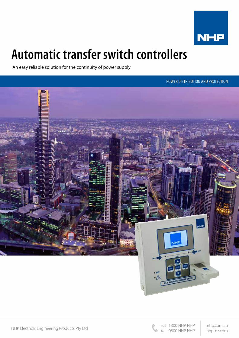
Automatic transfer switch controllers An easy reliable solution for the continuity of power supply
POWER DISTRIBUTION AND PROTECTION
NHP Electrical Engineering Products Pty Ltd1300 NHP NHP0800 NHP NHP
nhp.com.aunhp-nz.comNZ
AUS

2
In today’s industrial and business environments, reliable and continuous power supply is critically fundamental to ensure financial or business losses are not incurred. Modern buildings and industrial complexes have critical loads such as essential lighting, computers and constantly operating industrial equipment and therfore continuity of power is vital for these functions.
NHP’s range of circuit breaker and change over switch technology, Automatic Transfer Switches (ATS), are reliable, durable and versatile to suit any application that requires transferring essential loads and electrical distribution systems from one power source to another.
Our ATS units are available with and without a controller. The controllers provide the intelligence to sense the appropriate conditions for the ATS to initiate a transfer and retransfer to ensure a reliable power supply.
Locally stocked and technically supported within Australia and New Zealand, NHP have both off the shelf and customised ATS solutions to meet almost any technical and cost requirement.
Introduction to automatic transfer switches (ATS)
Main types of NHP transfer switches
• Circuit breaker based
- MCCB
- ACB
• Load break switch based
The NHP ATL 610 controller is designed to control and supervise the automatic or manual transfer of the primary power supply to the secondary power supply in the event of a main source interruption. The functional process allows the device to supervise and manage the changeover between two power supply sources and to control the relative transfer equipment your application requires.
The automatic transfer takes place whenever predefined conditions by the user takes place, such as power supply instability, fluctuations (voltage or frequency), or the need to use the most economical power source.
The ATL610 automatic transfer switch controller from NHP is easy to use, expandable and provides reliable transfer switch control for secure supply of power to your facility. The voltage and frequency measurements are shown on the graphic LCD display with a white backlight ensuring readability. In addition, the LED display provides a clear indication about the network status, along with an easy and intuitive menu navigation.
The NHP ATL 610 controller:Intuitive, reliable and robust solutions
NORMAL STANDBY
TRANSFER SWITCH
LOAD
M/1
Automatic
Normal source failure
Standby source start
Check standby source availability
Transfer the load to standby source
Normal source available
Transfer the load back to normal
source
Standby source stop
Functional process
Transfer switches
3
Introduction to automatic transfer switches (ATS)
Web Based Data Collector (NHP VMUC)
Web Based EMS/BMS Reporting (NHP EM2 Software)
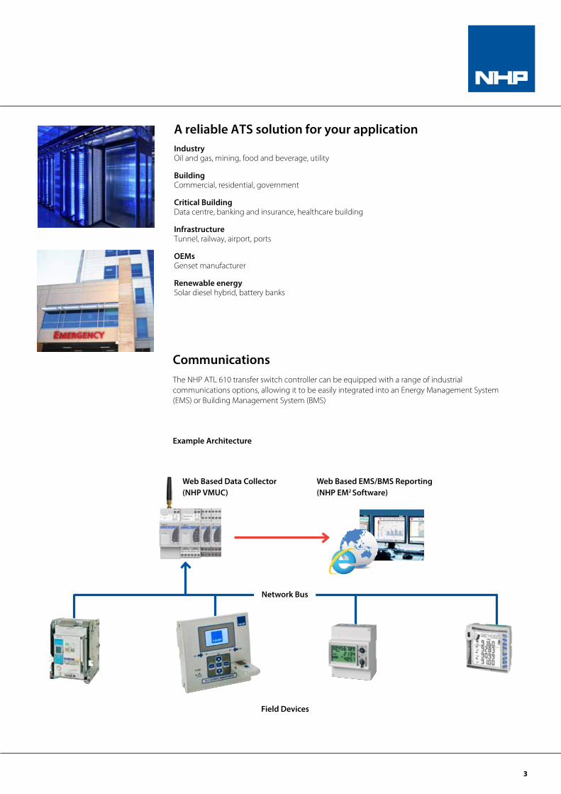
A reliable ATS solution for your application Industry Oil and gas, mining, food and beverage, utility
Building Commercial, residential, government
Critical Building Data centre, banking and insurance, healthcare building
Infrastructure Tunnel, railway, airport, ports
OEMs Genset manufacturer
Renewable energy Solar diesel hybrid, battery banks
CommunicationsThe NHP ATL 610 transfer switch controller can be equipped with a range of industrial communications options, allowing it to be easily integrated into an Energy Management System (EMS) or Building Management System (BMS)
Example Architecture
Field Devices
Network Bus
4
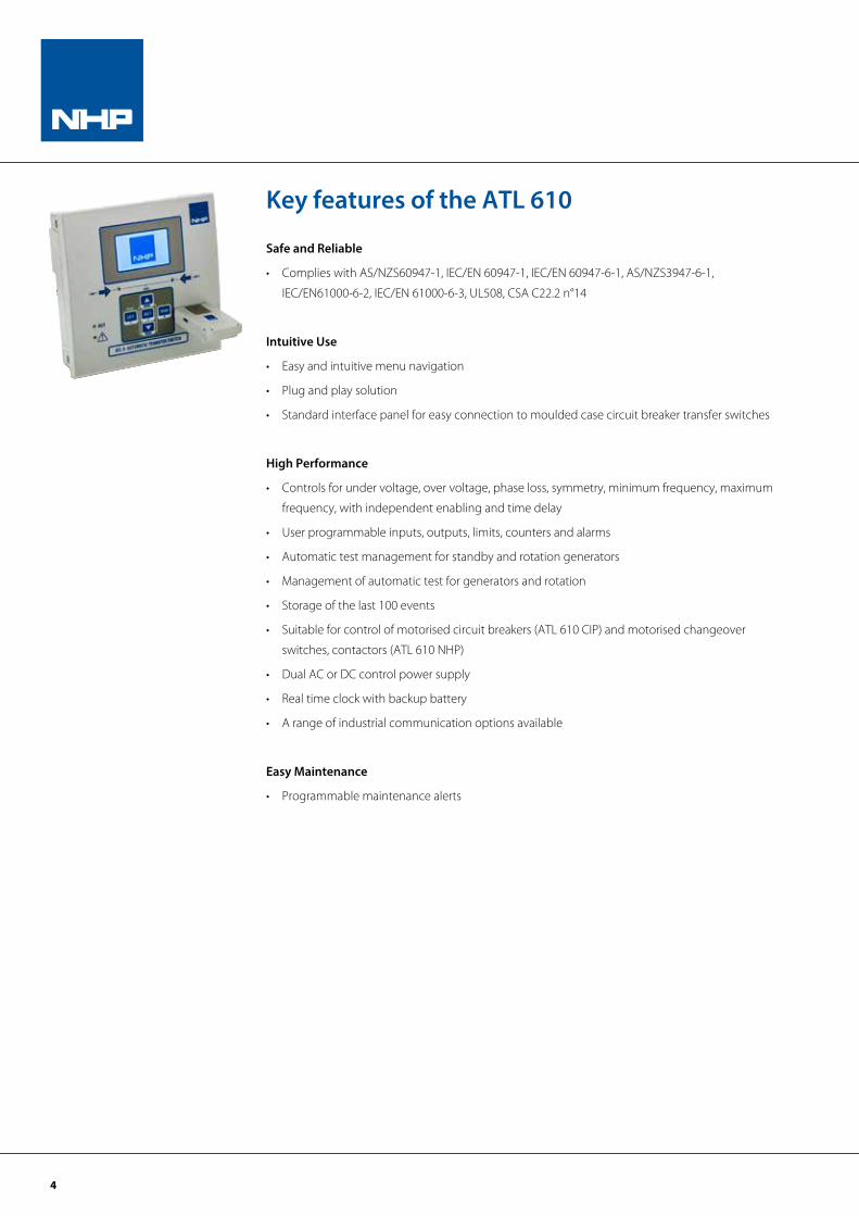
Key features of the ATL 610
Safe and Reliable
• Complies with AS/NZS60947-1, IEC/EN 60947-1, IEC/EN 60947-6-1, AS/NZS3947-6-1,
IEC/EN61000-6-2, IEC/EN 61000-6-3, UL508, CSA C22.2 n°14
Intuitive Use
• Easy and intuitive menu navigation
• Plug and play solution
• Standard interface panel for easy connection to moulded case circuit breaker transfer switches
High Performance
• Controls for under voltage, over voltage, phase loss, symmetry, minimum frequency, maximum
frequency, with independent enabling and time delay
• User programmable inputs, outputs, limits, counters and alarms
• Automatic test management for standby and rotation generators
• Management of automatic test for generators and rotation
• Storage of the last 100 events
• Suitable for control of motorised circuit breakers (ATL 610 CIP) and motorised changeover
switches, contactors (ATL 610 NHP)
• Dual AC or DC control power supply
• Real time clock with backup battery
• A range of industrial communication options available
Easy Maintenance
• Programmable maintenance alerts

5
Benefits of the ATL 610
Switchboard builders
• Consistent sheet metal design with a uniform 144 x 144mm panel cut out size
• Reduced complexity in terms of hardware, spacing and component costs
• Full access to control and auxiliary terminals, reducing installation and wiring time
• Flexible enough to use in new or retrofit builds
• Fast delivery with local stock and technical support from NHP
Consultants
• Complies with AS/NZS60947.6, IEC60947.6 standard
• Simplified logic design - one NHP ATL unit replaces the functionality of many individual relays
• Industrial communication options allowing for BMS integration
• Suits the most common applications such as:
- Utility-to-generator
- Generator-to-generator
- Utility-to-Utility
End users
• Easy to use with an intuitive menu system
• Fast commissioning via the optical port
• Simple ordering with local stock
• Field upgradable I/O and communication modules, reducing initial costs
• Very economical when compared to multi relay / timer ATS control logic systems
• Statistical data available via the LCD or via the industrial communications
• Full technical support from NHP
6
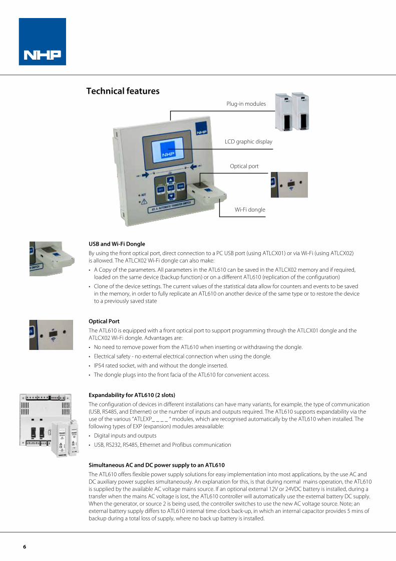
USB and Wi-Fi Dongle
By using the front optical port, direct connection to a PC USB port (using ATLCX01) or via Wi-Fi (using ATLCX02) is allowed. The ATLCX02 Wi-Fi dongle can also make:
• A Copy of the parameters. All parameters in the ATL610 can be saved in the ATLCX02 memory and if required, loaded on the same device (backup function) or on a different ATL610 (replication of the configuration)
• Clone of the device settings. The current values of the statistical data allow for counters and events to be saved in the memory, in order to fully replicate an ATL610 on another device of the same type or to restore the device to a previously saved state
Optical Port
The ATL610 is equipped with a front optical port to support programming through the ATLCX01 dongle and the ATLCX02 Wi-Fi dongle. Advantages are:
• No need to remove power from the ATL610 when inserting or withdrawing the dongle.
• Electrical safety - no external electrical connection when using the dongle.
• IP54 rated socket, with and without the dongle inserted.
• The dongle plugs into the front facia of the ATL610 for convenient access.
Expandability for ATL610 (2 slots)
The configuration of devices in different installations can have many variants, for example, the type of communication (USB, RS485, and Ethernet) or the number of inputs and outputs required. The ATL610 supports expandability via the use of the various “ATLEXP_ _ _ _ “ modules, which are recognised automatically by the ATL610 when installed. The following types of EXP (expansion) modules areavailable:
• Digital inputs and outputs
• USB, RS232, RS485, Ethernet and Profibus communication
Simultaneous AC and DC power supply to an ATL610
The ATL610 offers flexible power supply solutions for easy implementation into most applications, by the use AC and DC auxiliary power supplies simultaneously. An explanation for this, is that during normal mains operation, the ATL610 is supplied by the available AC voltage mains source. If an optional external 12V or 24VDC battery is installed, during a transfer when the mains AC voltage is lost, the ATL610 controller will automatically use the external battery DC supply. When the generator, or source 2 is being used, the controller switches to use the new AC voltage source. Note; an external battery supply differs to ATL610 internal time clock back-up, in which an internal capacitor provides 5 mins of backup during a total loss of supply, where no back up battery is installed.
Plug-in modules
LCD graphic display
Optical port
Wi-Fi dongle
Technical features
7
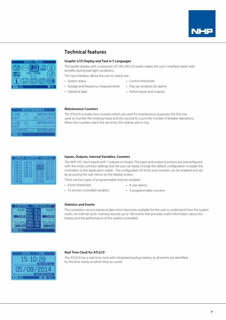
Graphic LCD Display and Text in 5 Languages
The backlit display with a resolution of 128 x 80 LCD pixels makes the user’s interface easier with benefits during bad light conditions.
The new interface allows the user to clearly see:
• System status
• Voltage and frequency measurements
• Statistical data
Maintenance Counters
The ATL610 includes two counters which are used for maintenance purposes; the first one used to monitor the working hours and the second to count the number of breaker operations. When the counters reach the set limits, the relative alarms trip.
Inputs, Outputs, Internal Variables, Counters
The NHP ATL has 6 inputs and 7 outputs on-board. The input and output functions are preconfigured with the most common settings but the user can easily change the default configuration to adapt the controllers to the application needs. The configurable I/O limits and counters can be enabled and set by accessing the sub menus on the display screen.
There are four types of programmable internal variables:
• 4 limit thresholds
• 16 remote controlled variables
Statistics and Events
The controllers record statistical data which becomes available for the user to understand how the system works. An internal cyclic memory records up to 100 events that provides useful information about the history and the performance of the system controlled.
Real Time Clock for ATL610
The ATL610 has a real time clock with integrated backup battery so all events are identified by the time stamp at which they occurred.
Technical features
• Control thresholds
• Pop-up windows for alarms
• Active inputs and outputs
• 4 user alarms
• 4 programmable counters

8
ATL 610
AC POWER
Rated voltage Us 100...240V AC
Operating range 90...264V AC
Frequency 45...66Hz
Immunity time for micro-breaking ≤25ms (110V AC)
≤250ms (220V AC)
Immunity time for micro-breaking
(with EXP expansions)
≤25ms (110V AC)
≤120ms (220V AC)
DC POWER
Rated battery voltage 12-24V DC
Operating range 7.5...33V DC
Maximum power consumption 230 mA at 12V DC and 120 mA at 24V DC
Maximum power consumption/
dissipation2.9W
VOLTMETER INPUTS
Max. rated voltage Ue 480V AC L-L (277V AC L-N) (refer NHP for 690V AC types)
Measuring range 50...576V AC L-L (333V AC L-N)
Frequency range 45...65Hz
Measurement method True root mean square (TRMS)
Measuring input impedance >0.5MW L-N, >1.0MW L-L
Connection method One-phase, two-phase, three-phase line with or without neutral and balanced three-phase
MEASUREMENT ACCURACY
Mains and genset voltage ±0.25% f.s. ±1 digit
DIGITAL INPUTS
Number of inputs 6
Type of input Negative
Input current <8mA
Low input signal ≤2.2V
High input signal ≥3.4V
Input signal delay ≥50ms
CALENDAR CLOCK
Backup reserve power Backup capacitor
Operation without supply voltage 5 min approx.
RELAY OUTPUTS
Number of outputs 7
Configuration
6NO: AC1 - 8A 250V AC; AC15 -1.5A 250V AC; B300
-1 changeover: AC1 - 8A 250V AC,
DC1 - 8A 30V DC;
AC15 - 1.5A 250 VAC,
B300 30V DC1A Auxiliary service
Mechanical / electrical endurance 1x10⁷ / 1x10⁵ operations
Technical data
9
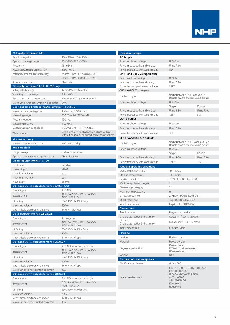
AC Supply: terminals 13,14
Rated voltage Us 100 - 240V~ 110 - 250V=
Operating voltage range 90 - 264V~ 93.5 - 300V=
Frequency 45 - 66Hz
Power consumption/dissipation 3,8W – 9,5VA
Immunity time for microbreakings ≤50ms (110V~ ) ≤250ms (220V~ )
≤25ms (110V~ ) ≤120ms (220V~ )
Recommended fuses F1A (fast)DC supply: terminals 31, 32 (ATL610 only)Battery rated voltage 12 or 24V= indifferently
Operating voltage range 7.5…33V=
Maximum current consumption 230mA at 12V= e 120mA at 24V=
Maximum power consumption/dissipation 2,9W
Line 1 and Line 2 voltage inputs: terminals 1-4 and 5-8
Maximum rated voltage Ue 480V~ L-L (277VAC L-N)
Measuring range 50-576V~ L-L (333V~ L-N)
Frequency range 45-65Hz
Measuring method True RMS
Measuring input impedance > 0.5MΩ L-N > 1,0MΩ L-L
Wiring mode Single-phase, two-phase, three-phase with or without neutral or balanced three-phase system.
Measure accuracy
Mains and generator voltage ±0.25% f.s. ±1digit
Real time clock
Energy storage Back-up capacitors
Operating time without supply voltage About 5 minites
Digital inputs: terminals 15 - 20
Input type Negative
Current input ≤8mA
Input “low” voltage ≤2,2
Input “high” voltage ≥3,4
Input delay ≥50ms
OUT1 and OUT 2 outputs: terminals 9,10 e 11,12
Contact type 2 x 1 NO
Rated current AC1 - 8A 250V~ DC1 - 8A 30V=AC15 -1.5A 250V~
UL Rating B300 30V= 1A Pilot Duty
Max rated voltage 300V~
Mechanical / electrical endurance 1x10⁷ / 1x10⁵ ops
OUT3 output: terminals 22, 23, 24
Contact type 1 changeover
Rated current AC1 - 8A 250V~ DC1 - 8A 30V=AC15 -1.5A 250V~
UL Rating B300 30V= 1A Pilot Duty
Max rated voltage 300V~
Mechanical / electrical endurance 1x10⁷ / 1x10⁵ ops
OUT4 and OUT 5 outputs: terminals 25,26,27
Contact type 2 x 1 NO + contact common
Rated current AC1 - 8A 250V~ DC1 - 8A 30V=AC15 -1.5A 250V~
UL Rating B300 30V= 1A Pilot Duty
Max rated voltage 300V~
Mechanical / electrical endurance 1x10⁷ / 1x10⁵ ops
Maximum current at contact common 10A
OUT6 and OUT 7 outputs: terminals 28,29,30
Contact type 2 x 1 NO + contact common
Rated current AC1 - 8A 250V~ DC1 - 8A 30V=AC15 -1.5A 250V~
UL Rating B300 30V= 1A Pilot Duty
Max rated voltage 300V~
Mechanical / electrical endurance 1x10⁷ / 1x10⁵ ops
Maximum current at contact common 10A
Insulation voltage
AC Supply
Rated insulation voltage Ui 250V~
Rated impulse withstand voltage Uimp 7.3kV
Power frequency withstand voltage 3kV
Line 1 and Line 2 voltage inputsRated insulation voltage Ui 480V~
Rated impulse withstand voltage Uimp 7.3kV
Power frequency withstand voltage 3.8kV
OUT1 and OUT 2 outputs
Insulation type Single between OUT1 and OUT 2Double toward the remaining groups
Rated insulation voltage Ui 250V~
Single Double
Rated impulse withstand voltage Uimp 4.8kV Uimp 7.3kV
Power frequency withstand voltage 1.5kV 3kV
OUT 3 output
Rated insulation voltage Ui 250V~
Rated impulse withstand voltage Uimp 7.3kV
Power frequency withstand voltage 3kV
OUT4-5 and OUT 6-7 outputs
Insulation type Single between OUT4-5 and OUT 6-7Double toward the remaining groups
Rated insulation voltage Ui 250V~
Single Double
Rated impulse withstand voltage Uimp 4.8kV Uimp 7.3kV
Power frequency withstand voltage 1.5kV 3kV
Ambient operating conditions
Operating temperature -30 - +70°C
Storage temperature -30 - +80°C
Relative humidity <80% (IEC/EN 60068-2-78)
Maximum pollution degree 2
Overvoltage category 3
Measurement category III
Climatic sequence Z/ABDM (IEC/EN 60068-2-61)
Shock resistance 15g (IEC/EN 60068-2-27)
Vibration resistance 0.7g (IEC/EN 60068-2-6)
Connections
Terminal type Plug-in / removable
Cable cross section (min… max) 0.2-2.5 mm² (24…12 AWG)UL Rating Cable cross section (min… max) 0,75-2.5 mm² (18…12 AWG)
Tightening torque 0.56 Nm (5 lbin)
Housing
Version Flush mount
Material Polycarbonate
Degree of protectionIP40 on frontIP65 with optional gasketIP20 terminals
Weight 680g
Certifications and compliance
Certifications obtained cULus, EAC
Reference standards
IEC/EN 61010-1, IEC/EN 61000-6-2IEC/ EN 61000-6-3UL508 and CSA C22.2-N°14AS/NZS60947.1 AS/NZS60947.6IEC60947.1IEC60947.6
10
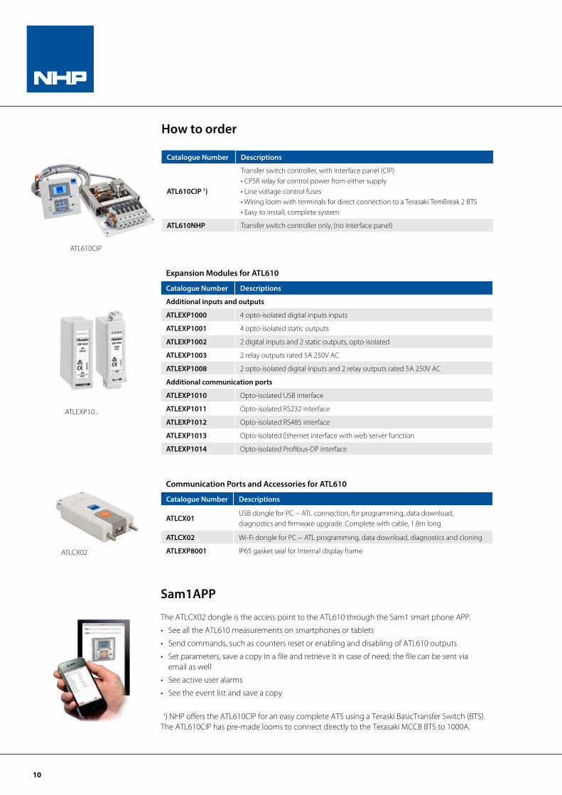
Catalogue Number Descriptions
ATL610CIP 1)
Transfer switch controller, with interface panel (CIP)• CPSR relay for control power from either supply• Line voltage control fuses• Wiring loom with terminals for direct connection to a Terasaki TemBreak 2 BTS• Easy to install, complete system
ATL610NHP Transfer switch controller only, (no interface panel)
How to order
ATL610CIP
Expansion Modules for ATL610
Catalogue Number Descriptions
Additional inputs and outputs
ATLEXP1000 4 opto-isolated digital inputs inputs
ATLEXP1001 4 opto-isolated static outputs
ATLEXP1002 2 digital inputs and 2 static outputs, opto-isolated
ATLEXP1003 2 relay outputs rated 5A 250V AC
ATLEXP1008 2 opto-isolated digital inputs and 2 relay outputs rated 5A 250V AC
Additional communication ports
ATLEXP1010 Opto-isolated USB interface
ATLEXP1011 Opto-isolated RS232 interface
ATLEXP1012 Opto-isolated RS485 interface
ATLEXP1013 Opto-isolated Ethernet interface with web server function
ATLEXP1014 Opto-isolated Profibus-DP interface
ATLCX02
ATLEXP10...
Communication Ports and Accessories for ATL610
Catalogue Number Descriptions
ATLCX01USB dongle for PC − ATL connection, for programming, data download, diagnostics and firmware upgrade. Complete with cable, 1.8m long
ATLCX02 Wi-Fi dongle for PC − ATL programming, data download, diagnostics and cloning
ATLEXP8001 IP65 gasket seal for Internal display frame
Sam1APP
The ATLCX02 dongle is the access point to the ATL610 through the Sam1 smart phone APP.
• See all the ATL610 measurements on smartphones or tablets
• Send commands, such as counters reset or enabling and disabling of ATL610 outputs
• Set parameters, save a copy in a file and retrieve it in case of need; the file can be sent via email as well
• See active user alarms
• See the event list and save a copy
1) NHP offers the ATL610CIP for an easy complete ATS using a Teraski BasicTransfer Switch (BTS). The ATL610CIP has pre-made looms to connect directly to the Terasaki MCCB BTS to 1000A.
11
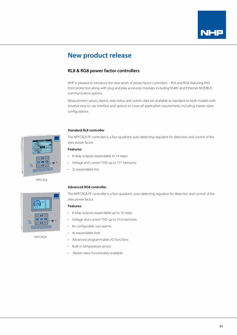
RL8 & RG8 power factor controllers
NHP is pleased to introduce the new series of power factor controllers – RL8 and RG8, featuring IP65 front protection along with plug and play accessory modules including RS485 and Ethernet MODBUS communication options.
Measurement values, alarms, step status and system data are available as standard on both models with intuitive easy to use interface and options to cover all application requirements including master-slave
configurations
Standard RL8 controller
The NPFCRL8 PF controller is a four quadrant, auto-detecting regulator for detection and control of the
sites power factor.
Features:
• 8 relay outputs expandable to 14 steps
• Voltage and current THD up to 15th harmonic
• 2x expandable slot
Advanced RG8 controller
The NPFCRG8 PF controller is a four quadrant, auto-detecting regulator for detection and control of the
sites power factor.
Features:
• 8 relay outputs expandable up to 16 steps
• Voltage and current THD up to 31st harmonic
• 8x configurable user alarms
• 4x expandable slots
• Advanced programmable I/O functions
• Built-in temperature sensor
• Master-slave functionality available
NPFCRG8
NPFCRL8
New product release

NHP Electrical Engineering Products Pty Ltd A.B.N. 84 004 304 812
NATSCC 09/16 © Copyright NHP 2016
For more information, scan to download the NHP eCatalogues App o�ering exclusive video content, catalogues and literature!
For more information, scan to download the NHP eCatalogues App offering exclusive
video content, catalogues and literature
AUSTRALIAnhp.com.au
SALES 1300 NHP NHP
NEW ZEALANDnhp-nz.com
SALES 0800 NHP NHP