An Earth Albedo Model A Mathematical Model for the Radiant ... · NASA Technical Memorandum 104596...
43
NASA Technical Memorandum 104596 An Earth Albedo Model A Mathematical Model for the Radiant Energy Input to an Orbiting Spacecraft Due to the Diffuse Reflectance of Solar Radiation From the Earth Below Thomas W. Flatley and Wendy A. Moore JANUARY 1994 (NASA-TM-IO459&) AN EARTH ALBEDO MODEL: A MATHEMATICAL MODEL FOR THE RADIANT ENERGY INPUT TO AN ORBITING SPACECRAFT DUE TO THE DIFFUSE REFLECTANCE OF SOLAR RADIATION FROM THE EARTH BELOW (NASA) 33 p G3/12 N94-24497 unclas 0202115 https://ntrs.nasa.gov/search.jsp?R=19940020024 2018-07-22T12:49:02+00:00Z
-
Upload
truongdung -
Category
Documents
-
view
217 -
download
1
Transcript of An Earth Albedo Model A Mathematical Model for the Radiant ... · NASA Technical Memorandum 104596...

NASA Technical Memorandum 104596
An Earth Albedo Model
A Mathematical Model for the Radiant
Energy Input to an Orbiting Spacecraft
Due to the Diffuse Reflectance of Solar
Radiation From the Earth Below
Thomas W. Flatley and Wendy A. Moore
JANUARY 1994
(NASA-TM-IO459&) AN EARTH ALBEDO
MODEL: A MATHEMATICAL MODEL FOR THE
RADIANT ENERGY INPUT TO AN ORBITING
SPACECRAFT DUE TO THE DIFFUSE
REFLECTANCE OF SOLAR RADIATION FROM
THE EARTH BELOW (NASA) 33 pG3/12
N94-24497
unclas
0202115
https://ntrs.nasa.gov/search.jsp?R=19940020024 2018-07-22T12:49:02+00:00Z

f_W

NASA Technical Memorandum 104596
An Earth Albedo Model
A Mathematical Model for the Radiant
Energy Input to an Orbiting Spacecraft
Due to the Diffuse Reflectance of Solar
Radiation From the Earth Below
Thomas W. Flatley
Wendy A. Moore
Goddard Space Flight Center
Greenbelt, Maryland
National Aeronautics andSpace Administration
Goddard Space Flight CenterGreenbelt, Maryland
1994

Table of Contents
Introduction ........................................................................................................................... 1
Albedo .................................................................................................................................... 1
Diffuse Reflectance ............................................................................................................. 2
Conditions ............................................................................................................................. 4
Sun Sensors ......................................................................................................................... 5
Calculations .......................................................................................................................... ?
Dividing the Field of View ....................................................................................... 7
Orbital Coordinate Frame ..................................................................................... 12
Calculating _ ....................................................................................................... 13
Calculating 5e ....................................................................................................... 13
Implementing the Algorithm ............................................................................................. 14
Conclusions ........................................................................................................................ 1_5
Table of Variables .............................................................................................................. 17
References .......................................................................................................................... 21
Appendix I : Operational Notes ..................................................................................... 23
Albedo Fortran Program ........................................................................... 27
Appendix I1: Reflectance Data ....................................................................................... 33
iiiPRE,_ PAGE BLANK NOT FILMED

AN EARTH ALBEDO MODEL
Lo.t.m.du.cJ.Lo
Coarse Sun Sensors are often used on spacecraft as part of Attitude
Determination Systems. They function essentially as =Direction Cosine = sensors,with their output approximately proportional to the cosine of the angle betweenthe "boresight = of the sensor and a vector from the spacecraft to the sun. Theirfield of view is approximately hemispherical.
The sensing element is typically a silicon solar cell which produces a currentproportional to the energy flux incident on its surface. Energy can arrive howeverfrom sources other than the sun which lie within the field of view of the sensor.For an Earth-orbiting spacecraft, additional currents could be produced by suchthings as the Moon, sunlight reflected from some part of the spacecraft and/orradiation from portions of the Earth's surface.
This report presents a mathematical model for the Coarse Sun Sensor outputdue to radiation originating from the sunlit portion of the Earth within the sensorfield of view.
Albedo
Solar radiation arriving at the Earth's surface is generally considered to bepartially absorbed, partially specularly reflected and partially diffusely reflected.Local surface characterisics and cloud cover conditions determine the relative
importance of these phenomena.
The energy which is absorbed is eventually re-radiated into space at infraredwavelengths. Solar cells are insensitive to this radiation.
With specular reflection (as commonly occurs with mirrored surfaces) some or allof the incoming solar rays are reflected with the angle of reflection equal to theangle of incidence. Since a spacecraft would receive very little energy from evenan entire Earth which was specularly reflecting this type of reflection is ignored
here.
Here, we consider the sunlit potion of the Earth to be a uniform, diffuse reflectorand will use the word "albedo" in a limited sense, i.e. the albedo constant will betaken to be the ratio of the energy diffusely radiated from a surface to the total
energy incident on the surface.

Diffuse reflectance
Diffuse reflectance is dueto the scattering of theincident light in alldirections. Consider asmall area of the Earth'ssurface, dAe. As thediffuse reflectance
scatters, it forms a 2_steradian solid angle withconstant intensity levelsas shown. As the lighttravels outward, it spreadsout, reducing the intensity.
Incident Light__ 2_ steradian solid
of diffuse reflection
\ .._
/" ./""/\
• "_ / ) / Con_ant intensity levels
__AdA e, piece of sunlit earth in m2
To determine the strengthof the diffuse reflectance at the spacecraft's position, consider the
geometry shown;^
dAe n_
where, _e " unit vector normal to dAe
._ • unit vector from theSunlight Earth to the sun
B • point where ._ intersectsthe Earth's surface
According to Wertz, Fsun, the solar constant in the vicinity of the Earth, is
approximately 1358 wad/m2. The sunlight strikes the Earth with this
intensity at point B. At locations away from this point, the intensity of the
incoming sunlight decreases proportional to cos_, so that the solar flux
reaching any given incremental area is:
Fin = Fsun(ne',S) wa_/m2
This incoming solar flux is partially absorbed and partially reflected. Theamount of light reflected is proportional to the incident light by an albedoconstant, ALB, which depends on the Earth's surface characteristics. (SeeAppendix II.) This model assumes that the albedo constant doesnot vary over the Earth's surface, neglecting the variation ofdiffuse reflectance with geographical features. A good estimate ofthe Earth's annual average albedo constant is 0.3.
Under these assumptions, the amount of solar flux diffusely reflected from
dAe is given by:Fout = ALB(Fin)
= ALB(Fsun)(t_,".s)wa_//m2
2

As the light travels outward, it spreads out, reducing its flux, so only aportion of the diffuse reflectance from dAe actually reaches thespacecraft's position. Consider a hemisphere centered at dAe with radiusD, the distance from dAe to the spacecraft's position.
//
//(
_o " maximum flux at distance D
T-, _ Spacecraft
,,/'_'\--'_ flux at spacecraft:I
O0alb = OOoCOSO watts/m 2
-_ D \\
dAe
total energy over this hemisphere = j"ooo cos (I)(2_D sin (_)Dd(I)$=0
= /tO2(oo watts
By conservation of energy, the total energy over this hemisphere must
equal the energy radiated from dAe. Using this fact, solve for COo:
_D2O0o = Fo=dA e
ALB(Fsun)(fle. _)dA, watt_m 2coo = _D 2
The solid angle subtended by dAe from the spacecraft's point of view, is
given by; _ Spacecraft
dA = dAec°se :"
D 2 dA_ > _e
/
So, the flux at the spacecraft's position is:
03al b = O)0COSO
ALB(Fsun)(_ e •§)dA wattYmeO)al b =

Conditions
The diffuse reflectance from dAe only affects the output current of the sun sensorsif the light reaches the sun sensors. For this to occur, the area, dAe must meet
the following conditions:
1)
2)
Assume a perfectly spherical Earth. The area, dAe, must be on the
sunlit side: l(,s'ne) > 01
^
dAe n_
Sunlight
The area must be in the spacecraft's field of view: I(e_ < (Xm=x)I
^
ne
Spacecraft'sField of View
%
Spacecraft
3) Assume that a Coarse Sun Sensor (CSS) has a conical field of
view with a half angle of A. The reflected light must be in the CSS
field of view: I(_._css) _> cosAJ
Spacecraft
4

Sun Sensors
This algorithm models Coarse Sun Sensors. In general, the Coarse Sun
Sensor's output current, Icss, is proportional to cos_, where _ is the angle
between the CSS boresight and _, the direction of light source:
css light source Icss ¢_ (O)css)COS_
CSS
where, 0)¢= : input flux to CSS
ncss : unit vector normal to the CSS
i_ : unit vector from the CSS to the
light source
Coarse sun sensors typically produce output currents (in the microampere range)when illuminated by direct and/or reflected solar energy. In this
analysis, the output current (Icss) is normalized such that its valuencoming is 1.0 when the sun lies along the boresight of the CSS and there
sunlight is no additional heat input from any other source.
_cslI-* p=o
CSS
In reality,
n c88
cs$
the CSS receives incoming light from Earth as well as from the sun.Consider a small area of the Earth as the sole light source.
j_AI_Ae In this case, the incoming light is albedo rather thanedoSUnlight, SO O,}css=O_alb,the energy flux due to albedo at thespacecraft's position.
If sunlight along the boresight produces a current of Imax, the maximum CSScurrent due to albedo is:
Imax dlalbmax
Fsun 03alb
dlalbmax = Irnax(ALB)(13 e._)dA
5

Since, Icss is proportional to IB, use the maximum values to find an appropriateproportionality constant for dlalb, the CSS output current due to albedo.
dial b = K(COalb)COS_
Substitute the maximum values to find K. Assume that the direction of the
incoming light coincides with the CSS boresight such that _ = 0:
(Im'_)(ALB)(_""')dA:_ K[ ALB(F'u")(_""')dA ]
K = I_ amperesF,_. "'%,
In general, CSS output current is calculated:
I(_ = K(o))cos_
Note that cos_ = (nc_" u); substitution into the general equation, gives theCSScurrent due to albedo from dAe as:
Idla,b= Imax(ALB)(ne'g)(ficss'13)dA=amperes I

_alculations
Consider the Earth as a light source. To calculate dlalb, it is necessary to know _,the direction of the incoming light. At great distances, the Earth may beconsidered a point source; however, at orbital altitudes the curvature of the Earthmust be taken into account. To accomplish this, the Earth is divided intoincremental areas; each reflects light at a slightly different angle. The CSScurrent due to albedo also depends on the strength of the diffuse reflectance,which is a function of ALB and Fin. As previously discussed, it is necessary to
define _e, a unit vector normal to a given area if the Earth, to calculate the
strength of the incoming solar flux.
Earth
-" ........ J CorrespondingdAe
The incremental areas are found by dividing the solid angle subtended by theEarth from the spacecraft's point of view into NA solid angles of equal size (dA),each one corresponding to a piece of the Earth (dAe). Once the areas are
defined, the necessary unit vectors are calculated for each area.
Dividing the Field of View
If the spacecraft is in a circular orbit, the size of the spacecraft'sfield of view remains constant, so that once these areas are defined they
are fixed. If o_max is the angle from the subsatellite point to the horizon for
a spacecraft at altitude, ALTP, above a spherical earth of radius Re, then:
sine, max =R e
(R, + ALTP)
From this, the solid angle subtended by the earth is calculated:

Am=( = 2_(1 - COSO_m=().
Consider a sphere of unit radius centered on the spacecraft, where thesolid angle subtended the Earth defines a spherical segment with asurface area of Amax:
Earth
unit radius sphere
To divide the field of view into NA equal parts, a set of N concentric circles
(i=l,N) is drawn on the spherical segment, where the largest circlecorresponds to the horizon of the Earth. Each circle defines anotherspherical sub-segment and represents the intersection of a cone with the
unit sphere.
Next, each sub-segment must be subdivided into equal solid angles.
To understand how this system of concentric circles may be subdivided
into NA equal areas, consider a flat circle:
,_ashed circle divides dA into 2 equal areas
size of radial division
_ radial line bisects each area
Start with a circle of unit area. Add a circle three times larger. The areaenclosed by the larger circle is nine units. The area between the twocircles is eight units. If this latter area is divided into eight equal parts, the
resultant figure contains nine equal areas.
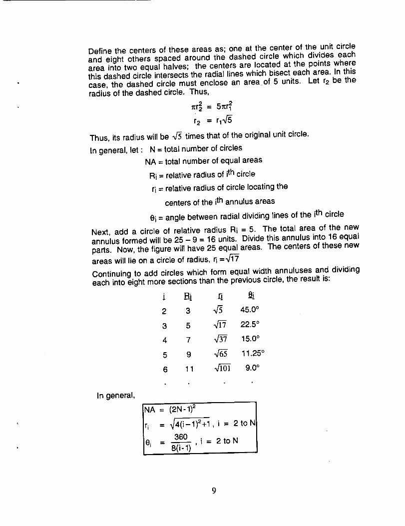
Define the centers of these areas as; one at the center of the unit circleand eight others spaced around the dashed circle which divides eacharea into two equal halves; the centers are located at the points wherethis dashed circle intersects the radial lines which bisect each area. In thiscase, the dashed circle must enclose an area of 5 units. Let r2 be theradius of the dashed circle. Thus,
_:r2 = 5_:rl2
r2 = rl._
Thus, its radius will be V5 times that of the original unit circle.
In general, let : N = total number of circles
NA = total number of equal areas
Ri = relative radius of ith circle
ri = relative radius of circle locating the
centers of the ith annulus areas
0i = angle between radial dividing lines of the ith circle
Next, add a circle of relative radius Ri = 5. The total area of the newannulus formed will be 25 - 9 = 16 units. Divide this annulus into 16 equalparts. Now, the figure will have 25 equal areas. The centers of these new
areas will lie on a circle of radius, ri = 1-_
Continuing to add circles which form equal width annuluses and dividingeach into eight more sections than the previous circle, the result is:
i Ri :i2 3 _/5 45.0 °
3 5 _ 22.5 °
4 7 V'_ 15.0 °
5 9 V-_ 11.25 °
6 1 1 _ 9.0 °
In general,
NA =
r i --
0 i =
(2N - 1)2
_4(i- 1)2+1
360
8(i-1) '
, i = 2toN
2toN
9
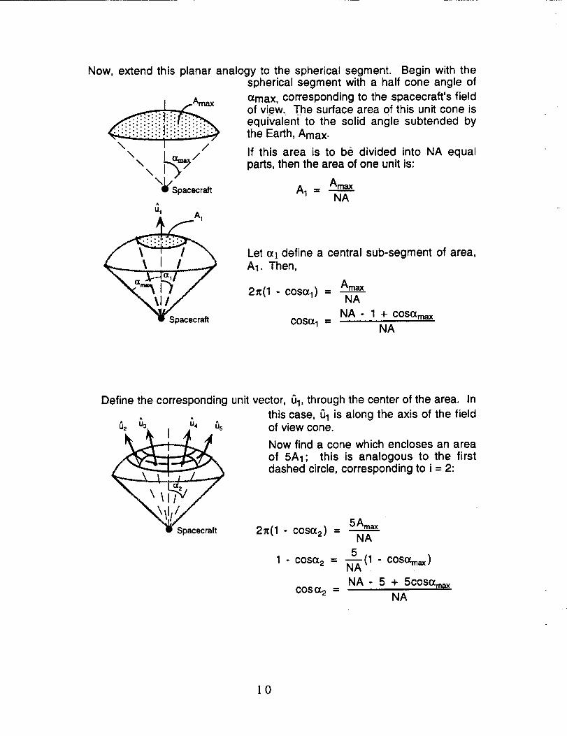
Now, extend this planar analogy to the spherical segment.
\ I /
\\
\;l_Spacecraff
^
u tAI
Begin with thespherical segment with a half cone angle of
¢Xmax, corresponding to the spacecraft's fieldof view. The surface area of this unit cone isequivalent to the solid angle subtended by
the Earth, Amax.
If this area is to be divided into NA equalparts, then the area of one unit is:
A 1 = AmaxNA
Let (x] define a central sub-segment of area,
A1. Then,
Amax2=(1 - cosoh) =
NA
NA - 1 + coS(XrnaxCOS_ 1 =
NA
Define the corresponding unit vector, IJ1, through the center of the area.
^ ^
^ U iI ^
g Spacecraft
In
this case, Ul is along the axis of the fieldof view cone.
Now find a cone which encloses an area
of 5A1; this is analogous to the firstdashed circle, corresponding to i = 2:
5Amax2=(1 - coso_2) =
NA
5
1 - coso_ 2 = N_'(1 - COSO_max)
NA- 5 + 5COS{Xr,_C°S °_2 = NA
l0

^ ^
^ U5 ^ U4 ^u6 _ ul _1 ,"3
u2In addition to 01, define eight more unit vectors
at an angle of 0_2 from the axis of the field ofview cone, equally spaced around the axis in
increments of e2, where 02 360°= ---_--.
These are the first nine unit vectors.
Next, find a cone which encloses an area of 17A1; following the planar
example, the centers of these areas will be evenly spaced around this360° In this case;circle in increments of 03, where e3 = 1--_-"
NA - 17 + 17 cos O%axc°s (z3 = NA
resulting in 16 unit vectors at an angle (7.3from the axis.
In general, there are NA solid angles of equal size. To define theappropriate unit vectors it is necessary to calculate the location of thecenter of each dA.
For the kth solid angle (k=I,NA), the center's coordinates are (_(k,_k),
where Yk is the angle from the axis of the unit field of view cone to the
center of the kth dA and 5k is the radial angle measured counterclockwise
from the 1 axis to the center of the kth dA.
The angular coordinate is calculated as follows:
ri = distance to center of kth area
(constant for each circle)
= _4(i- 1)2 + 1
... _ coordinate of kth area is:
I NA-r 2 + ri2(cos_max)]COS'_k = COSOf.i = NA I for
all areas in the ith circle, where i = 2 to N
1]

To calculate the size of the radial division of the ith circle, let;
,'. t_k coordinate of kth area is I_ki
circle.
M -- number of radial divisions in
ith circle
= 8(i- 1)
ei = size of radial division in ith
circle
360 °
M
where j = 1 to M for the ith
Qrbital Coordinate Frame
The unit vectors are calculated in a 1-2-3 orbital coordinate system, whichmoves with the spacecraft. If the orbit is circular, the vectors are fixed
within this frame, and ne and 0 need only be calculated once, then
transformed to the spacecraft body frame at each time step.
The axes of this 1-2-3 frame are defined as:
= AoXA = (Ax_)xA =
:_= Ao= Axq_=A
where, A • spacecraft unit position vector in earth centered coordinates
• spacecraft velocity unit vector
I:1o • unit orbit normal vector
]2

Calculating Q
In the 1-2-3 coordinate frame, a unit vector from the spacecraft to dAe is:
sinTk cos 5 k1Ok = /sinTk sin(Sk
/
L - COS'Yk 123 frame
Calculating Be
Once 0 has been found for each area, calculate fl,,, the normal to each
area. First, consider the 1-2-3 coordinate frame. In general, any point G in
this coordinate system may be located by 6123, a vector from the Earth's
center to the point, G.
- G
a point on the Earth's surface
n¢
r Du 1 ]LR + Du3
6123 IR + DO
where D is the distance from the
spacecraft to the point G.
To define the normal vector, G must be
3/(DUl)2 + (Du2)2 + (Du3 + R)2 = Re
Solve this quadratic for D:
D --- -au 3 + _(au3) 2 - (a 2- a_)
Choose the smaller value of D, corresponding to G, not G'.
13

Once the appropriate D is calculated, the normal unit vector is:
I [°u1,,ou.,.( n'- .+Ou,jI_ - Spacecraft where
D= -Ru 3 + #(Ru3) 2 - (R 2 - Re2)
Implementin_Q the Al_oorithm
Appendix I contains a copy of the FORTRAN subroutine based on this paper.The table of variables provides a cross reference between the notation in thepaper and the subroutine variables.
In order to optimize the calculations, the subroutine uses the conditions todetermine which areas actually affect a given CSS, then calculates the outputcurrent based on only those areas.
During the first call, the subroutine initializes constants and calculates the unit
vectors, Okand 13ek, for each of the NA areas (k=I,NA). To calculate these
vectors, begin with the first circle (i=1), and place LI1 along the axis of thespacecraft's field of view cone. This corresponds to the vector (0,0,-1) in the
^ I ^
_2-, u3 1 u, _,
"% _..I, /"k :,f x"% ," I', ,"
I Spacecraft
1-2-3 orbital frame.
For the second circle (i=2), calculate (X2
and 02, the size of the angular and radialdivisions for this circle. Then, find the
coordinates ((zk, 8k) of the centers of the
M areas comprising this circle. For each
set of coordinates, calculate Uk, in the1-2-3 orbital frame. Continue this
process, until i3khaS been defined foreach radial division in the second circle,(This corresponds to areas k=2,9). Moveto the next circle and repeat this process
until Lik has been found for all areas, 1
through NA. Once all of the Okvectorsare calculated, the corresponding
14

_ekVectorsare found. By defining the areas based on the spacecraft's field ofview, not only is Condition 2 automatically satisfied, but the smallest possiblearea of the Earth's surface is considered. This ends the initialization process.
At each call, the subroutine calculates the sun unit vector in the 1-2-3 orbital
frame; the position of the sun vector is necessary to test Condition 2. For the Ith
CSS (1=1,P), use the remaining conditions to determine if the albedo from the ktharea effects this CSS. First, determine if the kth area is lit (Condition 1). If so,determine if it falls within this CSS's field of view (Condition 3). Next, check thatthe incoming light is not blocked. (Refer to the Operational Notes in Appendix I fora complete explanation of blockage.) If all of these conditions are met, calculatedlalb from this area. Once dlalb has been calculated for areas 1 through NA,sum these currents to calculate Icss, the total CSS output current due to albedo
for the Ith sun sensor. Repeat this process for each CSS, 1 through P.
Conclusions
This simplified albedo model was developed for use in spacecraft control systemsimulations, specifically, for modeling Coarse Sun Sensors. It is based onseveral approximations. Only diffuse reflectance is included; specularreflectance is neglected. For an elliptical orbit, the unit vectors associated withthe incremental areas should change direction with altitude; instead, thisalgorithm assumes a circular orbit. The albedo constant is set to the annualglobal average for the entire Earth; Appendix II illustrates how the percentage oflight reflected truly varies with geographical features. The Earth is considered aperfect sphere which does not rotate; it was unnecessary to model rotation sincethe albedo constant was not varied.
15

T_ble of Variables
Units are given in parentheses.
The equivalent variables from the albedo subroutine are given inbrackets.
A : transformation matrix from spacecraft body coordinates to the 1-2-3 orbitalframe [A]
Amax : solid angle subtended by the portion of the Earth's surface, visible from thespacecraft (steradian) [AMAX]
A1 : area of central subsegment of unit sphere, define as one unit area, equal tothe size of dA (steradian) [A!]
ALB : ratio of diffuse reflectance to incident light [ALB]
ALTP : altitude of the spacecraft at perigee (km) [ALTP]
B : point where _, intersects the Earth's surface
BLOCK : a Px4 matrix where the first three elements are the components of theunit vector along the axis of the blockage cone in spacecraftbody coordinates, and the fourth element if the half angle ofthe blockage cone in degrees [BLOCK]
BLOCKAGE : flag used to indicate whether the Coarse Sun Sensor's field of viewis partially blocked [BLOCKAGE]
D : distance from the kth dAe to the spacecraft's position (km) [D]
dA : solid angle subtended by the area dAe in the spacecraft's field of view(steradian)
dAe : a piece of the sunlit Earth's surface (m 2)
dlalb : normalized Coarse Sun Sensor output current due to the albedo from asingle dAe (amperes) [DI]
dlalbmax : maximum possible Coarse Sun Sensor output current due to thealbedo from a single dAe (amperes) [IMAX]
Fin : solar flux input to a given dAe (wat_"m2)
Fout : solar flux output from a given dAe (wa_/'m2)
Fsun :solar constant in the vicinity of the Earth (wad/m2)
G : any point in the 1-2-3 orbital coordinate frame
G123 : a vector from the Earth's center to the point, G, in the 1-2-3 orbital frame
I:1o : unit orbit normal vector [HO]
PAGE/(,/ INTENTI0,_JALLYBLA/,!K]? PRai,GCd)iNG PAGE BLANK NOT FILMED

Imax : maximum Coarse Sun Sensor output current. (amperes) [CSSIMAX]
Icss: Coarse Sun Sensor output current (amperes) [ALBICSS]
j : refers to the jth radial area in the ith annulus [J]
K : proportionality constant for normalized Coarse Sun Sensor output current dueto the Earth's albedo [KAPPA]
k : refers to the kth unit area out of NA equal areas [K]
I : refers to the Ith Coarse Sun Sensor of out P Coarse Sun Sensors
M : number of radial division in the ith annulus circle [M]
N : number of concentric circles [N]
NA : number of equal areas Earth is divided into [NA]
r_css : unit vector normal to the Coarse Sun Sensor [NCSS]
ne : outward pointing unit vector normal to dAe [NORM]
P : number of Coarse Sun Sensors [P]
Ri: relative radius of ith circle
I_ : unit vector from the Earth's center to the spacecraft's position [RB]
R" vector from the Earth's center to the spacecraft's position (km)[RMAG = I t]Re : radius of the Earth (Km) [RE]
ri: perpendicular distance from the axis of the spacecraft field of view cone to thecenter of the ith annulus; given in terms of rl [RI]
rl : radius of central circle of unit area
: unit vector from the Earth to the sun [SB]
: in general, a unit vector from the Coarse Sun Sensor to the source of theincoming light; specifically, it is a unit vector from thespacecraft to the kth dAe [U]
: spacecraft velocity unit vector [VB]
oci:angle from the axis of the unit radius spacecraft field of view cone to the centerof the ith annulus
eCrnax: half angle of the cone encompassing the spherical segment; the anglefrom the nadir to the horizon [ALPHAMAX]
_1 : half angle of cone encompassing a central sub-segment of unit area
I_ : angle between 5 and ncss
: half angle of Coarse Sun Sensor's conical field of view [CSSLM = cosA]
18
5k : radial coordinate of the center of the kth dA; the angle measuredcounterclockwise from the 1 axis to the center of the kth dA
_k" angular coordinate of the center of the kth dA; the angle from the axis of theunit radius spacecraft field of view cone to the center of kth
area; it is constant for all areas in the ith circle [CGAMMA
and SGAMMA, cosine and sine of 1_]
O : angle between the kth ne and the spacecraft's position
ei : size of the radial division of the ith circle [THETA]
: variable of integration
C0alb :flux at the spacecraft's position (wad/m2)
00css: flUX input to the CSS (wa_ym2)
O)o: maximum flux at distance D (wa_//m2)
¥: angle between _ and the kth r_e
]9

Earth Albedo and Emitted Radiation. NASA SP-8067. July, 1971.
Wertz, James (ed.). Spacecraft Attitude Determination and Control. D. RiedelPublishing, Co. 1980.
pffli,¢.,rzl3M_iG PAGE BLAr._IK NOT FILMED
PAGE "_-INTENTIONALLYBLANK 2 I

=

Appendix I
23p_.C_t"_'G _'_G,_ _LA_I_- NOT FILMf_

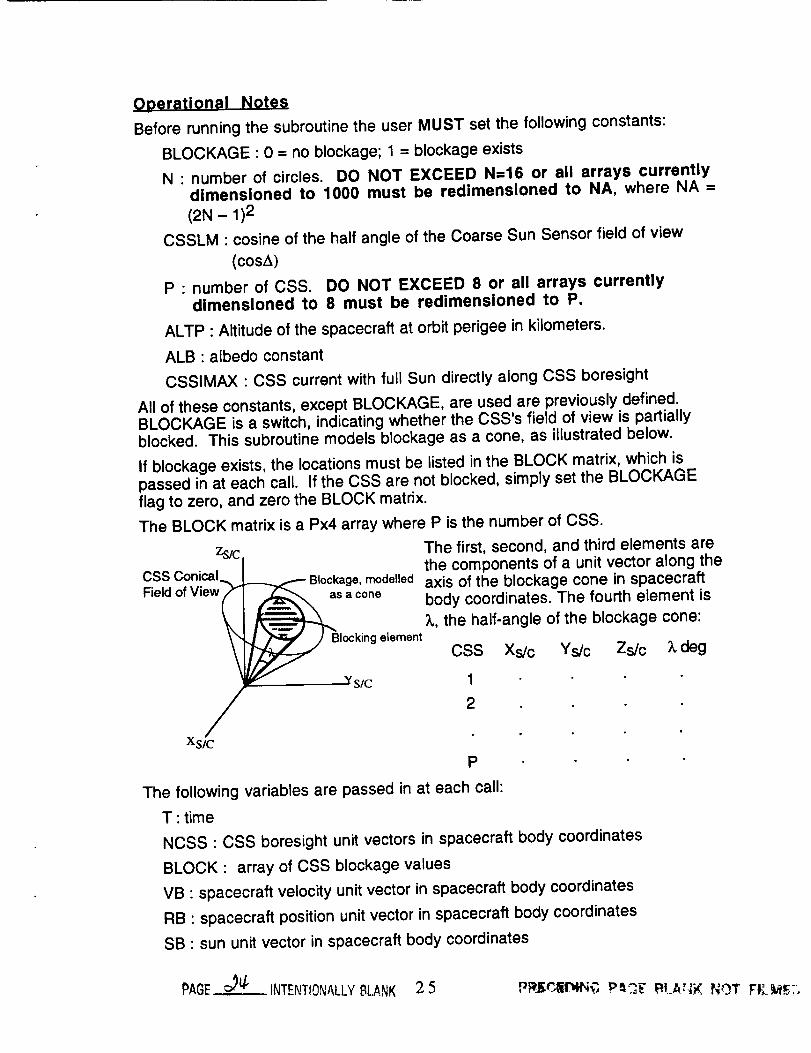
Operational Notes
Before running the subroutine the user MUST set the following constants:
BLOCKAGE : 0 = no blockage; 1 = blockage exists
N : number of circles. DO NOT EXCEED N=16 or all arrays currentlydimensioned to 1000 must be redimensioned to NA, where NA =
(2N- 1)2
CSSLM : cosine of the half angle of the Coarse Sun Sensor field of view
(cosA)P : number of CSS. DO NOT EXCEED 8 or all arrays currently
dimensioned to 8 must be redimensioned to P.
ALTP : Altitude of the spacecraft at orbit perigee in kilometers.
ALB : albedo constant
CSSIMAX : CSS current with full Sun directly along CSS boresight
All of these constants, except BLOCKAGE, are used are previously defined.BLOCKAGE is a switch, indicating whether the CSS's field of view is partiallyblocked. This subroutine models blockage as a cone, as illustrated below.
If blockage exists, the locations must be listed in the BLOCK matrix, which ispassed in at each call. If the CSS are not blocked, simply set the BLOCKAGEflag to zero, and zero the BLOCK matrix.
The BLOCK matrix is a Px4 array where P is the number of CSS.
zs/¢CSS Conical I
Blockage, modelled
Field of View a_B;a conelocking element
CSS Xs/c Ys/c Zs/c X deg
//_ Ys/ 12
Xsic
P
The following variables are passed in at each call:
T : time
NCSS : CSS boresight unit vectors in spacecraft body coordinates
BLOCK : array of CSS blockage values
VB : spacecraft velocity unit vector in spacecraft body coordinates
RB : spacecraft position unit vector in spacecraft body coordinates
SB : sun unit vector in spacecraft body coordinates
The first, second, and third elements arethe components of a unit vector along theaxis of the blockage cone in spacecraftbody coordinates. The fourth element is
;k, the half-angle of the blockage cone:
PAGE _ INTENTIONALLYBLANK 2 5 Pffl£r_liP4_G Pe,CF F_t.AeJ_NOT FI_:__F;.
The albedo subroutine returns
ALBICSS • final CSS currents due to albedo (in same units as CSSIMAX)
26
Albedo Subroutine
SUBROUTINE ALBEDO(T,NCSS,ALBICSS,BLOCK, VB,RB,SB)
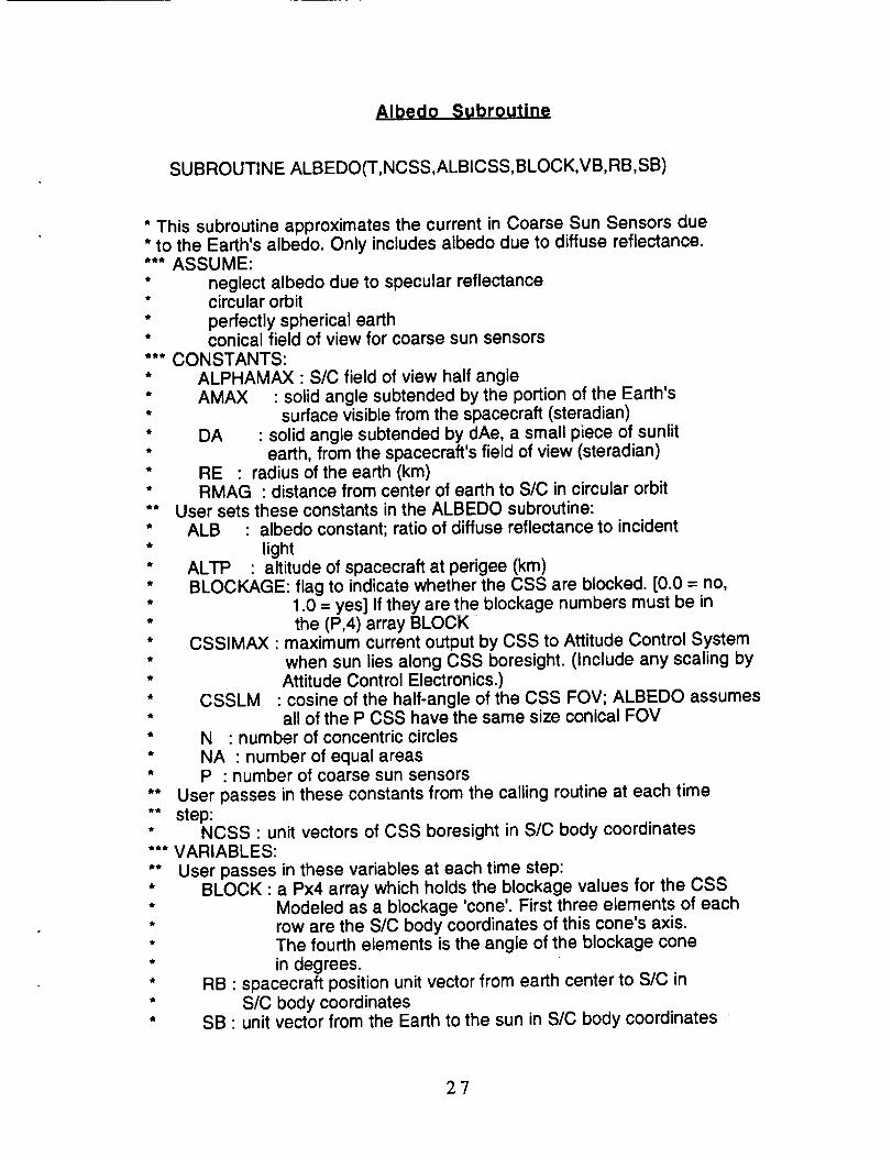
* This subroutine approximates the current in Coarse Sun Sensors due* to the Earth's albedo. Only includes albedo due to diffuse reflectance.*** ASSUME:
* neglect albedo due to specular reflectance* circular orbit
* perfectly spherical earth* conical field of view for coarse sun sensors*** CONSTANTS:* ALPHAMAX : SIC field of view half angle* AMAX : solid angle subtended by the portion of the Earth's* surface visible from the spacecraft (steradian)* DA : solid angle subtended by dAe, a small piece of sunlit* earth, from the spacecraft's field of view (steradian)* RE : radius of the earth (km)* RMAG : distance from center of earth to SIC in circular orbit** User sets these constants in the ALBEDO subroutine:* ALB : albedo constant; ratio of diffuse reflectance to incident
* light* ALTP : altitude of spacecraft at perigee (km)* BLOCKAGE: flag to indicate whether the CSS are blocked. [0.0 = no,* 1.0 = yes] If they are the blockage numbers must be in* the (P,4) array BLOCK* CSSIMAX : maximum current output by CSS to Attitude Control System* when sun lies along CSS boresight. (Include any scaling by* Attitude Control Electronics.)* CSSLM : cosine of the half-angle of the CSS FOV; ALBEDO assumes* all of the P CSS have the same size conical FOV* N : number of concentric circles* NA : number of equal areas* P : number of coarse sun sensors** User passes in these constants from the calling routine at each time** step:* NCSS : unit vectors of CSS boresight in SIC body coordinates*** VARIABLES:** User passes in these variables at each time step:* BLOCK : a Px4 array which holds the blockage values for the CSS* Modeled as a blockage 'cone'. First three elements of each* row are the SIC body coordinates of this cone's axis.* The fourth elements is the angle of the blockage cone
* in degrees.* RB : spacecraft position unit vector from earth center to SIC in* SIC body coordinates* SB : unit vector from the Earth to the sun in SIC body coordinates
27
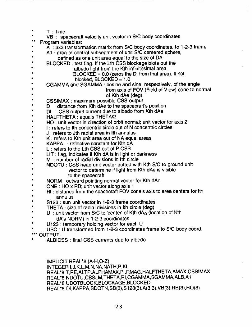
* T- time* VB • spacecraft velocity unit vector in S/C body coordinates** Program variables:* A • 3x3 transformation matrix from SIC body coordinates, to 1-2-3 frame* A1 • area of central subsegment of unit SIC centered sphere,* defined as one unit area equal to the size of DA* BLOCKED • test flag. If the Lth CSS blockage blots out the* albedo light from the Kth infinitesimal area,* BLOCKED = 0.0 (zeros the DI from that area). If not* blocked, BLOCKED = 1.0* CGAMMA and SGAMMA • cosine and sine, respectively, of the angle* from axis of FOV (Field of View) cone to normal* of Kth dAe (deg)* CSSIMAX • maximum possible CSS output* D • distance from Kth dAe to the spacecraft's position* DI • CSS output current due to albedo from Kth dAe* HALFTHETA ' equals THETA/2* HO • unit vector in direction of orbit normal; unit vector for axis 2* I ' refers to Ith concentric circle out of N concentric circles* J • refers to Jth radial area in Ith annulus* K • refers to Kth unit area out of NA equal areas* KAPPA • reflective constant for Kth dA* L • refers to the Lth CSS out of P CSS
* LIT" flag, indicates if Kth dA is in light or darkness* M • number of radial divisions in Ith circle* NDOTU • CSS head unit vector dotted with Kth SIC to ground unit* vector to determine if light from Kth dAe is visible* to the spacecraft* NORM • outward pointing normal vector for Kth dAe* ONE • HO x RB; unit vector along axis 1* RI • distance from the spacecraft FOV cone's axis to area centers for Ith* annulus* $123 • sun unit vector in 1-2-3 frame coordinates.* THETA • size of radial divisions in Ith circle (deg)* U • unit vector from S/C to 'center' of Kth dAe (location of Kth
* dA's NORM) in 1-2-3 coordinates* U123 • temporary holding vector for each U* USC • U transformed from 1-2-3 coordinates frame to SIC body coord.*** OUTPUT:* ALBICSS • final CSS currents due to albedo
IMPLICIT REAL*8 (A-H,O-Z)INTEGER I,J,K,L,M, N,NA,NATH,P,KLREAL*8 T, RE,ALTP,ALPHAMAX,PI,RMAG,HALFTHETA, AMAX,CSSIMAXREAL*8 NDOTU,CSSLM,THETA, Ri,CGAMMA,SGAMMA, ALB,A1REAL*8 U DOTBLOCK, BLOCKAGE,BLOCKEDREAL*8 DI,KAPPA,SDOTN,SB(3),S 123(3),A(3,3),VB(3),RB(3),HO(3)
28
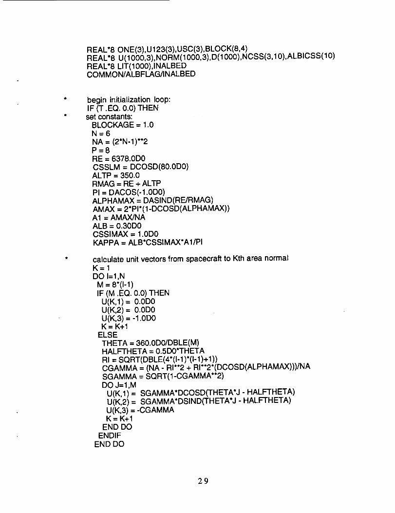
REAL*80NE(3),U 123(3),USC(3),BLOCK(8,4)REAL*8 U(1000,3),NORM(1000,3),D(1000),NCSS(3,10),ALBICSS(10)REAL*8 LIT(1000),INALBEDCOMMON/ALBFLAG/INALBED
begin initialization loop:IF (T .EQ. 0.0) THEN
set constants:BLOCKAGE = 1.0N=6NA = (2*N- 1)**2P=8RE = 6378.0D0CSSLM = DCOSD(80.0D0)ALTP = 350.0RMAG = RE + ALTPPI = DACOS(-1.0D0)ALPHAMAX = DASIND(RE/RMAG)AMAX = 2*PI*(1-DCOSD(ALPHAMAX))A1 = AMAX/NAALB = 0.30D0CSSIMAX = 1.0D0KAPPA = ALB*CSSIMAX*AI/PI
calculate unit vectors from spacecraft to Kth area normalK=IDO I=1,N
a =8"(I-1)IF (M .EQ. 0.0) THEN
U(K,1) = 0.0D0U(K,2) = 0.0D0U(K,3) = -1.0D0K= K+I
ELSETHETA = 360.0D0/DBLE(M)HALFTHETA = 0.5D0*THETARI = SQRT(DBLE(4*(I-1)*(I-1)+I))CGAMMA = (NA - RI**2 + RI**2*(DCOSD(ALPHAMAX)))/NASGAMMA = SQRT(1-CGAMMA**2)DO J=I,M
U(K,1) = SGAMMA*DCOSD(THETA*J - HALFTHETA)U(K,2) = SGAMMA*DSIND(THETA*J- HALFTHETA)U(K,3) = -CGAMMAK = K+I
END DOENDIF
END DO
29

C
C
CC
$
calculate area normalsC = RMAG**2 - RE**2DO K = 1,NA
B = RMAG*U(K,3)D(K) = -B-SQRT(B**2-C)NORM(K,1) = D(K)*U(K,1)/RENORM(K,2) = D(K)*U(K,2)/RENORM(K,3) = (RMAG+D(K)"U (K,3))/RE
ENDDO
ENDIFend initialization loop
AT ALL TIMES:
FIND matrix A to go from s/c body to orbital frame 1-2-3CALL CROSSU(HO,RB,VB)CALL CROSSU(ONE,HO,RB)DO KL=I,3A(1 ,KL) = ONE(KL)A(2,KL) = HO(KL)A(3,KL) = RB(KL)
ENDDO
transform sun unit vector from sic body to 1-2-3CALL TO123(S123,A,SB)
$
Find current in Lth CSS due to albedo of the lit areas:DOL= 1,PALBICSS(L) = 0.0D0
DO K=I,NAdetermine if Kth area is lit:SDOTN =(S 123(1 )*NORM(K, 1)+S123(2)*NORM(K,2)+S123(3)*NORM(K,3))IF (SDOTN .GT. 0.0D0) THENdetermine is the Kth dA is the Lth CSS's FOV:
DO KL=I,3U123(KL) = U(K,KL)
ENDDOCALL TOSC(USC,A,U 123)
N DOTU=(N CSS(1, L)*U SC(1 )+NCSS(2, L)*USC (2)+NCSS(3, L)*U SC (3))IF (NDOTU .GT. CSSLM) THENIf there is CSS blockage, determine if it blocksthe albedo from Kth area:
BLOCKED = 1.0D0IF (BLOCKAGE .EQ. 1.0) THEN
U DOTBLOC K= BLOCK(L, 1)*U SC(1 )+BLOCK(L,2)*U SC(2)+BLOCK(L,3)*USC(3)
30

IF (UDOTBLOCK .GT. DCOSD(BLOCK(L,4))) BLOCKED = 0.0D0ENDIFDI = KAPPA*NDOTU*SDOTN*BLOCKEDALBICSS(L) = ALBICSS(L) + DI
ENDIFENDIF
ENDDOENDDO
RETURNEND
SUBROUTINE CROSSU(C,A,B)C = AxB; normalize C and return a unit vectorINTEGERIREAL*8 C(3),A(3),B(3)C(1) = A(2)*B(3)-A(3)*B(2)C(2) = A(3)*B(1)-A(1)*B(3)C(3) = A(1 )*B(2)-A(2)*B(1 )CMAG = SQRT(C(1)**2+C(2)**2+C(3)**2)DO I=1,3C(I) = C(I)/CMAG
ENDDORETURNEND
SUBROUTINE TO123(V123,A,VSC)transforms a vector from SIC body to 1-2-3 orbital frameINTEGER I,J,KREAL*8 V123(3),A(3,3),VSC(3)DO J=1,3DO I=1,3V123(J) = V123(J) + A(J,I)*VSC(I)ENDDO
ENDDOVMAG = SQRT(V123(1)**2+V 123(2)*'2+V123(3)*'2)DO K= 1,3
V123(K) = V123(K)NMAGENDDORETURNEND
SUBROUTINE TOSC(VSC,A,V123)transforms a vectors from orbital frame 1-2-3 to S/C bodyINTEGER I,J,KREAL*8 V123(3),A(3,3),VSC(3)DO I=1,3DO J=1,3
3]

VSC(I) = VSC(I) + A(J,I)*V123(J)ENDDOENDDOVMAG = SQRT(VSC(1)**2+VSC(2)**2+VSC(3)**2)DO K=1,3
VSC(K) = VSC(K)NMAGENDDORETURNEND
32

Appendix II
33


PA(3_[_._z/__ INTENTtONAL[.'/E_ ,4,_;_35
PRECEO4NG PAGE BLANK NOT FI4.MED
i
Form ApprovedREPORT DOCUMENTATION PAGE OMBNo. 0704-0188
Pubic report ng burden fo_'this collection o' information is estimated to average I hour per response, including the time for reviewing !.=Ituctionl. l,lmrching exil1!ng data _._urf_h=;
g=h.,i.g.ndma_.,.i.i._th.d.t=na.d.d.._dcom.,._i.g.._,..,.--,.gth._,,._,ono,..,o.m=,on.S:.d_m.,..t.r.p,_,.gth,.bu_..p-_,o,..yoL..,_...,.oncollection of information, ;ncluding ,,uggeslion$ for reducing th,s burden, to Washmglon Headquarters Serve°s. u,reclot_° ror ,.n,ormat _K).n.UperaTm.ns.nno nel:)O_*,. ,_,:K_. I
Davis Highway, Suite 1204, Arlington,-_'A 22202-4302, and to the Ofhco of Management and Budget, Paperwork Reduction Project (07_ ols'), wasmnglon, u,,. .....
1. AGENCY USE ONLY (Leave blank) 2, REPORT DATE 3. REPORT TYPE AND DATES COVEREDJanuary 1994 Reference Publication
ii
4. TITLE AND SUBTITLE 5. FUNDING NUMBERS
An Earth Albedo Model - A Mathematical Model fo_r the Rad_ntEnere, y Input to an Orbiting Spacecraft Due to thi_ Diffuse Re]tectanceof Soli_r Radiation From t/ze _arth Below
7106. AUTHOR(S)
Thomas W. Flafley and Wendy A. Moore
7. PERFORMING ORGANIZATION NAME(S) AND ADDRESS (ES)
Goddard Space Flight Center
Greenbelt, Maryland 20771
9. SPONSORING / MONITORING ADGENCY NAME(B) AND ADDRESS'(ES)
National Aeronautics and Space Administration
Washington, DC 20546-0001
8. PEFORMING ORGANIZATIONREPORT NUMBER
94B00034
10. SPONSORING / MONITCn:,%'GADGENCY REPORT NUMBER
NASA TM-104596
11. SUPPLEMENTARYNOTES
Flatley and Moore: Goddard Space Flight Center, Greenbelt, Maryland
12a. DISTRIBUTION / AVAILABlUTY STATMENT
Unclassified - Unlimited
Subject Category 12
12b. DISTRIBUTION CODE
13. ABSTRACT (Maximum 200 words)
Past missions have shown that the Earth's albedo can have a significant effect on the sun sensors used
for spacecraft attitude control information. In response to this concern, an algorithm was developed to
simulate this phenomenon, consisting of two parts, the physical model of albedo and its effect on the
sun sensors. This paper contains the theoretical development of this model, practical operational notes,
and its implementation in a FORTRAN subroutine.
14. SUBJECT TERMS
Albedo; Reflectance; Sun Sensors; Solar Flux; Solar Radiation; Reflection;
Spacecraft Sensors; Light; Course Sun Sensors
17. SECURITY CLASSIFICATION 18. SECURITY CLASSIFICATIONOF REPORT OF THIS PAGE
Unclassified Unclassified-- . • ii -- -
NSN 7540-01-280-5500 ....
19. SECURITY CLASSIFICATIONOF ABSTRACT
Unclassified
15. NUMBER OF PAGES44
16. PRICE CODE
20. UMITATION OF A_iP, ACT
UL
Standard Form 298 (Rev. 2-89)Preecti:,ed by ANSI Std. Z39.18
298-102

National Aeronautics and
Space AdministrationCode J13"Washington, D.C.20546-0001
Official Business
Penalty for Private Use, $300
SPECIAL FOURTH-CLASS RATE
POSTAGE & FEES PAID
NASA
PERMIT No. G27
POSTMASTER: If Undeliverabk3 (Section 158,
Postal Manual) Do Not Return