Geostrophic Adjustment in an Axisymmetric Vortex - Atmospheric
Original scientific paperUDC 551.556.3
An atmospheric gravitational vortex as a flow object:
improvement of the three-layer model
Sandro Ni`eti}
Department of Thermodynamics, Thermotechnics and Heat Engines, Faculty of Electrical Engi-neering, Mechanical Engineering and Naval Architecture, University of Split
Received 26 May 2009, in final form 24 November 2009
An improved physical and analytical three-layer model of gravitationalvortex columns (GVCs) for solar chimney power plants is developed in this pa-per. In essence, this model represents a further improvement and upgrade ofthe three-layer model proposed in Nini} et al. (2009). The improvements ofthe three-layer model deal with internal friction, variable vertical velocity (byheight) in the central GVC spiraling upward flow, and variable angular mo-mentum of the downdraft shell. A numerical solution of the improved modelis given as a characteristic case and is compared to the elementary GVCmodel. The results show that the introduced improvements are important pa-rameters for further analysis of gravitational vortex columns.
Keywords: Gravitational vortex, solar chimney, numerical modelling
1. Introduction
The concept of the gravitational vortex column (GVC) for solar chimneypower plants was proposed in Nini} (2006). An elementary model of a station-ary GVC was developed by Nini} et al. (2009). The solar chimney power plant(SC) was originally proposed by J. Schlaich in 1968, and represents the basisfor the further extension of the GVC concept. Solar chimneys have been exten-sively studied; see, for example, Haff et al. (1983), Haff (1984), Padki andSherif (1989), Schlaich (1995), Bernardes et al. (2003), Backström von T.W.(2006), Bilgen (2005) and Ni`eti} et al. (2007, 2008 and 2009). A detailed liter-ature review of this field was given in Bernardes et al. (2003).
The idea of using an atmospheric gravitational vortex as a flow object isnot a new one. It was originally presented in Dessoliers (1913). Dessens (1962,1969) performed an experiment that proved such an idea in principle. Michaud(1975) proposed a ªvortex power station” and also developed his idea in laterpapers, including Michaud (1995, 1999). The same author also performed asimple experiment as a validation of his assumptions. These papers demon-strated the potential for the technical utilization of the working availability of
GEOFIZIKA VOL. 27 2010

warm moist air (i.e., the technically feasible part). Namely, the technically fea-sible part of working availability is equivalent to the work of the buoyancyforce affecting 1 kg of air that has left the collector. Michaud (1995), Michaud(1996), Nini} (2006) and Nini} at al. (2006) dealt with the magnitude of warmmoist air’s working availability in the atmosphere.
Furthermore, Michaud (1975) and Nini} and Ni`eti} (2007) considered thepossibility of the technical utilization and the controlled use of a vortex forcapturing the working availability in the atmosphere (i.e., for the productionof mechanical work). This mechanical work, produced from solar energy, couldbe obtained by ground level turbines.
In the previously mentioned papers, a vital part of the plant (the part thattransforms solar energy into mechanical work) is the vortex flow structure.Nini} and Ni`eti} (2007) showed that in a solar chimney power plant with ashort diffuser, the air is heated in the solar collector as in the SC power plant.Thus, a relatively tall concrete chimney could be replaced with a short one.The second concept proposed by Michaud (1995, 2005) is almost analogous tothe previously mentioned concept. The difference between these two solutionsis in the process of air heating. In Michaud’s concept, the air is heated bywaste industrial heat, while in Nini}’s concept the air is heated by utilizationof energy from the solar collector. A detailed overview of Michaud’s conceptwas given in Nini} et al. (2009).
However, in Michaud (1995, 2005) and Nini} (2006), detailed physical andanalytical formulations of the vortex stream structure were not elaborated, al-though they did appear in Nini} et al. (2009). This paper deals with a station-ary vortex flow structure (as a part of the plant), which is called a GVC. For asimplified physical and analytical ªthree-layer” model of GVCs, a numericalsimulation algorithm (GVC-simulator) has also been developed.
Hence, the objective of this paper is to further improve the elementarythree-layer model of GVCs first proposed in Nini} et al. (2009). The introducedimprovements are related to:
– variable vertical velocity in the central GVC updraft flow;– the influence of the internal friction work;– the reduction of the downdraft shell angular momentum.These improvements will be introduced in the improved three-layer ana-
lytical model. Impact parameter analysis will also be performed in order to de-termine how the improvements affect the GVC flow structure.
2. Physical characteristics of the improved GVC model
As in the elementary GVC model (Nini} et al., 2009), we start from the as-sumption of stationary updraft airflow at the exit of a short chimney posi-tioned over the turbines. The updraft has a spiraling upward flow. As a conse-quence, the pressure inside the flow structure is lower than the atmospheric
2 SANDRO NI@ETI]: AN ATMOSPHERIC GRAVITATIONAL VORTEX ...

pressure at the same height. The structure of the elementary three-layer sta-tionary model is illustrated in Fig. 1.
According to Fig. 1, the flow structure of the GVC consists of three charac-teristic sections: B, C, and E. Through the first GVC section (R1(z) > R(z) > 0),the updraft (Fig. 1, airflow B) has a spiraling upward flow. According to theassumptions, this airflow is rotating as a solid body with respect to the ªfreevortex” law in Rankine’s terminology. This assumption was validated by fieldobservations of natural vortex structures in Bluestein (2005). The second sec-tion of the GVC is annular rising flow C (R2(z) > R(z) > R1(z)), which is con-centric with the central one (airflow B). Both airflows B and C originate fromthe equilibrium air collector adiabat (all air states inside the sections will beon this adiabat). The third GVC section is a characteristic downdraft shell,modeled as a cooled descending airflow, E.
GEOFIZIKA, VOL. 27, NO. 1, 2010, 1–20 3
Figure 1. A simplified three-layer physical model of the GVC stationary vortex column, Nini} etal. (2009).

In this paper, we did not analyze the structure of the downdraft shell; it ismodeled as a black box. However, in the improved model we impose a parame-ter (the downdraft shell characteristic Pk(z)) that characterizes this unknowndowndraft shell structure.
The reason for supplementing the first proposed two-cell model with thethree-layer model was explained in detail in Nini} et al. (2009). In the samepaper, according to thermodynamic analysis of the two-cell model, it was con-cluded that the two-cell model cannot be the basis for realistic functioningGVC devices if sufficient heat rejection is not ensured. Specifically, the pres-sure gap, pa(0) – p2(0), can only be bridged with sufficient heat rejection. Thisconclusion is the most important one because it ensures a sufficient quantityof turbine work. There are two possible means of heat rejection. The first is bythe downdraft shell mechanism (cooled air downdraft, marked E in Fig. 1).The second way is provided by a weakly forced central downdraft of cold air inthe central section of the GVC. The variant with the downdraft shell mecha-nism is analyzed in this paper.
A schematic overview of the profiles for three axially symmetric layersthat are characterized by the pressure p(z), circular velocity wc(z), vertical ve-locity wz(z), and by radii R1(z), R2(z), and R3(z) are also shown in Fig. 1.
In Nini} et al. (2009), the radial loss of angular momentum in the direc-tion of the static atmosphere was neglected (the reason for this was discussedin section 5.0 of the same paper). In this improved model, radial loss of thedowndraft shell angular momentum is reduced by a specified factor. Thismeans that the possibility of radial loss of angular momentum at the down-draft shell periphery (because of side contact with standard atmosphere, asper NOAA, 1976) has been taken into account.
Internal friction is also taken into account with the unused part of work-ing availability at the top of the GVC (Decoll tech
net ) that was purposely left out. Inthis paper, the structure of the expression for the internal friction work, Dwfr,was not worked out but the quantity of the unused part of the availability atthe top of the GVC (which has been ªreserved” for internal friction work) wasvaried in a simplified energy Eq. (1)1. By doing this, the influence of internalfriction on the physical values of the GVC is ensured.
–vDp = Dep + Dek + Dwfr (1)
The starting assumptions, boundary conditions, and other physical cir-cumstances are identical to those discussed for the elementary model in Nini}et al. (2009) (see sections 2 and 6). Thermodynamic validation of the proposedphysical three-layer model with a downdraft annular shell was also provided
4 SANDRO NI@ETI]: AN ATMOSPHERIC GRAVITATIONAL VORTEX ...
1 Eq. (1) is written for the stream line along the annular updraft flow.

in the same paper (in section 4.2). Thus, the improved three-layer model isalso validated by relying on the conclusions that were derived for the elemen-tary three-layer model.
3. Analytical formulation
As in the case of the elementary GVC model, relations based on generalprinciples of conservation of mass, momentum, and angular momentum, andthe First Law of Thermodynamics where used.
The introduced improvements will be analytically formulated in the fol-lowing section of this paper.
3.1. Variable vertical velocity at the central GVC section
The first improvement is related to the variability of velocity with heightat the central GVC section, 0 1w zz ( ). This vertical velocity is uniform along theradius at any distance from the ground in the section R1(z) > R(z) > 0. If weapply the First Law of Thermodynamics for a specific streamline in the GVCaxis (for two different thermodynamic observers, Ni`eti} (2009)) we can deter-mine the vertical velocity, w0(z). In the first approximation, we assumed thatthe vertical velocity of the air in the GVC axis is approximately equal to theaverage vertical velocity at the central GVC section, i.e. w0(z) ≅ 0 1w zz ( ). TheFirst law of Thermodynamics, in its general form, is:
–n(z)dp(z) = dep + dek + dwfr = g dz + wz(z)dwz(z) + wc(z)dwc(z) + dwfr, (2)
where ep is the specific potential energy, ek is the specific kinetic energy, wz(z)is the vertical velocity, wc(z) is the circular velocity and wfr is the internal fric-tion work. Hence, if we apply Eq. (2) for a streamline in the GVC axis, it fol-lows that:
–n(z)dp0(z) = g dz + wz0(z)dwz0(z). (3)
Eq. (3) with respect to Eq. (2) does not have the term related to internalfriction work (because the friction is not present in the GVC axis), and theterm for circular velocity is also eliminated (as a consequence of the Rankinefree vortex law). By integration of Eq. (3), the distribution of vertical velocitywith height on the central section of the GVC can be determined. After deter-mination of the vertical velocity wz0(z), a correction of the pressure in the GVCaxis must be done. Namely, the pressure in the GVC axis, p0(z), must be lowerdue to the amount of kinetic energy expressed in the vertical velocity wz0(z).Hence it follows that:
dp0(z) = r0(z)wz0(z)dwz0, (4)
where r0(z) is the average density of air in the GVC axis from the equilibriumair collector adiabat (determined for specified tcoll and jcoll). Therefore, in each
GEOFIZIKA, VOL. 27, NO. 1, 2010, 1–20 5

numerical step, the vertical velocity of air in the GVC axis (i.e., according tothe approximation of its average value 0 1w zz ( )) can be calculated from Eq. (3).After that, the pressure correction must be done according to Eq. (4).
In this procedure, the variation of vertical velocity with height in the GVCaxis is also taken into account (which was not the case in the elementary GVCmodel, where this vertical velocity was assumed to be constant and negligible).
3.2. Quantity of internal friction work in the GVC flow structure
In this improved GVC model, internal friction work is treated in the zone ofthe annular updraft shell, R2(z) > R(z) > R1(z), using the characteristic stream-line on the radius R1(z). The amount of internal friction work dwtr is ensured inEq. (2). Hence, Eq. (2) applied to the streamline on the radius R1(z) is:
–n(z)dp1(z) = gdz + wc1(z)dwc(z) + wz1(z)dwz(z) + dwfr. (5)
In section 5 of Nini} et al. (2009), the influence of internal friction workwas analyzed in detail. In the same paper (see Fig. 10), the characteristicMollier h–s diagram of the process in the GVC with a Brayton cycle was alsoshown. In this analysis, a certain amount of the unused part of the availabilityDecolltech
net has been purposely left out as a ªreserve” for the internal frictionwork Dwfr. According to Fig. 10 from Nini} et al. (2009), for certain circum-stances the analytical reserve for internal friction work can be obtained as:
wfr_re = h12+ – h02 , (6)
where wfr_re ≡Decolltechnet .
Hence, the available reserve for the internal friction work is calculated asan enthalpy difference of characteristic air states at the maximum availableGVC height (the troposphere layer at zmax). In this improved model, the distri-bution of internal friction work is assumed to be linear (i.e., it is distributedlinearly along the streamline on the radius R1(z) from the ground level tozmax). Hence, one part of the internal friction work is present in each numeri-cal step depending on the value of the internal friction factor kfr. In general,the internal friction work reduces the available part of the working availabil-ity Decolltech
net .The quantity of internal friction work (in each height step) Dwfr(z) is de-
fined by:
Dwfr(z) = wfr_m · Dz · kfr, (7)
where the internal friction work per meter of GVC height is:
wfr_m =w
z z
fr re
d
_
max−D, (8)
6 SANDRO NI@ETI]: AN ATMOSPHERIC GRAVITATIONAL VORTEX ...

with the requirement that:
Dw z wfr fr rez
( ) _≤∑ . (9)
The internal friction factor kfr is introduced in Eq. (7). The reason for thislies in the possibility of investigating the magnitude of the effects of the inter-nal friction work, kfr, on the GVC’s physical parameters. The degree of inter-nal friction work utilization is introduced via the factor. mfr. It is defined as:
mfr =Dw z
w
frz
fr re
( )
_
∑≤1, (10)
where by using the factor mfr the amount of extracted internal friction workcan be determined.
With this approach, the internal friction work is taken into account with-out elaboration of its structure.
3.3. Radial loss of downdraft shell angular momentum
In this improved model, radial loss of angular momentum is taken into ac-count in a simplified way. In Nini} et al. (2009), the reasons for neglecting ra-dial angular momentum dissipation were specified. However, it was alsopointed out that the possibility of radial loss of angular momentum at the pe-riphery of the downdraft shell exists (because of side contact with the atmo-sphere). So, in this improved and simplified model, radial loss of downdraftshell angular momentum is included using the parameter f. In this case, thedowndraft shell angular momentum is:
ak = f · a, (11)
where the parameter f represents the factor for reduction of the downdraftshell angular momentum. Thus, the downdraft shell angular momentum is al-ways lower than (or equal to) the initial angular momentum (a � ak).
3.4. Closed system of equations for the improved GVC model
In the closed system of equations for the elementary GVC model (see sec-tion 7.0 in Nini} et al., 2009), there were six unknown functions of height. Inthis improved model there is an additional differential equation, which is re-lated to the variable vertical velocity at the central section of the GVC. Otherimprovements (internal friction and downdraft shell angular momentum) arealso taken into account as extensions of the elementary GVC model’s systemof equations. Hence, with the known boundary conditions (which are analo-gous to those used in the elementary GVC model in Nini} et al., 2009) andwith the introduced improvements, the closed differential equation system(with seven equations) can be formulated as follows:
GEOFIZIKA, VOL. 27, NO. 1, 2010, 1–20 7
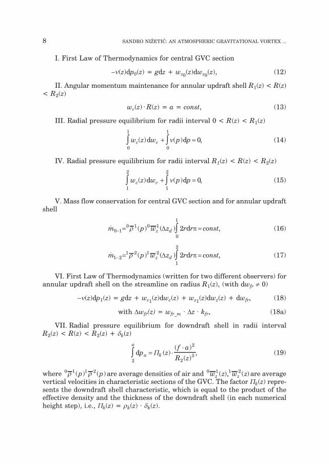
I. First Law of Thermodynamics for central GVC section
–n(z)dp0(z) = gdz + wz0(z)dwz0(z), (12)
II. Angular momentum maintenance for annular updraft shell R1(z) < R(z)< R2(z)
wc(z) · R(z) = a = const, (13)
III. Radial pressure equilibrium for radii interval 0 < R(z) < R1(z)
w z w p pc c( ) ( )d d0
1
0
1
0∫ ∫+ =n , (14)
IV. Radial pressure equilibrium for radii interval R1(z) < R(z) < R2(z)
w z w p pc c( ) ( )d d1
2
1
2
0∫ ∫+ =n , (15)
V. Mass flow conservation for central GVC section and for annular updraftshell
� ( ) ( )m p w z r r constz d0 10 1 0 1
0
1
2− = =∫r D pd , (16)
� ( ) ( )m p w z r r constz d1 21 2 1 2
1
2
2− = =∫r D pd , (17)
VI. First Law of Thermodynamics (written for two different observers) forannular updraft shell on the streamline on radius R1(z), (with dwfr ¹ 0)
–n(z)dp1(z) = gdz + wc1(z)dwc(z) + wz1(z)dwz(z) + dwfr, (18)
with Dwfr(z) = wfr_m · Dz · kfr, (18a)
VII. Radial pressure equilibrium for downdraft shell in radii intervalR2(z) < R(z) < R2(z) + dk(z)
dp zf a
R za
a
k2
2
23∫ = ⋅
⋅P ( )
( )
( ), (19)
where 0 1 1 2r r( ) ( )p p are average densities of air and 0 1 1 2w z w zz z( ), ( ) are averagevertical velocities in characteristic sections of the GVC. The factor Pk(z) repre-sents the downdraft shell characteristic, which is equal to the product of theeffective density and the thickness of the downdraft shell (in each numericalheight step), i.e., Pk(z) = rk(z) · dk(z).
8 SANDRO NI@ETI]: AN ATMOSPHERIC GRAVITATIONAL VORTEX ...

GEOFIZIKA, VOL. 27, NO. 1, 2010, 1–20 9
Figure 2. Flowchart for improved GVC simplified model.

If the above system of equations is solved, the physical values of state (forthe improved GVC model) can be obtained for an arbitrary height step. In theremainder of this paper, the algorithm for the two-dimensional improved GVCmodel is given together with a characteristic numerical solution.
4. An algorithm and characteristic numerical solution
4.1. Flowchart for numerical simulation algorithm
For the purpose of this analysis, a computer simulation program has alsobeen developed. A flowchart of the improved GVC simulation algorithm isshown in Fig. 2.
The start of the program considers the state of air in front of the turbines(tcoll and jcoll). Then, the program computes the equilibrium air collectoradiabat (i.e., the calculation of air properties by height, r(z), p(z) and the calcu-lation of pressure in the GVC axis). The program then proceeds with the defi-nition of the starting radius (at the level of the short chimney outlet) R1(Dzd)and continues with the calculation of the GVC values of state in the first nu-merical step (i = 1). In the same numerical step, the turbine parameters (totalturbine power and heat to work efficiency) are also calculated. Then the pro-gram checks the satisfactions of two specific conditions, h0tot
< h0tot(this con-
dition ensures working availability for internal friction work) and Dp2–a > 0(fulfillment of downdraft shell radial pressure equilibrium). If the conditionsare satisfied, the internal friction parameters wfr_re, wfr_m and mfr are calcu-lated. The program continues to the second numerical step (i = 2), where (ac-cording to the presented and improved analytical GVC model) values of state(properties) in the GVC are calculated for an arbitrary height (if theabove-mentioned specified conditions are fulfilled). The program stops whenthe troposphere height level (zmax) is reached.
4.2. Characteristic numerical solution
To calculate the physical properties of the improved GVC model, it is nec-essary to define the boundary conditions at the height level of the short chim-ney outlet Dzd. Hence, the boundary conditions are:
– total mass flow rate of air: ma = 9 500 [kg/s],– angular momentum: a = 400 [m2/s],– uniform vertical velocity at central GVC section: 0 1wz = 35 [m/s],– uniform vertical velocity of annular updraft shell: 1 2wz = 35 [m/s],– parameter for reduction of downdraft shell angular momentum: f = 15 [%],– temperature of air at the collector outlet: tcoll = 45.0 [°C],– relative humidity of moist air: jcoll = 30.0 [%],– starting radius: R1(Dzd) = 7.0 [m],– internal friction factor: kfr = 0.3
10 SANDRO NI@ETI]: AN ATMOSPHERIC GRAVITATIONAL VORTEX ...

GEOFIZIKA, VOL. 27, NO. 1, 2010, 1–20 11T
ab
le
1.
Sta
teva
lues
by
hei
gh
t
BO
UN
DA
RY
CO
ND
ITIO
NS
Rpo
c(m
)a
(m2 /
s)w
yp01
(m/s
)w
yp12
(m/s
)m
uk(k
g/s)
f(%
)
740
035
359
500
15
TU
RB
INE
SA
ND
DO
WN
-ST
RE
AM
PA
RA
ME
TE
RS:
h00
(J/k
g)h
01(J
/kg)
h01
+(J
/kg)
h11
(J/k
g)h
11+
(J/k
g)h
02(J
/kg)
h12
+(J
/kg)
9219
279
769
8038
281
366
8361
1–1
5326
–143
90
wp(
J/kg
)w
o(J/
kg)
Pp(
MW
)P
o(M
W)
Qd(
MW
)P
t(M
W)
h(%
)
858
010
195
36.4
4453
.555
732.
612
89.9
9912
.28
PA
RA
ME
TE
RS
OF
INT
ER
NA
LF
RIC
TIO
N:
wfr
(J/k
g)P
fr(M
W)
k fr
322
913
.71
0.3
PR
OP
ER
TIE
SO
FH
EA
TE
DM
OIS
TA
IRA
TT
HE
CO
LL
EC
TO
RO
UT
LE
T:
t(°C
)j(
%)
x(g w
(kg z
r))
45.0
3018
.2
SIM
UL
AT
ION
RE
SUL
TS:
H(m
)R
1(m
)R
2(m
)p 0
(bar
)p 1
(bar
)p 2
(bar
)p a
t(ba
r)w
y0(m
/s)
wy1
2(m
/s)
wc1
(m/s
)w
c2(m
/s)
Pk(
kg/m
2 )p 1
–p2(
hP
a)
10 200
400
600
800
100
01
500
200
03
000
400
05
000
600
07
000
800
09
000
940
09
800
1000
0
7.00
6.99
7.03
7.08
7.13
7.20
7.06
6.90
6.50
6.33
6.29
6.32
6.40
6.53
6.70
6.81
6.92
inf.
9.33
8.78
8.64
8.91
8.98
9.04
9.13
9.21
9.44
9.52
9.43
9.32
9.28
9.32
9.43
9.55
9.68
inf.
0.88
20.
858
0.84
00.
821
0.80
30.
876
0.74
20.
700
0.62
00.
548
0.48
20.
424
0.37
10.
324
0.28
20.
267
0.25
20.
264
0.69
90.
874
0.65
50.
836
0.81
80.
800
0.75
60.
713
0.63
40.
561
0.49
50.
435
0.38
10.
332
0.28
90.
274
0.25
90.
264
0.90
60.
880.
861
0.84
20.
823
0.80
50.
761
0.72
00.
642
0.55
90.
502
0.44
10.
386
0.33
70.
293
0.27
70.
261
0.26
4
1.01
20.
989
0.96
60.
943
0.92
10.
899
0.84
60.
795
0.70
10.
616
0.54
00.
472
0.41
10.
356
0.30
70.
290
0.27
30.
264
35.0
35.1
35.2
35.3
35.4
35.7
38.7
43.0
53.3
62.2
70.2
77.4
84.0
90.2
94.3
95.2
95.9
0.0
35.0
48.2
48.1
48.0
47.9
48.3
45.3
42.4
37.1
36.1
43.5
51.1
59.6
68.5
77.0
79.4
81.9
0.0
57.1
57.2
56.8
56.4
56.0
55.5
56.5
57.9
61.4
63.0
63.5
63.2
62.4
61.2
59.6
58.6
57.7
0.0
42.8
45.5
45.2
44.8
44.5
44.2
43.8
43.4
42.3
41.9
42.3
42.8
43.0
42.9
42.3
41.8
41.3
0.0
74.8
63.9
62.9
61.9
60.9
60.1
55.4
51.0
43.4
35.7
28.0
21.7
17.0
13.5
10.7
9.7
8.7
0.0
106.
210
9.1
105.
010
1.1
97.3
93.8
84.1
75.2
59.5
47.7
38.5
31.0
24.6
19.3
4.7
12.8
11.1
0.0
USE
DP
AR
TO
FA
IRW
OR
KIN
GA
VA
ILA
BIL
ITY
FO
RIN
TE
RN
AL
FR
ICT
ION
(J/k
g):
949
AV
AIL
AB
LE
RE
SER
VE
FO
RIN
TE
RN
AL
FR
ICT
ION
WO
RK
(J/k
g):
3229
UT
ILIZ
AT
ED
PA
RT
OF
RE
SER
VE
FO
RIN
TE
RN
AL
FR
ICT
ION
WO
RK
(%):
29,4

Analogous to those in the elementary GVC model, the values of state at anarbitrary height step are calculated for the given boundary conditions. Numer-ical simulation of the improved GVC model has been provided by the previ-ously described numerical model. Results of this simulation for a characteris-tic numerical solution are given in Table 1, together with a legend for eachlabel description.
4.3. Discussion of numerical results
The geometries of the elementary and improved GVC models are shown to-gether in Fig. 3. (i.e., the characteristic radii R1(z) and R2(z) are shown). Thesolid curve shows the improved GVC model, and the dashed curve shows the el-ementary model. In the interest of clarity, only one half of the axisymmetricalGVC flow is shown in Fig. 3. Although the starting boundary conditions are notidentical for both models, the comparison of results has been provided for usefulconclusions that will be addressed in the discussion section of this paper. Thereason for using different starting boundary conditions is to achieve the optimalcase when the GVC structure reaches the top of the troposphere layer.
Similar to the case in the elementary three-layer model, the GVC geome-try of the improved model is increased by the elevation of the warm moist air.The starting radius at the level of the short chimney outlet R1(Dzd) = 7.0 m,and its value is lower than in the elementary model (R1(Dzd) = 10.2 m). A lowervalue of the radius R1(Dzd) was necessary to obtain the optimal case where theGVC reaches the top of the troposphere layer. The characteristic GVC radiiR1(Dz) and R2(Dzd) increase more slowly with height compared to the elemen-tary model. In addition, the range between these two radii in numerical stepsis lower than that in the elementary model. At the troposphere height level inboth models, the geometry turns into a characteristic ªmushroom”. In gen-eral, this shape resembles the geometry of natural vortex structures. Thereare also zones in the GVC where the values of characteristic radii decreaseslightly with height (which is not the case with the elementary model). Thereason for this lies in the fact that in this improved GVC model, the work of in-ternal friction and variable vertical velocity are taken into account.
The radial pressure profile in section A–A (which corresponds to a numeri-cal/height step of z = 2 000 m) is shown in Fig. 4 for circumstances accordingto the Table 1. The radial pressure profile of the elementary model is alsoshown in the same figure.
Data that relate to the elementary model are shown as a dashed curve, anddata from the improved model are shown as a solid curve. According to thecharacteristic numerical solution, pressure in section A–A increases along theradius, from the pressure in the GVC axis, p0(2 000) = 0.700 bar, to a pressureof p1(2 000) = 0.713 bar, which corresponds to a radius of R1(2 000) = 6.90 m.Furthermore, in the annular updraft shell, pressure increases from a pressureof p1(2 000) on R1(2 000) to a pressure of p2(2 000) = 0.720 bar on the radius
12 SANDRO NI@ETI]: AN ATMOSPHERIC GRAVITATIONAL VORTEX ...

GEOFIZIKA, VOL. 27, NO. 1, 2010, 1–20 13
Figure 4. Comparison of radial profiles for elementary and improved models in section A–A.
Figure 3. Comparison between the GVC geometry of elementary and improved simplified models.

R2(2 000) = 9.21 m. The atmospheric pressure profiles pa(z) are identical inboth models (standard atmosphere). The pressure growth trend in the im-proved model is somewhat similar to the pressure trend in the elementarymodel. The first difference between pressure trends is in the lower value ofpressure in the GVC axis in the improved model, as shown in Fig. 4. The lowervalue of pressure in the GVC axis is due to the influence of vertical velocity0 1wz (Dzd). The second difference is the greater pressure difference Dp2–a(z) in theimproved model (as a consequence of the downdraft shell reducing factor f).
14 SANDRO NI@ETI]: AN ATMOSPHERIC GRAVITATIONAL VORTEX ...
0
1000
2000
3000
4000
5000
6000
7000
8000
9000
10000
35 45 55 65 75 85 95
Vertical velocity w (m/s)Z01
Levelfr
om
the
gro
und
(m)
Fig. 5. Height distribution of vertical velocity at central GVC section 0 1wz (z).
0
1000
2000
3000
4000
5000
6000
7000
8000
9000
20 30 40 50 60 70 80
Vertical velocity (m/s)wZ12
Le
velfr
om
the
gro
und
(m)
Figure 6. Height distribution of vertical velocity for annular updraft shell 0 1wz (z).

The variation of the average vertical velocity of air at the central GVC sectionis shown in Fig. 5. The vertical velocity 0 1wz (z) is almost constant up to the GVCheight of≅1 km. After that, the vertical velocity (see Fig. 5) has a constant growthuntil the maximum GVC height (level zmax) is reached (the distribution of velocity0 1wz (z) in Fig. 5 is shown to a GVC height of 9.5 km, because after reaching thelevel of zmax, according to the model assumptions, all velocities disappear).
Figure 6 represents the height profile of the vertical velocity of the annu-lar upward shell 1 2wz (z). For the chosen numerical solution, the vertical veloc-ity 1 2wz (z) is almost constant to a GVC height of ≅ 1 km (except for the stepnear ground level).
After that there is a constant decrease until a height of ≅4 km. Then the ver-tical velocity has a constant growth until a height of ≅9.5 km. This dynamicaltrend in vertical velocity 1 2wz (z) is a consequence of the internal friction work.
Radial profiles of circular velocities for both models are shown in Fig. 7.Although the initial angular momentum of the simplified model (a = 600 m2/s)is greater than that in the improved model (a = 400 m2/s), the maximum cir-cular velocity is greater in the improved model because of the lower startingvalue of radius R1(Dzd). As was previously mentioned, the reason for the lowerstarting radius R1(Dzd) is due to the introduced improvements in thethree-layer model. The maximum circular velocity for the characteristic nu-merical solution is wc1max = 57.9 m/s on the radius R1(2 000) (in meteorology,this radius is called the radius of maximum wind).
The resultant turbine power for the numerical example is approximatelyequal to ≅ 90 MW, with a heat to work efficiency of 12.3 %. This means thatheat input in the collector (from the solar radiation) must be about ≅731 MW. Asexpected, the resultant turbine power of the improved model is greater than thatin the elementary model, due to the different starting boundary conditions.The improved algorithm gives theoretical powers as follows: 0 1Pt = 53.5 MWfor central turbines and 1 2Pt = 36.4 MW for peripheral turbines. It is obviousthat for this example, much more power can be utilized from the central tur-bines. The reason for higher central turbine power lies in the higher verticalvelocity 0 1wz (Dzy) that is necessary to overcome the influence of internal friction.
GEOFIZIKA, VOL. 27, NO. 1, 2010, 1–20 15
0
10
20
30
40
50
60
70
80
0,0 1,0 2,0 3,0 4,0 5,0 6,0 7,0 8,0 9,0 10,0 11,0 12,0 13,0 14,0 15,0
Radius, (m)R
Circu
lar
velo
city
(m/s
)
Figure 7. Comparison of radial profiles in the GVC section A–A.

Namely, due to higher vertical velocity in the central GVC section, the partial massflow rate of air m0–1 is also increased. In this numerical example, the powerthat has been spent to overcome the internal friction work is Pfr = 13.71 MW,with an internal friction factor of kfr = 0.3. The degree of internal friction workutilization is mfr = 29.4 %, which corresponds to a used working availability of949.3 J/kg.
The height distribution of the downdraft shell characteristic is shown inFig. 8 for both models. In the numerical solution of the improved GVC model,a higher numerical value of Pk(z) is obtained when comparing the solutionwith the elementary model. This higher Pk(z) value is due to the reduction ofthe downdraft shell angular momentum ak by the factor.
Furthermore, the Pk(z) function continuously and slightly decreases withincreases in GVC height (which is not the case in the elementary model, wherethe decrease in height is slightly more emphasized). As in the case of the ele-mentary model, the Pk(z) function has the largest value at the ground level(Pk(z) = 74.8 kg/m2) and decreases with GVC height. Upon reaching the GVCtop at zmax, the Pk(z) function disappears.
5. Conclusion
Further development of a proposed elementary stationary three-layermodel of GVCs is provid ed in this paper. Improvements that are related to thevariable vertical velocity in the central GVC section, and also to internal fric-tion work, are involved in this simplified three-layer model. The reduction fac-tor of downdraft shell angular momentum is also introduced in this simplified
16 SANDRO NI@ETI]: AN ATMOSPHERIC GRAVITATIONAL VORTEX ...
0
1000
2000
3000
4000
5000
6000
7000
8000
9000
10000
0 20 40 60 80 100
Downdraft shell factor (kg/m )Pk
2
Elemetary model
Improved model
Le
ve
lfr
om
the
gro
un
d(m
)
Figure 8. Comparison of downdraft shell characteristic Pk(z).

model. With this factor, the possibility of air mixing with the surrounding at-mosphere at the periphery of the downdraft shell is taken into account.
A typical numerical solution is given for the boundary conditions, togetherwith the introduced parameters in this improved model. In order to achievethe optimal case (where the GVC height would be equal to the thickness of thetroposphere level), the starting boundary conditions were not the same asthose in the elementary model.
According to the typical numerical solution presented in this paper, theGVC geometry (with respect to the geometry of the elementary model) gener-ally shows different radii trends by height. Namely, the characteristic GVC ra-dii of the improved model both increase and decrease in arbitrary numericalheight steps. That radial trend is created by vertical velocity changes in theannular updraft flow, according to Fig. 6. In the elementary GVC model thiswas not the case, because the radii continuously increased with increases inGVC height. Hence, it can be concluded that the strongest influence on thecharacteristic radius of the GVC geometry R1(Dz) is a variable velocity in thecentral GVC section, 0 1wz (z) (which is expected from the conservation of masson the central GVC section). Furthermore, the most influential parameter onthe radius R2(z) is the internal friction factor kfr (which influences the annularupdraft shell vertical velocity 1 2wz (z)).
As expected, the factor for the reduction of the downdraft shell angular mo-mentum, f, has the most significant influence on the downdraft shell character-istic Pk(z). Hence, in this improved model, a greater pressure difference Dp2–a isnecessary (in order to satisfy the radial pressure equilibrium of the downdraftshell), compared to the radial pressure difference in the elementary model.
The resultant turbine power and heat to work efficiency are most affectedby the change of the air state at the collector outlet. This change is primarilydue to the relative humidity of warm collector air. An increase in relative hu-midity causes the increase in resultant turbine power and heat to work effi-ciency. Slightly less influence on the resultant turbine power and heat to workefficiency is seen from the vertical velocity at the central GVC section and thetotal mass flow rate of air.
Finally, it can be concluded that the introduced improvements to the ele-mentary three-layer model have the most significant influence on the GVCproperties. Thus, this kind of analysis was necessary and is also useful for fur-ther development of the model.
Acknowledgements – Author would like to thank the Croatian Ministry of Science, Edu-cation and Sports for funding this project (023-0231751-3011).
Nomenclature
a [m2/s] – angular momentumak [m2/s] – downdraft shell angular momentum
GEOFIZIKA, VOL. 27, NO. 1, 2010, 1–20 17

ek [J/kg] – specific kinetic energyep [J/kg] – specific potential energyecolltech
net[J/kg] – the net technically feasible part of energy
or height potentialf – downdraft shell reduction factorg [m2/s] – gravitational accelerationh [J/kg] – specific enthalpy of airkfr – internal friction factor�ma [kg/s] – total mass flow rate of air�m0 1− – mass flow rate through the internal GVC layer�m1 2− – mass flow rate through the GVC updraft shellp [Pa] – pressureR [m] – radiust [°C] – temperaturen [m3/kg] – specific volume of airz [m] – level from the groundwt [J/kg] – specific shaft workwc [m/s] – circular velocitywfr [J/kg] – specific internal friction workwz [m/s] – vertical velocitywfr_re [J/kg] – reserved availability for internal friction workwfr_m – internal friction work per meter of GVC height0 1wz – vertical velocity of the internal GVC layer1 2wz – vertical velocity of the GVC updraft shellzmax [m] – maximum heightdk [m] – thickness of the GVC downdraft shellDz [m] – height stepDzd [m] – height at the short chimney outletht – heat to work efficiencymfr – degree of internal friction work utilizationPk(z) [kg/m2] – characteristic of the downdraft shellr [kg/m3] – density of airj – relative humidity of air
Subscripts:
0 – axisa – atmosphericc – circular (component) velocitycoll – collectork – kinetic energyp – potential energy
18 SANDRO NI@ETI]: AN ATMOSPHERIC GRAVITATIONAL VORTEX ...

z – component of vertical velocity1 – at radius R1(z)2 – at radius R2(z)
Double subscripts:
02 – state in the axis at z = 10 00012 – state at radius R1, z = 10 000
Superscripts:
+ – stagnation state without wc and with wz
fr – internal friction
References
Bernardes, M. A. S, Voß, A. and Weinrebe, G. (2003): Thermal and technical analyses of solarchimneys, Sol. Energy, 75, 511–524.
Bilgen, E. and Rehault, J. (2005): Solar chimney power plants for high latitudes, Sol. Energy, 79,449–458.
Bluestein, H. B. (2005): A review of ground-based, mobile, W-band Doppler-radar observations oftornadoes and dust devils, Dynam. Atmos. Oceans, 40, 163–188.
Dessoliers, H. (1913): Comment l’homme accroirta progressivement les pluies des régions arides,Refoulement du Sahara, Alger.
Dessens, J. (1962): Man-made tornadoes, Nature, 193, 13–14.Dessens, J. (1969): Etude des vortex du type tornado á partir de modeles de laboratorie, Thessis,
University of Paris.Haff, W. (1984): Solar chimneys, part II: preliminary test results from the Manzanares pilot plant,
Int. J. Solar Energy, 2, 141–161.Haff, W., Friedrich, K., Mayr, G. and Schlaich, J. (1983): Solar chimneys. Part I: Principle and
construction of the pilot plant in Manzanares, Int. J. Sol. Energy, 2, 3–20.Michaud L. M. (1975): Proposal for the use of a controlled tornado-like vortex to capture the me-
chanical energy produced in the atmosphere from solar energy, Bull. Amer. Meteor. Soc., 56,530–534.
Michaud, L.M. (1995): Heat to work conversion during upward heat convection, Part I: Carnot en-gine method, Atmos. Res., 39, 157–178.
Michaud, L.M. (1996). Heat to work conversion during upward heat convection, Part II: Internallygenerated entropy method, Atmos. Res., 41, 93–108.
Michaud, L. M. (1999): Vortex process for capturing mechanical energy during upward heat-con-vection in the atmosphere, Appl. Energ., 62, 241–251.
Michaud, L. M. (2005): Atmospheric Vortex Engine, http://www.vortexengine.ca/Nini}, N. (2006): Available energy of the air in solar chimneys and the possibility of its ground-
level concentration, Sol. Energy, 80, 804–811.Nini}, N., Juri} Z. and Ni`eti} S. (2006): Thermodynamical aspect of definitions CAPE and
TCAPE, Geofizika, 23, 143–154.Nini}, N. and Ni`eti}, S. (2009): Elementary theory of stationary vortex columns for solar chim-
ney power plants, Sol. Energy, 83, 462–476.Nini}, N. and Ni`eti}, S. (2007): Solar power plant with short diffuser, Patented invention.
PCT/HR2007/000037.
GEOFIZIKA, VOL. 27, NO. 1, 2010, 1–20 19

Ni`eti}, S.. (2009): Thermodynamical model of ground level energy concentration of warm humidair, PhD dissertation, FESB-Split, 194. pp.
Ni`eti}, S., Nini}, N. and Klarin, B. (2009): Analysis and feasibility of implementing solar chimneypower plants in the Mediterranean region, Energy, 33, 1680–1690.
Ni`eti} S. and Nini} N. (2007): Analysis of overall solar chimney power plant efficiency, Strojar-stvo, 49, 233–240.
Ni`eti} S. and Klarin B. (2009): A simplified analytical approach for evaluation of the optimal ra-tio of pressure drop across the turbine in solar chimney power plants, Appl. Energ., 87,587–591.
Padki, M. M. and Sherif, S. A. (1989): Solar chimney for medium-to-large scale power generation.In: Proceedings of the Manila International Symposium on the Development and Managementof Energy Resources, Manila, Philippines, 1, 432–437.
Schlaich, J. (1995): The solar chimney: Electricity from the sun, Geislingen: Maurer C., Stuttgart,55. pp.
Von Backström, T. W. and Fluri T. P. (2006): Maximum fluid power condition in solar chimneypower plants – An analytical approach, Sol. Energy, 80, 1417–1423.
NOAA/NASA/USAF, (1976): US Standard atmosphere 1976, Washington, DC.
SA@ETAK
Atmosferski gravitacijski vrtlo`ni stup kao proto~ni objekt:
pobolj{anje troslojnog modela
Sandro Ni`eti}
U ovom radu razvijen je pobolj{ani troslojni analiti~ki model gravitacijskog vrtlo`nogstupa (GVS) za solarne termoelektrane. U su{tini, razvijeni model predstavlja daljnjepobolj{anje troslojnog modela predlo`enog u Nini} i ostali (2009). Uvedena pobolj{anjau troslojni model odnose se na uvo|enje utjecaja rada unutarnjeg trenja, promjenjivevertikalne brzine (s visinom) u centralnom dijelu GVS-a te na utjecaj promjenjivogmomenta koli~ine gibanja u spusnoj ljusci. Prikazano je karakteristi~no numeri~korje{enje pobolj{anoga modela i uspore|eno je s rje{enjem dobivenim osnovnim modelom.Numeri~ki rezultati pokazuju da uvedena pobolj{anja predstavljaju va`ne parametre zadaljnju analizu gravitacijskih vrtlo`nih stupova.
Klju~ne rije~i: gravitacijski vrtlo`ni stup, solarni dimnjak, numeri~ko modeliranje
Corresponding author’s address: Sandro Ni`eti}, Ru|era Bo{kovi}a bb, 21000 Split, Republic of Croatia,tel: 00385–1–305–948, fax: 00385–21–305–954, e-mail: [email protected]
20 SANDRO NI@ETI]: AN ATMOSPHERIC GRAVITATIONAL VORTEX ...