An Assessment of Mechanical Behavior on High …ethesis.nitrkl.ac.in/4663/1/109MM0210.pdf · 0 An...
59
0 An Assessment of Mechanical Behavior on High Temperature and Different Volume Fraction of Glass Fiber Reinforced Polymer Composites Bachelor in Technology In Metallurgical and Materials Engineering By Raj Shekhar 109MM0210 Sudhanshu Sekhar Tulip 108MM055 Under the guidance of Prof. Bankim Chandra Ray Department of Metallurgical and Materials Engineering National Institute of Technology Rourkela,769008 2012-13
Transcript of An Assessment of Mechanical Behavior on High …ethesis.nitrkl.ac.in/4663/1/109MM0210.pdf · 0 An...

0
An Assessment of Mechanical Behavior on
High Temperature and Different Volume
Fraction of Glass Fiber Reinforced Polymer
Composites
Bachelor in Technology
In
Metallurgical and Materials Engineering
By
Raj Shekhar
109MM0210
Sudhanshu Sekhar Tulip
108MM055
Under the guidance of
Prof. Bankim Chandra Ray
Department of Metallurgical and Materials Engineering
National Institute of Technology
Rourkela,769008
2012-13

1
National Institute of Technology
Rourkela
CERTIFICATE
This is to certify that the report entitled, ‘An Assessment of the Mechanical Behavior of
High Temperature and Different Volume Fraction of Glass Fiber Reinforced Polymer
Composite submitted by Raj Shekhar (109MM0210) and Sudhanshu Sekhar Tulip
(108MM055) in partial fulfillment of the requirements for the award of Bachelor of
Technology Degree in Metallurgical & Materials Engineering at the National Institute Of
Technology, Rourkela is an authentic work carried out by them under my supervision and
guidance.
To the best of my knowledge, the matter embodied in the report has not been submitted to
any other University/Institute for the award of any Degree or Diploma.
Date: Dr. B.C.Ray
Dept. of Metallurgical & Materials Engineering
National Institute of Technology, Rourkela

2
ACKNOWLEDGEMENT
We welcome this opportunity to express our heartfelt gratitude and regards to our project
guide Dr. B.C. Ray, Department of Metallurgical & Materials Engineering, National
Institute of Technology, Rourkela for his superb guidance. He always bestowed parental
care upon us and evinced keen interest in solving our problems. An erudite teacher, a
magnificent person and a strict disciplinarian, we consider ourselves fortunate to have
worked under his supervision.
We are highly grateful to Department of Metallurgical & Materials Engineering, NIT
Rourkela, for providing necessary facilities during the course of the work. We also express
our deep gratitude to Mrs. Sanghamitra Sethi and Mr. Dinesh Kumar Rathore, Research
Scholars, for constant guidance and support.
We wish to place our deep sense of thanks to Mr. Rajesh Pattnaik and Mr. S. Hembram for
his cooperation and critical suggestions during our experimental work.
Raj Shekhar
109MM0210
Sudhanshu Sekhar Tulip Date:
108MM055 Place:

3
CONTENTS
PAGE NUMBER
CERTIFICATE 1
ACKNOWLEDGEMENT 2
ABSTRACT 5
CHAPTER-I: INTRODUCTION 6
1.1 COMPOSITES 7
1.1.1 CLASSIFICATION OF COMPOSITES 7
1.1.2 WHY USE FRP COMPOSITES 7
1.1.3 ADVANTAGES OF GFRP 9
1.1.3 LIMITATIOINS 10
1.2 GLASS FIBERS 11
1.2.1 TYPES OF GLASS FIBERS 11
1.2.2 STRUCTURE OF GLASS FIBERS 12
1.3 CARBON FIBERS 14
1.4 KEVLAR FIBERS 16
1,5 MATRIX MATERIAL 18
1.6 APPLICATION 20
CHAPTER –II: LITERATURE SURVEY 28
2.1 INTERFACE AND INTERPHASES IN COMPOSITES 29
2.2 THE FAILURE ANALYSIS 30
2.2.1 DELAMINATION 31
2.2.2 FIBER PULLOUT AND DEBONDING 32
2.2.3 MATRIX MICROCRACKING 33
2.2.4 FIBER FRACTURE 34
2.3 EFFECT OF TEMPERATURES 35
2.4 EFFECT OF Tg 36
2.5 EFFECT OF HIGH TEMPERATURE 36

4
2.6 EFFECT OF VOLUME FRACTION 37
2.7 EFFECT OF LOADING RATE 38
2.7 TMDSC 38
2.8 FTIR 39
CHAPTER-III EXPERIMENTAL 41
3.1 EXPERIMENTAL WORK 43
CHAPTER-IV RESULTS AND DISCUSSIONS 44
4.1 SHORT BEAM SHEAR TESTING 45
4.4 TMDSC GRAPHS 48
4.5 FTIR GRAPHS 49
4.3 FAILURE ANALYSIS BY SEM 51
CHAPTER-IV CONCLUSION 53
CHAPTER-IV SCOPE OF FUTURE 55
REFERENCES 57

5
Abstract:
Fiber reinforced polymer (FRP) composite materials are the primary choice in various structural and high
performance application facilitating the need from the last four decades. High specific strength, high
specific modulus, high stiffness to weight ratio, and design flexibility enables FRP composite materials to
be used in a large number of critical structural components in aircrafts, satellite structures, various
automobile components, wind turbine blades, sport goods etc. The performance of these materials depends
on the service environment like temperature variation, loading rate, volume fraction which adversely
affects the properties of FRP composite materials. The mechanical properties of glass fiber/epoxy
composite is significantly altered by high temperature and volume fraction which exhibits the various types
of the failure modes (e.g. delamination sites, debonding, fiber pullout regions, crack propagation front,
striations and bubble bursting in the matrix). Thus a critical study needs to be done to understand overall
phenomenon and its implication. The glass/epoxy composites were prepared for two different volume
fraction of 50/50 and 60/40 and SBS samples were thermally conditioned at 500c at ambient and for
different time duration period of 1hr, 5hr and 7hr. Interlaminar shear behaviour may be used to characterize
FRP composite material. Loading rate 1, 10, 100, 300, 600 mm/min is applied on SBS samples to evaluate
the interlaminar shear strength (ILSS), in the woven laminated composite. This is followed by FTIR and
TMDSC which determines alternation and deviation of stoichiometry and the Tg value respectively, for
better understanding about the failure phenomenon. Then the fractographic study of the fractured surfaces
of composite samples using SEM micrographs is done so that the factors affecting the locus of initiation of
fracture could be determined. In case of 50-50 volume fraction glass/epoxy composite ILSS increases both
with thermal conditioning time as well as with loading rate. In case of 60-40 volume fraction glass/epoxy
composite ILSS decreases with increasing loading rate till 100mm/min, further there is an increment with
higher loading rate (300mm/min, 500mm/min). Also, DSC analysis shows Tg value increases with increase
in thermal conditioning time w.r.t ambient Tg value for glass/epoxy composites. From the FTIR analysis
we observe the band at 550-650 cm-1 is the spectra range of 50/50 volume fraction of the glass/epoxy
system with the shifting of bandwidth with decrease in thermal conditioning time. Two new transmitting
peaks at 450-500cm-1
spectrum range at higher thermal conditioning time and another peak at 600-650cm-1
are observed in the spectrum range at lower thermal conditioning time of 60/40 volume fraction of the
glass/epoxy system.
Keywords: Fiber Reinforced Polymer Composite, Bandwidth, Debonding, FTIR, TMDSC.

6
Chapter 1
INTRODUCTION

7
1.1 Composites
When two or more different materials are combined together to create a superior and unique material; this
material comprehends to be a composite. In broader sense and terminology, this definition holds true for all
composites. The most common example of a "composite" in day to day life is concrete. The basic
fundamentals holds true for structural steel rebar which provides the strength and stiffness to the concrete,
while the cured cement holds the rebar stationary [1]. A composite tends to be a combination of two
materials in which one of the materials, called the reinforcement, is in the form of fibers, sheets, or particles,
and is embedded in the other materials called the matrix [2]. Usually matrix is a ductile or tough material
and reinforcing materials are stronger with low densities which can be metal, ceramic, or polymer.
Generally, there must be a substantial volume fraction (~10% or more) of the reinforcement to exhibit better
mechanical properties.
1.1.1 Different Types of Composites
Composites are usually classified at two different types. The first type of classification is generally made
with respect to the matrix constituent. The major composite classes include
1. Organic-matrix composites (OMCs),
2. Metal-matrix composites (MMCs),
3. Ceramic-matrix composite (CMCs).
The term “organic-matrix composite” is generally assumed to include two kinds of composites:
1. Polymer-matrix composites(PMCs)
2. Carbon-matrix composites (commonly referred to as carbon-carbon composites) [3].
The another type of classification refers to the reinforcement form
1. Particle reinforced,
2. Fiber reinforced,
3. Structural composites

8
Fig 1.1 A simple classification schemes for the various composite types [4]
1.1.2 Why Use FRP Composites
The following are reasons why composites provide a potential advantage for particular applications:
Composites have high stiffness, strength, toughness, design flexibility, and low density comparable
with structural metal alloys. Further, they normally provide these properties at substantially less
weight as compared to metals: their “specific” strength and modulus per unit weight is nearly five
times that of steel or aluminum. This means that the overall structure may be lighter but in weight-
critical devices such as airplanes or spacecraft this weight savings might be useful.

9
Composites can be made anisotropic, i.e. have different properties in different directions, and this
can be utilized to design a more efficient structure. In many structures the stresses are also different
in different directions; for instance in closed-end pressure vessels, the circumferential stresses are
twice the axial stresses. Using composites, such vessel can be made twice as strong in the
circumferential direction as in the axial.
Many structures experience fatigue loading, in which internal stresses vary with time. The example is
axles on rolling stock; here the stresses vary sinusoidally from tension to compression as the axle
turns. Composites have excellent fatigue resistance in comparison with metal alloys, and often show
evidence of accumulating fatigue damage, so that the damage can be detected and the part replaced
before a catastrophic failure occurs.
Composite materials exhibits damping, in which some fraction of the mechanical strain energy
deposited in the material by a loading cycle is dissipated as heat. This can be advantageous, in
controlling mechanically-induced vibrations. Composites offer relatively high level of damping, and
furthermore the damping can be tailored to a desired level by suitable processing.
Composites can be excellent in applications involving sliding friction, with tribological (“wear”)
properties in comparison of lubricated steel.
Composites do not rust just like ferrous alloys, and resistance to corrosion may offer better life-cycle
cost even if the original structure is initially more costly.
Many structural parts are assembled from a number of subassemblies, and the assembly processes
add cost and complexity to the design. Composite provides a lot of flexibility in processing and
property control, and this leads to possibilities for part reduction and simpler manufacturing.

10
1.1.3. Advantages of GFRP Composites
Fiber glass is a composite consisting of glass fibers, either continuous or discontinuous, contained within a
polymer matrix; this type of composite is produced in the largest quantities. The composition of the glass
that is most commonly drawn into fibers (sometimes referred to as E-glass) is contained in; fiber diameters
normally range between 3m and 20 m. Glass is popular as a fiber reinforcement material for several reasons:
1. It is easily drawn into high-strength fibers from the molten state.
2. It is commonly available and may be fabricated into a glass-reinforced plastic economically using a
wide variety of composite-manufacturing techniques.
3. As a fiber it is relatively strong, and when embedded in a plastic matrix, it produces a composite
having a very high specific strength.
4. When coupled with the various plastics, it possesses a chemical inertness that render composite
useful in a variety of corrosive environments.
5. A major advantage of GFRPs is that composite properties can be optimized for a specific
application by varying the design factors, such as fiber volume content, fiber architecture, type
of resin, and the chemical nature of the sizing applied to the surface of the fiber [5].
The high strength of materials when they are converted to fibers has been the main driving force behind the
development of composites. The mechanical properties of the components of the composite, i.e. the fiber,
matrix and interphase, determine the mechanical behavior of composites on a macroscopic scale. The
integrity of the composite as a whole depends upon the ease and effectiveness with which a load can be
transferred within the composite [6].

11
1.1.4. Limitations of Composites
Not all applications are weight-critical. If weight-adjusted properties are not relevant, steel and
other traditional materials may work fine at lower cost.
Anisotropy and other “special” features are advantageous in the sense that they provide a great deal
of design flexibility, but the flip side of this coin is that they also complicate the design. The well-
known tools of stress analysis used in isotropic linear elastic design must be extended to include
anisotropy, for instance, and not all designers are comfortable with these more advanced tools.
Even after several years of touting composites as the “material of the future “high economical factor
does become a hindrance in the overall acceptability of the material as compared to the traditional
material like steel.
During the energy-crisis period of the 1970’s, automobile manufacturers were so anxious to reduce
vehicle weight that they were willing to pay a premium for composites for their weight advantages.
But as worry about energy efficiency diminished, the industry gradually returned to a strict lowest-
cost approach in selecting materials. Hence the market for composites in automobiles returned to a
more modest rate of growth.
Although composites have been used extensively in demanding structural applications for a half-
century, the long-term durability of these materials is much less certain than that of steel or other
traditional structural materials. The well-publicized separation of the tail fin of an American
Airlines A300-600 Airbus after takeoff from JFK airport on November 12, 2001 is a case in point. It
is not clear that this accident was due to failure of the tail’s graphite-epoxy material, but NASA is
looking very hard at this possibility. Certainly there have been media reports expressing concern
about the material, and this point up the uncertainty designers must consider in employing
composites.
Susceptibility to de-lamination is one of inherent weaknesses of laminated composite structures [7].
They are also susceptible to crack initiation and propagation along the laminar interfaces in various

12
failure modes [10]. The fiber/matrix interface has always been considered as a crucial aspect of
polymer composites. It is at interface where stress concentration develops because of differences
between the reinforcement and matrix phase thermal expansion coefficients. The interface may also
serve as a locus of chemical reaction across which load is transferred and is of so such importance [7].
Another drawback of thermoset resins is their tendency to absorb significant amount of water when
they are exposed to hydrothermal environment. The temperature is likely to influence moisture pick-
up kinetics in polymer composites in a complex manner [8].
Due to cooling at ultra-low temperatures, glass fibres exhibit longitudinal compressive stress. These
stresses create thermal residual strain in the matrix. Compressive stresses developed in the fibre due
to cooling are incorporated into the fibre failure strength distribution [9].
1.2. Glass Fibers
1.2.1. Types of Glass Fiber
The most common reinforcement for the polymer matrix composite is a glass fiber. Most of the fibers are
based on silica (SiO2), with addition of oxides of Ca, B, Na, Fe, and Al. The glass fibers are divided into
three classes ‐‐ E‐glass, S‐glass and C‐glass. The E‐glass is designated for electrical use and the S‐glass
for high strength. The C‐glass is for high corrosion resistance, and it is uncommon for civil engineering
application. Out of three fibers, the E‐glass is the most common reinforcement material used in civil
structures. It is produced from lime‐alumina borosilicate which can be easily obtained from abundance of
raw materials like sand. The glass fiber strength and modulus can degrade with increasing temperature.
Although glass material creeps under a sustained load, it can be designed to perform satisfactorily. The
fiber itself is regarded as an isotropic material and has a lower thermal expansion coefficient than that of
steel.
• E glass (Electrical)
Family of glassed with a calcium aluminum borosilicate composition and a maximum alkali composition of
2%. These are used when strength and high electrical resistivity are required.

13
• S glass (Tensile strength)
have a magnesium alumino‐silicate composition, which demonstrate high strength and used in application
where very high tensile strength required.
• C glass (Chemical)
It has a soda lime borosilicate composition that is used for its chemical stability in corrosive environment.
It is often used on composites that contain acidic materials.
• R glass (Resistant)
R glass has a higher tensile strength and tensile modulus and greater resistance to fatigue, aging and
temperature corrosion to that of E glass [10].
1.2.2 Structure of Glass Fiber
The polyhedron network structure of sodium silicate glass is a combination of oxygen atoms around a
silicon atom bonded together by covalent bonds. The sodium ions form ionic bonds with charged
oxygen atoms and are not linked directly to the network. The three dimensional network structure of
glass fiber results isotropic properties with strong covalent bonding between atoms, which results in a high
strength in three dimensions.
Fig 1.2 Polyhedral network structure of glass [11]

14
1.2.3. Silane treatments of glass fibers
Sizing materials are coated on the surface of glass fibers as protection against mechanical damage. For
glass reinforcement the sizing usually contains a coupling agent to bridge fiber surface with resin matrix
used in composite. These coupling agents are usually organosilanes with the structure X3SiR.The R group
may able to react with a group in the polymer matrix, the X groups can hydrolyze in the presence of
water to form silanol groups which can condense with the silanol groups on the surface to glass fibers
to form siloxanes. The subject of silane chemistry and its interaction with both glass surface and
polymer resins have been studied extensively, the silane coupling agent improving the bond quality
between the fiber and matrix. In addition to adhesion promotion, coupling agents aid in protecting
fiber surfaces and prevent inhibition of polymerization the solid surfaces. A small amount of a coupling
agent can often dramatically improve mechanical and physical properties of composites. The chemical
reaction of a coupling agent occurring during the treatment and drying of the filler is shown below using a
silane coupling agent [11].
Fig.1.3. Chemical process during surface treatment silaceous material by a silane coupling agent [11]
1.3 Carbon fibers:
Use of the term “carbon fiber” may seem perplexing since carbon is an element, and, the stable form of
crystalline carbon at ambient condition is graphite. Carbon fibers are not totally crystalline, but are
composed of both graphitic and non-crystalline regions; these areas of noncrystallinity are devoid of the
three-dimensional ordered arrangement of hexagonal carbon networks that is characteristic of graphite. On
the basis of tensile modulus, carbon fiber are classified in four classes are standard, intermediate, high, and

15
ultrahigh moduli. In addition, carbon fibers are normally coated with a protective epoxy size that also
improves adhesion with polymer matrix. Carbon fiber is a material consisting of extremely thin fibers about
0.005–0.010 mm in diameter and composed mostly of carbon atoms. The carbon atoms are bonded together
in microscopic crystals that are more or less aligned parallel to long axis of fiber. The crystal alignment
makes the fiber very strong for its size. Several thousand carbon fibers are twisted together to form a yarn,
which may be used by itself or woven into a fabric. Carbon fiber has many different weave patterns and can
be combined with a plastic resin and wound or molded to form composite materials such as carbon fiber
reinforced plastic to provide a high strength-to-weight ratio material. The density of carbon fiber is also
considerably lower than the density of steel, making it ideal for applications requiring low weight. The
properties of carbon fiber such as high tensile strength, low weight, and low thermal expansion make it
very popular in aerospace, civil engineering, military, and motorsports, along with other competition sports.
However, it is relatively expensive when compared to similar materials such as fiberglass or plastic. Carbon
fiber is very strong when stretched or bent, but weak when compressed or exposed to high shock. Carbon
fibers can be classified depending on the precursor used, the most commonly used precursors are rayon
based fiber, polyacrylonitrile (PAN) and pitch. Carbon-fiber-reinforced polymer (CFRP), is a very strong,
light, and expensive composite material or fiber-reinforced polymer. The polymer is most often epoxy, but
other polymers, such as polyester, vinyl ester or nylon, are sometimes used [12]. Also Carbon-reinforced
polymer composites are currently being utilized extensively in sports and recreational equipment (fishing
rods, golf clubs), filament-wound rocket motor cases, pressure vessels, and aircraft structural
components—both military and commercial, fixed wing and helicopters (e.g., as wing, body, and rudder
components). Carbon is a high-performance fiber material that is most commonly used reinforcement in
advanced polymer-matrix composites. The reasons for this are as follows:
1. Carbon fibers have the highest specific modulus and specific strength of all reinforcing fiber materials.
2. They retain their high tensile modulus and high strength at elevated temperatures; high-temperature
oxidation, however, may be a problem.
3. At room temperature, carbon fibers are not affected by moisture or a wide variety of solvents, acids, and
bases.
4. These fibers exhibit a diversity of physical and mechanical characteristics, allowing composites
incorporating these fibers to have specific engineered properties.
5. Fiber and composite manufacturing processes have been developed that are relatively inexpensive and
cost effective.

16
Fig 1.4 Carbon Fibres
1.4 Kevlar fibers:
Aramid fibers are high-strength, high-modulus materials that were introduced in early 1970s. They are
especially desirable for their outstanding strength to weight ratios, which are superior to metals.
Chemically, this group of materials is known as paraphenylene terephthalamide. There are number of
aramid materials; trade names for two of the most common are Kevlar™ and Nomex™. For the former,
there are several grades (viz. Kevlar 29, 49, and 149) that have different mechanical behaviors. During
synthesis, the rigid molecules are aligned in the direction of fiber axis, as liquid crystal domains; the repeat
unit and the mode of chain alignment. Mechanically, these fibers have longitudinal tensile strengths and
tensile moduli that are higher than other polymeric fiber materials; however, they are relatively weak in
compression. In addition, this material is known for its toughness, impact resistance, and resistance to creep
and fatigue failure. Even though the aramids are thermoplastics, they are, nevertheless, resistant to
combustion and stable to relatively high temperatures; the temperature range over which they retain their
high mechanical properties is between and chemically, they are susceptible to degradation by strong acids
and bases, but they are relatively inert in other solvents and chemicals. The aramid fibers are most often
used in composites having polymer matrices; common matrix materials are the epoxies and polyesters.
Since the fibers are relatively flexible and somewhat ductile, they may be processed by most common
textile operations. Typical applications of these aramid composites are in ballistic products (bulletproof
vests and armor), sporting goods, tires, ropes, missile cases, pressure vessels, and as a replacement for
asbestos in automotive brake and clutch linings, and gaskets. Aramid fibers are a class of heat-resistant and
strong synthetic fibers. They are used in aerospace and military applications, for ballistic rated body armor
fabric and ballistic composites, in bicycle tires, and as an asbestos substitute. The name is a portmanteau of
"aromatic polyamide". They are fibers in which the chain molecules are highly oriented along the fiber

17
axis, so the strength of the chemical bond can be exploited. Currently, Kevlar has many applications,
ranging from bicycle tires and racing sails to body armor because of its high tensile strength-to weight
ratio; by this measure it is 5 times stronger than steel on an equal weight basis. When used as a woven
material, it is suitable for mooring lines and other underwater applications.
Fig 1.5 Schematic representation of repeat unit and chain structures for Kevlar fiber [12]

18
Table 1.2 Properties of carbon, glass, and Kevlar fiber [4]
1.5 Matrix Materials
A matrix is an organic material composed of molecules made from many repeats of same monomer.
Thermosetting polymers are usually made from liquid or semisolid precursors which harden irreversibly.
The chemical reaction is known as polymerization or curing and on completion the liquid resin is converted
to a hard solid by chemical cross linking which produces three dimensional networks of polymer chains.
The main polymers used in this category are the epoxies, vinyl ester, unsaturated polyester and the
phenolic.
Functions of the matrix material
1. Wet out the fiber and cure satisfactorily during manufacturing.
2. Bind together fibers and to protect their surfaces from abrasion and corrosion due to different
environment.

19
3. Disperse the fibers and to separate them to avoid any catastrophic propagation of cracks.
4. Transfer stresses to fibers efficiently by adhesion and/or friction and to reduce chances of failure
in matrix
5. Chemically and thermally compatible with the fibers over long periods of time
There are several different types of polymer matrices that can be used in advanced fibrous composites. The
two types of polymer which can be used in FRP composites are thermosetting and thermoplastic polymers.
Thermoplastic polymers are long chain molecules held together by relatively weak Van der Wall forces,
they derive their strength and stiffness from the inherent properties of the monomer units and very high
molecular weight. Two important advantages of these resins are over unsaturated polyester resins are: first,
they can be partially cured and stored in that state, and second they exhibit low shrinkage during cure.
Approximately 45% of the total amount of epoxy resins produced is used in protective coatings while the
remaining is used in structural applications such as laminates and composites, tooling, moulding, casting,
construction, adhesives, etc. [10].
Epoxy resins are characterized by the presence of a three‐membered ring containing two carbons and an
oxygen (epoxy group or epoxide or oxirane ring). Epoxy is the first liquid reaction product of bisphenol‐A
with excess of epichlorohidrin and this resin is known as diglycidylether of bisphenol A (DGEBA).
DGEBA is used extensively in industry due to its high fluidity, processing ease, and good physical
properties of the cured of resin.
Epoxy is a copolymer which is formed from two different chemicals. These are referred to as the "resin"
and the "hardener". The resin consists of monomers or short chain polymers with an epoxide group at either
end. Most common epoxy resins are produced from a reaction between epichlorohydrin and bisphenol-A,
though latter may be replaced by similar chemicals. The hardener consists of polyamine monomers, for
example Triethylenetetramine1. When these compounds are mixed together, the amine groups react with
the epoxide groups to form a covalent bond. Each NH group can react with an epoxide group, so that the
resulting polymer is heavily cross linked, and is thus rigid and strong [13].
Fig 1.6 Structure of DGEBA

20
Ethylene diamines are most widely used aliphatic amines for cured epoxy resins. These are highly reactive,
low molecular weight curing agents that result in tightly cross‐linked network. One primary amino group
reacts with two epoxy groups. The primary and secondary amines are reactive curing agents. The primary
amino group is more reactive towards epoxy than secondary amino groups are consumed (95%), whereas
only 28% of secondary amino groups are consumed.
The process of polymerization is called "curing", and can be controlled through temperature, choice of
resin and hardener compounds, and the ratio of said compounds; the process can take minutes to hours.
Some formulations benefit from heating during the cure period, whereas others simply require time, and
ambient temperatures.
Fig 1.7 Polymerization of DGEBA during curing [11]
1.6. Application:
The commercial application of composites promises to offer much larger business opportunities than the
aerospace sector due to the sheer size of transportation industry. Thus the shift of composite applications
from aircraft commercial uses has been observed in recent years [2]. Increasingly enabled by the
introduction of newer polymer resin matrix materials and high performance reinforcement fibres of glass,
carbon and aramid, the penetration of these advanced materials has witnessed a steady expansion in terms
uses and volume. The increased volume has resulted in the expected reduction in costs. High performance
FRP can now be found in such diverse applications as composite armouring designed to resist explosive
impacts, fuel cylinders for natural gas vehicles, windmill blades, industrial drive shafts, and even paper
making rollers. For certain applications, the use of composites rather than metals has in fact resulted in
savings of both cost and weight. Some examples are cascades for engines, curved fairing and fillets,
replacements for welded metallic parts, cylinders, tubes, ducts, blade containment bands etc. Further, the

21
need of composite for lighter construction materials and more seismic resistant structures has placed high
emphasis on the uses of new and advanced materials that not only decreases dead weight but also absorbs
shock & vibration through tailored microstructures. Composites are now extensively and proportionately
being used for rehabilitation/ strengthening of pre-existing structures that have to be retrofitted to make
them seismic resistant. An examination of the diversity of some of these newer applications and the socio-
commercial considerations that underpin their introduction gives an instructive insight into the future of
high performance FRP. Unlike conventional materials (e.g., steel), the properties of the composite material
can be designed considering the structural aspects. The design of a structural component using composites
involves both material and structural design. Composite properties (e.g. stiffness, thermal expansion etc.)
can be varied continuously over a broad range of values under the control of the designer. Careful selection
of reinforcement type enables finished product characteristics to be tailored to almost any specific
engineering requirement for industrial uses. Whilst the use of composites will be a clear choice in many
instances, material selection in others will depend on factors such as working lifetime requirements,
number of items to be produced (run length), complexity of product shape, possible savings in assembly
costs and on the experience and skills of the designer in tapping the optimum potential of composites.
However, the best desired results for composites are seen along with the traditional material used.
1.6.1. Transportation Sector
Automobiles
The potential benefits of lighter weight, durability and corrosion resistance makes advanced composites a
material of choice in the near term for automotive applications. Significant changes on a broad spectrum
would be required to make advanced composites attractive for widespread commercial use in cars and
trucks. The principal limiting factor is the high cost of the raw and fabricated materials when compared to
existing options. However there are opportunities for advanced composites in specific components in the
commercial automotive sector. In specialty vehicles of several types, produced in small numbers advanced
composite materials have an opportunity to demonstrate their performance benefits, apart from the
requirements of the competitive marketplace. The composite industry worldwide is investing in process
improvements for the moulding of polymer composites using forms of conventional E-glass in mid-level
performance resins, both thermoplastic and thermoset. Automobiles segment of composites accounts for
about 50% of the thermoplastic and 24% of the thermoset composite market in the world. Glass-reinforced
thermoplastic polymer is a promising material for weight reduction because of the relatively low cost of the

22
fibre, its fast cycle time and its ability to facilitate parts integration. The likely future business opportunities
in automotive sector are mentioned below:
• Pultruded Driveshaft
• RTM Panel
• Fiber Glass/Epoxy Springs for Heavy Trucks and Trailers
• Rocker Arm Covers, Suspension Arms, Wheels and Engine Shrouds
• Filament-Wound Fuel Tanks
• Electrical Vehicle Body Components and Assembly Units
• Valve Guides
• Automotive Racing Brakes and Train Brakes
Fig 1.8. Construction done by composites
Marine
With composites exhibiting excellent resistance to the marine environment, their applications have made
good breakthrough in the marine sector worldwide. Complex configurations along with the advantage of
seamless hulls were the main driving factors in the development of FRP boats. Racing power-boats
employs advanced and hybrid composites for a higher performance craft and driver safety. Major structural
elements viz. deckhouses, hatch covers, kings posts and bow modules appears to be very well suited for
FRP construction. In India, composite applications in marine segment has made some inroad in the last
decade in high speed boats, naval vessels, sail boats, fishing boats, high capacity trawlers, barges and other
ship components. The consumption of composites by this industry is mainly attributes to the glass fibre
reinforced polyesters. Advanced composites materials on vessels have a potential to reduce fabrication and
maintenance cost, enhance styling, reduce outfit weight and increase reliability. The usage of composites is
reckoned at about 750-1000 TPA by 2010 in India. Potential ship applications for composite materials are:
23
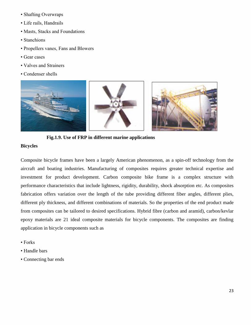
• Shafting Overwraps
• Life rails, Handrails
• Masts, Stacks and Foundations
• Stanchions
• Propellers vanes, Fans and Blowers
• Gear cases
• Valves and Strainers
• Condenser shells
Fig.1.9. Use of FRP in different marine applications
Bicycles
Composite bicycle frames have been a largely American phenomenon, as a spin-off technology from the
aircraft and boating industries. Manufacturing of composites requires greater technical expertise and
investment for product development. Carbon composite bike frame is a complex structure with
performance characteristics that include lightness, rigidity, durability, shock absorption etc. As composites
fabrication offers variation over the length of the tube providing different fiber angles, different plies,
different ply thickness, and different combinations of materials. So the properties of the end product made
from composites can be tailored to desired specifications. Hybrid fibre (carbon and aramid), carbon/kevlar
epoxy materials are 21 ideal composite materials for bicycle components. The composites are finding
application in bicycle components such as
• Forks
• Handle bars
• Connecting bar ends

24
Aircraft industry
The use of fibre reinforced composites has become increasingly attractive alternative to the conventional
metals for many aircraft components owing to its increased strength, durability, corrosion resistance,
resistance to fatigue and damage tolerance characteristics. Composites also provide greater flexibility as the
material can be tailored to meet the design requirements and they also offer significant weight advantages.
Carefully designed individual composite parts, at present, are about 20-30% lighter than their conventional
metal counterparts. This allows materials engineers to design structures with specific behaviour. They can
design a structure like the Grumman X-29 experimental plane that has forward-swept wings that do not
bend up at the tips like typical metal wings do during flight. The greatest value of composite materials is
that they can be both lightweight and strong. The heavier an aircraft weighs, the more fuel it burns. Modern
military aircraft, like the F-22, use composites for at least a 1/3 of their structures, and some experts have
predicted that future military aircraft will be more than 2/3 composite materials.
Fig 1.10. Use of FRP in aircraft applications

25
1.6.2. Electrical and Electronics
Composites equipped with good electric insulation, antimagnetic and spark-free, good adhesion to glue and
paint, self-extinguishing qualities are used for the construction of distribution pillars, link boxes, profiles
for the separation of current-carrying phases to disrupt short circuits etc. The other potential applications of
composites in this sector are:
• Third rail covers for underground railway
• Structures for overhead transmission lines for railway
• Power line insulators
• Lightning poles
• Power pole cross arms
• Fibre optic tensile members
• Switchgear frames
1.6.3. Construction
Construction holds priority for the adaptation of composites in place of conventional materials being used
like doors and windows, panelling, furniture, non-structural gratings, long span roof structures, tanks,
bridge components and complete bridge systems and other interiors. Components made of composite
materials find extensive applications in shuttering supports, special architectural structures imparting
aesthetic appearance, large signage etc. with the advantages like corrosion resistance, longer life, low
maintenance, ease in workability, fire retardancy etc.
Fig 1.11. Different construction by FRP composites

26
Usage of composites for damage repairing, seismic retrofitting and upgrading of concrete bridges finds
increased adoption as a way to extend the service life of existing structures, they are also being considered
as an economic solution for new bridge structures. Composite based 2D and 3D grid-type reinforcement for
concrete structures shows considerable potential for use as reinforcement of concrete in tunnels because of
its corrosion and chemical resistance, its lightweight and its ease of forming to fit curvatures. Grid-type
reinforcement for concrete structures consists of high-performance fibres such as glass, carbon, aramid and
hybrids impregnated with resin systems ranging from vinyl esters and other thermosetting resin systems to
thermoplastics. The significant systems-level savings were achieved due to the factors of weight. Other
critical applications of composites in the civil engineering area are:
• Tunnel supports
• Supports for storage containers
• Airport facilities such as runways and aprons
• Roads and bridge structures
• Marine and offshore structures
• Concrete slabs
• Power plant facilities
• Architectural features and structures such as exterior walls, handrails, etc.
1.6.4. Offshore Oil and Gas Industry
Steel and concrete are the materials of choice for offshore oil and gas production platforms, with steel
dominant in the topside applications. Composites have found their way into limited applications,
particularly where corrosion and the need to reduce high maintenance costs have been an issue. As the
industry moves to greater water depths, the significance of weight saving has become increasingly
important in conjunction with the application of buoyant tension for the leg structures. Composites may
find excellent usage in fabrication of the following:
• Profiles for oil pollution barriers
• Gratings, ladders and railings on oil-drilling platforms and ships
• Walkway systems
• Sucker rods

27
1.6.5. Consumer and Sports Goods
The optimum design of sports equipment requires the application of a number of disciplines, not only for
enhanced performance but also to make the equipment as user-friendly as possible from the standpoint of
injury avoidance. In designing sports equipment, the various characteristics of materials must be
considered. Among these characteristics are strength, ductility, density, fatigue resistance, toughness,
modulus (damping), and cost. To meet the requirements of sports equipment, the materials of choice often
consist of a mixture of material types - metals, ceramics, polymers and composite concepts. Following are
the general consumer and sports goods where there is lot of potential for composites in the near future:
• Canoes and Kayaks
• Vaulting Pole
• Golf and Polo rods
• Archery equipment
• Javelin
Fig1.12. Use of FRP in different applications

28
1.6.6. Chemical Industry
Chemical Industry Supplemented by the advantages of composites of lightweight, mouldability, fire
resistance properties, resistance to chemicals has made the material popular in the chemical industry.
Composites are extensively used in industrial gratings, structural supports, storage tanks, scrubbers,
ducting, piping, exhaust stacks, pumps and blowers, columns, reactors etc. for acidic and alkaline
environments. Some of the potential applications are:
• Composite vessels for liquid natural gas for alternative fuel vehicle
• Racked bottles for fire service, mountain climbing
• Double-wall FRP vessels with an early warning system for leakage detection
• Underground storage tanks
• Casings for electrostatic precipitator
• Drive shafts
• Fan blades (for both axial and centrifugal fans)
• Ducts and Stacks
• Aerial man-lift device

29
Chapter 2
LITERATURE SURVEY

30
2.1 Interfaces and Interphases in Composites:
The word “interphases” refers to a region where the fiber and matrix phases are chemically or mechanically
combined or otherwise indistinct [15]. An “interface” is a boundary demarcating distinct phases such as
fiber, matrix, coating layer, or interphase [10].
Usually, it is accepted that the interphase region has a thickness of 100nm to 500 nm. [15]
Fig.2.1 Fiber-matrix interface and interphase [10]
Advanced composites cannot be manufactured with good performance without optimum adhesion and
appropriate interphases [13]. Interfacial interactions and interphases play a key role in all multicomponent
materials irrespective of the number and type of their components or their actual structure. They are equally
important in particulate filled polymer, polymer blends, and fiber reinforced advanced composites,
nanocomposites or biomaterials. Although the role and importance of interfaces and interphases are same
for all multicomponent materials, surface modification must be always selected according to the objectives
targeted, as well as to the characteristics of the particular system [14].
Thus the integrity of the composite as a whole depends upon the ease and effectiveness with which a load
can be transferred within the composite. Thus the interface, i.e. the boundary across which load is
transferred serves as the heart of composite, which implies, the mechanical behavior of a composite
material is decisively controlled by the fiber-matrix interface
Fiber/matrix

31
2.2 The Failure Analysis
Fractography technique is used to study micro-mechanisms of fracture, investigate of failure in laboratory
structures, and post-mortem investigation of in-service components. The basic approach is to characterize
the fracture morphologies of specimens failing under known (pure) failure modes, and then comparing
these morphologies to 'unknown' failures. In composites the main causes of failure can be summed up as:
1. De-lamination.
2. Interfacial De-bonding (separation of fibers &matrix).
3. Microcracking of the matrix.
4. Fiber pull-out
5. Breaking of fibers
6. Stress redistribution
7. Longitudinal matrix splitting
Fracture modes in composites can be divided into three basic fracture types
a) Interlaminar
b) Intralaminar
c) Translaminar
When considered on microscale, interlaminar and intralaminar fracture types can be similarly described. In
both cases, fracture occurs on a plane parallel to that of the fiber reinforcement. In a similar manner to that
described for metals ,fracture of either type can occur under mode I tension, mode II in-plane shear,
mode III anti- plane shear, or any combination of these load conditions. Translaminar fractures are
those oriented transverse to the laminated plane in which conditions of fiber fractures are generated.
Turning to the fracture models, two major models are presented in the literature: the cumulative fracture
model and the fracture propagation model. In the first model, the matrix is assumed not to contribute
directly to the tensile strength of the composites, although it provides a means to transfer the load in shear
to the fibres. The specimen is divided into layers (bundles) of a length defined as an ineffective length.
When the specimen is loaded, the fibre are assumed to be stressed uniformly and as the load increases the
fibres in each bundle start to break randomly and stresses are redistributed uniformly among the unbroken
fibres in each bundle. When a sufficient number of fibres in a bundle fail, the specimen fails [9].

32
2.2.1 Delamination
Delamination is a mode of failure for composite materials [18]. Modes of failure are also known as 'failure
mechanisms'. In laminated materials, repeated cyclic stresses, impact, or 3-point loading can cause layers to
separate, with significant loss of mechanical toughness. Delamination also occurs in reinforced concrete
structures subject to reinforcement corrosion, in which case the oxidized metal of the reinforcement is
greater in volume than the original metal. The oxidized metal therefore requires greater space than the
original reinforcing bars, which causes a wedge-like stress on the concrete. This force eventually
overcomes the relatively weak tensile strength of concrete, resulting in a separation (or delamination) of the
matrix above and below the reinforcing fibers [12].
The cause of fiber pull-out (another form of failure mechanism) and delamination is weak bonding [19].
Thus, delamination is an insidious kind of failure which tends to develops inside of the material, without
being obvious on the surface, much like metal fatigue. Delamination is a critical failure mode in
composite structures as it can degrade the laminate to such a degree that it becomes useless in service.
The interfacial separation caused by the delamination may lead to premature buckling of the
laminate, excessive vibration, intrusion of moisture, stiffness degradation and loss of fatigue life . The
delamination though in some cases may provide stress relief and actually enhance the performance of the
component [10].
Fig 2.2 Crack Opening Modes

33
2.2.2 Fiber Pull Out and Debonding:
At some distance ahead of the crack the fibers are in intact state. In the higher stress region near the tip,
they are broken, not necessarily along the crack plane. Immediately behind the crack tip fibers pull
out of the matrix. In some composites the stress near the crack tip could be a cause the fibers to
debond from the matrix before they break. When brittle fibers are well bonded to a ductile matrix,
the fibers tend to snap ahead of the crack tip, leaving behind bridges of matrix material that neck down
and fracture in a completely ductile manner.
Fig 2.3 Fiber Pull Out [16]
In fiber reinforced materials with both brittle fibers and brittle matrices, toughness is derived from
two sources. Firstly, if the crack can be made to run up and down every fiber in its path the there
will be a large amount of new surface created for a very small increase in crack area perpendicular to
the maximum principal stress - Interfacial Energy - and in order to get the fibers to break they have to
be loaded to their fracture strength and this often requires additional local elastic work, and
secondly if the fibers do not break and therefore bridge the gap then work must be done to pull
the fibers out of the matrix-fiber Pullout. Using simple geometric models we can estimate the
contribution of each of these processes to the overall toughness of the composite [17].

34
2.2.3 Matrix Microcracking
The first form of damage in laminates is often matrix micro cracking. They are intralaminar or ply cracks
that traverse through the thickness of the ply and run parallel to the fibers of the ply [18]. The most
common observable micro cracking is cracking in the 900 plies during axial loading in the direction. These
micro cracks are transverse to the loading direction and are often termed as the transverse cracks. Tensile
loading, fatigue loading, environment, and thermal cycling can all lead to microcrack formation [19].
Microcracks can form in any ply that has a significant component of the applied load transverse to the
fibers in that ply. Microcracks lead to degradation in properties of the laminate including changes in
effective moduli, Poisson ratios, and thermal expansion coefficients [20]. Although these changes are
sometimes small, microcracks can nucleate other forms of damage.
Fig 2.4 Matrix Microcracking [21]

35
2.2.4. Fiber Fracture
If the amount of stress being applied is unable to be sustained by the fibers when distributed on them by the
matrix due to the inability of the formation of strong interfacial bonds, breaking of fibers may occur. This
can take place if the glass fiber is aptly held by the matrix and will be followed by the rupture of the fibers
which may be due to the localized stress and strain fields in the fibrous composite.
Fig 2.5 Breaking of Fibers [21]

36
2.3 Effect of Temperatures
Effects of temperature on fibrous polymeric composites are one of the most difficult challenges for
neophytes and composite structure designers because it can dramatically change the response of the
composite materials. A material that exhibits ductile behaviour at room temperature may become brittle at
low temperatures or may soften and creep at elevated temperatures [22]. With these temperature
fluctuations changes in strength and or stiffness are observed as well. The effect of the combination
of thermal and mechanical stresses may well cause a change in mode and location of failure as well as a
change in threshold load factor needed to cause failure. It is very difficult to generalize the effect of change
of temperature. The matrix dominated properties are such as compressive, flexural, shear and
transverse properties are most affected by the temperature dependence on the matrix. Thermal
conditioning imparts better adhesion and thus, an improved ILSS value especially at the less
conditioning time [23]. When considering the temperature dependence for the physical properties of
many polymeric materials, various relaxation effects are extremely important. In polymer molecules
a dynamic mechanical relaxation occurs due to heat transfer between the intermolecular mode (strain-
sensitive mode) and the intra-molecular mode ( strain- insensitive mode) [24] . Thermal degradation of
resin involves chemical reaction and physical changes. Chemical reaction is represented by oxidation,
further cross-linking and further reaction of un-reacted monomers, while physical change is the visco-
elastic behaviour [25]. The visco-elastic yield behaviour generally depends upon the temperature and
loading rate. At the macromolecular scale chain scission and cross-linking affect the polymer network
and thus, alter the mechanical properties of the oxidized layer. At the macroscopic level, the
hindered shrinkage of the oxidized layer induces a stress gradient susceptible to initiate and propagate
cracks [26]. Thermal conditioning behaviour of glass/epoxy and car bon/epoxy composites is of special
interest, because of their expanding use for structural applications, where increased temperatures are
common environmental conditions. Fracture processes of polymers are strongly influenced by
deformation or yielding processes which depend on temperature and time. At very low temperature no
yielding is possible and fracture is brittle. At high temperatures two characteristic phenomena occur
after the yield point: strain softening and strain hardening. The specimens tested at a lower temperature
are characterized by a greater level of micro-cracking and de-lamination. These effects are believed due to
higher thermal residual stresses [25].
37
2.3.1 Effects of temperature on glass transition temperature of polymer
Organic matrix resins such as epoxies soften as the temperature is increased, when it passes
through the glass transition (Tg). Above the Tg, the resin exhibit a significant decreasing strength
and stiffness due to increased polymer chain mobility [26]. There are several factors which influence
the magnitude of the temperature region where the Tg occurs.
1. Composition of the resin molecule
2. Cross link density
3. The polar nature of the resin molecules functional groups
4. Curing agent or the catalyst
Tg is used for evaluating the flexibility of a polymer molecule and the type of response the Tg
polymeric material would exhibit to mechanical stress. Polymers above their Tg will exhibit Tg delayed
elastic response (visco-elasticity), while those above Tg will exhibit dimensions stability. General common
sense prevails that higher the Tg better the mechanical properties.
2.3.2. Effect of High Temperature
Thermal conditioning at above ambient temperature might possibly improve adhesion level at the
interfaces. Adhesion chemistry at the interface may be influenced by post-curing phenomena and this effect
is supposed to increase with more conditioning time limited by some optimum value [21]. Thermal
conditioning caused matrix shrinkage due to volatile loss and additional cure of matrix [39]. Glass/epoxy
composite plate’s losses their rigidity and strength at room temperature and high temperatures (50° C) [30].
At high temperatures above the glass transition temperature (Tg), polymer composites are susceptible to
thermo-oxidative degradation. Although the fibres are stable below Tg but the matrix and especially the
fiber–matrix interface can undergo degradation that affects the physical and mechanical properties of the
composite structures over time [29]. The response of fiber/matrix interface within the composite plays an
important role in determining the gross mechanical performance, because it transmitting the load from the
matrix to the fibers, which contribute the greater portion of the composite strength. Better the interfacial
bond better will be the ILSS, de-lamination resistance, fatigue and corrosion resistance.

38
2.4. Effect of Volume Fraction:
Fibers have a very high modulus along their axis, but have a low modulus perpendicular to their axis. If the
fibers are all parallel, the modulus of a fiber reinforced composite depends upon which direction you're
measuring. The modulus of the entire composite, matrix plus reinforce, is governed by the rule of mixtures
when measuring along the length of the fiber:
Ec = EfVf + EmVm
Ec is the modulus of the entire composite along the length of the fiber.
Ef is the modulus of the fiber along the length of the fiber.
Vf is the volume percent occupied by the fibers.
Em is the modulus of the matrix (usually not dependent upon direction)
Vm is the volume percent occupied by the matrix (equal to (1-Vf).
Fig 2.6. Comparison of Loading type on Strength and Modulus of Elasticity

39
2.5. Effect of Loading Rate
Composite structures undergo different loading conditions during their service life, e.g. sports equipment at
high loading rate to pressure vessels at low loading rates [31]. Composites are extensively being used in
applications where they are deformed rapidly. One of these applications is when composite jet engine
compressor blades are exposed to hazards of foreign object damage, such as bird impact on rotating blades,
this impact occurring at velocities of up to 300 m s−1
and being able to cause extensive damage to the
composite blade [32]. The effects of varying loading rates on mechanical properties of FRP composites are
investigated and observed thus leading to a variety of contradictory observations and conclusions [33]. E-
Glass fibers have been found to be rate sensitive, information available in literature was not extensive to
draw any substantial conclusion. Woven and unidirectional GFRP are rate dependent, both the modulus and
strength increase as the test rate are increased, strain to failure decrease with increasing strain rate [34, 35,
36].
Fig.2.7. Fiber alignments due to applied stress (a) before loading (b) after loading [6]

40
2.6 Temperature Modulated Differential Scanning Calorimetry:
Differential scanning calorimetry (DSC) is a technique for measuring energy necessary to establish a nearly
zero temperature difference between a substance and an inert reference material, as the given two
specimens are subjected to identical temperature regimes in an environment heated or cooled at a controlled
rate [39]. A new advanced technique of temperature-modulated DSC (TMDSC) combines the separation of
both sensible and latent heat flow and the measurement of the frequency-dependent heat capacity over a
wide frequency range. This technique is based on stochastic temperature modulation and yields the quasi-
static heat capacity and the frequency-dependent complex heat capacity without the need for additional
calibration procedure. Thus, it can be determined over a wide frequency range. A second result of the
analysis is the non-reversing heat flow. This is the non-correlated heat flow component. The reversing heat
flow is calculated from the quasi-static heat capacity. All these quantities and their frequency dependency
can be determined in one single measurement [38].
Fig. 2.8. Mettler -Toledo 821 with intra cooler for DSC measurements and reference sample
chamber

41
2.7 FTIR Imaging
Fourier transform infrared spectroscopy (FTIR) is a technique which is used to obtain an infrared spectrum
of absorption, emission, photoconductivity or Raman scattering of a solid, liquid or gas. An FTIR
spectrometer simultaneously collects spectral data in a wide spectral range. This confers a significant
advantage over a dispersive spectrometer which measures intensity over a narrow range of wavelengths at a
time. FTIR technique has made dispersive infrared spectrometers all but obsolete (except sometimes in the
near infrared) and opened up new application of infrared spectroscopy.
Fig.2.9. (a) FTIR spectrophotometer, (b) AIM-800 Automatic Infrared Microscope
The term Fourier transform infrared spectroscopy originates from the fact that a Fourier transform (a
mathematical algorithm) is required to convert the given raw data into the actual spectrum [38].
FTIR is most useful for identifying chemicals that are either organic or inorganic. It can be utilized to
quantitate some components of an unknown mixture. It can be applied to the analysis of solids, liquids, and
gasses. The term Fourier Transform Infrared Spectroscopy (FTIR) refers to a fairly recent development in
the manner in which the data is collected and converted from an interference pattern to a spectrum. Today's
FTIR instruments are computerized which makes them faster and more sensitive than the older dispersive
instruments [12].
Fourier transform spectroscopy is a less intuitive way to obtain same information. Rather than shining a
monochromatic beam of light at the sample, this technique shines a beam containing many different
frequencies of light at once, and measures how much of that beam is absorbed by the sample. Next, the
beam is modified to contain a different combination of frequencies, giving a second data point. This
process is repeated many times. Afterwards, a computer takes all these data and works backwards to infer
what the absorption is at each wavelength [39].

42
Chapter 3
Experimental

43
3.1 Experimental work:.
Fig.3.1. Brief explanation of experimental procedure
Glass Fibers and Carbon fibres are cut in size 20cm x 20cm to form 12 sheets (laminates) and weighed.
LY-556 Epoxy Resin based on Bisphenol A is weighed to be 40% & 50% of the total weight of the fiber and
resin.
Hardener HY 951(aliphatic primary amine) at the ratio 10% by wt. of Resin is used.
The Fiber Reinforced Polymer (FRP) Composite is prepared by Hand Lay-up
method, and is left for curing for 24 hours at room temperature.
Ambient Temperature
without any treatment.
Thermal conditioning
is done at 50°C
Short Beam Shear Test (Flexural Test) is carried out room temperature to evaluate the
value of inter-laminar shear strength (ILSS)at the crosshead speeds of 1,10,100,300,600
mm/min.
Fractrographic analysis is done using Scanning Electron Microscope.
Results and Discussion
Conclusion
1 hour 3 hour 5 hour 7 hour Ambient
FTIR graphs are plotted
Glass Transition Temperature is measured by using TMDSC

44
Chapter 4
Result and Discussions
45
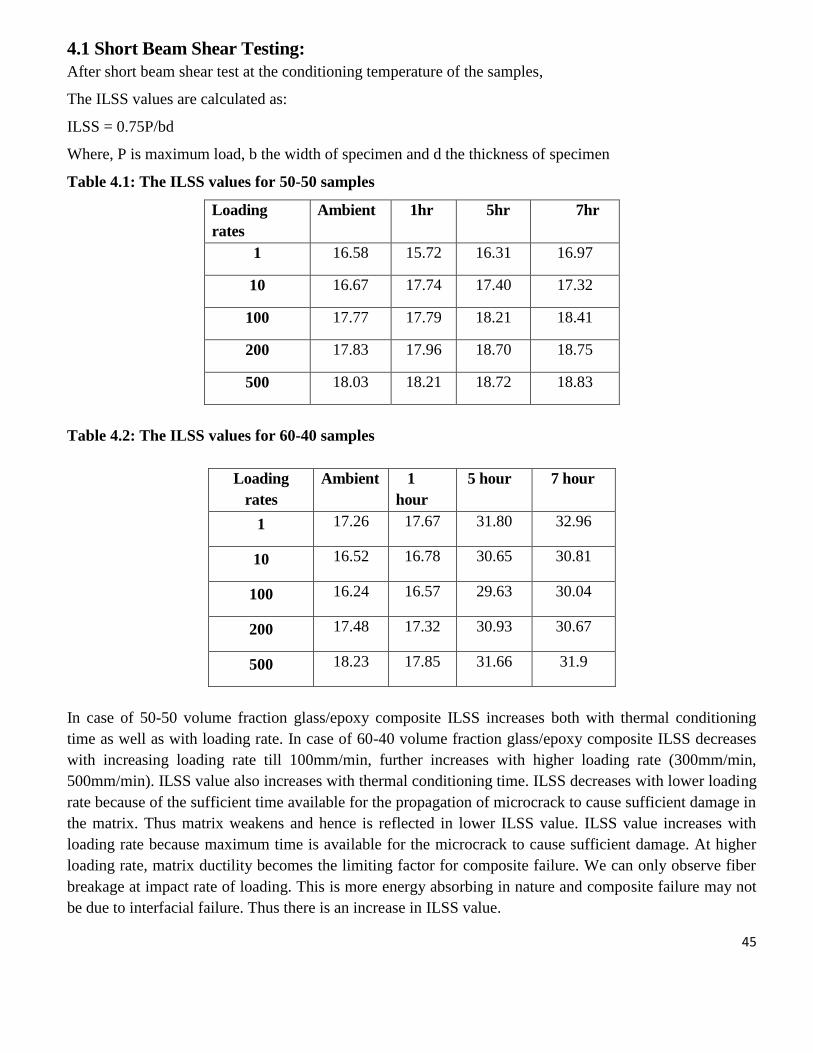
4.1 Short Beam Shear Testing:
After short beam shear test at the conditioning temperature of the samples,
The ILSS values are calculated as:
ILSS = 0.75P/bd
Where, P is maximum load, b the width of specimen and d the thickness of specimen
Table 4.1: The ILSS values for 50-50 samples
Loading
rates
Ambient 1hr 5hr 7hr
1 16.58 15.72 16.31 16.97
10 16.67 17.74 17.40 17.32
100 17.77 17.79 18.21 18.41
200 17.83 17.96 18.70 18.75
500 18.03 18.21 18.72 18.83
Table 4.2: The ILSS values for 60-40 samples
Loading
rates
Ambient 1
hour
5 hour 7 hour
1 17.26 17.67 31.80 32.96
10 16.52 16.78 30.65 30.81
100 16.24 16.57 29.63 30.04
200 17.48 17.32 30.93 30.67
500 18.23 17.85 31.66 31.9
In case of 50-50 volume fraction glass/epoxy composite ILSS increases both with thermal conditioning
time as well as with loading rate. In case of 60-40 volume fraction glass/epoxy composite ILSS decreases
with increasing loading rate till 100mm/min, further increases with higher loading rate (300mm/min,
500mm/min). ILSS value also increases with thermal conditioning time. ILSS decreases with lower loading
rate because of the sufficient time available for the propagation of microcrack to cause sufficient damage in
the matrix. Thus matrix weakens and hence is reflected in lower ILSS value. ILSS value increases with
loading rate because maximum time is available for the microcrack to cause sufficient damage. At higher
loading rate, matrix ductility becomes the limiting factor for composite failure. We can only observe fiber
breakage at impact rate of loading. This is more energy absorbing in nature and composite failure may not
be due to interfacial failure. Thus there is an increase in ILSS value.

46
0 100 200 300 400 500 600
15.5
16.0
16.5
17.0
17.5
18.0
18.5
19.0
ILS
S(M
Pa
)
Loading Rate(mm/min)
amb
1hr
3hr
5hr
7hr
Fig.4.1. ILSS vs. Crosshead speed for 50-50 Glass/epoxy composites
0 100 200 300 400 500 60016.0
16.5
17.0
17.5
18.0
18.5
ILS
S(M
Pa)
Loading Rate(mm/min)
amb
0 100 200 300 400 500 600
15.5
16.0
16.5
17.0
17.5
18.0
18.5
ILS
S(M
Pa)
Loading Rate (mm/min)
1hr
Fig.4.2. ILSS vs. Crosshead speed for Glass/epoxy composites at ambient and 500c for 1hr
0 100 200 300 400 500 600
16.0
16.5
17.0
17.5
18.0
18.5
19.0
ILS
S(M
Pa)
Loading Rate(mm/min)
5hr
0 100 200 300 400 500
16.5
17.0
17.5
18.0
18.5
19.0
ILS
S(M
Pa
)
Loading Rate(mm/min)
7hr
Fig4.3. ILSS vs. Crosshead speed for Glass/epoxy composites at 500c for 5hr and 7hr

47
0 100 200 300 400 500 600
16
18
20
22
24
26
28
30
32
34
ILS
S(M
Pa)
Loading Rate(mm/min)
amb
1hr
5hr
7hr
Fig.4.4. ILSS vs. Crosshead speed for 50-50 Glass/epoxy composites
0 100 200 300 400 500 600
12
13
14
15
16
17
18
19
20
ILS
S(M
Pa
)
Loading Rate(mm/min)
amb
0 100 200 300 400 500 600
14.0
14.5
15.0
15.5
16.0
16.5
17.0
17.5
18.0
18.5
19.0
ILS
S(M
Pa)
Loading Rate(mm/min)
1hr
Fig.4.5. ILSS vs. Crosshead speed for Glass/epoxy composites at ambient and 500c for 1hr
0 100 200 300 400 500 600
25
26
27
28
29
30
31
32
33
34
35
ILS
S(M
Pa)
Loading Rate(MPa)
5hr
0 100 200 300 400 500 600
25
26
27
28
29
30
31
32
33
34
35
ILS
S(M
Pa
)
Loading Rate(mm/min)
7hr
Fig.4.6. ILSS vs. Crosshead speed for Glass/epoxy composites at 500c for 5hr and 7hr

48
4.2 DSC Analysis
40 60 80 100 120
-1.0
-0.5
0.0
amb,Tg =73.300c
1 hr, Tg =74.550c
3 hr, Tg =75.620c
5 hr, Tg =76.070c
7 hr, Tg =76.370c
Am
ou
nt o
f h
eat(M
w)
Tempearture(oc)
-1 0 1 2 3 4 5 6 7 8
60
65
70
75
80
Tg
(0c
)
Time(in Hour)
73.300c
74.550c
75.620c
76.070c 76.37
0c
Fig.4.7. DSC graphs and plot of Tg of 50-50 glass/epoxy composite
40 60 80 100 120
-1.0
-0.5
0.0
Am
ou
nt o
f H
eat(M
W)
Temperature(0c)
amb ,Tg =73.070c
1 hr,Tg =76.150c
3 hr,Tg =76.610c
5 hr,Tg =76.960c
7 hr,Tg =76.990c
-1 0 1 2 3 4 5 6 7 8
60
65
70
75
80
Tg
(0c
)
Time(in Hour)
73.070c
76.150c 76.61
0c 76.96
0c 76.99
0c
Fig.4.8. DSC graphs and plot of Tg of 60-40 glass/epoxy composite

49
It is very important to measure glass transition temperature (Tg) because it provides the critical service
temperature of the polymer composites. Polymer composites are useful at a temperature below their Tg
value. But when they are exposed to thermal conditioning, the Tg value usually increases. Here, DSC
analysis shows Tg value increases with increase in thermal conditioning time w.r.t ambient Tg value for
glass/epoxy composites. The increase in value may be due to interpenetrating network (IPN). Two
independent networks are created during curing of epoxy, they penetrate each other but are not being
covalently bonded. The mixture of this two independent network is called interpenetrating network (IPN).
This delays the transition from glassy to rubbery state as a result Tg value increases. With increasing Tg the
ILSS may increases initially. Hence we are tempted to assume that there is enhancement of mechanical
properties.
4.3. FTIR Analysis
From the FTIR analysis the band at 550-650 cm-1 is the spectra range of 50/50 volume fraction of the
glass/epoxy system. We can also observe that there is a shifting of bandwidth with decrease in thermal
conditioning time. Two new transmitting peaks at 450-500cm-1
spectrum range at higher thermal
conditioning time and another peak at 600-650cm-1 is observed in the spectrum range at lower thermal
conditioning time of 60/40 volume fraction of the glass/epoxy system. The glass/epoxy composite shows a
bond formation between glass fiber and epoxy resin.
500750100012501500175020002500300035004000
1/cm
0
50
100
150
200
250
300
350
%T
60 40 AMB 500750100012501500175020002500300035004000
1/cm
0
75
150
225
300
375
450
%T
50 50 AMB (a) (b)
500750100012501500175020002500300035004000
1/cm
0
50
100
150
200
250
300
350
400
450
%T
60 40 1 HR 500750100012501500175020002500300035004000
1/cm
50
75
100
125
150
175
200
225
250
275
%T
50 50 1 HR (c) (d)

50
500750100012501500175020002500300035004000
1/cm
50
100
150
200
250
300
350
%T
60 40 3HR 500750100012501500175020002500300035004000
1/cm
0
50
100
150
200
250
300
350
400
%T
50 50 3 HR (e) (f)
500750100012501500175020002500300035004000
1/cm
0
50
100
150
200
250
300
350
400
%T
60 40 5HR 500750100012501500175020002500300035004000
1/cm
0
75
150
225
300
375
450
%T
50 50 5 HR (g) (h)
500750100012501500175020002500300035004000
1/cm
50
100
150
200
250
300
350
400
%T
60 40 7HR 500750100012501500175020002500300035004000
1/cm
0
50
100
150
200
250
300
350
400
450
%T
50 50 7 HR (i) (j)
Fig.4.9. 2D micrographs taken by FTIR spectrophotometer of glass/epoxy composites of 60-40 at
500c for different duration period (a) & (b) untreated, (c) & (d) for 1 hour, (e) & (f) for 3 hour, (g)
& (h) for 5hour, (i) & (h) for 7 hour respectively.

51
4.4. Failure Analysis by SEM:
The Scanning Electron Micrographs revealed different modes of failure at high temperature in different
conditions and at varying crosshead speed. The majority of them being as follows:
Fig 4.10 SEM showing matrix crazing with riverline images
Fig.4.11. SEM representing matrix shearing
This matrix shearing is found in 60-40 untreated glass/epoxy composite which may lead to degradation in
properties of the laminate including changes in effective moduli, Poisson ratios, and thermal expansion
coefficients.
Matrix Crazing
Matrix Shearing
SSSShearing

52
Fig. 4.12 SEM representing debonding
This type of failure modes happen at higher temperature by treatment of 1hours. This mode of fracture
may happen because snapping of brittle fiber ahead of the crack tip, leaving bridges of ductile matrix
material that neck down and fracture in a completely ductile manner.
Fig. 4.13 SEM showing Fiber Fracture
Fiber Fracture can take place if the glass fiber is aptly held by the matrix and will be followed by the
rupture of the fibers which may be due to the localized stress and strain fields in the fibrous composite.
This failure mode is done at higher thermal conditioning at500c at 1 hour.
Debonding
Fiber Fracture

53
Chapter 5
Conclusion

54
FRP composites come under attack in harsh and hostile conditions which leads to a major area of concern.
The heterogeneous nature of glass Fiber Reinforced Composite makes the process of its failure quite
cumbersome and complex. In the present research work, it has been tried to explain the failure mechanism
possibly occurring in the tested samples on the basis of established theories through ILSS values, SEM
fractography, and FTIR and TMDSC graphs. A rigorous endeavor has been made to estimate macro-
mechanics of the possible modes of failures. The ILSS curves reveal the possible effect of different kinds
of treatment by observing carefully the fracture surface of the composite as shown by the SEM
micrographs, the factors affecting their respective failure could be determined.
The degree of polymerization under different working temperatures is critically compared by FTIR images.
The results of TMDSC suggest that there is an increase in the glass transition temperature and thus it
enhance the mechanical properties of samples. From the results, it is also acknowledged that, GFRP gives
enhanced service life at high temperature conditioning. Summarizing all the above results, we may
conclude that, high thermal conditioning leads to enhanced polymerization and thus the matrix gets harder
and also, there is enhanced interfacial property.

55
Chapter 6
Scope of the Future

56
In summary the present piece of work leaves a wide scope for future investigators to explore many other
aspects of thermal conditioned FRP composites at different temperatures and different duration time period.
The complex failure mechanisms of glass/epoxy require more experimentation for a better characterization
of these materials. Implications of thermal conditioning most often lead an improved adhesion of the
interface at above ambient temperatures.

57
References:
1. What Is a Composite? By Todd Johnson, About.com Guide.
2. Hull D. and Clyne T.W. “An Introduction to Composite Materials”, Second Edition, Cambridge Solid
State Science Series, 1995.
3. Miracle D.B. and Donaldson S.L., “Introduction to Composites”, ASM Hand Book of Composite
Materials, 21, 2001.
4. Callister W D., “Materials Science and Engineering-An Introduction”, John Wiley and Sons, 2001.
5. Meurs P.F.M., Schreurs P.J.G., Peijs T., Meijer E.H., “Interphase Conditions In Composite Materials”
Composites, Part A 27A, 781, 1996.
6. O'Brien, TK, "Delamination Durability of Composite Materials for Rotorcraft," NASA/ Army
Rotorcraft Technology, NASA CP, 2495, 573, 1988.
7. Ray P.K. , Bhushan A., Bera T., Ranjan R., Mohanty U.K., Vadhera S., Ray B.C. “Mechanical
Behavior of hygrothermally conditioned FRP composites after thermal spikes.”, Proceedings of the
Emerging Trends in Structural Mechanics and Composites,322, 2003.
8. Bao, Li.R. and Yee O.F.,“Woven Glass fabric/polyester composites:effect on interface” Polymer, 43,
3987, 2002.
9. H.H. Abdelmohsen “Simulation of tensile strength of anisotropic fibre-reinforced composites at low
temperature” Cryogenics , 31, 1991.
10. Jang B Z., “Advanced Polymer Composites: Principle and Applications” ASM International, Materials
Park, OH, 1994.
11. Aggarwal B D, Broutman L J., “Analysis and performance of Fiber Composites” Canada, Wiley Inter
science, 1990.
12. http://en.wikipedia.org as retrieved on 5th May 2011.
13. http://www.netcomposites.com/calendar_details.asp?976, Proceedings at Interfaces and Interphases in
Multicomponent Materials (IIMM 2010), University of Sheffield, UK , 1 - 3 September 2010.
14. Pukánszky B, “Interfaces and interphases in multicomponent materials: past, present, future”,
European Polymer Journal, 41, 4, 645, 2005.
15. Dalai R.P, Ray B.C,“ An Assessment of Mechanical Behaviours of Fibrous Polymeric Composites
Under Different Loading Speeds at Above- and Sub – Ambient Temperatures ”, Master in Technology
Thesis, NIT Rourkela, 2010.
16. www.ultramet.com
17. Knops M., Bogle C., “Gradual failure in fiber/polymer laminates.” Composites Science And
Technology, 66, 5,2006.
18. Nairn J.A, Hu S, Talreja R, “Damage Mechanics of Composite Materials”, Elsevier Science, The
Netherlands, 187, 1994.
19. Nairn J.A, Talreja R, Manson J.-Å. E. “Polymer Matrix Composites”, Elsevier Science, The
Netherlands, 403, 2000.
20. McCartney L. N. , “Composite Science & Technology”, 60, 2255, 2000.
21. Deb S.K, Chiranjeevee “Revealing of failure modes of FRP composites by microscopic techniques”,
Bachelor in Technology Thesis, NIT Rourkela, 2010
22. Kellogg K G, Patil R, Kallmeyer A R, Dutta P K. Effect of Load Rate on Notch Toughness of Glass
FRP Subjected to Moisture and Low Temperature , International Journal of Offshore and Polar
Engineering, 15(1), (2005):pp. 54–61
23. Ray B C. Adhesion of glass/epoxy composites influenced by thermal and cryogenic environments,
Journal of Applied Polymer Science, 102(2) (2006): pp.1943-1949.

58
24. Yano O and Yamaoka H. Cryogenic Properties of Polymers, Progress in Polymer Science,
20(1995):pp.585-613
25. Naruse T, Hattori T, Miura H, Takahashi K. Evaluation of thermal degradation of unidirectional
CFRP rings, Composite Structures, 52 (2001):pp. 533-538.
26. Seyler R J. Assignment of the Glass Transition, Philadelphia, ASTM STP 1249, 1994
27. Wang.Y, Thomas H. Hahn. AFM characterization of the interfacial properties of carbon fiber
reinforced polymer composites subjected to hygrothermal treatments ,Composites Science and
Technology, 67 (2007):pp. 92-10
28. Aktas M, Karakuzu R. Determination of mechanical properties of glass-epoxy composites in high
temperatures, Polymer Composites, 30 (2009) :pp.1437-1441
29. Barjasteh E, Bosze E J, Tsai YI, Nutt S R. Thermal aging of fiberglass/carbon-fiber hybrid
composites, Composites Part A, 40 (2009):pp. 2038-2045
30. Callister W D., “Materials Science and Engineering-An Introduction”, John Wiley and Sons, 2001.
31. Kanchanomai C, Rattananon S, Soni M. , “Effects of loading rate on fracture behavior and mechanism
of thermoset epoxy resin”, Polymer Testing, 24,886,2005
32. Hamouda A. M. S., Hashmi M. S. J. ,“Testing of composite materials at high rates of strain: advances
and challenges”,Journal of Materials Processing Technology, 77,1,327,1998.
33. Jacob G C, Starbuck J M, Fellers J F, Simunovic S, Boeman R G. , “Strain Rate Effects on the
Mechanical Properties of Polymer Composite Materials”, Journal of Applied Polymer Science, 94,
296,2004
34. Saniee F F, Majzoobi G H, Bahrami M. ,“An experimental study on the behavior of glass–epoxy
composite at low strain rates”, Journal of Materials Processing Technology, 162,39,2005
35. Harding, J. & Welsh, L. M., “A tensile testing technique for fibre-reinforced composite at impact rates
of strain” , Journal of material Science, 18,1810,1983
36. Ochola R.O, Marcus K, Nurick G N and Franz T. , “Mechanical behaviour of glass and carbon fibre
reinforced composites at varying strain rates” , Composite Structures, 63,455, 2004
37. http://www.eurostar-science.org/MAP1/Schawe.pdf
38. http://www.wcaslab.com/tech/tbftir.htm
39. Griffiths P., de Hasseth J.A., “Fourier Transform Infrared Spectrometry” (2nd ed.). Wiley-Blackwell,
2007