An Arduino-based MIDI Controller for Detecting Minimal ...1058266/FULLTEXT01.pdf · for Detecting...
31
IT 16054 Examensarbete 15 hp Juni 2016 An Arduino-based MIDI Controller for Detecting Minimal Movements in Severely Disabled Children Mattias Linder Institutionen för informationsteknologi Department of Information Technology
Transcript of An Arduino-based MIDI Controller for Detecting Minimal ...1058266/FULLTEXT01.pdf · for Detecting...

IT 16054
Examensarbete 15 hpJuni 2016
An Arduino-based MIDI Controller for Detecting Minimal Movements in Severely Disabled Children
Mattias Linder
Institutionen för informationsteknologiDepartment of Information Technology
Teknisk- naturvetenskaplig fakultet UTH-enheten Besöksadress: Ångströmlaboratoriet Lägerhyddsvägen 1 Hus 4, Plan 0 Postadress: Box 536 751 21 Uppsala Telefon: 018 – 471 30 03 Telefax: 018 – 471 30 00 Hemsida: http://www.teknat.uu.se/student
Abstract
An Arduino-based MIDI Controller for DetectingMinimal Movements in Severely Disabled Children
Mattias Linder
In therapy, music has played an important role for children with physical and cognitive impairments. Due to the nature of different impairments, many traditional instruments can be very hard to play. This thesis describes the development of a product in which electrical sensors can be used as a way of creating sound. These sensors can be used to create specially crafted controllers and thus making it possible for children with different impairments to create music or sound. This thesis examines if it is possible to create such a device with the help of an Arduino micro controller, a smart phone and a computer. The end result is a product that can use several sensors simultaneously to either generate notes, change the volume of a note or controlling the pitch of a note. There are three inputs for specially crafted sensors and three static potentiometers which can also be used as specially crafted sensors. The sensor inputs for the device are mini tele (2.5mm) and any sensor can be used as long as it can be equipped with this connector. The product is used together with a smartphone application to upload different settings and a computer with a music work station which interprets the device as a MIDI synthesizer.
Tryckt av: Reprocentralen ITCIT 16054Examinator: Olle GällmoÄmnesgranskare: Mikael LaaksoharjuHandledare: Lars Oestreicher

Contents
1 Introduction 31.1 Background . . . . . . . . . . . . . . . . . . . . . . . . . . . . . . . . . . . . . . . 31.2 Research question . . . . . . . . . . . . . . . . . . . . . . . . . . . . . . . . . . . . 41.3 Delimitation . . . . . . . . . . . . . . . . . . . . . . . . . . . . . . . . . . . . . . . 4
2 Similar and related products 52.1 Related work . . . . . . . . . . . . . . . . . . . . . . . . . . . . . . . . . . . . . . 52.2 Similar hardware . . . . . . . . . . . . . . . . . . . . . . . . . . . . . . . . . . . . 52.3 MIDI . . . . . . . . . . . . . . . . . . . . . . . . . . . . . . . . . . . . . . . . . . . 6
3 Digital music instruments 7
4 Overview of product 94.1 Music workstation . . . . . . . . . . . . . . . . . . . . . . . . . . . . . . . . . . . 9
5 Software 105.1 Routing MIDI messages . . . . . . . . . . . . . . . . . . . . . . . . . . . . . . . . 10
5.1.1 Hairless-midiserial . . . . . . . . . . . . . . . . . . . . . . . . . . . . . . . 105.2 iPhone Design . . . . . . . . . . . . . . . . . . . . . . . . . . . . . . . . . . . . . . 11
6 Final prototype 16
7 System 177.1 Setup . . . . . . . . . . . . . . . . . . . . . . . . . . . . . . . . . . . . . . . . . . 177.2 Calibration . . . . . . . . . . . . . . . . . . . . . . . . . . . . . . . . . . . . . . . 177.3 Running . . . . . . . . . . . . . . . . . . . . . . . . . . . . . . . . . . . . . . . . . 18
8 Hardware 198.1 Arduino . . . . . . . . . . . . . . . . . . . . . . . . . . . . . . . . . . . . . . . . . 198.2 Bluetooth low energy . . . . . . . . . . . . . . . . . . . . . . . . . . . . . . . . . . 198.3 Sensors and similar components . . . . . . . . . . . . . . . . . . . . . . . . . . . . 208.4 Development . . . . . . . . . . . . . . . . . . . . . . . . . . . . . . . . . . . . . . 21
9 Summary 259.1 Performance . . . . . . . . . . . . . . . . . . . . . . . . . . . . . . . . . . . . . . . 259.2 Conclusion . . . . . . . . . . . . . . . . . . . . . . . . . . . . . . . . . . . . . . . 259.3 Future work and improvements . . . . . . . . . . . . . . . . . . . . . . . . . . . . 26
1

1 Introduction
Programming with different micro controllers has recently become more and more common forvarious types of tasks. Micro controllers and different modules for these chips become cheaperand more accessible [28]. With a cheap micro controller and some sensors there is much that canbe done. This thesis project aims to use a collection of three components, namely a microchip,arbitrary analogue sensors and a smart phone [11], to allow severely disabled children to createsound and even music. The idea of this part of the project is that one should be able toconnect a sensor to an input on a microchip, tell that microchip what that input regulates,via an application on a phone, and then start generating sound on software synthesizers withthe input from the different sensors. This thesis project is made as a part of a larger project,MuMin (Maximum Output and Minimal Interaction) [35], for the VI2 unit at the departmentof Information Technology at Uppsala University. The main focus for the whole project is toenable children with very severe cognitive and/or physical disabilities to be able to create musicon their own accord, with an electronic instrument. The project runs in close connection withthe Arsta special school in Uppsala. The outcome of the project is intended to be used by themusic teachers and special pedagogues at Arsta special needs school, and possibly also later inother schools around Sweden.
1.1 Background
Music has been a very important part of the therapy for children with severe cognitive andphysical impairments. Learning to play an instrument can have many positive effects, includingimproved attention, improved social skills, better memory and more [33] [31].
However, due to the nature of the impairments music therapy becomes mainly a semi-passiveactivity for the children, that is, where the child either is listening to the music or follows theteachers piano playing by hitting a drum, or special single string guitars. Traditional musicinstruments, however, often require a relatively large physical effort and coordination, somethingthat many of these children lack. The children of the target group are severely impaired, mostof them with multiple impairments. The communication means are very limited, and few ofthem have a spoken language. The teachers use a simple sign language to communicate withthe children, and they often have to rely on their personal experience of each individual child.
The overall intention with this project, for which this thesis is written, is to enable thechildren in this specific target group to take a more active part in generating music. The basicidea is that through the use of synthesizers and specially designed controllers, the children canuse their individual abilities to produce music, instead of taking a passive role. Each child hascertain physical and cognitive skills, which will be the focus of the design for the controller thatis adapted to him or her.
Since the controllers are individually designed, there is also a need to be able to connect themto the synthesizer, and this is where the current thesis comes in. Using an Arduino [4] board,the aim is to create a micro controller that converts the controller signals to MIDI (MusicalInstrument Digital Interface) [20]. Ideally a new controller should be more or less plug-and-play, albeit with a possibility to make some smaller adjustments if needed. The applicationshould be using an iPhone or iPad [14] for the interface, since this is a tool that is used at theschool in question.
Initially the project used ”traditional” hardware controls, e.g., drum pads, ribbon controllers,and very sensitive keyboards. One special instrument used is the Theremin by Moog [12], whichcan be controlled with small movements of a single finger.
3

1.2 Research question
The challenges in this thesis project have been to make a MIDI controller, that is, a devicethat can generate MIDI messages, using a simple interface, that still can use any kind of controlsensor without the user needing to know anything about the technical issues around the devices.This thesis aims to answer the following questions:
• Is it possible to create a small MIDI controller that receives signals from analogue sensorsand then generates appropriate MIDI signals?
• What are the limitations of the Arduino for this kind of application?
Apart from the research questions, the project aims at producing a working prototype as anend result.
1.3 Delimitation
The focus of this project is to make a phone application only for iOS [14]. Further, the controlunit (the iPhone application) and the micro-controller will only communicate through bluetoothBLE [29] (also referred to as BLE, bluetooth low energy, bluetooth LE or bluetooth smart).There will also be a limitation of how many different MIDI messages that can be generated bya normal user. If the user have more knowledge about MIDI messages, then there will be anoption in the application where the user can input exactly what the microchip should send.
4
2 Similar and related products
2.1 Related work
There are many actors on the market who are creating technology in which computers controldevices though different sensors. Below is a list of some of the bigger actors and their products.
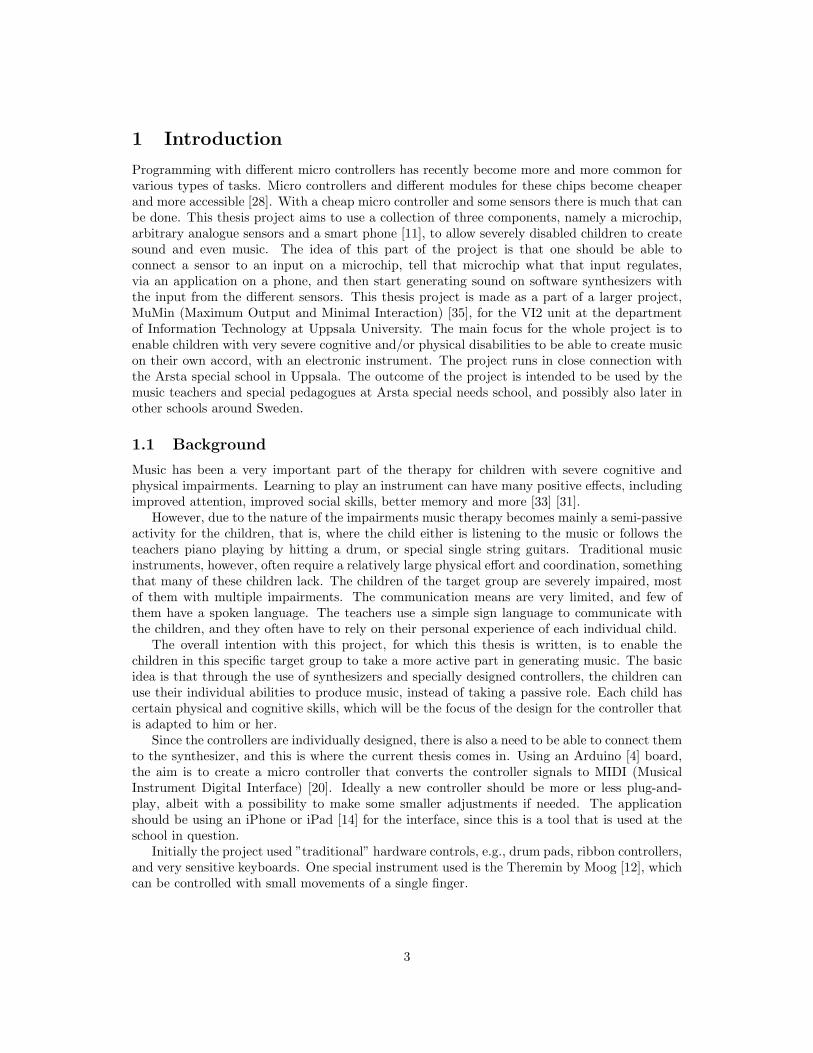
TouchTone [6] is an electrical music instrument designed for children with Cerebral palsy [8].It uses pressure sensitive pads to generate tones and a shift that is used to change the octaveof the tones (see Figure 1). This makes it easier for the children to be creative when creatingsound and music. Every pad has a led light which is used when a user wants learn a song or afollow an exercise.
Soundscraper (or Ljudskrapan) [23] is a system designed to help children with special needsto create and explore music. It does that by having a similar design as this project. It usesdifferent controllers or cameras to catch the users movement and then produce different sounds.
Figure 1: TouchTone instrument.
2.2 Similar hardware
littleBits Electronics [19] is a company based in New York. Their product offers an easy way tobuild your own electrical solutions and inventions using prebuilt electrical modules. littleBits hasseveral modules that can be used to create a synthesizer. They offer several different modules,for example an oscillator and a pulse regulator. These modules are easy to connect, you just haveto put them next to each other and a magnet will pull them together and create a connectionbetween them.
Makey Makey [16] is a product invented by MIT Media Lab, Cambridge, U.S. Makey Makeyis a micro controller that can read analogue input from almost any material, the material justneeds to be able to conduct a tiny bit of electricity.
A material (e.g. a fruit or a potato) is connected to the Makey Makey by an alligator clipper.Another material (e.g. the users body) is connected to ground. When the two materials touch,a connection is made and is read by the Makey Makey board. When the materials touch, theinput is translated into a digital signal, either 0 or 1. The signal is then mapped onto a key onthe keyboard of a computer, making that signal controlling that key on the computer.
Microsoft kinect [3] is a motion sensor device created by Microsoft, U.S. It has the appearanceof a web-camera with the difference that it can read its surrounding, making it possible to controla computer by using different gestures. The camera of the kinect should be faced against theobject that is going to act as a controller. The kinect can then sense when gestures from thatobjects are made.
5

Leapmotion [32] is a company based in the U.S. Their product is similar to Microsoft kinect,the difference being that Leapmotion is placed on a desktop, with a sensor facing upwards, andthen reads movement and gestures that are made above the device.
Myo [34] is a gesture control device made by Thalmic Labs located in Canada. It is anarmband that lets the user wirelessly control technology with gestures and motion. It supportsboth motion and hand gesture detection through EMG (Electromyography) muscle detection.
2.3 MIDI
MIDI is a protocol used for different electronic instruments and computers to communicate witheach other. The protocols describes what a MIDI message should contain and what differentmessages do. Every MIDI message is divided into two categories: the status and the data. Thestatus byte indicates what type of information is being sent. For example the status byte cantell that there should be a note plying or there should be a pitch bending. The data portion ofthe message tells what values are associated with the status part [20].
An example of how a MIDI message could look like: the status part is the binary number144, and the following data bytes could then be 61 followed by 100. The status byte 144 meansthat a note should be played. The first data byte 61 tells that the note C in octave 4 should beplayed and the following byte 100 tells at which volume the note should be played.
6

3 Digital music instruments
There are several theories about what makes a good instrument. Sergi Jorda suggests in hispaper [25] that there are chances that absolute beginners will prefer an instrument that seems tooffer more varied possibilities, meaning the instrument is very adaptable. However, professionalswill be more satisfied with an instrument with a stronger personality, meaning a less adaptableinstrument. He also notes that using a good instrument, the player should be capable of creatingboth good music and horrible music at will. There are apparently big differences betweeninstruments.
Some instruments are constructed in a way that allows the user to actively play music ratherthan only playing with music. These instruments tend to have fine grained control over thenuances that can be produced. Jorda distinguishes instruments by three different criteria. Anillustration of the instruments and criteria can be seen in Figure 2.
• Macro-diversity determines how flexible an instrument is by comparing how the instru-ment is performing in different contexts and roles. Instruments with high macro-diversityare generic instruments that fits many roles, like an electric-guitar, with its many soundsand style. A synthesizer could, with the help of a computer, also be used to create manydifferent styles of music. An example of a low macro-diversity instrument is an instrumentthat is highly specialized in one field but hard to master. One example of this is the doublebass.
• mid-diversity determines how two different musical pieces can differ on the same instru-ment. For example, instruments that can produce a large variety of tones and pitches havehigh mid-diversity. Instruments with low mid-diversity sound like they always play thesame song. For example, percussions and other instruments without any pitch, have lowmid-diversity while many traditional instruments such as guitars have high mid-diversity.An instrument that has high mid-diversity doesn’t necessarily have high macro-diversity,even though that is often the case. For example the double bass can have many differenttones and pitches, but it is not a general purpose instrument because of the fact that isdoesn’t fit many musical roles.
• Micro-diversity determines how two performances on the same musical piece and withthe same instrument can differ. This could be seen as how many possibilities the player hasto create small nuances and subtleties, or on digital instruments change variation in time,tempo, tone and so on. For example a kids-toy piano synthesizer that only has a certainset of sounds, can only be used to play this set of sounds. The tones themselves cannot bealtered. This could be considered a low micro-diversity instrument. Traditional acousticinstruments have high micro-diversity, but also professional synthesizers with pitch controlcan have high micro-diversity.
Figure 2: Macro/Micro/Mid-diversity instruments.
7

Jorda argues that high macro-diversity instruments, i.e. general purpose instruments, aremore suited for beginners. Mid-diversity is an essential component in order to turn a music-player into a music-performer. Micro-diversity is an important aspect in turning a musician intoa virtuoso, since this diversity makes it possible to express oneself musically.
8

4 Overview of product
The core part of the project solution is called ArduInsto and takes usage of several other devices.A schematic picture that represents the different devices used can be seen in Figure 3. To usethe device, an iPhone and a computer is needed.
Figure 3: Schematic picture of the product 1
To start using the prototype, the user needs an iPhone to upload settings to the ArduInstodevice. These settings describes how the ArduInsto should interpret the signals from the sensorsand when or how it should generate MIDI messages. The ArduInsto is routing the incominginformation, from the sensors that is connected to it, through the USB (Universal Serial Bus)[13] connection to the computer. The computer interprets these signals and creates audio outputsignals, which are generated from a music workstation. A later chapter describes what hardwareand software was used when testing and creating this prototype.
4.1 Music workstation
A music workstation is a program where music can be produced. In this project, Apples LogicPro X[1] was used. It doesn’t matter which workstation is used when using ArduInsto, but ithas to be able to receive MIDI signals. Other programs that have similar functionalities as LogicPro X are Propellerheads Reason[15], Steinbergs Cubase[21], Apple GarageBand [24]etc. Themost important functionality of the workstation, for this project, is that it can produce differentsounds (e.g. guitar sound, pad, violin) out of the received MIDI messages, and then outputsthat sound on a chosen audio interface. The MIDI message itself is not an audio signal.
1Icons taken from http://simpleicon.com/wp-content/uploads/signal.png, https://icons8.com/
wp-content/uploads/2013/08/rfid_signal-128.png and https://cdn4.iconfinder.com/data/icons/
defaulticon/icons/png/256x256/media-volume-2.png
9

5 Software
The design of the prototype aims to give a high degree of usability to the user. Benyon writesthat a system should have the following characteristics to have a high usability [5]:
• It will be efficient in the sense that people will be able to do things using an appropriateamount of effort.
• It will be effective in that it contains the appropriate functions and information content,organized in an appropriate manner.
• It will be easy to learn how to do things and remember how to do them after a while.
• It will be safe to operate in the variety of contexts in which it will be used.
• It will have high utility in that it does the things that people wants to get done.
Both the iPhone application and the hardware are designed based on these principles.
5.1 Routing MIDI messages
As mentioned above, this project utilizes a music workstation to generate the final sound pre-sented to the user. It also uses an open source software for routing MIDI messages from the USBconnection on the computer to the music workstation. This software is called Hairless-midiserial[18] (description follows later). Below is a guide on how to set up the Hairless midi-serial on aMacintosh.
1. In spotlight, search for ”Audio MIDI SETUP” and press the icon that looks like a syn-thesizer. Navigate to Applications/Utilities and select Audio MIDI Setup application.
2. In the Audio MIDI Setup application, double click the IAC-driver (Inter-application com-munication). An IAC-driver properties window should appear.
3. Press the ”+” icon on the bottom left of the window and choose an appropriate name.
4. Open Hairless-midiserial application. Now there should be an IAC-driver option in theMIDI out drop down menu in the Hairless application. Choose this option.
5. In the workstation, in this case logic pro X, select a MIDI instrument. Tell the MIDIinstrument to listen to either IAC-driver out or to listen to all MIDI channels. This stepis done differently in every music workstation program. In logic pro X, and if all previoussteps where done successfully, this is done automatically when a new software instrumentis added.
5.1.1 Hairless-midiserial
This project uses the application Hairless-midiserial. It is used to receive MIDI messages fromthe Arduino and redirect the messages to a MIDI port which a music workstation is listeningto. It is a free cross platform application that talks to serial connected devices. It is able tosend MIDI signals to a chosen MIDI port or receive MIDI signals from a chosen MIDI portor serial connected device[18]. The Arduino is connected through USB to a computer whereHairless-midiserial is installed. The Arduino send all data through this USB connection, whereHairless-midiserial then receive the data and can redirect it to the intended port.
10

5.2 iPhone Design
The design of the app takes a human-centered perspective [5]. The development started witha prototype that did not take a human-centered perspective, but rather the perspective of thedeveloper. However, the design had flaws and a redesign of the whole application was needed.The first prototype can be seen in the left picture in Figure 4, and the redesign can be seen inthe right picture in the same figure.
In the redesign the buttons are larger, taking up almost all the space of the screen. Thebuttons are marked with an icon and a title describing the functionality of the button.
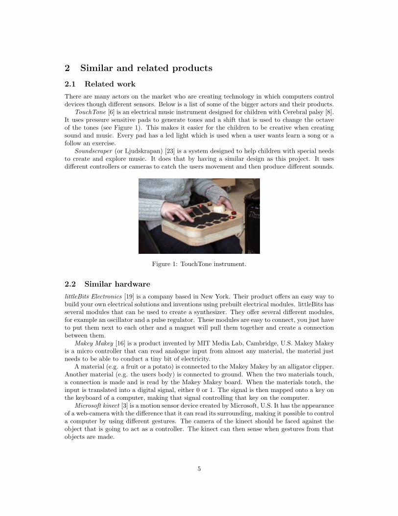
The list of added instruments/controllers is moved to a new single page instead of beingon the main page. This can be seen in the left picture in Figure 5. Also a left swipe functionfor deleting an item was added in the new prototype. There is a ”button activator” setting onthe main page of the old design. This setting is moved to a new page called Settings. This iswhere the user can change certain settings for how the prototype should work. Right now thereis only the ”Button activator” setting, as seen in Figure 5, but in the future there might bemore settings added. When these changes were implemented, a grouping of the button layoutwas introduced. This is described later. The rest of this section will mostly focus on the newprototype design instead of comparing the two designs.
Figure 4: On the left is the first prototype of the main page and on the right is the redesignedprototype.
The new system design tries to be consistent in the way that the layout and buttons aredesigned. Every button that makes the same conceptual action has a similar look. For examplethe buttons that makes the user go back in the application have the same height, length,
11
describing title and position. Also the ”Apply” and ”Back to beginning and reset” buttonshave these properties. The buttons on the main page, see the right picture in Figure 4, aregrouped into small groups. The ”Add instrument” and ”Add custom instrument” buttons aregrouped together on the first row side by side, and are of the same size and have similar iconsand describing titles. They essentially have the same functionality, making it natural to groupthese two buttons together.
The two buttons beneath are ”Added instruments” and ”Settings”. These are harder togroup together since they have different functionalities. However, both have the same conceptualfunction as they change the settings in either an added instrument or some setting for the overallsystem. To show that they still have some uncommon functionalities they are assigned withcompletely different icons and describing texts.
Figure 5: On the left is the page for added instruments and on the right is the page for settings.
These four buttons can also be considered a group since they all have the same size andare grouped like a square. This is intentional since these buttons control all the functions thatchange or add information that is later to be sent to the Arduino.
The ”Upload settings and instruments” button is a group in its own. It has an essentiallydifferent functionality than the other buttons and is only to be used when all the settings areset and it is time to upload data to the Arduino.
The screen that appears when pressing the ”Add instrument” button can be seen in Figure6. On the picture on the left, a controller that generates notes is created if the user presses”Apply”. It is set to receive signals from input 3 on the Arduino chip. On the picture to theright, a fine pitch controller is added. Since the fine pitch only changes the pitch of a tone, weneed to specify which note that should be changed in pitch. This is specified by the different
12

numbers under the ”Output” label, above the ”Apply” button.As an example, you might add a controller that generates notes on input 1. You could then
create a fine pitch controller on input 2 and then specify the output for that controller as 1.Then the system will generate notes from the sensor on input 1, and the sensor on input 2 willchange the pitch on the notes created from the sensor on input 1. This works in the same wayfor the volume and octave controllers.
Figure 6: On the left, a note controller is added. On the right, a pitch controller is added.
The system has two reset/recovery buttons. They can be found in the main page, see theright picture in Figure 4, and in the calibration page seen in Figure 7.
These buttons reset the bluetooth connection and reset all settings to their default values.This function should be useful if the user wants to start from the beginning or if something hasgone wrong (for example if the bluetooth connection is lost or it isn’t able to create a bluetoothconnection).
Some constraints are also added to the system. The user cannot upload an empty list ofinstruments to the Arduino. To be able to add an instrument, the user needs to fill in certainfields (e.g. the name of the instrument and an input needs to be specified). Further, the nameof a controller cannot be longer than 20 characters.
These constraints are presented with an alert message. The alert message presented triesto explain what went wrong and how to recover from it. It does not try to accuse the user ofmaking any faults but rather just informs about what happened and how to solve it.
13

Figure 7: Iphone app design main page.
When an instrument is added, there is a notification on the ”Added instruments” button,showing a number on how many instruments that has been added this far. In this way the usergets feedback on how many instruments they have currently added. When the user presses theupload button, an alert comes up with a loading circle showing the application is busy. Theuser can either wait for it to finish or cancel the action to get back to the main page. When theloading is done the calibration page is shown.
There are also some things worth mentioning regarding the colour schema. The white back-ground and the teal colours of buttons and tables are inspired by the Arduino homepage, whichcan be seen in Figure 8. Jonas Lowgren gives one short principle on how to choose a colourschema: to keep it simple. By that he means that a good design in colours is to choose low-intensity colours and use matching colours [27].
One might argue that the colour schema from the Arduino homepage is kept simple, since ithas has both matching and not very intense colours. The app doesn’t rely on the users abilityto differentiate between colours to be able to use it.
The main colours of the iPhone application are white, teal and blue. When an instrument isadded, a red colour is used. That red colour has a higher brightness value than the teal colourbehind it, making it possible for people with red/green or total colourblindness to differentiatethe change in colour [17]. The different colours of the application have been tested at Vischecks
14

[7] web-page. Each page/view in the application have been tested and verified according toVischecks tests.
The final icon of the application can be seen in Figure 9.
Figure 8: Arduino homepage. 2
Figure 9: Final app icon. 3
2Picture taken from https://www.Arduino.cc3Icon created by artist Jakob Lindh
15

6 Final prototype
The hardware prototype is a grey plastic and metallic box that has several different inputs.There is a USB connection on its right side which is used when connecting it to a computer. Ithas three audio inputs on top, three potentiometers [10] on the front and three potentiometers onthe back. There is a reset button on the left, a ground connection on the left and a light-emittingdiode on the front (showing that it is powered on when lit, and off when not).
Figure 10: Final product.
The three audio inputs in Figure 10 are where the user connects a controller/sensor. In thebeginning, a breadboard and jumper cables were used to connect sensors to the Arduino, butthat requires previous knowledge about how electronics works. The hardware design was laterchanged so that a controller is connected to an audio cable, making it easier to connect sensorsto the prototype. There is a screw that is connected to ground, which a sensor can use if itneeds a ground connection (e.g. the proximity sensor used when developing this prototype).
The potentiometers on the back of the prototype regulate the resistance on the sensors thatare connected on the top. Since some sensors require a high resistance and some low resistance,the potentiometer was added to make it possible to connect a wide range of different sensors.
The potentiometers on the front are static controllers. Their functionality is set in the iPhoneapplication. They function as any other controller that is connected on the top, except that theyare always connected to the prototype. They are added in the same way as any other controller(i.e. by using the iPhone application).
The light-emitting diode on the front is used to show if the system is powered on. If it isemitting light the system is turned on, otherwise it is turned off. The reset button on the leftrestarts the prototype.
16

7 System
When the iPhone application is started the user can only see a button that is labeled connect.This button is used to connect the iPhone via bluetooth to the Arduino bluetooth chip. Boththe Arduino and the chip need to be powered on for the connection to be established.
The Hairless-midiserial software needs to be running and needs to be redirecting all datacoming from the Arduino to a virtual MIDI output port. A music workstation needs to berunning and listening to the port that Hairless-midiserial redirects the MIDI messages to.
7.1 Setup
When a connection is established the user can start adding controllers/instruments. In order toadd a controller/instrument, the user needs to set the input on which the sensor/potentiometeris connected to on the prototype, give it a name and set which type of controller it is (eitherit sends notes, pitch, octave or volume MIDI messages). If the type of the controller is eitherpitch, octave or volume, an output needs to be specified. That output describes which othersensor this sensor should regulate/alter (either volume, pitch or octave).
There is a button on the prototype used for controlling when notes should be played. Thereare three alternatives, listed below.
• Drone: There is always a note playing in the background. This is called drone [9].
• Press: Works like a switch, meaning that when the button is pressed notes are generated,and when the button is pressed again it stops generating notes.
• Hold: When the button is pressed, notes are generated.
7.2 Calibration
When everything is set and all controllers are added, these settings and controllers can beuploaded to the Arduino. When the settings are successfully uploaded, there is a need tocalibrate the sensors that are connected to the prototype. This is due to the sensors givingdifferent analogue values depending on the resistance of the sensors. To start calibrating, theuser presses the calibrate button. When the button is pressed the user gets an alert messagewhich tells the user to set the sensor to a state where its resistance will have a high value.
When the user puts the sensor in a high resistance state and presses the ”ok” button on thescreen, the Arduino reads a value from that sensor and saves it. The same thing is done againbut this time the sensor should be in a low value state.
There is no real need for the user to know when the sensor has a high or low value, only thatit is in an state where it has maximized on minimized output. If the Arduino reads a low valuewhen it expects a high value, the calibration will still work as intended but with the differencebeing that the values from the sensors will be read in an inverted way and the sensor will alsowork in an inverted way, meaning that it will output (from the Arudiono) low values when itactually has a high value.
When all the sensors are calibrated, the user gets an alert message telling everything waseither fine or something went wrong. If everything went fine, the user can start using theprototype after pressing the ”ok” button. However, if something goes wrong, the user needs togo back and start over again.
17

7.3 Running
When everything is setup and calibrated, the user can start generating tones, changing volumes,change the octaves and/or pitch notes depending on controllers/instruments added. The pre-ferred virtual instrument sound that should be generated by the MIDI signals can be set in themusic workstation the user has chosen to use.
18

8 Hardware
Every MIDI message will be generated on the Arduino chip with the help of different sensorsconnected to the chip. The settings for how the sensors are used and when to calibrate thesensors are controlled by the iOS application. The communication between the iOS applicationand the Arduino chip is made via bluetooth low energy (BLE) technology.
8.1 Arduino
Arduino is a micro controller chip with open hardware made for the purpose to be easy-to-use. Itcan be used with Windows, Mac or Linux. This project uses the Arduino UNO model, which has14 digital input/output pins and 6 analogue input/output pins. In this project it was especiallyimportant with the analogue pins because the sensors that are used are analogue sensors.
The chip is powered with either a USB cable or a DC (direct current) connector, withrecommended voltage of 7-12 V. The analogue inputs on the chip take an input voltage from adevice/sensor and convert it to a digital integer value between 0 and 1023. The digital pins canonly read two values, either HIGH (integer value 1) or LOW (integer value 0) [4].
Figure 11: Arduino UNO chip Real caption4
8.2 Bluetooth low energy
This project uses a BLE connection between the iPhone application and the Arduino chip. Sincethere is no bluetooth chip integrated on the Arduino, this project uses the nRF8001 chip[30].BLE is a part of the bluetooth V4.0 protocol. BLE uses less power than regular bluetoothdevices but it cannot exchange as much data as regular bluetooth [29]. BLE is used in thisproject because the iPhone application is only used to send a small amount of data to theArduino UNO.
4Picture taken from https://www.Arduino.cc/en/uploads/Main/ArdGen_UNO.jpg5Picture taken from https://www.adafruit.com/images/970x728/1697-04.jpg
19

Figure 12: nrf8001 BLE chip. 5
8.3 Sensors and similar components
A sensor is an electrical component that can detect changes in the environment and providethat data as an electrical signal. Below is a list of different sensors, or similar components,used in this project. There will not be a detailed description on how they work, only a shorterdescription on how they measure their surroundings.
• Flex sensor: A sensor that measures a bending motion. It outputs different voltagelevels when bent. [26].
Figure 13: Flex sensor. 6
• Potentiometer: It converts either rotary or linear motion into a change of resistance(this is not a sensor, but is used in this project).
6Picture taken from https://cdn.sparkfun.com/datasheets/Sensors/ForceFlexw/FLEX%20SENSOR%20DATA%
20SHEET%202014.pdf
20

Figure 14: Typical potentiometers. 7
• Proximity sensor: A sensor that is able to detect the presence of objects in front of thesensor without any physical contact.
Figure 15: Proximity sensor. 8
• Piezoelectric sensor: A sensor that converts pressure/force into electrical charge.
Figure 16: Piezo sensor. 9
8.4 Development
The development of this product has involved many different components. One part was theiPhone application and this is described in the Design section. Another part has been to solderand connect jumper wires, sensors, potentiometers and other electronics.
7Picture taken from http://sound.westhost.com/pots.htm#markings8Picture taken from https://upload.wikimedia.org/wikipedia/commons/2/27/Sharp_GP2Y0A21YK_IR_
proximity_sensor_cropped.jpg9Picture taken from https://cdn.sparkfun.com//assets/parts/2/9/6/7/09375-1.jpg
21
https://upload.wikimedia.org/wikipedia/commons/2/27/Sharp_GP2Y0A21YK_IR_proximity_sensor_cropped.jpg

Figure 17: During development.
1. The Arduino Uno which is the heart of the ArduInsto.
2. A button used to reset the Arduino.
3. Several potentiometers connected the the Arduino.
4. The Ada Bluefruit chip.
Figure 17 is a picture taken during development when different connections and electronicsstill were being tested. In this picture nothing is soldered together and an breadboard wasused to connect the different components to eachother. Below are some pictures of differentcomponents/sensors used during development.
22

Figure 18: Mini tele connections were later added. This was done so it would be easier to connectsensors to the hardware without having any prior knowledge on how to connect electronics.
Figure 19: Proximity sensor used during testing. This sensor was hard to generate notes on,but it was better at controlling the pitch or volume of notes generated by other sensors.
23

Figure 20: A flex sensor used during testing. This sensor outputs different voltage levels whenbent. In this picture it was used to generate notes. Having a high bent made it generate highnotes, and when not bent it generated low notes.
24
9 Summary
9.1 Performance
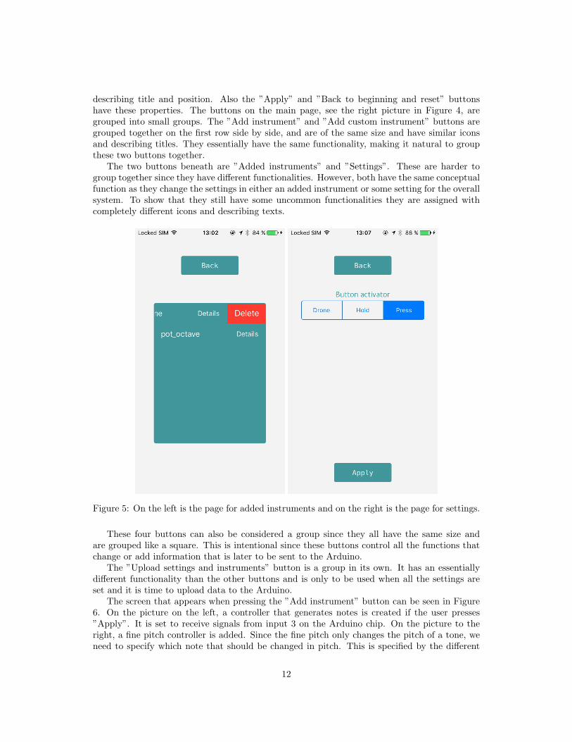
While using the prototype to generate MIDI messages with different controllers, there has beenno substantial lag or slowdowns. The Arduino has enough memory and CPU power to delivergood performance. The limitation of the prototype and Arduino lies in the amount of analogueinputs (i.e. senors) that can be connected. The Arduino UNO device used in this thesis canonly have 6 analogue inputs. There are other versions of the Arduino that have more memoryand more analogue inputs. The downside on the other chips with more inputs is that they aremuch bigger (some are almost double the size of the UNO chip). It has been thoroughly testedwith many different sensors connected to it with different functionalities (for example havinga setup of four sensors where one is generating notes, one changes the pitch, one changes thevolume and the last one changes the octave).
The setup for the whole product can be quite big and cumbersome and this is somethingthat could be done in a better way. For example, if the user tries to upload new settings tothe prototype from the iPhone application, but the upload fails, both the prototype and theHairless midi-serial need to be restarted manually. This should be changed so that it happensautomatically.
Some sensors perform certain tasks better than other. The proximity sensor (distance sensor)is a good controller for tuning fine pitch or volume, but not for generating different notes. Thisis due to the fact that it is so sensitive when reading its surroundings that when it generatesnotes, it changes notes all the time.
The conclusion from a technical point of view is that the Arduino is perfectly capable ofimplementing a device like this. With the added bluetooth connectivity and the iPhone app, ithas a potential to be a practically usable tool at the selected school, but the prototype wouldhighly benefit from having some improvements implemented (those are explained in the nextchapter).
9.2 Conclusion
This thesis aimed to answer the following questions:
• Is it possible to create a small MIDI controller that takes a general analogue control inputand generates the appropriate MIDI signals for a software synthesizer?
• What are the limitations of the Arduino for this kind of application?
I think that it is possible to play and create music using this product. However, in order toconclude how well the product is suited for the creating music, it needs to be tested in futurework. But if we look at the theories of Sergi Jorda and interpret his perspective on digitalinstruments we can come to some conclusions.
In terms of mid-diversity, an instrument can have a big variety of tones and pitches. Thisproduct can have both a low and a high mid-diversity depending on which sensors are usedand what they are set to do. It is possible to have a setup that creates notes from just apotentiometer, and then the instrument would have a low mid-diversity. However, if you set aproximity sensor to control the pitch, a pressure sensor to control the notes and another sensorto control the octave, the user will have a wide range of notes and pitches, giving the instrumenta high mid-diversity.
The macro-diversity defines how the instrument performs in different contexts. Since it usesthe help of a music workstation, it can produce many different sounds using software synthesizers.
25

A problem lies in the way that tones are generated. When using certain sensors to play music,the tones are generated in a linear fashion. This means that one cannot go from a low tone toa high tone without generating the tones in between, when using these particular sensors.
This makes the instrument less generic as it is limited by the way the tones are generated.Although one could use the activation button to generate tones when the activation button ispressed and hold down, to get away from the linearity, but that would lead to a choppy soundwhere the notes are turned on and off all the time. Therefore I think that this prototype has alow macro-diversity.
The product can definitely generate music, but it does this in it’s own way. It is not designedto be a professional instrument, but should rather be regarded as a way of creating music forthe sake of trying something new, or as a way to easily create music or sounds with smallmovements. It does not require the player to be a virtuoso.
9.3 Future work and improvements
The limitations of the Arduino in terms of overall performance was not a problem. The limita-tions of the Arduino version used in this project (the Uno model) were the number of analogueinputs on the board and the size of the board. There are versions of the Arduino that has manymore analogue inputs, but they are also bigger (e.g. Arduino Mega). There are smaller Arduinochips (e.g. Arduino Nano) which run on the same clock speed as the UNO chip and have moreanalogue inputs, but those have much less memory than the UNO[2]. The more analogue inputsthe chip needs to control, the more complex the system will become, thus it might require morememory and a higher clock speed. The Arduino Uno is capable of controlling the 6 analogueinputs with the amount of memory and clock speed it has. It might be interesting to see ifa Nano chip will perform as good, and if it does, if it would be a better chip to use in thisprototype.
Instead of using a laptop to generate the final sound, an idea could be to use a small single-board computer (like the raspberry pi[22]) and to place it inside the box of the prototype.Instead of having to connect the product to a laptop, one would then only need to power upthe product. This would lead to less steps in setting the product up and it would make it moreportable (instead of having to use a laptop/stationary computer together with the product). Itwould require the single-board computer to be controlled from the phone application, or youwould also need to connect a screen with mouse and keyboard.
Other possibilities would be to implement some game like feature in the iPhone app. Thegame could be very simple, maybe letting the player generate certain tones and then gain pointsif the tones are successfully generated. This could be used for different exercises, learning toplay certain songs or just encouraging to use the product.
Testing how well it performs and how easy it is to use for the intended users would be veryuseful for the future of this product. Doing this might give new insights in how to build a systemlike this, and what should be changed in future versions of the product.
One other big improvement would be to develop an application for other platforms, likeAndroid, Windows phones and even Linux and Microsoft Windows. This would make theproduct more accessible since more users would be able to use it.
It would also be very beneficial to be able to improve the bridge between the Arduino andthe music workstation. In this thesis the application Hairless MIDI is used. If the bridgeapplication was built only for this system, it could generate more useful debugging tools, lessoptions in the GUI section and give more control of the whole system to the programmers. Inthis thesis, the Hairless MIDI program was altered in order to generate more useful messagesfor debugging. This could be changed further to improve the relation between the ArduInstoand Hairless MIDI.
26

As briefly noted in the performance section, some sensors perform better than others. Thiscould be fixed by adding a delta mean shift, meaning that every read from a sensor is the meanvalue of a specified number of previous reads and the current read. In this way, the readingfrom some very sensitive sensors may become more stable.
Some improvements can be done in the interface of the iOS application. In Figure 6, theinputs should be numbered from 1-6 instead of 0-5. Also, when adding an instrument that ischanging fine pitch or volume, we need to specify which other controller generating notes itshould modify. Instead of having to choose manually between the different numbered outputs,we would get a list of the current controllers that generate notes and then be able to choose oneof these alternatives.
27
References
[1] K. Anker, Logic Pro X power: The comprehensive guide. Cengage Learning, 2015.
[2] Arduino, Arduino older boards, https://www.arduino.cc/en/Main/Boards, Accessed2016-06-08.
[3] J. Ashley and J. Webb, Beginning Kinect Programming with the Microsoft Kinect SDK.Apress, 2012.
[4] S. F. Barrett, Arduino Microcontroller Processing for Everyone. Morgan & Claypool, 2013.
[5] D. Benyon, Designing Interactive System. Pearson, 2010, vol. 2.
[6] S. Bhat, “Touchtone an electronic musical instrument for children with hemiplegic cere-bral palsy,” in Proceedings of the 4th International Conference on Tangible and EmbeddedInteraction 2010 Cambridge, 2010. doi: DOI:10.1145/1709886.1709955.
[7] D. Bob and W. Alex, Vischeck, http://www.vischeck.com/, Accessed 2015-09-17.
[8] Britannica Academic, Cerebral palsy, http://academic.eb.com.ezproxy.its.uu.se/levels/collegiate/article/22137#, Accessed 2016-12-05, 2016.
[9] ——, Drone, http://academic.eb.com.ezproxy.its.uu.se/levels/collegiate/article/31227#, Accessed 2016-11-07, 2016.
[10] ——, Rheostat, http://academic.eb.com.ezproxy.its.uu.se/levels/collegiate/article/63414#, Accessed 2016-11-07, 2016.
[11] ——, Smarthphone, http://academic.eb.com.ezproxy.its.uu.se/levels/collegiate/article/474140, Accessed 2016-11-07, 2016.
[12] ——, Theremin, http://academic.eb.com.ezproxy.its.uu.se/levels/collegiate/article/72060#, Accessed 2016-11-07, 2011.
[13] ——, Usb, academic.eb.com.ezproxy.its.uu.se/levels/collegiate/article/471630, Accessed 2016-11-28, 2010.
[14] ——, Iphone, http://academic.eb.com.ezproxy.its.uu.se/levels/collegiate/article/443838#, Accessed 2016-11-07, 2016.
[15] W. G. Childs and M. Prager, Reason 7 Power!: The Comprehensive Guide, 1st Edition.Cengage Learning, 2013.
[16] D. Fingal, “Sparkfun electronics; sparkfun to start shipping makey makey kits,” Learning& Leading with Technology, vol. 40, no. 7, 2013.
[17] B. E. Goldstein, Sensation and perception. Wadsworth, 2009, vol. 8.
[18] A. Gratton, The hairless midi to serial bridge, http://projectgus.github.io/hairless-midiserial/, Accessed: 2015-09-20.
[19] W. Greenwald, “Build kid-friendly gadgets with the new littlebits kit,” PC Magazine,pp. 66–70, 2016.
[20] R. Guerin, MIDI Power!: The Comprehensive Guide. Thomson Course Technology, 2006,vol. 2.
[21] R. Guerin and M. Miller, Cubase 5 Power! : The Comprehensive Guide. Cengage Learning,2009.
[22] G. Halfacree and E. Upton, Raspberry Pi user guide. John Wiley & Sons, 2012.
28
[23] K. F. Hansen, C. Dravins, and R. Bresin, “Ljudskrapan/the soundscraper: Sound explo-ration for children with complex needs, accommodating hearing aids and cochlear im-plants,” in SMC Conference 2011, 2011.
[24] T. M. Howard, Garageband ’08 Power. Cengage Learning, 2008.
[25] S. Jorda, “Digital instruments and players: Part II-diversity,” in Freedom and Control.International Computer Music Conference, 2005.
[26] W Justin, Flex sensor data sheet, Spectrasymbol, 2014.
[27] J. Lowgren, Human-computer interaction. Studentlitteratur, 1993.
[28] Medea, “Arduino FAQ – With David Cuartielles,” Prototyping Futures, pp. 53–54, 2012.
[29] S. C. A. Mobile and N. Council, “Bluetooth low energy (ble) 101: A technology primerwith example use cases,” Smart Card Alliance, Tech. Rep., 2014.
[30] Nordic Semiconductor, Nrf8001 product specification 1.3, Nordic SemiConductor, 2015.
[31] M. M. R. Perry, “Relating improvisational music therapy with severely and multiplydisabled children to communication development,” Journal of Music Therapy, pp. 227–244, 2003. doi: 10.1093/jmt/40.3.227.
[32] M. Spiegelmock, Leap Motion development essentials. Packt Publishing, 2013.
[33] S. Susan and Y. Sanna, “Effect of music therapy on children with disabilities,” Proceedingsof ICMPC8, pp. 341–343, 2004.
[34] T. Torres, “Control your pc with arm gesturessort of.,” PC Magazine, pp. 60–64, 2015.
[35] Uppsala University, Mumin-projektet, http : / / www . it . uu . se / research / visual _
information_and_interaction/research/MUMIn?lang=sv, Accessed: 2016-05-05, Up-dated: 2016-02-29, 2015.
29


![USB MIDI/LTC Widget MIDI LTC... · USB MIDI/LTC Widget 1.783 [45.28] 7.808 [198.33] Timecode- Single Linear Input Connection- USB-B (1) MIDI-Input-Supports- MIDI MIDI Show Control](https://static.fdocuments.in/doc/165x107/5f8814d97ac2ab28ba5b1540/usb-midiltc-widget-midi-ltc-usb-midiltc-widget-1783-4528-7808-19833.jpg)