Reference Architecture for Service Oriented Architecture ...
Upload
nguyenthuyCategory
view
215download
0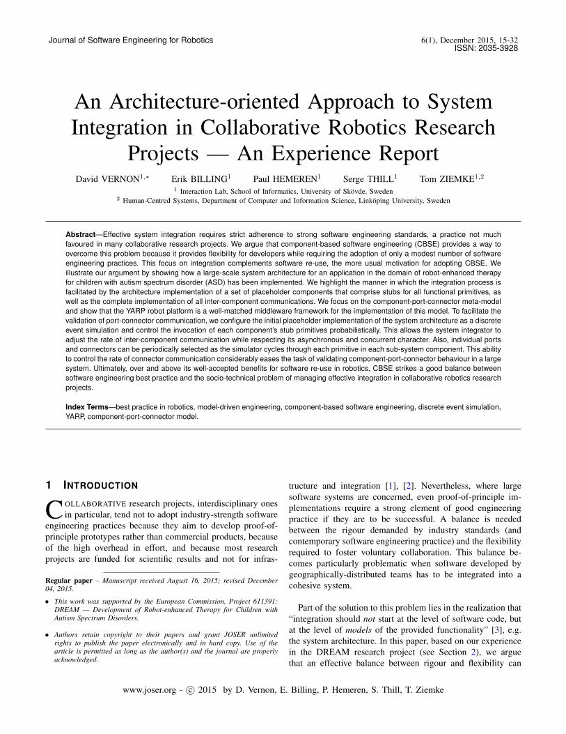
Journal of Software Engineering for Robotics 6(1), December 2015, 15-32ISSN: 2035-3928
An Architecture-oriented Approach to SystemIntegration in Collaborative Robotics Research
Projects — An Experience ReportDavid VERNON1,∗ Erik BILLING1 Paul HEMEREN1 Serge THILL1 Tom ZIEMKE1,2
1 Interaction Lab, School of Informatics, University of Skovde, Sweden2 Human-Centred Systems, Department of Computer and Information Science, Linkoping University, Sweden
Abstract—Effective system integration requires strict adherence to strong software engineering standards, a practice not muchfavoured in many collaborative research projects. We argue that component-based software engineering (CBSE) provides a way toovercome this problem because it provides flexibility for developers while requiring the adoption of only a modest number of softwareengineering practices. This focus on integration complements software re-use, the more usual motivation for adopting CBSE. Weillustrate our argument by showing how a large-scale system architecture for an application in the domain of robot-enhanced therapyfor children with autism spectrum disorder (ASD) has been implemented. We highlight the manner in which the integration process isfacilitated by the architecture implementation of a set of placeholder components that comprise stubs for all functional primitives, aswell as the complete implementation of all inter-component communications. We focus on the component-port-connector meta-modeland show that the YARP robot platform is a well-matched middleware framework for the implementation of this model. To facilitate thevalidation of port-connector communication, we configure the initial placeholder implementation of the system architecture as a discreteevent simulation and control the invocation of each component’s stub primitives probabilistically. This allows the system integrator toadjust the rate of inter-component communication while respecting its asynchronous and concurrent character. Also, individual portsand connectors can be periodically selected as the simulator cycles through each primitive in each sub-system component. This abilityto control the rate of connector communication considerably eases the task of validating component-port-connector behaviour in a largesystem. Ultimately, over and above its well-accepted benefits for software re-use in robotics, CBSE strikes a good balance betweensoftware engineering best practice and the socio-technical problem of managing effective integration in collaborative robotics researchprojects.
Index Terms—best practice in robotics, model-driven engineering, component-based software engineering, discrete event simulation,YARP, component-port-connector model.
1 INTRODUCTION
C OLLABORATIVE research projects, interdisciplinary onesin particular, tend not to adopt industry-strength software
engineering practices because they aim to develop proof-of-principle prototypes rather than commercial products, becauseof the high overhead in effort, and because most researchprojects are funded for scientific results and not for infras-
Regular paper – Manuscript received August 16, 2015; revised December04, 2015.
• This work was supported by the European Commission, Project 611391:DREAM — Development of Robot-enhanced Therapy for Children withAutism Spectrum Disorders.
• Authors retain copyright to their papers and grant JOSER unlimitedrights to publish the paper electronically and in hard copy. Use of thearticle is permitted as long as the author(s) and the journal are properlyacknowledged.
tructure and integration [1], [2]. Nevertheless, where largesoftware systems are concerned, even proof-of-principle im-plementations require a strong element of good engineeringpractice if they are to be successful. A balance is neededbetween the rigour demanded by industry standards (andcontemporary software engineering practice) and the flexibilityrequired to foster voluntary collaboration. This balance be-comes particularly problematic when software developed bygeographically-distributed teams has to be integrated into acohesive system.
Part of the solution to this problem lies in the realization that“integration should not start at the level of software code, butat the level of models of the provided functionality” [3], e.g.the system architecture. In this paper, based on our experiencein the DREAM research project (see Section 2), we arguethat an effective balance between rigour and flexibility can
www.joser.org - c© 2015 by D. Vernon, E. Billing, P. Hemeren, S. Thill, T. Ziemke

16 Journal of Software Engineering for Robotics 6(1), December 2015
be struck by taking an operational-architecture1 approach tosystem integration and adopting component-based softwareengineering (CBSE) [4], [5], [6], [7]. While CBSE is normallyexploited to promote greater software re-use, here we wishto highlight the advantages it offers for system integration,realized through its focus on component composability.
The other part of the solution to the problem of achievingthe right balance lies a second realization that integration isa socio-technical issue concerned with project managementin circumstances involving independently-minded researchersthat are not always inclined to adopt extensive strict standards.CBSE offers something much better than a least-worst res-olution of this project management and software integrationdilemma: sound engineering practice with minimal overheadwhile affording considerable flexibility for the developer.
Thus, the main purpose of this article is not to proposea particular architecture nor even a tool for designing anarchitecture, but a methodology that makes the process ofsoftware development and subsequent integration more effec-tive and efficient in collaborative research projects. It is wellacknowledged that any large system requires an architectureto be designed first and that this architecture drives thesubsequent software design and development process. Ourcentral point is that this architecture can be operational firstand that by so doing it becomes a driver for the softwaredevelopment of each constituent sub-system. This facilitatesintegration by providing hard constraints on the outcome ofthe software sub-system development without the impositionof hard constraints on all the other phases of the softwaresub-system development lifecycle. Thus, the contribution ofthe paper is primarily methodological, with support for thatmethodology being provided by a discrete event simulationtechnique to facilitate handling the complexity of integrationthat naturally arises from a complete implementation of the fullsystem architecture and the large number of associated inter-sub-system communications. It is a relatively straightforwardapproach that provides clear integration acceptance criteria,substantially easing the burden on the developers withoutcompromising the integration process. This results in a win-win situation for the developers and the system integrator.
Having said that, software development and integration doesnot take place in a vacuum and the implemented operationalarchitecture, considered as a driver for both sub-system de-velopment and integration, is not sufficient by itself. Thereare two other key elements: the user requirements and systemspecification that define the software functionality, and thesoftware engineering process by which the required softwareis developed.
1. The phrase operational architecture is sometimes used to refer to a wayof structuring complex operations, often in the military domain where it is oneof three views on the enterprise architecture. However, in this paper we useit in a different way: to emphasize that the architecture itself is realised as aworking system of interacting components, each of which acts as a placeholderfor software that is subsequently integrated.
We deal with the system specification and its encapsulationin the system architecture in Section 6, highlighting its ground-ing in requirements derived from use cases in order to ensurethat the inter-sub-system interfaces capture the semantics ofthe information exchanged.
We deal with the software standards in Section 7. Here it isimportant to note that the processes of both software develop-ment and integration are governed by standards covering thefull development lifecycle. These standards form the essentialbackdrop for the software development and integration effort.It is significant that the approach advocated in the paper allowstwo classes of standards to be adopted: mandatory standardsand recommended standards. The mandatory standards relateto those aspects of the software that refer to integration whilethe recommended standards relate to everything necessaryfor that sub-system to achieve the required functionality.2
Significantly, each team of developers responsible for thethree functional architecture sub-system components has de-veloped their own specific sub-system architecture using theirown preferred modeling, specification, design, implementa-tion, and test practices. The only constraints on their sub-system architecture design derive from the standards imposedby mandatory standards. How they achieve this is completelyup to them. Although the recommended standards do providesome advice, the developers are under no obligation to takeit. This is the win-win that derives from the operational-architecture approach described in the paper: freedom to adoptor not industrial-strength standards governing the full softwaredevelopment life-cycle and unproblematic integration providedthey adhere to the mandatory standards.
Within the broad domain of CBSE, we focus in particularon the component-port-connector (CPC) meta-model, i.e, leveltwo of the Object Management Group’s (OMG) four-levels ofabstraction in model-driven engineering (MDE) [8]. Effectiveimplementation of the CPC meta-model imposes a minimalnumber of necessary software engineering practices. We showhow one specific development platform, YARP [9], [10],provides a suitable middleware framework to support thesepractices. The operational-architecture approach suggestedhere provides additional flexibility for developers by onlyspecifying the architecture at the sub-system levels, allowingeach sub-system to then take advantage of the emergent archi-tecture approach [2], allowing the sub-system to be developedas required without compromising the standards required foreffective integration.
We demonstate the approach by showing how the sys-
2. As we will see in Section 4, the mandatory standards relating to thoseaspects of the software that refer to integration, i.e. the standards imposed bysystem architecture component specification, correspond to three of the fourCs of component-based software engineering: coordination, configuration,and communication. The recommended standards relate to the fourth C:computation, i.e. everything necessary for that sub-system to achieve therequired functionality and cover the full software development lifecycle. Someminimal mandatory standards were in fact adopted for computation but theserelated only to the manner in which the functionality is encapsulated.
D. Vernon et al./ An Architecture-oriented Approach to System Integration 17
tem architecture for a humanoid robotics application in thedomain of robot-enhanced therapy for children with autismspectrum disorder (ASD) has been implemented. In particular,we highlight the advantage of the component-based approachfor system integration by realizing the complete system ar-chitecture as four stub-driver sub-systems implemented asfour distinct placeholder components. These four componentsrealize all the communciation ports and connectors for thecomplete system. Since the number of ports and connectorsis large (of the order of one hundred in either case), it is nottrivial to ensure that communication over all these connectorsis working correctly, especially because all communciationtakes place asynchronously and concurrently. On the otherhand, once it has been established that inter-component com-munication is working effectively, subsequent integration offunctional software is made much easier when replacing stuband driver primitives with the operational primitives. To solvethe problem of validating all inter-component communication,we implement the system architecture as a discrete eventsimulation and control the invocation of each component driverprobabilistically. This allows the system integrator to adjustthe rate of inter-component communication during integrationwhile not violating its asynchronous and concurrent character.Furthermore, individual ports and connectors can be periodi-cally selected as the simulator cycles through each primitivein each sub-system component. This ability to control the con-nector communication considerably eases the task of validatingcomponent-port-connector behaviour.
2 THE DREAM PROJECT
DREAM [11] is a 41/2-year European project in whichseven partners are involved in developing software for robot-enhanced therapy for children with ASD. Social robots —specifically the Nao [12] and Probo [13] robots — are used astools to help these children develop imitation, joint attentionand turn-taking skills, with the final objective of achievingbetter real-life human-human social interaction.
Researchers have found that the use of technological toolsimproves the acquisition of social skills in children with ASD[12], [13], [14], [15]. In particular, robots might have thepotential to act as intermediaries between human therapistsand patients (see [16]). There are three ways for this to beaccomplished: the robo-therapist, the robo-assistant, and therobo-mediator approaches. In the robo-therapist approach, therobot acts by itself as the therapist and completely replaces thehuman agent. In the robo-assistant approach, the robot acts asa facilitator of the therapy intervention but is not necessary forsuccessful treatment and could be replaced by another agent,e.g., an animal. In the robo-mediator approach, the robot isused as a means for delivering the treatment because it enablesfaster and better gains from the therapeutic intervention.
DREAM constitutes an extension of the robo-mediatorapproach (often referred to has robot-assisted therapy or RAT)
in which the robot is a necessary component of the therapy,forming a third element in the therapy intervention alongsidethe child and the therapist, but the robot has greater autonomyin conducting the intervention [17]. The robot’s behaviour isstill supervised by the therapist and, consequently, it exhibitsa form of autonomy referred to as supervised or sharedautonomy. We refer to this next-generation RAT as robot-enhanced therapy or RET. To achieve this level of autonomy,while following the intervention script, the robot must beable to (a) gather sensory data about the child, (b) assesspsychological disposition and behaviour, and (c) adjust itsactions accordingly when mediating the therapy intervention.Consequently, the robot software has three main sub-systems,one for sensing and interpretation of perceptual data, one foranalysis of child behaviour, and a third for controlling thebehaviour of the robot. The graphic user interface constitutesa fourth component.
One of our tasks in DREAM is to realize the robotsoftware by integrating the individual contributions of fivegeographically-distributed teams of developers. The goal ofthis paper is to show how this task is facilitated by theadoption of CBSE, in general, and CPC, in particular. Inthe following, we summarize the main features of CBSEand CPC, and identify the associated software engineeringpractices that make this a suitable approach for the designand implementation of the DREAM robot software system.We then follow this with a description of our experience inputting these into effect in the implementation of the DREAMsoftware architecture using placeholder components, focussingin particular on the merits this has for subsequent integrationof the functional elements of the architecture.
3 COMPONENT-BASED SOFTWAREENGINEERINGCBSE targets the development of reusable software [18] andhas been widely adopted in the robotics community [19].It complements traditional object-oriented programming byfocussing on run-time composition of software rather thanlink-time composition. Consequently, it allows different pro-gramming languages, operating systems, and possibly com-munication middleware to be used in a given application.Related to the classic concept of communicating sequentialprocesses (CSP) [20], components are individually-instantiatedprocesses that communicate with each other by message-passing. Typically, component models assume asynchronousmessage-passing where the communicating component is non-blocking, whereas CSP assumed synchronous communication.The key idea is that components can act as reusable buildingblocks and that applications and system architectures can bedesigned by composing components. This gives rise to thetwo key concerns of component-based models: composability(the property of a component to be easily integrated into alarger system, i.e. to be reused under composition) and com-positionality (the property of a system to exhibit predictable
18 Journal of Software Engineering for Robotics 6(1), December 2015
Fig. 1. The 5 Cs of the BRICS component model: the coreidea is that good component-based engineering practice strivesto decouple the design concerns of these five functions (from[21]).
performance and behaviour if the performance and behaviourof the components are known) [21].
In complex robotics systems, as in other large softwaresystems, integration is difficult. It is made easier by adoptingpractices that support composability and compositionality. AsBruyninckx notes, composability and compositionality are notindependent and “achieving full compositionality and compos-ability is an ideal that is probably impossible to achieve” [22]because the information hiding characteristic inherent in goodcomponent design conflicts with the transparency required bysystem builders to optimize system robustness by selectingcomponents whose internal design is such that it can copewith as many system variations as possible.
Although they share some common principles, CBSE andobject-oriented approaches are not identical. Typically, thegranularity of components in CBSE is larger than that ofobjects in object-oriented approaches. Thus, the functionalityencapsulated in a component is usually greater than that of anobject. Also, components are explicitly intended to be stand-alone independently-executable reusable pieces of softwarewith well-defined public interfaces.
On the other hand, in CBSE, as in object-oriented program-ming, the component specification is separated from the com-ponent implementation. A component exposes its functionalitythrough abstract interfaces that hide the underlying imple-mentation. Thus, the implementation can be altered withoutaffecting any of the systems or other components that use (i.e.interface with) that component. Components exchange datathrough their interface.
In robotics, a component implements a well-encapulatedelement of robot functionality and robot software systemsare constructed by connecting components [6], [7]. The con-nections are often, but not necessarily made using ports inthe components. As we will see below, this echoes the keyelements of the CPC model.
4 CPC AND THE BRICS COMPONENTMODELFocussing on the issues that are particularly important indeveloping robot software, the BRICS Component Model
(BCM) [21], [23], [24] is a best-practice CBSE model thatprovides a set of principles, guidelines, meta-models, andtools for structuring the development of individual componentsand component-based systems. It does so in a framework-nonspecific manner, i.e. at an abstract (meta) level that doesnot refer explicitly to the implementation of the requiredfunctionality on a specific robot platform.
BCM brings together two strands of software engineering:the separation of the so-called 4Cs of communication, com-putation, configuration and coordination [25] and robotics-oriented MDE [26]. BCM extends the 4Cs to 5Cs [3] by split-ting configuration into finer-grained concepts of configurationand composition (see Fig. 1). The core principle is that goodcomponent-based engineering practice strives to decouple thedesign and implementation of these five concerns.
Computation refers to the system’s main functionality, i.e.the information processing the component has been designedto perform. Communication provides the data required bythe computation and takes care of the quality of service ofdata communication, e.g. timing, bandwith, loss (accuracy),priority, and latency. Coordination refers to the functionalitythat determines how all the components in a system worktogether and, thus, how the component or system behaves.Configuration refers to the functional aspects concerned withinfluencing the behaviour of the computation and commu-nication elements either at start-up or at run-time. Finally,composition, the fifth C introduced in [21], provides the gluethat binds together the other four Cs, each of which is focussedon decoupling functionality. In contrast, composition is verymuch concerned with coupling: how the other four Cs interact.Strictly, this C does not reflect software functionality but israther a design characteristic that seeks to find a good trade-off between composability and compositionality [3].
Complementing CBSE, MDE aims to improve the processof code generation from abstract models that describe adomain. The OMG [8] defines four levels of model abstraction,going from higher to lower levels of domain specificity (i.e.from platform-independent to platform-specific) by addingplatform knowledge. These four levels can be characterizedas follows [21].
M3 Domain-nonspecific: the highest level of abstractionusing a meta-meta-model.
M2 Platform-independent representation of a domain, us-ing, e.g., a Component-Port-Connector (CPC) meta-model.
M1 Platform-specific model: a concrete model of a spe-cific robotic system but without using a specificprogramming language.
M0 The implementation level of a specific robotic sys-tem, with defined software frameworks, libraries, andprogramming languages.
Level M2 is of particular interest here because the abstractmodel, i.e. the CPC meta-model, maps directly to the prin-ciples of component-based software engineering. The essence
D. Vernon et al./ An Architecture-oriented Approach to System Integration 19
of this model is as follows [21]. An application system haszero or more components and zero or more connectors. Acomponent has zero or more ports, and a port belongs to oneand only one component. A connector is always between twoports. Finally, and of particular importance in the context of thecurrent discussion, components expose their data and serviceinterfaces on their ports and exchange data over the attachedconnectors.
The principles of CBSE have another important role in thatthey also constrain the selection of a software environmentthat will be used to provide the abstraction layer between theapplication code, on the one hand, and the middleware andoperating system services (including support of distributedsystems processing and device input/output), on the other.This abstraction layer is typically provided by the robotprogramming framework. It provides an abstract interfacebetween the robot software system (implemented as a networkof components) and the underlying operating system andmiddleware.
The CBSE CPC approach offers several advantages inconfiguring robotics applications. The robot application canbe implemented simply by identifying the components tobe instantiated and specifying the connections between theirport interfaces. Each component can encapsulate some coarse-grained robot functionality, i.e. the component can performsome substantial function while maintaining its cohesion. Itis possible to have multiple instances of the same componentby having a mechanism for uniquely naming each instance ofthe component and propagating that name to the component’sport names. A key characteristic is the support for externalconfiguration of the component allowing the behaviour ofindividual instances of a component to be customized bythe application developer without recourse to the componentdeveloper. This goes hand in hand with a facility to allowcomponents to run in different contexts, meaning that the robotprogramming framework allows the component user to specifythe location of the components configuration files and otherresources. Runtime configuration of the behaviour of the com-ponent can be provided to allow users and other components tocontrol the component’s processing, if required. In many robotprogramming frameworks, e.g. YARP, components run asyn-chronously on a distributed system with the inter-componentcommunication over ports being handled transparently by therobot programming framework. This means that the logicaldefinition of a component-based application is independentfrom its run-time configuration and the ports provide abstractcomponent interfaces. This communication infrastructure mayprovide multiple transport layer protocols, e.g. udp, tcp, andmcast.
What is significant about this is that adopting the CBSECPC approach imposes a minimal number of required con-figuration practices on the component developer. Specifically,these are to support:
1) Unique naming of each instance of a component and
propagation of that name to the port names;2) Renaming any of the ports through which the interfaces
are exposed;3) External configuration of the component behaviour;4) External specification of the context (i.e. path) to search
for the associated configuration files;5) Run-time configuration of the component behaviour
reading parameter values from a port.Clearly, the underlying robot programming framework is piv-otal in supporting these practices and making them straightfor-ward for the component developer to implement. We considerthis issue in the next section.
5 ROBOT PROGRAMMING FRAMEWORK
There are many robot programming frameworks. These in-clude ROS [27], YARP [9], URBI [28], and Orca [29], [30].All have their respective advantages and disadvantages, asexplained in various surveys and comparisons [31], [32]. ROS,a popular choice in many instances, has been criticized inthe context of CBSE as lacking an abstract component model[26]. On the other hand, while YARP does not have anabstract component model either, it provides a framework thatexplicitly supports all the CBSE needs identified above. Weprovide examples of the manner in which it does so in thefollowing. Note that our adoption of YARP does not mean itis the only framework that can support the approach describedin this paper; other frameworks, including ROS, would alsobe viable.
YARP was designed to support the CPC meta-model as wellas the principles of CBSE and the principles of model-drivenengineering. A YARP module corresponds to a componentand it can have an arbitrary number of ports, with modulesbeing connected by specifying the ports on either side ofa connection. YARP supports the implementation of robotapplications by identifying the components to be instantiatedand specifying the connections between their port interfaces.As we will see below, YARP also provides considerablesupport for component development.
YARP supports coordination and configuration with theRFModule and ResourceFinder classes. It supports externalconfiguration of the behaviour of the component throughthe use of configuration files. This allows the behaviourof individual instances of a component to be customizedby the application developer or system integrator withoutrecourse to the component developer. It is the responsibilityof the component developer to expose all these parametersto the user. YARP provides the component developer withthe ResourceFinder class that provides methods to readand parse key-value parameters either from the configurationfile or from the arguments associated with a command-lineinvocation of that module. If key-value arguments are suppliedin the configuration file and in the command-line invocation,the latter takes precedence. YARP supports coordination, i.e.
20 Journal of Software Engineering for Robotics 6(1), December 2015
external control of component behaviour, through runtimeconfiguration, by allowing commands to be issued on a specialport with the same name as the component and by providing adedicated RFModule method respond to handled input. Thesecommands will typically alter the parameter values whilethe component is executing. The port can be used by othercomponents and also interactively by a user through the YARPrpc directive. Parsing these parameter update commands isalso handled by a utility method in the ResourceFinder
class.The functional aspect of the code — computation — is
separated by localizing all functionality in a method derivedfrom either the Thread class or the RateThread classes.
All communication with other components is effectedthrough YARP ports. These are opened and closed duringthe configuration phase before the computation thread isinstantiated and are passed as arguments to the thread.
YARP also provides a facility to allow components to runin different contexts. This means that it allows the componentuser to specify the location of the component’s configurationfiles and other resources.
All YARP modules run and communicate asynchronouslyand YARP supports distributed computing allowing an appli-cation developer as well as a component developer to assigna component to a given run-server. It is straightforward to runcomponents on a network of computers, be it a distributedsystem, a collection of PCs, or a server farm. It supports aflexible communication infrastructure with multiple transportlayer protocols so that the ports can be configured to usedifferent communication protocols and carriers, such as tcp,udp, mcast (multi-cast) with several variants of each.
6 DREAM SYSTEM ARCHITECTUREHaving laid the foundations with the CPC meta-model andthe YARP robot programming framework, we are now in aposition to describe the DREAM system architecture and itsrealization as an operational system that facilitates managedincremental integration of functional software.
System architectures in general, and cognitive architecturesfor robots in particular, are used as blueprints for the func-tional, structural, and behavioural specification of a completesystem [33], [34], [35]. Typically, this specification is effectedat quite a high level of abstraction and not at a level that issufficient to address all the design decisions required beforeembarking on an implementation of the requisite functionality.However, because we are using CBSE in the form of theCPC meta-model, our specification of the DREAM systemarchitecture can be rendered in terms that do allow it to bemapped directly to an implementation. This is accomplishedby identifying the functionality of each major sub-systemin terms of a suite of abstract functional primitives and theports through which these primitives expose their abstractinterfaces. Each sub-system can then be viewed as a macro-scopic component with a well-defined set of ports. The system
architecture then is completed by specifying the connectors,i.e. the interconnections between the ports associated with eachsub-system component.
It is important to note here that these primitives representa system specification that is grounded in user requirementsderived from detailed use cases. This ensures that theinter-sub-system interfaces capture the semantics of theinformation exchanged and not just the syntax of theexchange protocol. The use cases define the interventionsto be carried out between child, therapist, and robot.These were generated by developing a series of child-robotinteraction scripts describing detailed scenarios for the threetypes of intervention being addressed: (a) joint attention,(b) imitation, and (c) turn-taking. The interventions weredecomposed into nine tasks. For each task, we set out adetailed breakdown of the associated actions, componentmovements and sensory cues, and the associated sensory-motor processes. The sensory-motor processes providethe essential input for the definition of robot behaviourspecification, i.e. the associated robot behaviours that haveto be implemented to conduct all the intervention tasks,and the child behaviour specification, i.e. the expected childactions that have to be monitored. The robot behaviours areexpressed in terms of six parameterized action primitives, e.g.moveHead (x, y, z), and one vocal expression primitive.The child’s actions are described in perceptual terms,from the perspective of the robot, as perception primitivesthat can be used to determine the child’s behaviour, e.g.identifyFaceExpression(x, y, z, expression_id)
or getEyeGaze(x, y, z); see Table 1. While the translationfrom use case to primitive did not exploit a formal modelof requirement elicitation, the resulting primitives, andtheir encapsulation in the port interfaces, ensure that thecomponent-port-component communication in the operationalsystem architecture embrace both the syntax and the semanticsof the information exchange.
The implementation of the system architecture then be-comes an exercise in developing and validating a placeholdercomponent for each sub-system in the architecture, with eachsub-system component emulating its constituent functionalprimitives and reading/writing the related data from/to therelevant ports. Thus, the complete system architecture is im-plemented first as a set of placeholder components comprisingstubs for all perception and action primitives in each sub-system together with a complete implementation of the full setof port interfaces used by these stub primitives. Functionalityis added as individual components are progressively integratedby allowing them to take over communication on the portsused by the stubs.
By adapting this operational-architecture implementation,we strike a balance between allowing the eventual builder ofthe individual primitive components the freedom to focus onalgorithms and component functionality, on the one hand, andproviding the necessary constraints on component interfaces

D. Vernon et al./ An Architecture-oriented Approach to System Integration 21
to ensure successful integration, i.e. compositionality, on theother. Each of these individual components must adhere tothe strictly-defined interface semantics encapsulated in theplaceholder port specification and implementation, exactly asadvocated by Schlegel [36]. While we have not explicitly usedSchlegel’s set of five generic communication patterns, theyare implicitly embraced by the YARP port communicationprotocols that implement the component interfaces.
Validation of the system architecture takes the form of en-suring that all the port interfaces and connectors are operatingcorrectly. Since the number of ports and connectors can belarge (127 and 76, respectively, in the case of the DREAMsystem architecture) this validation exercise can be non-trivial.This is because, with all components communicating asyn-chronously on all ports simultanously, it is difficult to monitorthe behaviour of sender and receiver components and verifythat communications have been sent and received correctly.We return to this issue later when we describe an approachbased on discrete event simulation to model the invocation ofeach primitive stub in a controlled manner.
6.1 Architecture OverviewThe core of the DREAM RET robot is its cognitive modelwhich interprets sensory data (e.g. body movement and emo-tion appearance cues), uses these percepts to assess the child’sbehaviour by learning to map them to therapist-specifiedbehavioural classes, and learns to map these child behavioursto appropriate therapist-specified robot actions. Thus, theDREAM system architecture has three major functional sub-systems:
1) Sensing and Interpretation,2) Child Behaviour Analysis, and3) Robot Behaviour.
These sub-systems are implemented by three components,sensoryInterpretation, childBehaviourClassification, and cog-nitiveControl, respectively. The functional specifications ofthese three sub-systems are derived directly from the threetypes of intervention mentioned above (imitation, joint atten-tion, and turn taking). These interventions are described asa sequence of actions, each action comprising a number ofconstituent movements and sensory cues linked to a particularsensory-motor process. The motor aspect of these processesprovides the basis for the robot behaviour specification to beimplemented in the cognitive control sub-system. The sensoryaspect provides the basis for the sensory interpretation sub-systems and also the child behaviour classification sub-system.
A walk-through of these interventions yielded a set oftwenty-five sensory interpretation primitives, three child clas-sification primitives, and seven cognitive control primitives.Each primitive will eventually be implemented as a dis-tinct component in the DREAM architecture. However, forthe purpose of implementation and validation of the systemarchitecture, it is sufficient to group them together in the
Primitive Input Parameters Output Parameters
sensoryInterpretation
checkMutualGaze returns true or falsegetArmAngle left_h,v,right_h,vgetBody x, y, zgetBodyPose <joint_i>getEyeGaze eye x,y,zgetEyes left_x,y,z,right_x,y,zgetFaces <x,y,z>getGripLocation object_x,y,z grip_x,y,zgetHands <x,y,z>getHead x,y,zgetHeadGaze x,y,zgetHeadGaze x1,y1,z1,x2,y2,z2,x3,y3,z3 x,y,zgetObjects <x,y,z>getObjects centre_x,y,z,radius <x,y,z>getObjectTableDistance object_x,y,z vertical_distancegetSoundDirection threshold azimuth, elevationidentifyFace x,y,z face_ididentifyFaceExpression x,y,z expression_ididentifyObject x,y,z object_ididentifyTrajectory <x,y,z,t> trajectory_descriptoridentifyVoice voice_descriptorrecognizeSpeech texttrackFace seed_x,y,z,time_interval projected_x,y,ztrackHand seed_x,y,z,time_interval projected_x,y,ztrackObject seed_x,y,z,time_interval projected_x,y,z
childBehaviourClassification
getChildBehaviour <state, probability>getChildMotivation engagement, confidencegetChildPerformance performance, confidence
cognitiveControl
grip statemoveHand handDescriptor,x,y,z,rollmoveHead x,y,zmoveSequence sequenceDescriptormoveTorso x,y,zsay text, toneenableRobot stategetInterventionState id, state, cogMode
TABLE 1The primitives provided by the three sub-system placeholdercomponents. The input and output parameters are exposed
through the matching ports, e.g./sensoryInterpretation/getEyeGaze:i and/sensoryInterpretation/getEyeGaze:o.
three sub-system placeholder components. These primitivesare listed in Table 1. The input and output ports that areexposed by each primitive component and through which inputand output data can be exchanged with these sub-systems(and, eventually, with the individual components that willencapsulate each primitive and replace the sub-system stubs)are also listed in Fig. 1. The parameters of each primitivein the three sub-systems are exposed by two dedicated ports,one for input and one for output, with the arguments en-capsulated in a YARP vector or bottle,3 whichever is moreappropriate. The general naming convention for the two portsis to use the primitive name as the root of the port name,appending :i or :o, depending on whether it is an inputor an output port, i.e. /<primitive name>:i for input and/<primitive name>:o for output. It only remains then tospecify the connectors between the ports to define the sub-
3. YARP has a variety of methods to support abstraction in data representa-tion, including the Bottle class. This is a simple collection of objects that canbe described and transmitted in a portable way. This class has a well-defined,documented representation in both binary and text form. Objects are storedin a list, which you can add to and access.
22 Journal of Software Engineering for Robotics 6(1), December 2015
system interconnectivity and complete the specification ofthe DREAM system architecture, which we will do in thefollowing sections. First we will expand on the functionalspecification of the three sub-system placeholder components.
6.2 The sensoryInterpretation ComponentThe functionality of sensoryInterpretation is specified by thetwenty-five perception primitives and associated input and out-put ports in Table 1. Not all primitives have input parameters.The components for those that do are stateful, i.e. once theassociated argument values are set, they remain persistently inthat state until reset by another input.
6.3 The childBehaviourClassification ComponentThe getChildBehaviour() primitive classifies the child’sbehaviour on the basis of current percepts. It produces a set ofnumber pairs where the first element of each pair representsa child state and the second element the likelihood that thechild is in that state. Thus, the primitive effectively producesa discrete probability distribution across the space of childstates.
The getChildMotivation() primitive determines thedegree of motivation and engagement on the basis of thetemporal sequence of child behaviour states, quantifying theextent the children are motivated to participate in the taskswith the robot and detect in particular when their attention islost. It produces two numbers, the first representing an estimateof the degree of engagement and the second representing anindication of confidence in that estimate.
The getChildPerformance() primitive determines thedegree of performance of the child on the basis of a temporalsequence of child behaviour states, quantifying the perfor-mance of the children in the therapeutic sessions. It producestwo numbers, the first representing an estimate of the degreeof performance and the second representing an indication ofconfidence in that estimate.
6.4 The cognitiveControl ComponentThe functionality of the cognitiveControl component is spec-ified partially by the first seven action primitives listed inTable 1. This is only a partial specification because the basisfor invoking each of these action primitives cannot be fullydefined (whereas, in the case of sensoryInterpretation, all ofthe primitives are continually invoked to monitor the statusof the robot’s environment). Specifically, these seven actionprimitives only reflect the functionality needed to carry outthe robot behaviours to follow the scripted interventions thatare encapsulated in the use cases. However, by itself this is notsufficient because there are two additional considerations foreffective robot control in the context of supervised or sharedautonomy.
First, the robot control is focussed on interaction withthe child. Even when everything goes according to plan and
the intervention scripts can be followed exactly, there is aneed to adapt the robot behaviour to ensure its actions aresynchronized with those of the child. In a sense, the robot’sbehaviour, in an ideal situation, is entrained by the child’s(or, to be more exact, the child’s and the robot’s actionsare mutually entrained). This means that the robot controlis not just a simple case of effecting playback of scriptedmotions and there has to be an element of adaptivity in therobot behaviour, even in the case of following the scriptedinterventions.
Second, individual children are likely to deviate from thegeneralized expectations underlying the scripted interventionsand the stereotyped standard behaviours they describe. Evenslight deviations call for adaptivity on the part of the robot.The childBehaviourClassification sub-system provides crucialinformation on the extent of these deviations in the guise of theengagement and performance indicators. As these deviate fromacceptable norms, the robot controller has to adapt, either tosuspend the interaction and hand over control of the situationto the therapist, or to select some action — autonomously —that will re-engage the child and hopefully improve his or herperformance. This adaptivity requires more cognitive control.The component exposes the current status of its controlbehaviour so that this can be used by the other two placeholdercomponents. Specifically, the cognitiveControl placeholdercomponent has a getInterventionState() primitive andan associated output port that identifies the intervention thatis currently being enacted and the current phase within thatintervention. To facilitate this, each intervention is defined as afinite state automaton (equivalently, a state transition diagram)with uniquely-labelled states to provide a common referencefor all other components.
While a getInterventionState() primitive handles thesituation where the robot control is following the prescribedintervention, even when the robot is adaptively entrainedwith the child’s behaviour, it cannot capture the cognitivebehaviour of the robot when dealing with situations thatdeviate from this script because of diminished performanceor engagement on the part of the child. This is true becausecognition and autonomy — even supervised autonomy —by definition precludes complete a priori prescriptive controlof an agent’s behaviour by an external agent, including asoftware designer: the agent in question (in this case, therobot) decides its own behaviour. To compensate for this,the getInterventionState() primitive has a third outputparameter to flag situations when the controller is (cognitively)handling an unexpected deviation from a given interventionstate (typically as a result of the child’s behaviour exhibitingdiminished engagement and/or performance in the currentintervention). This allows the other components, and the user(either a therapist or a software developer), to be informedabout what is going on in the cognitive controller, at least ingeneral terms.
In summary, in contrast to the situation with the other two
D. Vernon et al./ An Architecture-oriented Approach to System Integration 23
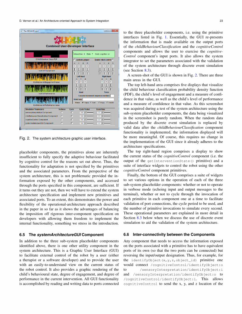
Fig. 2. The system architecture graphic user interface.
placeholder components, the primitives alone are inherentlyinsufficient to fully specify the adaptive behaviour facilitatedby cognitive control for the reasons set out above. Thus, thefunctionality for adaptation is not specified by the primitivesand the associated parameters. From the perspective of thesystem architecture, this is not problematic provided the in-formation exposed by the other components, and accessedthrough the ports specified in this component, are sufficient. Ifit turns out they are not, then we will have to extend the systemarchitecture specification and implement new primitives andassociated ports. To an extent, this demonstrates the power andflexibility of the operational-architecture approach describedin the paper in so far as it shows the advantages of balancingthe imposition off rigorous inter-component specification ondevelopers with allowing them freedom to implement theinternal functionality, something we stress in the introduction.
6.5 The systemArchitectureGUI Component
In addition to the three sub-system placeholder componentsidentified above, there is one other utility component in thesystem architecture. This is a Graphic User Interface (GUI)to facilitate external control of the robot by a user (eithera therapist or a software developer) and to provide the userwith an easily-to-understand view on the current status ofthe robot control. It also provides a graphic rendering of thechild’s behavioural state, degree of engagement, and degree ofperformance in the current intervention. All GUI functionalityis accomplished by reading and writing data to ports connected
to the three placeholder components, i.e. using the primitiveinterfaces listed in Fig. 1. Essentially, the GUI re-presentsthe information that is made available on the output portsof the childBehaviourClassification and the cognitiveControlcomponents and allows the user to exercise the cognitive-Control component’s input ports. It also allows the systemintegrator to set the parameters associated with the validationof the system architecture through discrete event simulation(see Section 8.3).
A screen-shot of the GUI is shown in Fig. 2. There are threemain areas in the GUI.
The top left-hand area comprises five displays that visualizethe child behaviour classification probability density function(PDF), the child’s level of engagement and a measure of confi-dence in that value, as well as the child’s level of performanceand a measure of confidence in that value. As this screenshotwas acquired during a test of the system architecture using thesub-system placeholder components, the data being visualizedin the screenshot is purely random. When the random dataproduced by the discrete event simulation is replaced byvalid data after the childBehaviourClassification componentfunctionality is implemented, the information displayed willbe more meaningful. Of course, this requires no change inthe implementation of the GUI since it already adheres to thearchitecture specifications.
The top right-hand region comprises a display to showthe current status of the cognitiveControl component (i.e. theoutput of the getInterventionState() primitive) and asuite of interface widgets to control the robot using the othercognitiveControl component primitives.
Finally, the bottom of the GUI comprises a suite of widgetsto set various options in the operation of each of the threesub-system placeholder components: whether or not to operatein verbose mode (echoing input and output messages to theterminal), whether or not to cycle through the invocation ofeach primitive in each component one at a time to facilitatevalidation of port connections, the cycle period to be used, andthe number of primitive invocations to simulate every second.These operational parameters are explained in more detail inSection 8.3 below when we discuss the use of discrete eventsimulation to aid the validation of the system architecture.
6.6 Inter-connectivity between the Components
Any component that needs to access the information exposedon the ports associated with a primitive has to have equivalentports of its own (so that the two ports can be connected) butreversing the input/output designation. Thus, for example, forthe identifyObject(x,y,z,object_id) primitive onewould connect /cognitiveControl/identifyObject:o
to /sensoryInterpretation/identifyObject:i
and /sensoryInterpretation/identifyObject:o to/cognitiveControl/identifyObject:i. This allowscognitiveControl to send the x, y, and z location of the

24 Journal of Software Engineering for Robotics 6(1), December 2015
object to be identified to sensoryInterpretation andthen to receive the identification number of that object fromsensoryInterpretation.
Regarding the connectivity between the four componentsin the DREAM system architecture, the following principlesapply.
Each sensoryInterpretation output port is connected to thecounterpart input port in the cognitiveControl and childBe-haviourClassification components.
Each sensoryInterpretation input port is connected to thecounterpart output port in the cognitiveControl component (butnot the childBehaviourClassification component).
Each childBehaviourClassification output port is connectedto the counterpart input port in the cognitiveControl compo-nent.
All of the cognitiveControl input and output ports will beconnected to the GUI component systemArchitectureGUI tofacilitate external control of the robot by a user (either atherapist or a software developer) and to provide the user withan easily-comprehended view on the current status of the robotcontrol. Furthermore, the child state, degree of engagement,and degree of performance output ports in the childBehaviour-Classification component will also be connected to the GUIand graphically rendered in a suitable manner.
7 SOFTWARE ENGINEERING STANDARDS ANDINTEGRATION PROCEDURE
As we noted in the introduction, an operational implementedarchitecture as a driver for sub-system development and in-tegration is insufficient by itself: you also need the userrequirements and system specification that define the softwarefunctionality as well as an effective software engineeringprocess. We addressed the user requirements in the previoussection and here we address briefly the software engineeringstandards that underpin the development process, focussingin particular on the quality assurance process in which theintegration procedure is embedded. Our strategy was to adopta set of software engineering standards for each phase of thesoftware development life-cycle — from component and sub-system specification, through component design, componentimplementation, and component and sub-system testing, todocumentation — but to keep these as minimal as possiblewhile at the same time not compromising software quality,placing special emphasis on the latter phases of the life-cycleto facilitate effective system integration.
We also adopted a set of procedures for quality assurance,focussing in particular on the procedures by which softwareis submitted for integration, tested, and checked against thesoftware engineering standards.
We distinguish between recommended standards that reflectdesirable practices and mandatory standards that reflect re-quired practices. DREAM component software developers androbot application developers are strongly encouraged to adhere
to the desirable practices but these standards do not form partof the criteria that will be used to decide whether or not a givencomponent of application can be included in the DREAMsoftware repository: that is, they do not form part of theDREAM software quality assurance process governing com-ponent integration. On the other hand, the required practicesdo form part of the software quality assurance process and acomponent or application will only be accepted for integrationin the release version if it complies with the correspondingmandatory standards.
In creating these standards, we have drawn from severalsources, including the GNU Coding Standards [37], JavaCode Conventions [38], C++ Coding Standard [39], and theDoxygen User Manual [40].
7.1 Component SpecificationOur operational-architecture approach aims to allow re-searchers and software developers as much freedom as pos-sible in the specification of the components that meet thefunctional requirements outlined above. Consequently, thisphase of the software development life-cycle are subject torecommended standards stipulating the required practices forrequirements eliciation, documentation of the underlying com-putational model, the functional specification (including a classand class-hierarchy definition), the data model (summarizedby an entity-relationship diagram, data dictionary, input func-tional, control, system configuration data, output functional,control, system configuration data for each process or threadin the component, and an object-relationship model whereappropriate), a process flow model (summarized using a data-flow diagram (DFD), identifying data flow, control flow, andpersistent data sources and sinks), and a behavioural model(summarized with a state transition diagram and an object-behaviour model, where appropriate).
7.2 Component DesignThe principles of good design have already been outlined theguidelines set out in Section 4. We consider these guidelines tobe a set of recommended standards for component design andwe will not repeat them here. However, it is important to notethat these guidelines give rise to several essential practices —and mandatory standards — in component implementation, asfollows.
7.3 Component ImplementationThe mandatory standards for implementation of componentsare the first set of standards that form part of the softwarequality assurance process and the component or applicationwill only be accepted for integration in the release version ifit complies with these standards.
The mandatory implementation standards address file namesand file organization, internal source code documentation,

D. Vernon et al./ An Architecture-oriented Approach to System Integration 25
and component functionality, targeting the 4Cs of configura-tion, coordination, computation, and communication. As notedabove, these mainly focus on the three Cs of configuration,coordination, and communication because these are the onesthat impact most on integration. Mandatory standards for thefourth C, computation, only relate to the manner in which thefunctionality is encapsulated using YARP (see Footnote 2).
The recommended implementation standards provide ex-tensive guidelines on programming style and programmingpractice, guidelines which would typically be mandatory inindustry but are very hard to enforce in collaborative researchprojects (see [41] for details).
All standards, mandatory and recommended, make referenceto an implementation of a prototype component which isavailable to all developers.
7.4 TestingDREAM software is subject to a spectrum of test procedures,including black-box unit tests, white-box structural tests, re-gression tests, and acceptance tests.
Black-box testing is a testing strategy that checks thebehaviour of a software unit — in this case a component —without being concerned with what is going on inside the unit’.Typically, it does this by providing a representative sample ofinput data (both valid and invalid), by describing the expectedresults, and then by running the component against this testdata to see whether or not the expected results are achieved.Component software developers must provide a unit test withevery component submitted for integration into the DREAMrelease and this unit test must be compliant with severalrequirements concerning application launch, data sources anddata sinks, filenames, file location, and test instructions. Theseinstructions should explain how the four Cs of communication,configuration, computation, and coordination are exercised bythe test.
White-box testing is a testing strategy that checks thebehaviour of a software unit or collection of units in a (sub-)system by exercising all the possible execution paths withinthat unit or system. Thus, white-box testing differes fundamen-tally from black-box testing in that it is explicitly concernedwith what is going on inside the unit. In DREAM we performwhite-box testing on a system-level only. Components are notsubject to white-box testing when being integrated into theDREAM software release, although developers themselves areencouraged to use white-box testing before submitting thecomponent for integration.
Regression testing refers to the practice of re-running allintegration tests — black-box and white-box — periodicallyto ensure that no unintentional changes have been introducedduring the ongoing development of the DREAM softwarerelease. These tests check for backward compatibility, ensuringthat what used to work in the past remains working.
DREAM software is also subject to periodic qualitativeassessment by psychotherapist practitioners to validate the
behaviour and performance of the system against their re-quirements. These tests take place whenever a new versionof the DREAM software release is made available to thepractitioners.
7.5 Quality Assurance Process and Integration Pro-cedureSoftware that is to be included in the release branch of theDREAM software repository must comply with the mandatorystandards outlines above. A strict procedure is followed tovalidate and test software developed by the partners prior tointegration into the release version. This takes the form ofa 57-point check-list organized under four headings derivedfrom the mandatory standards: Files and Directories, InternalSource Code Documentation, Component Functionality, andComponent Unit Testing (see [42] for details).
8 VALIDATION
We noted in the introduction that the contribution of the paperis primarily methodological, with secondary support for thatmethodology being provided by the discrete event simulationtechnique to facilitate handling the complexity of integrationthat naturally arises from a complete implementation of thefull system architecture and the large number of associatedinter-sub-system port communications. We note also that thisis a relatively straightforward approach that provides clearintegration acceptance criteria, i.e. hard constraints on thesoftware sub-system development outcome, without imposinghard constraints on all the other phases of the software devel-opment lifecycle, thereby substantially easing the burden onthe developers without compromising the integration process.
Thus, there are two aspects to be validated: (1) the im-pact this methodology has had on the developers’ softwareengineering practices, and (2) the impact it has had on theintegration process. These two issues are addressed in thefollowing sections, the first by reporting an impact analysison our team of developers and we address the second bydescribing our experience in integrating software that has beensubmitted by developers for integration. We also address athird element of validation concerning the authentication of theinter-component communications between the sub-systems inthe architecture. Since the number of communication ports canbe large, we propose in Section 8.3 the use of a discrete eventsimulation technique to facilitate handling the complexity thatnaturally arises from a complete implementation of the fullyoperational system architecture.
8.1 Assessment of Impact on Developers’ SoftwareEngineering PracticesThe success — or failure — of the operational-architecturecomponent-based software engineering approach to systemintegration being described and advocated in this paper hinges

26 Journal of Software Engineering for Robotics 6(1), December 2015
of three things: (a) the architecture needs to successfully en-capsulate the user requirements, (b) the information exchangesexposed by the architecture component sub-system interfacesmust be sufficient for the sub-system components to satisfythese requirements when integrated, and (c) the developershave to comply with the software engineering standards andquality assurance process on which successful integrationdepends. Furthermore, to be truly effective, the developersneed to believe that the time and effort to achieve complianceis worthwhile: that the process is effective and efficient, thatthe right balance of freedom and constraint has been struck,and that the operational system architecture facilitates theirwork. As we noted at the outset, system software integrationis a socio-technical problem, requiring both appropriate toolsand acceptance of the value of the associated methodologiesby the developers. In this section, we illustrate this acceptancein the DREAM developer team in two ways.
First, we report on a poll of developers’ views taken ap-proximately one year after the launch of the standards, qualityassurance process, and the operational system architecturecomponents and example application. This poll was taken todetermine what needs to be changed in the software stan-dards, integration procedure, system architecture, and supportdocumentation and software, and to gauge the impact of theoperational system architecture on their engineering practicesin the context of the DREAM project.
The poll took the form of a multiple choice questionnairewith a small number of questions (12) formulated in a mannerthat elicited feedback, positive or negative, as well as invitingcomments on what needed to be removed, changed, or addedfor each question topic. The initial version of the questionnairehad more questions but we reduced the number to increase thelikelihood of obtaining meaningful responses. Each questionoffered five choices: Strongly agree; Agree; Neither agree nordisagree (I don’t know / I don’t have an opinion); Disagree; andStrongly disagree. Questions were formulated both positivelyand negatively so that some questions required agreementto express a positive response with other questions requireddisagreement to express a positive response. In this way, weattempted to eliminate biased responses as a consequence ofthe manner in which the questions were framed. Furthermore,views on each issue (e.g. the usefulness of the system architec-ture) were elicited using more than one question; conclusionsare drawn only if the answers are consistent. The questionnairewas completed by each team of developers in the consortium.4
This resulted in four sets of responses. Clearly, the results donot have the statistical significance that would derive froma canvass of a much wider deployment of the approach wedescribe in the paper but they are indicative nonetheless ofthe perceived value of the approach by the team of developersinvolved in the DREAM research project.
4. The questionnaire and an anonymous version of the results are availableat www.dream2020.eu/software questionnaire.
The results of the poll were very positive: developers clearlyfelt that the balance of mandatory and recommended softwareengineering standards allows sufficient flexibility to designtheir own code and that the time and effort required to fa-miliarize themselves with the mandatory standards was worth-while. Significantly, they did not think there should be fewermandatory standards and they agreed that the support software,i.e. the protoype component and example applications, helpedillustrate the standards and assisted them in writing their owncomponents. Crucially, there was a very strong consensusthat the operational system architecture made it easier todesign software that can be integrated into the DREAM RETapplication and they prefer this approach to a more standardpaper-based description of the architecture. There was alsoagreement that the system architecture provided sufficientspecification of how their software should interface to othersubsystems. With one exception, they also felt that the workingarchitecture with operational port interfaces makes it easierto design software that can be integrated (the operationalport interfaces makes it harder in the sense of raising thethreshold on correctness before a component can be submittedfor integration). Developers were less impressed with theclarity of the integration procedure and this clearly needsto be streamlined. Of course it will only be possible toevaluate the long-term impact of the approach described inthis paper towards or after the end of the project. However,the initial phase of the development effort is critical andif the approach does indeed facilitate effective developmentpractices, manifested by efficient integration, then its impactwill be felt not only near the end of the project after muchtraining but also at the outset as it promotes the adoption ofeffective practices in the start-up phase. This is exactly whatwe have found so far in the project.
Second, it is noteworthy that the acceptance — and value— of the standards and the operational system architecture hasbeen manifested in an unexpected manner. One of the develop-ers produced, unforeseen and unsolicited, a YARP componentgenerator utility that produces the essentials of a componentwith all the required port interfaces in a manner that is fullycompliant with all the mandatory software standards for the4Cs and, therefore, with most of the integration procedure (itdoes not take care of the unit test applications). While this doesnot validate the efficacy of the operational system architecture,per se, it does validate the acceptance of the process on whichthe architecture is founded.
8.2 Assessment of Impact on the Integration Pro-cessWhile, as we noted above, it is still relatively early in theDREAM project, our experience with integration allows us todraw some important conclusions. First, the system architec-ture, viewed (as we said above) as a driver for both sub-systemdevelopment and integration, has been the cause of a prolon-gation of the development period. That is not to say that it has
D. Vernon et al./ An Architecture-oriented Approach to System Integration 27
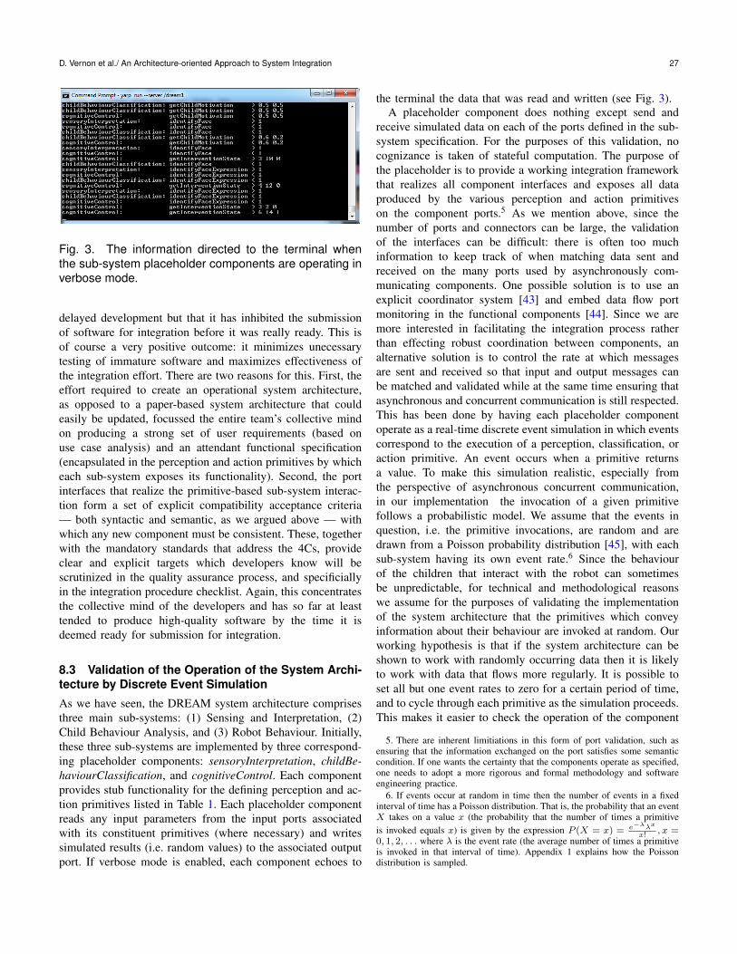
Fig. 3. The information directed to the terminal whenthe sub-system placeholder components are operating inverbose mode.
delayed development but that it has inhibited the submissionof software for integration before it was really ready. This isof course a very positive outcome: it minimizes unecessarytesting of immature software and maximizes effectiveness ofthe integration effort. There are two reasons for this. First, theeffort required to create an operational system architecture,as opposed to a paper-based system architecture that couldeasily be updated, focussed the entire team’s collective mindon producing a strong set of user requirements (based onuse case analysis) and an attendant functional specification(encapsulated in the perception and action primitives by whicheach sub-system exposes its functionality). Second, the portinterfaces that realize the primitive-based sub-system interac-tion form a set of explicit compatibility acceptance criteria— both syntactic and semantic, as we argued above — withwhich any new component must be consistent. These, togetherwith the mandatory standards that address the 4Cs, provideclear and explicit targets which developers know will bescrutinized in the quality assurance process, and specificiallyin the integration procedure checklist. Again, this concentratesthe collective mind of the developers and has so far at leasttended to produce high-quality software by the time it isdeemed ready for submission for integration.
8.3 Validation of the Operation of the System Archi-tecture by Discrete Event Simulation
As we have seen, the DREAM system architecture comprisesthree main sub-systems: (1) Sensing and Interpretation, (2)Child Behaviour Analysis, and (3) Robot Behaviour. Initially,these three sub-systems are implemented by three correspond-ing placeholder components: sensoryInterpretation, childBe-haviourClassification, and cognitiveControl. Each componentprovides stub functionality for the defining perception and ac-tion primitives listed in Table 1. Each placeholder componentreads any input parameters from the input ports associatedwith its constituent primitives (where necessary) and writessimulated results (i.e. random values) to the associated outputport. If verbose mode is enabled, each component echoes to
the terminal the data that was read and written (see Fig. 3).A placeholder component does nothing except send and
receive simulated data on each of the ports defined in the sub-system specification. For the purposes of this validation, nocognizance is taken of stateful computation. The purpose ofthe placeholder is to provide a working integration frameworkthat realizes all component interfaces and exposes all dataproduced by the various perception and action primitiveson the component ports.5 As we mention above, since thenumber of ports and connectors can be large, the validationof the interfaces can be difficult: there is often too muchinformation to keep track of when matching data sent andreceived on the many ports used by asynchronously com-municating components. One possible solution is to use anexplicit coordinator system [43] and embed data flow portmonitoring in the functional components [44]. Since we aremore interested in facilitating the integration process ratherthan effecting robust coordination between components, analternative solution is to control the rate at which messagesare sent and received so that input and output messages canbe matched and validated while at the same time ensuring thatasynchronous and concurrent communication is still respected.This has been done by having each placeholder componentoperate as a real-time discrete event simulation in which eventscorrespond to the execution of a perception, classification, oraction primitive. An event occurs when a primitive returnsa value. To make this simulation realistic, especially fromthe perspective of asynchronous concurrent communication,in our implementation the invocation of a given primitivefollows a probabilistic model. We assume that the events inquestion, i.e. the primitive invocations, are random and aredrawn from a Poisson probability distribution [45], with eachsub-system having its own event rate.6 Since the behaviourof the children that interact with the robot can sometimesbe unpredictable, for technical and methodological reasonswe assume for the purposes of validating the implementationof the system architecture that the primitives which conveyinformation about their behaviour are invoked at random. Ourworking hypothesis is that if the system architecture can beshown to work with randomly occurring data then it is likelyto work with data that flows more regularly. It is possible toset all but one event rates to zero for a certain period of time,and to cycle through each primitive as the simulation proceeds.This makes it easier to check the operation of the component
5. There are inherent limitiations in this form of port validation, such asensuring that the information exchanged on the port satisfies some semanticcondition. If one wants the certainty that the components operate as specified,one needs to adopt a more rigorous and formal methodology and softwareengineering practice.
6. If events occur at random in time then the number of events in a fixedinterval of time has a Poisson distribution. That is, the probability that an eventX takes on a value x (the probability that the number of times a primitiveis invoked equals x) is given by the expression P (X = x) = e−λλx
x!, x =
0, 1, 2, . . . where λ is the event rate (the average number of times a primitiveis invoked in that interval of time). Appendix 1 explains how the Poissondistribution is sampled.

28 Journal of Software Engineering for Robotics 6(1), December 2015
Listing 1. Pseudo-code algorithm for discrete event sim-ulation of placeholder componentwhi le ( i s S t o p p i n g ( ) != t r u e ) {
/ / p r o c e s s s i m u l a t i o n p a r a m e t e r s based on how much t i m e has p as sed
compute e l apsedT ime ( s i n c e p r e v i o u s i t e r a t i o n )compute cumula t i veT ime ( s i n c e c u r r e n t c y c l e s t a r t e d )
i f ( cumula t i veT ime > c y c l e P e r i o d ) {r e s e t cumula t i veT ime
i f ( c y c l e f l a g i s s e t ) { / / go t h r o u g h p r i m i t i v e s one a t a t i m es e t e v e n t r a t e f o r a l l p r i m i t i v e s t o zero , e x c e p t t h e t a r g e t p r i m i t i v eadvance t h e t a r g e t p r i m i t i v e f o r n e x t c y c l e
}e l s e { / / go t h r o u g h p r i m i t i v e s s i m u l t a n e o u s l y
s e t e v e n t r a t e f o r a l l p r i m i t i v e s t o t h e p a r a m e t e r v a l u e}
}
f o r a l l i n p u t p o r t s t h a t do n o t p r o v i d e i n p u t a rgumen t s f o r p r i m i t i v e sb e i n g s i m u l a t e d i n p l a c e h o l d e r component X {
r e a d i n p u t p o r t i n non−b l o c k i n g modei f v e r b o s e mode
w r i t e d a t a r e a d t o t e r m i n a l}
f o r a l l p r i m i t i v e s b e i n g s i m u l a t e d i n p l a c e h o l d e r component X {r e a d a s s o c i a t e d i n p u t p o r t i n non−b l o c k i n g mode ( i f i t e x i s t s )i f v e r b o s e mode
w r i t e d a t a r e a d t o t e r m i n a l
/∗ compute P o i s s o n d i s t r i b u t i o n mean and sample P o i s s o n d i s t r i b u t i o n ∗//∗ t o d e t e r m i n e number o f e v e n t s ( i . e . p r i m i t i v e i n v o c a t i o n s ) t o s i m u l a t e ∗/
lambda = e v e n t R a t e [ c u r r e n t p r i m i t i v e ++] ∗ e l apsedT ime ;c o u n t = s a m p l e P o i s s o n ( lambda ) ;
f o r ( i =0 ; i<c o u n t ; i ++) {g e n e r a t e random d a t aw r i t e d a t a t o t h e o u t p u t p o r t a s s o c i a t e d wi th t h i s p r i m i t i v ei f v e r b o s e mode
w r i t e d a t a r e a d t o t e r m i n a l}
}}
especially when all four placeholder components are workingtogether.
There are two phases in each iteration of the discrete eventloop. In the first phase, all input ports that do not provide inputarguments for primitives being simulated in the placeholdercomponent are read in non-blocking mode, again echoing dataread to the terminal when in verbose mode. In the secondphase, an invocation of each primitive in this placeholdercomponent is simulated by reading the input port associatedwith that primitive in non-blocking mode (if it exists). Ifin verbose mode, this data is echoed to the terminal. Then,the Poisson distribution is sampled to determine how manytimes that primitive has been called in the time elapsed sincethe previous iteration of the discrete event simulation loop(for details of the sampling process, see Appendix 1). Thisdetermines how many times the primitives output should bewritten to the associated output port. Random data is generatedfor each invocation and written to the associated output portand, if in verbose mode, the data is also echoed to the terminal.Listing 1 gives a pseudo-code algorithm for this simulationprocess. Note that the port named after the component andused for coordination (see Section 5) is not exercised inthis process since the command protocol is specified by thecomponent functionality and not by the system architectureand the use-case primitives. Once specified it can be included.
Four simulation parameters are provided to allow the de-
veloper to control the simulation without having to recompilethe placeholder code. These are:
verboseIf this parameter has the value on, messages will besent to the run server terminal to echo the input andoutput to/from each primitive; if off no messages aresent.
cycleIf this parameter has the value on, only one primitiveis set to have a non-zero event rate in each iteration ofthe discrete event simulation loop and therefore onlyone primitive will output data at the specified ratein any one iteration of the discrete event simulationloop. If the parameter has the value off all primitiveshave the specified non-zero event rate and all willoutput data at the rate determined by the probabilisticmodel.
cycle periodThis is the time period for which a primitive is theonly one to have a non-zero event rate.
event rateThis is the number of events (i.e. primitive invo-cations) per second. In the current implementation,the same event rate is applied to all primitives exceptin cycle mode. It would be more flexible to haveindividual rates for each primitive but we have notfound this to be necessary.
This event rate determines the Poisson distribution parameter,i.e. the mean number of events, computed as the event ratemultiplied by the time taken to execute one discrete eventloop. This event loop time is measured in real-time and is nota fixed discrete event simulation interval. Again, this producesa more realistic simulation to validate communication over theport connector.
This discrete event simulation provides a useful frameworkfor integration of new components. As we mentioned already,the functionality of each sub-system is being developed incre-mentally with new components being developed to implementeach primitive. Integration of these new primitives is madeeasier by simply setting the event rate of the stub versionsin this placeholder to zero, allowing the newly-integratedcomponent to read and write the requisite data to the relevantports instead of the placeholder sub-system component.
9 CONCLUSIONS
In this paper, we have argued that the adoption of CBSE in theguise of the CPC meta-model leads to a natural and effectivemethod of system architecture design and implementation thatfacilitates orderly integration but without imposing excessivelystrong engineering standards which might not be adopted byevery team of developers. This lightweight aspect is impor-tant as it is attractive for collaboratively-undertaken systemdevelopment where, unlike some more stringent industrial

D. Vernon et al./ An Architecture-oriented Approach to System Integration 29
development environments, developers voluntarily agree toadhere to the software engineering practices. In concert withthis, of course, is the need to support developers in adhering tothese guidelines. We have shown that the YARP middlewareis an effective way of doing this. While YARP was designedspecifically for the robotics domain, and provides many usefulrobotics and image processing tools, it is inherently general-purpose and makes for a very effective thin support environ-ment for any system that adopts the component-port-connectormeta-model, irrespective of its application domain.
One of the principle advantages of the CPC meta-modelis that it solves the problem of coarse-grained software reusein a straightforward manner if the practice of implementingcomponents so that they can be externally reconfigured isstrictly enforced. There are five aspects to this reconfiguration.First, there is the ability to provide a unique name for eachinstance of a component and propagation of that name tothe port names. Second, there is the ability to recast thecomponent interface by renaming any of the ports throughwhich the interfaces are exposed. Third, there is the ability toconfigure the component behaviour by reading all parametervalues either from a configuration file or the command lineinvocation. Fourth, there is the ability to automatically recon-figure the paths where the component searches for componentresources (e.g. configuration and data files) by modifying aspecific external configuration file rather than by recompilingthe component software. Fifth, there is the ability to alter theoperational behaviour of the component either at invocation-time by setting component parameters through commandline arguments or through configuration files, or at run-timethrough a standard component-specific port. Support for thedeveloper by the underlying robot programming environmentis crucial and YARP provides all the required mechanisms.
A second major advantage of this approach is that itprovides for the direct instantiation of a system architecture byrealizing sub-systems as placeholder components that providestubs for each constituent primitive and by exposing allassociated functionality through the component ports. Sub-system placeholder stub functionality is then incrementally re-placed with the final functional components. This operational-architecture approach to system development prioritizes therole of system integration by focussing explicitly on the meansby which components will be integrated, i.e. by instantiatingthe connectors between component ports, and — most impor-tantly — by providing a working implementation of these sub-system interfaces through the sub-system placeholder compo-nents. This reduces the complexity of the integration processsignificantly and provides developers with a clear template fortheir component port interfaces.
Finally, we have shown how the difficult task of validatingthe interaction between components in a realistic large-scalesystem architecture with 76 connectors can be eased signif-icantly by implementing the placeholder sub-system compo-nents as a discrete event simulation. This allows the system
integrator to adjust the rate at which the constituent stubprimitives are invoked and to control their invocation eitherby cycling through them, invoking them one at a time, ormore realistically by allowing all of them to be invoked inany one discrete event simulation time quantum accordingto a probabilistic model following a Poisson distribution. Bygiving the developer access to the four controls that govern thediscrete event simulation behaviour of each component (i.e.verbose mode echoing port data to the run-server terminal;rate of primitive invocation; cyclic invocation or concurrentinvocation; and cycle time) the operation of the completesystem can be validated more easily, as can the integrationof a functional component by overriding input/output of theassociated placeholder stub primitive, while still respecting theasynchronous and concurrent character of communication inCBSE.
Large-scale system development raises many problems, notleast of which is the difficulty in managing the develop-ment and integration processes. Our experience in developingthe DREAM system architecture has shown that the CBSEapproach described here — the use of the component-port-connector meta-model, adherence to the five practices associ-ated with designing components to facilitate external config-uration, the use of the YARP middleware platform to providefunctional support for these guidelines, and the use of discreteevent simulation to control the behaviour of stub primitive in-put/output — greatly eases the management of both processes.While CBSE is often used for facilitating reusability, we havedemonstrated here another benefit: substantially facilitatingthe development and integration process in collaborative, andoften geographically-distributed, research projects. It strikes agood balance between software engineering best practice andthe socio-technical problem of managing effective integrationof software developed by researchers that are not alwaysinclined to adopt extensive strict standards.
Before concluding, a final caveat is in order. In an idealworld, all developers would adhere to professional soft-ware engineering standards and state-of-the-art software en-gineering practices, especially with respect to formally- andsemantically-defined functional and non-functional require-ments and capabilities, e.g. model-driven engineering ap-proaches. We are not suggesting that the approach describedoffers an alternative to these more sophisticated approaches. Itis instead a compromise that adopts methodologically-soundpractices focussed on three of the four Cs in CBSE withminimal overhead in effort. If one requires greater assuranceof correctly specified and implemented software, then one haslittle choice but to make the necessary effort to adopt moresophisticated software engineering tools than those discussedin this article. Hopefully, all software, even software developedin collaborative research projects, will eventually be developedusing sophisticated tool chains. In the meantime, CBSE andthe operational-architecture approach described here provide auseful compromise.

30 Journal of Software Engineering for Robotics 6(1), December 2015
APPENDIX 1 SIMULATION OF RANDOM EVENTS
The system architecture described in this paper is initially im-plemented by three sub-system placeholder components, eachof which simulates the invocation of the suite of primitives thatconstitute that sub-system. To make this simulation realistic,the invocation of a given primitive follows a probabilisticmodel. We assume that the events in question, i.e. the primitiveinvocations, are random and are drawn from a Poisson proba-bility distribution. The goal, then, is to provide a function thatcan sample a Poisson distribution to determine the number ofinvocations that occur in a given period of time [45].
For discrete event simulation, we divide time up into dis-crete intervals of finite duration, e.g. 5 seconds and simulatethe behaviour of the system by computing what happensin each interval. For a simulation of primitive invocation,the question we need to answer is: ‘How many times wasthat primitive invoked in that finite interval?’ To answer thisquestion, we need to know the probability that primitive beinginvoked in any given interval. Actually, we need more: we needto know the probability that the primitive being invoked once,twice, three times, and so on.
If events occur at random in time then the number of eventsin a fixed interval of time has a Poisson distribution. Thatis, the probability that an event X takes on a value x (theprobability that number of cars arriving equals x) is given bythe expression
P (X = x) =e−λλx
x!x = 0, 1, 2, . . . (1)
where λ is the arrival rate (the average number of cars in thatinterval of time). So, for example, if the invocation rate is twocalls every second, then the probability of three invocations(in any five second interval) is given by
P (X = 3) =e−223
3!= 0.18 (2)
In more formal terms, Equation 1 is a probability massfunction of a discrete random variable X (i.e. X varies oroccurs randomly) and P (X = x) is the probability massfunction which defines the probability that X takes on thevalue x. The probability mass function is written
f(x) = P (X = x) (3)
The variable x is referred to as a random variable whereas Xis a random sample of a probability distribution.
The random variable is usually but not always (as we willsee later) a uniform random variable. This means that it takeson values in the interval [0 − 1] at random, with uniformprobability of each value occurring. This is typically what arandom number generator tries to achieve.
In general, this allows us to work out the probability that,e.g., a given primitive will be invoked n times in any oneinterval of time. However, this is not what we want. We requirethe number of times a primitive is actually invoked in any
specified interval of time, given that the invocation rate has aPoisson distribution with (known) mean λ.
To answer our question: how many times is the primitiveinvoked in a given time interval, we need to sample the(Poisson) probability distribution. That is, we need to find X ,given the value of x, a random variable, and given the Poissonparameter λ.
The normal way of sampling a probability distribution is tocompute the cumulative distribution function F (x):
F (x) = P (X ≤ x) = p =
∫ b
−∞f(x)dx (4)
and then solve for x, given a (usually uniform) random vari-able p (generated typically using a random number generator).This can be awkward to do since there is not always an explicitclosed form expression for F (x).7
In the case of the Poisson distribution, we will adopt theapproach given in [45] which computes the value of therandom sample X iteratively.
We have already noted that, if events occur at random intime, then the number of events in a fixed interval of timehas a Poisson distribution. We note now that for such randomevents, the time interval between events has an exponentialdistribution f(x), where
f(x) = λe−λx, λ > 0 (5)
This distribution has a cumulative distribution F (x), where
F (x) = p = 1− e−λx (6)
To find the inverse distribution, we solve for x:
x =−ln(1− p)
λ(7)
Thus, given a uniform random variable p (i.e. a random num-ber), we can compute the random sample from the exponentialdistribution straight-forwardly as x = −ln(1−p)
λ . Usually, weuse the expression
x =−ln(p)λ
(8)
since if 1− p is a uniform random variable then so too is p.The idea is to find how many exponential events (i.e. random
samples of the exponential distribution) just fit into a unit timeinterval. That number will have a Poisson distribution: its valuewill be the required (Poisson) random sample.
In detail, let ui be a uniform random variable and let vi bean exponential random variable. We find vi by sampling theexponential distribution. That is, vi is given by:
vi =− ln(uu)
λ(9)
To find how many exponential events X fit in one timeinterval, we try to find the value of X (which has a Poisson
7. Strictly speaking, this approach applies only for continuous probabilitydistributions.

D. Vernon et al./ An Architecture-oriented Approach to System Integration 31
distribution with parameter λ if we sample from an exponentialdistribution with parameter λ) such that
X−1∑i=0
vi < 1 ≤X∑i=0
vi, X = 0, 1, 2, . . . (10)
That is, the sum of the intervals between X−1 arrivals and Xarrivals bounds one time interval. Thus, the Poisson randomsample X we require is given by:
X∑i=1
−ln(ui)λ
< 1 ≤X+1∑i=1
−ln(ui)λ
,X = 0, 1, 2, . . . (11)
That is, X events just fit in one time interval. Multiplyingacross by −1/λ
X∑i=1
−ln(ui) > −λ ≥X+1∑i=1
ln(ui) (12)
The sum of logs equals the log of products, hence
ln
X−1∏i=0
ui > −λ ≥ ln
X∏i=0
ui (13)
Exponentiating:
X−1∏i=0
ui > e−λ ≥X∏i=0
ui (14)
This expression essentially says that for two successive valuesof X (e.g. X−1 and X , X = 0, 1, 2, . . .), u0u1u2 . . . uX−1 >e−λ and u0u1u2 . . . uX ≤ e−λ. This gives us the basis for aniterative procedure to compute X by taking progressively morerandom numbers (ui) and multiplying them together until wefind a product that is less that e−λ.
Specifically, we take a uniform random variable u0 (usinga random number generator). If u0 ≤ e−λ, we stop and takeX = 0. If u0 > e−λ, we generate another random number u1,form the product u0u1, and check again. If u0u1 ≤ e−λ, takeX = 1. We continue in this way until we find x such thatu0u1u2 . . . ux is the first product ≤ e−λ, and we then takeX = x. We state this in algorithmic form in Listing 2.
REFERENCES
[1] D. Brugali and E. Prassler, “Software engineering for robotics,” IEEERobotics and Automation Magazine, pp. 9, 15, March 2009. 1
[2] G. S. Broten, D. Makay, S. P. Monckton, and J. Collier, “The roboticsexperience — beyond components and middleware,” IEEE Robotics andAutomation Magazine, pp. 46–54, March 2009. 1
[3] D. Vanthienen, M. Klotzbucher, and H. Bruyninckx, “The 5C-basedarchitectural Composition Pattern: lessons learned from re-developingthe iTaSC framework for constraint-based robot programming,” Journalof Software Engineering for Robotics, vol. 5, no. 1, pp. 17–35, 2014. 1,4
[4] G. T. Heineman and W. T. Council, Component-Based Software Egineer-ing: Putting the pieces Together. Reading, Massachusetts: Addison-Wesley, 2001. 1
[5] C. Szyperski, Component Software: Beyond Object-Oriented Program-ming. Reading, Massachusetts: Addison-Wesley, 2002. 1
Listing 2. C function for sampling a Poisson distribution# i n c l u d e <s t d l i b . h># i n c l u d e <s t d i o . h># i n c l u d e <t ime . h># i n c l u d e <math . h>
/∗ Genera te a random sample from a P o i s s o n d i s t r i b u t i o n w i t h a g i v e n mean , lambda∗//∗ Use t h e f u n c t i o n rand ( ) t o g e n e r a t e a random number∗/
i n t s a m p l e P o i s s o n ( double lambda ) {
s t a t i c boo l f i r s t c a l l = t r u e ;i n t c o u n t ;double p r o d u c t ;double z e r o p r o b a b i l i t y ;
/∗ Seed t h e random−number g e n e r a t o r w i t h c u r r e n t t i m e so ∗//∗ t h a t t h e numbers w i l l be d i f f e r e n t e v e r y t i m e we run ∗/
i f ( f i r s t c a l l ) {s r a n d ( ( unsigned ) t ime ( NULL ) ) ;f i r s t c a l l = f a l s e ;
}
c o u n t = 0 ;p r o d u c t = ( double ) r and ( ) / ( double ) RAND MAX;
z e r o p r o b a b i l i t y = exp(−lambda ) ;
whi le ( p r o d u c t > z e r o p r o b a b i l i t y ) {c o u n t ++;p r o d u c t = p r o d u c t ∗ ( ( double ) r and ( ) / ( double ) RAND MAX) ;
}re turn ( c o u n t ) ;
}
[6] D. Brugali and P. Scandurra, “Component-Based Robotic Engineering(Part I),” IEEE Robotics and Automation Magazine, pp. 84–96, Decem-ber 2009. 1, 3
[7] D. Brugali and A. Shakhimardanov, “Component-Based Robotic Engi-neering (Part II),” IEEE Robotics and Automation Magazine, pp. 100–112, March 2010. 1, 3
[8] “http://www.omg.org.” 1, 4[9] G. Metta, P. Fitzpatrick, and L. Natale, “Yarp: yet another robot
platform,” International Journal on Advanced Robotics Systems, vol. 3,no. 1, pp. 43–48, 2006. 1, 5
[10] P. Fitzpatrick, E. Ceseracciu, D. E. Domenichelli, A. Paikan, G. Metta,and L. Natale, “A middle way for robotics middleware,” Journal ofSoftware Engineering for Robotics, vol. 5, no. 2, pp. 42–49, 2014. 1
[11] “http://www.dream2020.eu.” 2[12] A. Tapus, A. Peca, A. Aly, C. Pop, L. Jisa, S. Pintea, and D. O.
David, “Children with autism social engagement in interaction with nao,an imitative robot — a series of single case experiments,” InteractionStudies, vol. 13, no. 3, pp. 315–347, 2012. 2
[13] B. Vanderborght, R. Simut, J. Saldien, C. Pop, A. S. Rusu, S. Pineta, andD. O. David, “Using the social robot probo as a social story telling agentfor children with asd,” Interaction Studies, vol. 13, no. 3, pp. 348–372,2012. 2
[14] B. Scassellati, H. Admoni, and M. Mataric, “Robots for use in autismresearch,” Annual Review of Biomedical Engineering, vol. 14, pp. 275–294, 2012. 2
[15] H. Kozima, C. Nakagawa, and Y. Yasuda, “Interactive robots forcommunication-care: A case-study in autism therapy,” in Proc. IEEEInternational Workshop on Robot and Human Interactive Communica-tion (ROMAN), Nashville, TN, 2005. 2
[16] D. David, S. A. Matu, and O. A. David, “Robot-based psychotherapy:Concepts development, state of the art, and new directions,” Interna-tional Journal of Cognitive Therapy, vol. 7, no. 2, pp. 192–210, 2014.2
[17] S. Thill, C. Pop, T. Belpaeme, T. Ziemke, and B. Vanderborght,“Robot-assisted therapy for autism spectrum disorders with (partially)autonomous control: Challenges and outlook,” Paladyn, vol. 3, no. 4,pp. 209–217, 2012. 2
[18] M. Y. Jung, M. Balicki, A. Deguet, R. H. Taylor, and R. Kazanzides,“Lessons learned from development of component-based medical robotsystems,” Journal of Software Engineering for Robotics, vol. 5, no. 2,pp. 25–41, 2014. 3

32 Journal of Software Engineering for Robotics 6(1), December 2015
[19] D. Alonso, C. Vincente-Chicote, F. Ortiz, J. Pastor, and B. Alvarez,“V3CMM: a 3-view component meta-model for model-driven roboticsoftware development,” Journal of Software Engineering for Robotics,vol. 1, no. 1, pp. 3–17, 2010. 3
[20] C. A. R. Hoare, “Communicating sequential processes,” Communica-tions of the ACM, vol. 21, no. 8, pp. 666—677, 1978. 3
[21] H. Bruyninckx, M. Klotzbucher, N. Hochgeschwender, G. Kraetzschmar,L. Gherardi, and D. Brugali, “The BRICS component model: A model-based development paradigm for complex robotics software systems,” inProceedings of the 28th Annual ACM Symposium on Applied Computing,ser. SAC ‘13. New York, NY, USA: ACM, 2013, pp. 1758–1764. 1,3, 4
[22] H. Bruyninckx, “Robotics software framework harmonization by meansof component composability benchmarks,” BRICS Deliverable D8.1,2010, http://www.best-of-robotics.org. 3
[23] P. Soetens, H. Garcia, M. Klotzbucher, and H. Bruyninckx, “Firstestablished CAE tool integration,” BRICS Deliverable D4.1, 2010,http://www.best-of-robotics.org. 4
[24] A. Shakhimardanov, J. Paulus, N. Hochgeschwender, M. Reckhaus, andG. K. Kraetzschmar, “Best practice assessment of software technolo-gies for robotics,” BRICS Deliverable D2.1, 2010, http://www.best-of-robotics.org. 4
[25] M. Radestock and S. Eisenbach, “Coordination in evolving systems,” inTrends in Distributed Systems, CORBA and Beyond. Springer, 1996,pp. 162—176. 4
[26] C. Schlegel, A. Steck, and A. Lotz, “Model-driven software developmentin robotics: Communication patterns as key for a robotics componentmodel,” in Introduction to Modern Robotics. iConcept Press, 2011. 4,5
[27] M. Quigley, K. Conley, B. Gerkey, J. Faust, T. Foote, J. Leibs,R. Wheeler, and A. Ng, “Ros: an open-source robot operating system,”in ICRA Workshop on Open Source Software, 2009. 5
[28] J. Baillie, “Urbi: towards a universal robotic low-level programminglanguage,” in IEEE/RSJ International Conference on Intelligent Robotsand Systems, IROS 2005, 2005, pp. 3219—3224. 5
[29] P. Soetens, “A software framework for real-time and distributed robotand machine control,” Ph.D. dissertation, Department of MechanicalEngineering, Katholieke Universiteit Leuven, Belgium, 2006. 5
[30] A. Brooks, T. Kaupp, A. Makarenko, S. Williams, and A. Oreback,Software Engineering for Experimental Robotics, ser. Springer Tracts inAdvanced Robotics. Springer, 2007, ch. Orca: a component model andrepository, pp. 231—251. 5
[31] A. Makarenko, A. Brooks, and T. Kaupp, “On the benefits of makingrobotic software frameworks thin,” in IEEE/RSJ International Confer-ence on Intelligent Robots and Systems, IROS 2007, 2007. 5
[32] E. I. Barakova, J. C. C. Gillesen, B. E. B. M. Huskens, and T. Lourens,“End-user programming architecture facilitates the uptake of robots insocial therapies,” Robotics and Autonomous Systems, vol. 61, pp. 704–713, 2013. 5
[33] D. Vernon, G. Sandini, and G. Metta, “The iCub cognitive architec-ture: Interactive development in a humanoid robot,” in Proceedings ofIEEE International Conference on Development and Learning (ICDL),Imperial College, London, 2007. 6
[34] D. Vernon, C. von Hofsten, and L. Fadiga, A Roadmap for CognitiveDevelopment in Humanoid Robots, ser. Cognitive Systems Monographs(COSMOS). Berlin: Springer, 2010, vol. 11. 6
[35] D. Vernon, Artificial Cognitive Systems — A Primer. Cambridge, MA:MIT Press, 2014. 6
[36] C. Schlegel, “Communication patterns as key towards component-basedrobotics,” International Journal of Advanced Robotics Systems, vol. 3,no. 1, pp. 49–54, 2006. 6
[37] GNU coding standards. [Online]. Available: www.gnu.org/prep/standards/ 7
[38] Java code conventions. [Online]. Available: www.oracle.com/technetwork/java/codeconvtoc-136057.html 7
[39] C++ coding standards. [Online]. Available: http://www.possibility.com/Cpp/CppCodingStandard.html 7
[40] D. van Heesch. (2005) Doxygen user manual. [Online]. Available:www.doxygen.org 7
[41] D. Vernon, “Software engineering standards,” DREAM DeliverableD3.2, 2014, http://www.dream2020.eu. 7.3
[42] ——, “Quality assurance procedures,” DREAM Deliverable D3.3, 2014,http://www.dream2020.eu. 7.5
[43] M. Klotzbucher and H. Bruyninckx, “Coordinating robotics tasks andsystems with rFSM statecharts,” Journal of Software Engineering forRobotics, vol. 1, no. 3, pp. 28–56, 2012. 8.3
[44] A. Paikan, P. Fitzpatrick, G. Metta, and L. Natale, “Data flow port mon-itoring and arbitration,” Journal of Software Engineering for Robotics,vol. 5, no. 1, pp. 80–88, 2014. 8.3
[45] D. Cooke, A. H. Craven, and G. M. Clarke, Statistical Computing inPascal. London: Edward Arnold, 1984. 8.3, 9, 9
David Vernon is Professor of Informatics at theUniversity of Skovde, Sweden. His interests arecognitive robotics and computer vision, focus-ing on cognitive architectures, cognitive develop-ment, and models of autonomy. He is a SeniorMember of the IEEE, a Chartered Engineer ofthe Institution of Engineers of Ireland, and apast Fellow of Trinity College Dublin. He is theDREAM project’s research director and mainresponsible for system integration. Previously,he was the technical coordinator of the EU-
funded RobotCub project to develop the iCub humanoid robot. Prior toembarking on his university career, he was a software engineer withWestinghouse Electric.
Erik Billing is a a researcher in the InteractionLab, School of Informatics, University of Skovde,Sweden. His research involves robot learning,planning of goal directed actions, modeling var-ious aspects of human and animal cognition,and development of therapeutic tools for childrenwith autism spectrum disorder. He is also thehead of SweCog, the Swedish Cognitive Sci-ence Society.
Paul Hemeren is a Senior Lecturer in CognitiveScience and Head of Division in the School ofInformatics, University of Skovde, Sweden. Hereceived his Ph. D. from the University of Lundfor a thesis on human action representation andthe perception of biological motion. His mainresearch interests are in human and robot actionperception and understanding.
Serge Thill is an Associate Professor of Cogni-tive Science at the University of Skovde, Swedenand head of the Interaction Lab in the School ofInformatics. He received his Ph. D. from the Uni-versity of Leicester, UK. His main research inter-est is the modelling of the mechanisms underly-ing human embodied cognition and social inter-action with applications to cognitive robotics.
Tom Ziemke is Professor of Cognitive Scienceat the University of Skovde, Sweden and a Visit-ing Professor in Cognitive Systems in the Dept.of Computer and Information Science (IDA) atLinkoping University. He received his Ph. D. fromthe University of Sheffield, UK. His main re-search interest are embodied cognition and in-teraction, i.e. the role the body plays in cognitiveand emotional processes, in social interactions,and people’s interactions with different types oftechnology. He coordinates the DREAM project
as well as a Swedish research initiative called AIR on action andintention recognition in human interaction with autonomous systems.