AN ARCHAEOMETALLURGICAL STUDY OF EARLY … · figure 77 – sem images of pearlitic ghosting in bar...
191
1 AN ARCHAEOMETALLURGICAL STUDY OF EARLY MEDIEVAL IRON TECHNOLOGY An examination of the quality and use of iron alloys in iron artefacts from Early Medieval Britain Volume 2 Samantha Rebecca RUBINSON submitted for the degree of Doctor of Philosophy Division of Archaeological, Geographical and Environmental Sciences University of Bradford 2010
Transcript of AN ARCHAEOMETALLURGICAL STUDY OF EARLY … · figure 77 – sem images of pearlitic ghosting in bar...

1
AN ARCHAEOMETALLURGICAL STUDY OF EARLY MEDIEVAL
IRON TECHNOLOGY
An examination of the quality and use of iron alloys in iron
artefacts from Early Medieval Britain
Volume 2
Samantha Rebecca RUBINSON
submitted for the degree of
Doctor of Philosophy
Division of Archaeological, Geographical and Environmental Sciences
University of Bradford
2010

i
List of Figures and Tables
FIGURES .............................................................................................. 1
FIGURE 1 – MAP OF SITES ACROSS BRITAIN ............................................................................. 1
FIGURE 2 – MAP OF ROMAN BRITAIN (C. AD400) ................................................................... 2
FIGURE 3 – MAP OF EARLY ANGLO-SAXON BRITAIN (AD500) .................................................... 3
FIGURE 4 – MAP OF MIDDLE SAXON BRITAIN (AD700) ............................................................ 4
FIGURE 5 – LATE SAXON BRITAIN (AD900) ............................................................................ 5
FIGURE 6 – MAP OF THE WEALD ........................................................................................... 6
FIGURE 7 – MAP OF THE FOREST OF DEAN .............................................................................. 7
FIGURE 8 – IRON BLOOMERY FURNACES .................................................................................. 8
FIGURE 9 – FE-C PHASE DIAGRAM ......................................................................................... 8
FIGURE 10 – FE-P AND FE-AS PHASE DIAGRAMS ..................................................................... 9
FIGURE 11 – DUBÉ CLASSIFICATION SYSTEM .......................................................................... 10
FIGURE 12 – PATTERN WELDED BLADE ................................................................................. 10
FIGURE 13 – KNIFE MANUFACTURING TYPOLOGY .................................................................... 11
FIGURE 14 – VIKING SPOON AUGER FROM COPPERGATE .......................................................... 11
FIGURE 15 – DRESS FITTINGS .............................................................................................. 12
FIGURE 16 – EARLY MEDIEVAL LOCKS .................................................................................. 12
FIGURE 17 – VIKING KEY FROM COPPERGATE ........................................................................ 12
FIGURE 18 – EXAMPLES OF MATERIAL QUALITY ...................................................................... 13
FIGURE 19 – EXAMPLES OF ARTEFACT CLASSES ....................................................................... 14
FIGURE 20 – EXAMPLES OF SECTION PLACEMENTS .................................................................. 15
FIGURE 21 – SEM VS. EMPA ANALYSES .............................................................................. 16
ii
FIGURE 22 – GRAIN BOUNDARY GHOSTING ........................................................................... 16
FIGURE 23 – INTER-GRANULAR GHOSTING ............................................................................ 17
FIGURE 24 – EDGE EFFECT GHOSTING ................................................................................... 17
FIGURE 25 – SLAG INCLUSION GHOSTING IN WP115 .............................................................. 18
FIGURE 26 – PEARLITIC GHOSTING IN SOU99-92 ................................................................. 18
FIGURE 27 – MAP OF THE LOCATION BRENT KNOLL ................................................................ 19
FIGURE 28 – CROSS-SECTION OF NAIL BN310 ....................................................................... 20
FIGURE 29 – CROSS-SECTION OF NAIL BN334 ....................................................................... 21
FIGURE 30 – MAP OF THE LOCATION OF CANTERBURY ............................................................. 22
FIGURE 31 – THE CROSS-SECTION OF BAR CC299 .................................................................. 23
FIGURE 32 – MAP OF THE LOCATION OF SOUTHAMPTON ......................................................... 24
FIGURE 33 – GHOSTING STRUCTURES IN SOUTHAMPTON ......................................................... 25
FIGURE 34 – THE CROSS-SECTION OF KNIFE SOU98-38 .......................................................... 25
FIGURE 35 –MAP OF THE LOCATION OF THETFORD AND THE BRANDON ROAD EXCAVATION ............ 26
FIGURE 36 – GHOSTING STRUCTURES OF THETFORD ............................................................... 27
FIGURE 37 – MAP OF THE LOCATION OF WHARRAM PERCY ...................................................... 28
FIGURE 38 – GHOSTING STRUCTURES AT WHARRAM PERCY ..................................................... 29
FIGURE 39 – THE CROSS-SECTION OF NAIL HEAD WP218 ........................................................ 30
FIGURE 40 – MAP OF THE LOCATION OF WINCHESTER ............................................................. 31
FIGURE 41 – MAP OF THE LOCATION OF WORCESTER .............................................................. 32
FIGURE 42 – MAP OF THE LOCATION OF YORK AND OF THE LAYOUT OF JORVIK ............................. 33
FIGURE 43 – GHOSTING STRUCTURES IN YORK ....................................................................... 34
FIGURE 44 – THE CROSS-SECTION OF SPOON AUGER YO9439................................................... 34
FIGURE 45 – MCDONNELL’S (1992) RESULTS IN TERMS OF THE CLASSES .................................... 35

iii
FIGURE 46 – COMPARING MCDONNELL’S RESULTS TO THE CURRENT STUDY FOR THE CLASS 1 AND
CLASS 3 ARTEFACTS .......................................................................................................... 36
FIGURE 47 – TIMELINE OF SITES .......................................................................................... 37
FIGURE 48 – ALLOY USAGE IN SINGLE ALLOY ARTEFACTS ........................................................... 37
FIGURE 49 – SINGLE ALLOY CONSTRUCTION MATERIAL QUALITY ............................................... 38
FIGURE 50 – USE OF HETEROGENEOUS IRON IN ARTEFACT CONSTRUCTION ................................... 38
FIGURE 51 – THE USE OF HETEROGENEOUS IRON IN CLASS 1 ARTEFACT CONSTRUCTION ................. 39
FIGURE 52 – THE USE OF HETEROGENEOUS IRON IN CLASS 2 ARTEFACT CONSTRUCTION ....... 39
FIGURE 53 – PILED COMPOSITE ARTEFACT MANUFACTURE TYPES ............................................... 40
FIGURE 54 – CLASS DISTRIBUTION OF CLEAN ARTEFACTS .......................................................... 40
FIGURE 55 – EDGED TOOL COMPOSITE CONSTRUCTION ARTEFACTS ............................................ 41
FIGURE 56 –TYPE 2 EDGED TOOL KNIFE BACK CONSTRUCTION ................................................... 41
FIGURE 57 – ALLOY USAGE IN CLASS 1 EDGED TOOLS WITH COMPOSITE CONSTRUCTION ................. 42
FIGURE 58 –MATERIAL QUALITY OF ALLOYS USED IN COMPOSITE CONSTRUCTION ARTEFACTS .......... 42
FIGURE 59 – AVERAGE FERRITE GRAIN SIZE PER ARTEFACT ........................................................ 43
FIGURE 60 – FORMS OF FERRITIC IRON USED BY EARLY SMITHS .................................................. 43
FIGURE 61 - COMPOSITE ARTEFACTS WHERE FERRITE WAS USED AS AN INDIVIDUAL ALLOY COMPONENT
..................................................................................................................................... 44
FIGURE 62 – PERCENT OF ARTEFACTS BASED ON CLASS WITH FERRITE BOTH AS INDIVIDUAL ALLOY USE
AND IN HETEROGENEOUS IRON ............................................................................................ 44
FIGURE 63 –CLEANNESS OF FERRITIC IRON USED AS INDIVIDUAL COMPONENTS AND IN HETEROGENEOUS
IRON .............................................................................................................................. 45
FIGURE 64 –NUMBER OF ARTEFACTS CONTAINING EACH FORM OF HIGH CARBON STEEL .................. 45
FIGURE 65 –HIGH CARBON STEEL USAGE BASED ON CLASS AND FORM ......................................... 46

iv
FIGURE 66 – THE LOW CARBON STEEL USAGE IN THE EARLY MEDIEVAL ARTEFACTS ......................... 46
FIGURE 67 –LOW CARBON STEEL USAGE BASED ON CLASS AND TYPE OF MANUFACTURE .................. 47
FIGURE 68 – CROSS-SECTIONS OF NAIL WP556 .................................................................... 48
FIGURE 69 – CARBON VERSUS PHOSPHORUS IN STEELS ............................................................ 49
FIGURE 70 – CROSS SECTION FROM KNIFE CC397 .................................................................. 50
FIGURE 71 – CARBURIZATION OF LOW PHOSPHORUS AREA ....................................................... 51
FIGURE 72 – THE AVERAGE PHOSPHORUS CONTENT FROM ALL 167 GHOSTED FERRITIC/PHOSPHORIC
IRON TEST SITES ................................................................................................................ 51
FIGURE 73 – GHOSTING AND PHOSPHORUS CONTENT IN NAIL WP556 ....................................... 52
FIGURE 74 – COMMON DUBÉ FORMS INCLUDING ALLOTRIOMORPHS .......................................... 53
FIGURE 75 – SEM SECONDARY ELECTRON IMAGE OF GRAIN BOUNDARY GHOSTING STRUCTURES WITH
SEM/EDS PHOSPHORUS MEASUREMENTS ............................................................................ 53
FIGURE 76 – INTER-GRANULAR GHOSTING AS AN EDGE EFFECT IN SOU31-669 ........................... 54
FIGURE 77 – SEM IMAGES OF PEARLITIC GHOSTING IN BAR SOU31-814 ................................... 54
FIGURE 78 – SEM IMAGES OF PEARLITIC GHOSTING IN KNIFE SOU24-22 ................................... 55
FIGURE 79 – SLAG INCLUSION GHOSTING IN BAR SOU31-814 ................................................. 56
FIGURE 80 – SEM SECONDARY ELECTRON IMAGE OF A GHOSTED SLAG INCLUSION IN BAR SOU31-814
..................................................................................................................................... 57
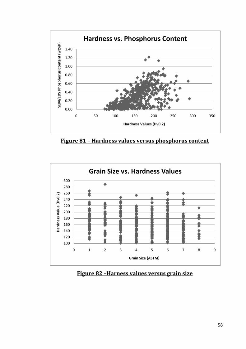
FIGURE 81 – HARDNESS VALUES VERSUS PHOSPHORUS CONTENT ............................................... 58
FIGURE 82 –HARNESS VALUES VERSUS GRAIN SIZE .................................................................. 58
FIGURE 83 – HARDNESS VALUES OF GHOSTED PHOSPHORIC IRON VERSUS HARDNESS VALUES OF UN-
GHOSTED PHOSPHORIC IRON ............................................................................................... 59
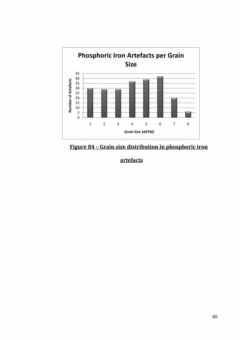
FIGURE 84 – GRAIN SIZE DISTRIBUTION IN PHOSPHORIC IRON ARTEFACTS .................................... 60
FIGURE 85 – GRAIN SIZE DISTRIBUTION OF FERRITIC IRON ARTEFACTS ......................................... 61

v
FIGURE 86 – GRAIN SIZE VERSUS ELEMENTAL COMPOSITION ..................................................... 61
FIGURE 87 – PHOSPHORIC IRON USAGE BASED ON CLASS AND CONSTRUCTION .............................. 62
FIGURE 88 – SINGLE ALLOY ARTEFACTS DIVIDED BASED ON CLASS ............................................... 62
FIGURE 89 – INDIVIDUAL ALLOY COMPONENTS OF COMPOSITE ARTEFACTS DIVIDED BASED ON CLASS . 63
FIGURE 90 – MANUFACTURE TYPES OF HEAT-TREATED ARTEFACTS ............................................. 64
FIGURE 91 – CONSTRUCTION TECHNIQUES IN CLASS 1 AND CLASS 2 ARTEFACTS ........................... 64
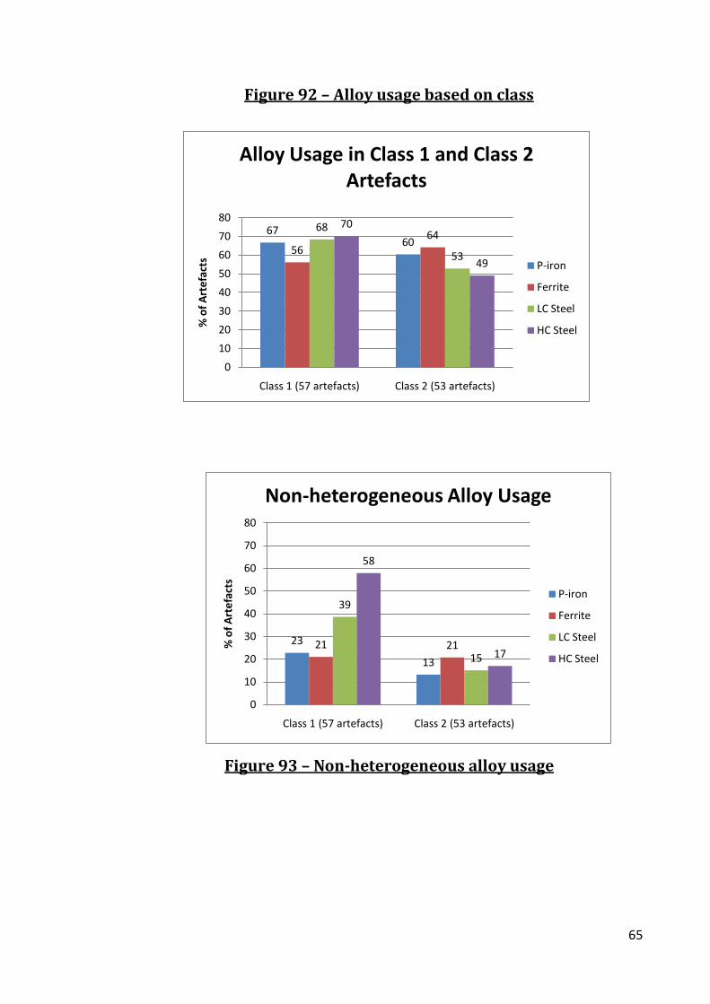
FIGURE 92 – ALLOY USAGE BASED ON CLASS .......................................................................... 65
FIGURE 93 – NON-HETEROGENEOUS ALLOY USAGE ................................................................. 65
FIGURE 94 – MANUFACTURE OF THE CLASS 3 ARTEFACTS ........................................................ 66
FIGURE 95 – OVERALL ALLOY USAGE FOR CLASS 3 ARTEFACTS ................................................... 66
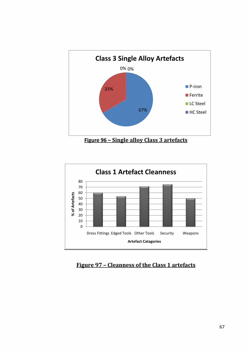
FIGURE 96 – SINGLE ALLOY CLASS 3 ARTEFACTS ..................................................................... 67
FIGURE 97 – CLEANNESS OF THE CLASS 1 ARTEFACTS .............................................................. 67
FIGURE 98 – COMPARING THE CLEANNESS OF THE THREE CLASSES .............................................. 68
FIGURE 99 – ARTEFACT MANUFACTURING TYPOLOGY BASED ON CROSS-SECTIONS ......................... 69
FIGURE 100 - MAP OF SITES ............................................................................................... 70
FIGURE 101 – ARTEFACT CONSTRUCTION FROM ALL SITES ........................................................ 70
FIGURE 102 – MANUFACTURE BY SITE ................................................................................. 71
FIGURE 103 – COMPARING CLASS 1 AND CLASS 2 MANUFACTURE ............................................. 72
FIGURE 104 – A COMPARISON OF OVERALL ALLOY USAGE IN THE ARCHAEOLOGICAL SITES ............... 73
FIGURE 105 – A COMPARISON OF NON-HETEROGENEOUS ALLOY USAGE IN THE ARCHAEOLOGICAL SITE
..................................................................................................................................... 74
FIGURE 106 – CLEANNESS OF IRON BY SITE............................................................................ 75

vi
TABLES ............................................................................................. 76
TABLE 1 – HARDNESS VALUES FOR PHASES OF CARBON-IRON ALLOYS .......................................... 76
TABLE 2 – HEAT-TREATMENT AT EARLY MEDIEVAL SETTLEMENT SITES ........................................ 76
TABLE 3 – MAJOR ARTEFACT TYPES ...................................................................................... 77
TABLE 4 – OTHER ARTEFACT TYPES ...................................................................................... 77
TABLE 5 – SITE CODES ....................................................................................................... 77
TABLE 6 – RESULTS OF SEM AND EMPA ANALYSES ................................................................ 78
TABLE 7 – SUMMARY OF BRENT KNOLL ARTEFACTS ................................................................. 78
TABLE 8 – CLASS 1 ALLOY SUMMARY FOR BRENT KNOLL .......................................................... 79
TABLE 9 – BRENT KNOLL CLASS 1 ARTEFACT ANALYSES ............................................................ 80
TABLE 10 – BRENT KNOLL CLASS 2 AND CLASS 3 ARTEFACT ANALYSES ........................................ 81
TABLE 11 – CLASS 2 ALLOY USAGE FOR BRENT KNOLL ............................................................. 82
TABLE 12 – CLASS 3 ALLOY USAGE FOR BRENT KNOLL ............................................................. 82
TABLE 13 – PHOSPHORUS IN STEEL IN THE BRENT KNOLL ASSEMBLAGE ....................................... 82
TABLE 14 – DATA ON THE PHOSPHORIC IRON IN THE BRENT KNOLL ASSEMBLAGE .......................... 83
TABLE 15 – ANALYSIS OF NAIL BN310 ................................................................................. 84
TABLE 16 – ANALYSIS OF NAIL BN334 ................................................................................. 84
TABLE 17 – MANUFACTURE SUMMARY FOR THE BRENT KNOLL ARTEFACTS .................................. 85
TABLE 18 – ALLOY USAGE SUMMARY FOR CLASS COMPARISON IN THE BRENT KNOLL ASSEMBLAGE ... 85
TABLE 19 – ALLOY USAGE SUMMARY FOR THE BRENT KNOLL ASSEMBLAGE .................................. 85
TABLE 20 – CLEANNESS OF THE BRENT KNOLL ASSEMBLAGE ..................................................... 85
TABLE 21 – SUMMARY DESCRIPTION OF THE IRON ARTEFACTS FROM CANTERBURY ........................ 86
TABLE 22 – CANTERBURY CLASS 1 ARTEFACT ANALYSES ........................................................... 87

vii
TABLE 23 – CANTERBURY CLASS 2 ARTEFACT ANALYSIS ............................................................ 88
TABLE 24 – CLASS 1 ALLOY USAGE SUMMARY FOR THE CANTERBURY ASSEMBLAGE ........................ 89
TABLE 25 – CLASS 2 ALLOY USAGE SUMMARY FOR THE CANTERBURY ASSEMBLAGE ........................ 89
TABLE 26 – CLASS 3 ALLOY USAGE SUMMARY FOR THE CANTERBURY ASSEMBLAGE ........................ 89
TABLE 27 – CANTERBURY CLASS 2 ARTEFACT ANALYSIS ............................................................ 90
TABLE 28 – PHOSPHORIC IRON ANALYSES FOR THE CLASS 1 ARTEFACTS FROM THE CANTERBURY
ASSEMBLAGE ................................................................................................................... 91
TABLE 29 – PHOSPHORUS IN STEEL IN THE CANTERBURY ASSEMBLAGE ........................................ 94
TABLE 30 – ANALYSIS OF BAR CC299 .................................................................................. 95
TABLE 31 – MANUFACTURE SUMMARY FOR THE CANTERBURY ARTEFACTS ................................... 95
TABLE 32 – ALLOY USAGE SUMMARY FOR CLASS COMPARISON FOR THE CANTERBURY ASSEMBLAGE.. 95
TABLE 33 – ALLOY USAGE SUMMARY OF THE CANTERBURY ARTEFACTS ....................................... 96
TABLE 34 – CLEANNESS OF THE ARTEFACTS FROM CANTERBURY BY CLASS .................................... 96
TABLE 35 – SUMMARY OF THE IRON ARTEFACTS FROM SAXON SOUTHAMPTON ............................ 97
TABLE 36 – SOUTHAMPTON CLASS 1 ARTEFACT ANALYSIS ........................................................ 98
TABLE 37 – SOUTHAMPTON CLASS 2 AND CLASS 3 ARTEFACT ANALYSES ................................... 100
TABLE 38 – CLASS 1 ALLOY USAGE SUMMARY FOR THE SOUTHAMPTON ASSEMBLAGE .................. 101
TABLE 39 – CLASS 2 ALLOY USAGE SUMMARY FOR THE SOUTHAMPTON ASSEMBLAGE .................. 101
TABLE 40 – CLASS 3 ALLOY USAGE SUMMARY FOR THE SOUTHAMPTON ASSEMBLAGE .................. 101
TABLE 41 – PHOSPHORIC IRON IN SOUTHAMPTON ................................................................ 102
TABLE 42 – SUMMARY OF INDICATORS IN THE SOUTHAMPTON ASSEMBLAGE ............................. 105
TABLE 43 – ANALYSIS OF KNIFE SOU98-38 ........................................................................ 105
TABLE 44 – RESULTS FROM MCDONNELL’S (1987B , 1987A) ANALYSIS OF SOUTHAMPTON
ARTEFACTS .................................................................................................................... 105

viii
TABLE 45 – PHOSPHORUS IN STEEL IN THE SOUTHAMPTON ASSEMBLAGE .................................. 106
TABLE 46 – MANUFACTURE SUMMARY FOR THE SOUTHAMPTON ARTEFACTS ............................. 108
TABLE 47 – AVERAGE HARDNESS FOR FERRITE IN SOUTHAMPTON CLASSES ................................. 108
TABLE 48 – ALLOY USAGE SUMMARY FOR CLASS COMPARISON FOR SOUTHAMPTON .................... 108
TABLE 49 – ALLOY USAGE SUMMARY OF THE SOUTHAMPTON ARTEFACTS .................................. 109
TABLE 50 – CLEANNESS OF THE ARTEFACTS FROM SOUTHAMPTON BY CLASS .............................. 109
TABLE 51 – SUMMARY DESCRIPTION OF THE IRON ARTEFACTS FROM THETFORD ......................... 110
TABLE 52 – CLASS 1 ALLOY USAGE SUMMARY OF THE THETFORD ASSEMBLAGE ........................... 111
TABLE 53 – CLASS 1 ARTEFACT ANALYSIS FROM THE THETFORD ASSEMBLAGE ............................. 112
TABLE 54 – CLASS 2 ARTEFACT ANALYSIS FROM THE THETFORD ASSEMBLAGE ............................. 113
TABLE 55 – CLASS 2 ALLOY USAGE SUMMARY OF THE THETFORD ASSEMBLAGE ........................... 115
TABLE 56 – CLASS 3 ALLOY USAGE SUMMARY OF THE THETFORD ASSEMBLAGE ........................... 115
TABLE 57 – UI ALLOY USAGE SUMMARY OF THE THETFORD ASSEMBLAGE .................................. 115
TABLE 58 – CLASS 3 AND UI ARTEFACT ANALYSIS FOR THE THETFORD ASSEMBLAGE ..................... 116
TABLE 59 – PHOSPHORIC ANALYSES IRON FOR THE THETFORD ASSEMBLAGE ............................... 117
TABLE 60 – PHOSPHORUS IN STEEL AT THETFORD ................................................................. 120
TABLE 61 – PHOSPHORIC IRON INDICATORS IN THE THETFORD ASSEMBLAGE .............................. 121
TABLE 62 – MANUFACTURE SUMMARY FOR THE THETFORD ARTEFACTS .................................... 121
TABLE 63 – AVERAGE HARDNESS FOR FERRITE IN THE THETFORD CLASSES .................................. 121
TABLE 64 – THETFORD ALLOY USAGE BASED ON CLASS ........................................................... 121
TABLE 65 – ALLOY USAGE SUMMARY FOR THE THETFORD ASSEMBLAGE .................................... 122
TABLE 66 – CLEANNESS OF THE ARTEFACTS FROM THETFORD BY CLASS ..................................... 122
TABLE 67 – SUMMARY OF THE IRON ARTEFACTS FROM WHARRAM PERCY ................................. 123
TABLE 68 – CLASS 1 ARTEFACT ANALYSIS FOR WHARRAM PERCY ............................................. 125

ix
TABLE 69 – CLASS 2 ARTEFACT ANALYSIS FOR WHARRAM PERCY ............................................. 126
TABLE 70 – CLASS 3 ARTEFACT ANALYSIS FOR WHARRAM PERCY ............................................. 127
TABLE 71 – CLASS 1 ALLOY USAGE FOR THE WHARRAM PERCY ASSEMBLAGE.............................. 128
TABLE 72 – CLASS 2 ALLOY USAGE FOR THE WHARRAM PERCY ASSEMBLAGE.............................. 128
TABLE 73 – CLASS 3 ALLOY USAGE FOR THE WHARRAM PERCY ASSEMBLAGE.............................. 128
TABLE 74 – PHOSPHORIC IRON ANALYSES FROM THE WHARRAM PERCY ASSEMBLAGE .................. 129
TABLE 75 – PHOSPHORUS IN STEEL IN THE WHARRAM PERCY ASSEMBLAGE ............................... 132
TABLE 76 – PHOSPHORIC IRON INDICATORS IN THE WHARRAM PERCY ASSEMBLAGE .................... 133
TABLE 77 – ANALYSIS OF NAIL WP218 ............................................................................ 133
TABLE 78 – MANUFACTURE SUMMARY FOR THE WHARRAM PERCY ARTEFACTS .......................... 133
TABLE 79 – AVERAGE HARDNESS FOR FERRITE IN THE WHARRAM PERCY CLASSES........................ 134
TABLE 80 – WHARRAM PERCY ALLOY USAGE BASED ON CLASS................................................. 134
TABLE 81 –ALLOY USAGE SUMMARY FOR THE WHARRAM PERCY ASSEMBLAGE ........................... 134
TABLE 82 – CLEANNESS OF THE ARTEFACTS FROM WHARRAM PERCY BY CLASS ........................... 135
TABLE 83 – SUMMARY OF THE IRON ARTEFACTS FROM WINCHESTER ........................................ 135
TABLE 84 – MANUFACTURE SUMMARY FOR THE WINCHESTER ARTEFACTS ................................. 135
TABLE 85 – CLASS 1 ALLOY USAGE FOR THE WINCHESTER ASSEMBLAGE .................................... 135
TABLE 86 – PHOSPHORIC IRON IN THE WINCHESTER ASSEMBLAGE ........................................... 136
TABLE 87 –CLASS 1 ARTEFACT ANALYSIS FOR THE WINCHESTER ASSEMBLAGE ............................. 137
TABLE 88 – PHOSPHORUS IN THE STEEL FROM THE WINCHESTER ASSEMBLAGE ........................... 138
TABLE 89 – SUMMARY OF THE IRON ARTEFACTS FROM WORCESTER ......................................... 139
TABLE 90 – CLASS 1 ARTEFACT ANALYSIS FOR THE WORCESTER ASSEMBLAGE ............................. 140
TABLE 91 – CLASS 2 AND CLASS 3 ARTEFACTS ANALYSIS FOR THE WORCESTER ASSEMBLAGE ......... 141
TABLE 92 – CLASS 1 ALLOY USAGE IN THE WORCESTER ASSEMBLAGE ....................................... 142

x
TABLE 93 – CLASS 2 ALLOY USAGE IN THE WORCESTER ASSEMBLAGE ....................................... 142
TABLE 94 – CLASS 3 ALLOY USAGE IN THE WORCESTER ASSEMBLAGE ....................................... 142
TABLE 95 – PHOSPHORIC IRON ANALYSES FROM WORCESTER ............................................ 143
TABLE 96 – MANUFACTURE OF THE WORCESTER ARTEFACTS .............................................. 144
TABLE 97 – AVERAGE HARDNESS FOR FERRITE IN THE WHARRAM PERCY CLASSES........................ 144
TABLE 98 – WORCESTER ALLOY USAGE BASED ON CLASS ........................................................ 144
TABLE 99 – ALLOY USAGE SUMMARY FOR THE WORCESTER ASSEMBLAGE .................................. 144
TABLE 100 – CLEANNESS OF THE ARTEFACTS FROM WORCESTER BY CLASS ................................. 145
TABLE 101 – SUMMARY OF THE IRON SMELTING AND SMITHING EVIDENCE FROM COPPERGATE, YORK,
EXCAVATION .................................................................................................................. 145
TABLE 102 – SUMMARY OF THE IRON ARTEFACTS FROM YORK ................................................ 145
TABLE 103 –CLASS 1 ARTEFACTS ANALYSIS FOR THE YORK ASSEMBLAGE.................................... 147
TABLE 104 – CLASS 2 ARTEFACTS ANALYSIS FOR THE YORK ASSEMBLAGE ................................... 149
TABLE 105 – CLASS 3 ARTEFACTS ANALYSIS FOR THE YORK ASSEMBLAGE ................................... 150
TABLE 106 – CLASS 1 ALLOY USAGE IN THE YORK ASSEMBLAGE .............................................. 151
TABLE 107 – CLASS 2 ALLOY USAGE IN THE YORK ASSEMBLAGE .............................................. 151
TABLE 108 – CLASS 3 ALLOY USAGE IN THE YORK ASSEMBLAGE .............................................. 151
TABLE 109 – PHOSPHORIC IRON IN YORK............................................................................ 152
TABLE 110 – PHOSPHORUS IN THE STEEL OF THE YORK ASSEMBLAGE ........................................ 155
TABLE 111 – PHOSPHORIC IRON INDICATORS IN THE YORK ASSEMBLAGE ................................... 156
TABLE 112 – ANALYSIS OF SPOON AUGER YO9439 .............................................................. 156
TABLE 113 – ARTEFACTS EXAMINED BY MCDONNELL’S (1992) ANALYSIS OF ARTEFACTS FROM YORK
................................................................................................................................... 156
TABLE 114 – RESULTS FROM MCDONNELL’S (1992) ANALYSIS OF ARTEFACTS FROM YORK .......... 157

xi
TABLE 115 – MANUFACTURE SUMMARY FOR THE YORK ARTEFACTS ......................................... 157
TABLE 116 – AVERAGE HARDNESS FOR FERRITE IN THE YORK CLASSES ....................................... 157
TABLE 117 – YORK ALLOY USAGE BASED ON CLASS ................................................................ 157
TABLE 118 – ALLOY USAGE SUMMARY FOR THE YORK ASSEMBLAGE ......................................... 158
TABLE 119 – CLEANNESS OF THE ARTEFACTS FROM YORK BY CLASS .......................................... 158
TABLE 120 – SITE BACKGROUND SUMMARY ........................................................................ 159
TABLE 121 – SUMMARY OF ARTEFACT TYPES FROM ALL EIGHT SITES ......................................... 160
TABLE 122 – SUMMARY OF ARTEFACTS IN EACH CLASS PER SITE ............................................... 161
TABLE 123 – SINGLE ALLOY CONSTRUCTION SUMMARY OF ALLOY USAGE AND MANUFACTURE
TECHNIQUES .................................................................................................................. 161
TABLE 124 – HETEROGENEOUS STRUCTURES SUMMARY OF ALLOY USE AND MANUFACTURE
TECHNIQUES .................................................................................................................. 162
TABLE 125 - THE CLEANNESS OF PILED ARTEFACTS ................................................................ 162
TABLE 126 – COMPOSITE CONSTRUCTION SUMMARY OF ALLOY USE AND MANUFACTURE
TECHNIQUES .................................................................................................................. 162
TABLE 127 – ALLOY USAGE IN CLASS 1 COMPOSITE CONSTRUCTION ARTEFACTS .......................... 163
TABLE 128 –ALLOY USAGE IN CLASS 2 COMPOSITE CONSTRUCTION ARTEFACTS .......................... 163
TABLE 129 – ALLOY USAGE IN CLASS 3 COMPOSITE CONSTRUCTION ARTEFACTS .......................... 163
TABLE 130 – MICROSTRUCTURES WITH FERRITIC IRON INDIVIDUAL ALLOY COMPONENTS .............. 163
TABLE 131 –CLEANNESS BASED ON FORM OF LOW CARBON STEEL TYPE OF MANUFACTURE ........... 163
TABLE 132 –ARTEFACTS CONTAINING INTENTIONAL CARBURIZATION ........................................ 164
TABLE 133 – NUMBER OF ARTEFACTS DEMONSTRATING OF INTENTIONAL STEEL USE BY TYPE ......... 164
TABLE 134 – ARTEFACT TYPES WITH PHOSPHORUS ............................................................... 164
TABLE 135 –PHOSPHORIC IRON ARTEFACTS WITH STEEL HEAT-TREATMENT ................................ 165

xii
TABLE 136 – ARTEFACTS WITH PHOSPHORUS IN STEEL ........................................................... 165
TABLE 137 – ANALYSIS RESULTS FOR KNIFE CC397 .............................................................. 165
TABLE 138 – SUMMARY OF PHOSPHORIC IRON INDICATORS .................................................... 166
TABLE 139 – CLASS AND MANUFACTURE SUMMARY FOR GHOSTED ARTEFACTS ........................... 166
TABLE 140 – NUMBER OF ARTEFACTS WITH GHOSTING STRUCTURES ........................................ 166
TABLE 141 – PHOSPHORUS ANALYSIS RESULTS FOR TEST AREAS INDICATED IN FIGURE 90 FROM BAR
SOU31-814 ................................................................................................................ 166
TABLE 142 – CLASS AND MANUFACTURE SUMMARY FOR ETCH RESISTANT ARTEFACTS .................. 167
TABLE 143 – NON-PHOSPHORIC IRON ARTEFACTS WITH ETCH RESISTANCE ................................. 167
TABLE 144 – SUMMARY OF THE AREAS OF HIGH ARSENIC IN THE EIGHT ARTEFACTS CONTAINING THE
ELEMENT ...................................................................................................................... 168
TABLE 145 – HARDNESS AND ARSENIC CONTENT FOR ALLOYS CONTAINING >0.3WT% ARSENIC ..... 168
TABLE 146 – MICROSTRUCTURES IN THAT CONTAIN ARSENIC IN THE IRON ................................. 169
TABLE 147 – ALLOY USAGE SUMMARY OF THE NINE CLASS 1 ARTEFACTS ................................... 169
TABLE 148 – INTENTIONAL USAGE OF ALLOYS ...................................................................... 169
TABLE 149 – HEAT-TREATED MICROSTRUCTURES PRESENT IN HEAT-TREATED ARTEFACTS .............. 169
TABLE 150 – SUMMARY OF THE CLASS 1 ARTEFACTS BASED ON ARTEFACT TYPES ........................ 170
TABLE 151 – SUMMARY OF THE CLASS 2 ARTEFACTS BASED ON ARTEFACT TYPES ........................ 170
TABLE 152 – SUMMARY OF THE CLASS 3 ARTEFACTS BASED ON ARTEFACT TYPES ........................ 171
TABLE 153 – THE CLASSIFICATION OF ALL THE EARLY MEDIEVAL ARTEFACTS ................................ 171
TABLE 154 – SUMMARY OF ARTEFACTS BASED ON CLASS ........................................................ 171
TABLE 155 – KNIFE BLADE CONSTRUCTION TYPE PER SITE ....................................................... 172
TABLE 156 – THE USE OF HEAT TREATMENT AND PILING IN THE SITES ........................................ 173

xiii
TABLE 157 – MCDONNELL’S (1992 , 1987B , 1987A) ANALYSIS OF HEAT TREATMENT IN KNIVES
FROM COPPERGATE, YORK, AND SOUTHAMPTON .................................................................. 173
TABLE 158 – CLASS CLEANNESS BY SITE .............................................................................. 173
TABLE 159 – SMELTING AND SMITHING EVIDENCE FOR THE SITES ............................................. 173
DISC INFORMATION ...................................................................174
TABLES AND FIGURES BIBLIOGRAPHY ...............................175

1
Figures
Figure 1 – Map of sites across Britain
Map of Britain with the sites indicated by the red stars

2
Figure 2 – Map of Roman Britain (c. AD400)
(James 2001: 35)

3
Figure 3 – Map of Early Anglo-Saxon Britain (AD500)
(James 2001: 102)

4
Figure 4 – Map of Middle Saxon Britain (AD700)
(James 2001: 130)

5
Figure 5 – Late Saxon Britain (AD900)
(James 2001: 235)

6
Figure 6 – Map of the Weald
Geographical Map of the Weald (Cleere and Crossley 1995)

7
Figure 7 – Map of the Forest of Dean
Geographical Map of the Forest of Dean
(Walters 1999: 127)

8
Figure 8 – Iron bloomery furnaces
Iron Bloomery Furnaces (a) Slag block furnace (b) Slag tapping furnace
(Leahy 2003: 113)
Figure 9 – Fe-C phase diagram
Fe-C phase diagram (from www.geo-res.net/node/90)

9
Figure 10 – Fe-P and Fe-As phase diagrams
(a) Fe-P phase diagram (from Gouthama and Balasubramaniam, 2003) (b) Fe-As phase
diagram from (Hansen 1958: 163)

10
Figure 11 – Dubé classification system
(Samuels 1999: 202)
Figure 12 – Pattern welded blade
Pattern welded blade from Coppergate, York (Ottaway 1992)

11
Figure 13 – Knife manufacturing typology
Knife manufacturing typology based on blade cross-sections (adapted from Tylecote
and Gilmour, 1986). 0 = all ferrite (or phosphoric iron) with no steel cutting edge, 1 =
steel core flanked by ferritic or phosphoric iron, 2 = steel cutting edge butt-welded to
the iron back, 3 = piled or banded structure throughout the section, 4 = steel forms a
jacket around an iron core, 5 = all steel blade. (The term steel in this figure can be either
high carbon or low carbon steel)
Figure 14 – Viking spoon auger from Coppergate
The Viking spoon auger from Coppergate (Ottaway 1992: 532)

12
Figure 15 – Dress fittings
Dress fittings: (a) belt buckles and (b) hook tabs from Saxon Worchester (Dalwood and
Edwards 2004: 229)
Figure 16 – Early Medieval locks
Early medieval locks (a) Bolt lock with side key hole (Ottaway, 1992 666) (b) Bolt lock
with bottom key hole (Ottaway 1992: 664)
Figure 17 – Viking key from Coppergate
(Ottaway 1992)
Illustration of Key Yo6295
13
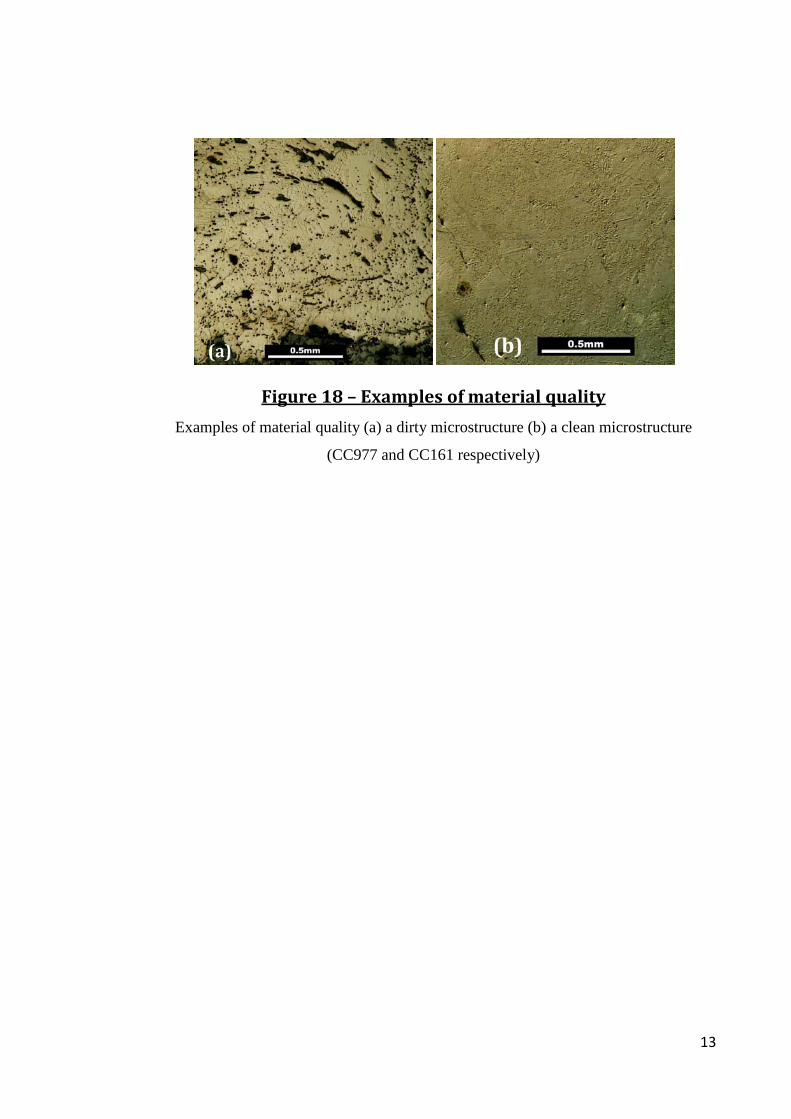
Figure 18 – Examples of material quality
Examples of material quality (a) a dirty microstructure (b) a clean microstructure
(CC977 and CC161 respectively)

14
Figure 19 – Examples of artefact classes
(a) Knife BN300 (b) Buckle SOU1073 (c) Nail Thet277A (d) Hook CC161 (e) Bar CC292

15
Figure 20 – Examples of section placements
(a)knife (b)belt (c)dress tab (d)nail (e)staple (f)bar

16
Figure 21 – SEM vs. EMPA analyses
A graph of Scanning Electron Microscope values vs. Electron Microprobe Analyses
values
Figure 22 – Grain boundary ghosting
(a) Ghosting with overlying current structure (red arrow) Thet203-5 (b) Ghosting along
the grain boundaries (red arrow) Thet248
y = 0.4474x + 0.0659
0.000
0.100
0.200
0.300
0.400
0.500
0.600
0.00 0.20 0.40 0.60 0.80 1.00
EMPA
(wt%
P)
SEM Data (wt%P)
SEM vs. EMPA

17
Figure 23 – Inter-granular ghosting
Inter-granular Ghosting (Image from WP95)
Figure 24 – Edge effect ghosting
Edge Effect Ghosting Where P-iron Meets Pearlite (red arrow)

18
Figure 25 – Slag inclusion ghosting in WP115
Grain Boundary Ghosting (red arrow) and Slag Inclusion Ghosting (green arrow)
Figure 26 – Pearlitic Ghosting in SOU99-92
Pearlitic Ghosting

19
Figure 27 – Map of the location Brent Knoll
(from
http://en.wikipedia.org/wiki/Template:Location_map_United_Kingdom_Somerset)

20
Figure 28 – Cross-section of nail BN310
A cross-section of nail BN310
(areas of hardness testing and other analyses are indicated; also indicated is the area
of high arsenic)
Table 15 Analysis results for nail BN310
(Hv# - The hardness test number corresponding the image above)
HV # Alloy type Vickers Hardness (Hv) SEM %P SEM %As ASTM Grain Size Notes Hv1 Ferrite 176 0.1 ± 0.1 0.1 ± 0.2 5
Hv2 Arsenical Iron 180 0.1 ± 0.1 0.40 ± 0.2 6
Etch Resistant
Hv3 Phosphoric Iron 257 0.7 ± 0.1 0.1 ± 0.2 6 Ghosted Hv4 Ferrite + Pearlite 0.4%C 184 nd 0.40 ± 0.2 n/a
Hv5 Weld-line 220 nd nd n/a Weld-line Hv6 Pearlite 274 0.1 ± 0.1 nd n/a
Hv7 Weld-line 187 nd 1.1 ± 0.2 8

21
Figure 29 – Cross-section of nail BN334
A cross-section of nail BN334 (areas of hardness testing and other analyses are
indicated)
Table 16 Analysis results for nail BN334
(Hv # - The hardness test number corresponding the image above; nd = not detected)
HV # Alloy type
Vickers Hardness
(Hv0.2) SEM %P SEM %As
ASTM Grain Size Notes
Hv1 Ferrite + Pearlite <0.1%C 148 0.1 ± 0.1 0.3 ± 0.2 8 Hv2 Pearlite + Ferrite 0.7%C 314 0.1 ± 0.1 0.5 ± 0.2 n/a Hv3 Ferrite 164 nd 0.2 ± 0.2 7 Ghosted
Hv4 Ferrite 219 nd 0.3 ± 0.2 6 Hv5 Phosphoric Iron 241 0.2 ± 0.1 0.6 ± 0.2 6 Etch Resistant
Hv6 Ferrite + Pearlite 0.1%C 278 0.1 ± 0.1 0.4 ± 0.2 8 Hv7 Pearlite + Ferrite 0.7%C 293 nd 0.5 ± 0.2 n/a

22
Figure 30 – Map of the location of Canterbury
(a) Map of Kent with Canterbury indicated (adapted from
http://en.wikipedia.org/wiki/File:Kent_outline_map_with_UK.png) (b) Map of
Canterbury AD1050 (Tatton-Brown 1992: 82)

23
Figure 31 – The cross-section of bar CC299
The cross-section of bar CC299 with areas of hardness testing and other analyses are
indicated.
Table 30 Analysis results for bar CC299
(Hv# - The hardness test number corresponding the image above)
Hv # Alloy Type
Vickers Hardness (Hv0.2)
SEM Wt%P
SEM Wt%As
ASTM Grain Size Notes
Hv 1 Phosphoric Iron 189 0.4 ± 0.1 0.7 ± 0.2 1 Slag Inclusion Ghosting +
Etch Resistant Hv 2 Phosphoric Iron 212 1.1 ± 0.1 nd 2 Etch Resistant Hv 3 Phosphoric Iron 174 0.6 ± 0.1 0.2 ± 0.2 4 Hv 4 Phosphoric Iron 173 0.8 ± 0.1 0.3 ± 0.2 1
Hv 5 Phosphoric Iron 159 0.4 ± 0.1 0.1 ± 0.2 1 Slag Inclusion and Alloy
Edge Effects

24
Figure 32 – Map of the location of Southampton
(a) Map of Southampton/Hamwic (Brisbane 1988: 102) (b) Location of Winchester in
Hampshire (from
http://en.wikipedia.org/wiki/File:Hampshire_outline_map_with_UK.png)

25
Figure 33 – Ghosting Structures in Southampton
Summary of ghosting structures in artefacts from Southampton
Figure 34 – The cross-section of knife SOU98-38
The cross-section of knife SOU98-38 with areas of hardness testing and other analyses
are indicated
Table 43 Analysis results for knife SOU98-38
(Hv# - The hardness test number corresponding the image above)
Hv # Alloy Type
Vickers Hardness
(Hv) SEM Wt%P SEM Wt%As
ASTM Grain Size Notes
HV1 Tempered Martensite 546 0.3 ± 0.1 0.0 - HV2 Fine Pearlite 348 0.1 ± 0.1 0.1 ± 0.2 - HV3 Weld-line 226 0.1 ± 0.1 3.1 ± 0.2 - HV4 Phosphoric Iron + Pearlite 0.3%C 196 0.2 ± 0.1 0.4 ± 0.2 7 HV5 Ferrite 140 0.1 ± 0.1 0.7 ± 0.2 4 Etch Resistant HV6 Phosphoric Iron + Pearlite 0.2%C 149 0.2 ± 0.1 0.4 ± 0.2 7 HV7 Phosphoric Iron 149 0.4 ± 0.1 0.2 ± 0.2 1 Ghosting
02468
101214
Num
ber o
f Art
efac
ts
Ghosting Structures in Southampton

26
Figure 35 –Map of the location of Thetford and the Brandon Road
excavation
(a)The placement of the Brandon Road excavation in Thetford (adapted from (Atkins
and Aileen 2002)) (b)Location of Thetford in Norfolk (from
http://en.wikipedia.org/wiki/File:Norfolk_outline_map_with_UK.png)

27
Figure 36 – Ghosting structures of Thetford
Summary of ghosting structures in artefacts from Thetford

28
Figure 37 – Map of the location of Wharram Percy
(a)Map of the Wharram Percy Excavation (Milne and Richards 1992: 4) (b) Location of
Wharram Percy in North Yorkshire (from
http://en.wikipedia.org/wiki/File:North_Yorkshire_outline_map_with_UK.png)

29
Figure 38 – Ghosting structures at Wharram Percy
Summary of ghosting structures in artefacts from Wharram Percy
02468
101214
% o
f Art
efac
ts
Ghosting Structures in Wharram Percy

30
Figure 39 – The cross-section of nail head WP218
A cross-section of the nail head WP218 with areas of analysis indicated.
Table 77 Analysis results for bar nail WP218
(Hv# - The hardness test number corresponding to the image above)
Hv # Alloy Type Vickers
Hardness (Hv0.2) SEM
Wt%P SEM
Wt%As ASTM Grain
Size Notes Hv1 Phosphoric Iron 151 0.3 ± 0.1 0.4 ± 0.2 7 Ghosting Hv2 Phosphoric Iron 155 0.2 ± 0.1 0.6 ± 0.2 4 Etch Resistant Hv3 Phosphoric Iron 230 0.3 ± 0.1 0.4 ± 0.2 5 Ghosting + Etch Resistant Hv4 Phosphoric Iron 219 0.2 ± 0.1 0.3 ± 0.2 3 Ghosting + Etch Resistant Hv5 Phosphoric Iron 258 0.3 ± 0.1 0.8 ± 0.2 5 elongated Ghosting + Etch Resistant Hv6 Phosphoric Iron 292 0.2 ± 0.1 0.6 ± 0.2 6 elongated Ghosting + Etch Resistant Hv7 Phosphoric Iron 262 0.2 ± 0.1 0.6 ± 0.2 6

31
Figure 40 – Map of the location of Winchester
(a)Map of Anglo-Saxon Winchester (Reynolds 1999: 89) (b)Location of Winchester in
Hampshire (from
http://en.wikipedia.org/wiki/File:Hampshire_outline_map_with_UK.png)

32
Figure 41 – Map of the location of Worcester
Worcester ((Dalwood and Edwards 2004: 19) (b)Map of Worcestershire (from
http://en.wikipedia.org/wiki/File:Worcestershire_outline_map_with_UK.png)

33
Figure 42 – Map of the location of York and of the layout of Jorvik
(a) Early Medieval maps of York (Hall 1994: 32) (b) Location of York in North Yorkshire
(from http://en.wikipedia.org/wiki/File:North_Yorkshire_outline_map_with_UK.png)

34
Figure 43 – Ghosting structures in York
Summary of ghosting structures in artefacts from Anglo-Scandinavian York
Figure 44 – The cross-section of spoon auger Yo9439
The cross-section of spoon auger Yo9439 with areas of test areas are indicated
0
1
2
3
4
5
6
Grain Boundary
Inter-granular Edge Effects Slag Inclusions Pearlitic
# of
Art
efac
ts
Ghosting Structures in York

35
Figure 45 – McDonnell’s (1992) results in terms of the classes
0102030405060708090
100
% Heat Treated % with P-iron % Ghosted
% o
f Art
efac
ts
Class Comparison From McDonnell's Results
Class 1
Class 2
Class 3
36
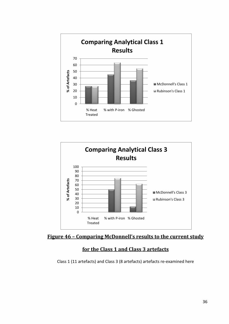
Figure 46 – Comparing McDonnell’s results to the current study
for the Class 1 and Class 3 artefacts
Class 1 (11 artefacts) and Class 3 (8 artefacts) artefacts re-examined here
0
10
20
30
40
50
60
70
% Heat Treated
% with P-iron % Ghosted
% o
f Art
efac
ts
Comparing Analytical Class 1 Results
McDonnell's Class 1
Rubinson's Class 1
0102030405060708090
100
% Heat Treated
% with P-iron % Ghosted
% o
f Art
efac
ts
Comparing Analytical Class 3 Results
McDonnell's Class 3
Rubinson's Class 3
37
Site
5th Century
AD
6th Century
AD
7th Century
AD
8th Century
AD
9th Century
AD
10th Century
AD
11th Century
AD Culture Brent Knoll
Saxon
Canterbury
Saxon York
Viking
Southampton
Saxon Worcester
Saxon
Thetford
Saxon Wharram
Percy
Saxon Winchester
Saxon
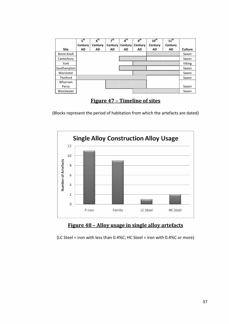
Figure 47 – Timeline of sites
(Blocks represent the period of habitation from which the artefacts are dated)
Figure 48 – Alloy usage in single alloy artefacts
(LC Steel = iron with less than 0.4%C; HC Steel = iron with 0.4%C or more)

38
Figure 49 – Single Alloy Construction Material Quality
Figure 50 – Use of heterogeneous iron in artefact construction
05
10152025303540
Single Bar Construction
Multi Bar Construction Component in Composite
Construction
Num
ber o
f Art
efac
ts
Heterogeneous Artefacts
0
20
40
60
80
100
Class 1 Class 2 Class 3
% o
f Cle
an A
rtef
acts
Class
Single Alloy Material Qualtiy
39
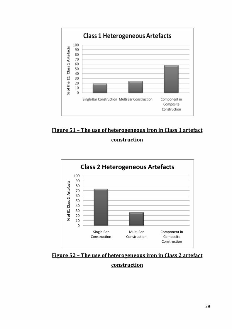
Figure 51 – The use of heterogeneous iron in Class 1 artefact
construction
Figure 52 – The use of heterogeneous iron in Class 2 artefact
construction
0102030405060708090
100
Single Bar Construction
Multi Bar Construction
Component in Composite
Construction
% o
f 31
Clas
s 2
Art
efac
ts
Class 2 Heterogeneous Artefacts
40
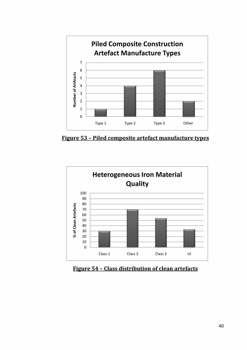
Figure 53 – Piled composite artefact manufacture types
Figure 54 – Class distribution of clean artefacts
0
1
2
3
4
5
6
7
Type 1 Type 2 Type 3 Other
Num
ber o
f Art
feac
ts
Piled Composite Construction Artefact Manufacture Types
0102030405060708090
100
Class 1 Class 2 Class 3 UI
% o
f Cle
an A
rtef
acts
Heterogeneous Iron Material Quality

41
Figure 55 – Edged tool composite construction artefacts
(35 artefacts total)
Figure 56 –Type 2 edged tool knife back construction
0
1
2
3
4
5
6
7
Single Alloy P-iron
Single Alloy Ferrite
Piled Heterogeneous
Heterogeneous
Num
ber o
f Art
efac
ts
Type 2 Knife Back Construction

42
Figure 57 – Alloy usage in Class 1 edged tools with composite
construction
Figure 58 –Material quality of alloys used in composite
construction artefacts
0
20
40
60
80
100
P-iron Ferrite Frt + Prlt Steel
% o
f Art
efac
ts
Alloy
Compact Construction Class 1 Edge Tools
0
20
40
60
80
100
P-iron Ferrite Frt + Prlt Steel% o
f Art
efac
t in
Whi
ch t
he A
lloy
Was
U
sed
Alloy
Material Quality of Composite Construction Alloys

43
Figure 59 – Average ferrite grain size per artefact
Figure 60 – Forms of ferritic iron used by early smiths
0
5
10
15
20
25
30
35
1 2 3 4 5 6 7 8
# of
Art
efac
ts
ASTM Grain Size
Ferrite Grain Size
0
10
20
30
40
50
60
Individual Alloy Heterogeneous Iron
# of
Art
efac
ts
Component Used in Artefact Construction
Ferritic Iron Used By Smith

44
Figure 61 - Composite artefacts where ferrite was used as an
individual alloy component
(the ‘Type 1 like’ artefacts were not edged tools)
Figure 62 – Percent of artefacts based on class with ferrite both as
individual alloy use and in heterogeneous iron
0
1
2
3
4
Type 1 Like Type 2 Type 3 Type 4 Pattern Welded
# of
Art
efac
ts
Knife Construction Typology
Composite Construction Typologies for Artefacts with Ferrite

45
Figure 63 –Cleanness of ferritic iron used as individual
components and in heterogeneous iron
Figure 64 –Number of artefacts containing each form of high
carbon steel
0
10
20
30
40
50
60
70
80
90
100
clean Dirty
% o
df A
rtef
acts
Cleanness of Ferritic iron
Individual Alloy
Heterogeneous Iron

46
Figure 65 –High carbon steel usage based on class and form
Figure 66 – The low carbon steel usage in the early medieval
artefacts
(Single Alloy = single alloy construction artefacts; Composite = composite construction
artefacts; Heterogeneous = low carbon steel in heterogeneous iron)
05
1015202530354045
Class 1 Class 2 Class 3 UI
# of
Art
efac
ts
Class
High Carbon Steel Usage Based on Class
Carburization
Heterogeneous Steel
Individual Alloy Used in Composite Artefacts
Single Alloy Construction

47
Figure 67 –Low carbon steel usage based on class and type of
manufacture

48
Figure 68 – Cross-sections of nail WP556
(a) etched with Nital (b) etched with Stead’s Reagent

49
Figure 69 – Carbon versus phosphorus in steels
(Minimum phosphorus content limited to 0.1wt%P)
0.0
0.1
0.2
0.3
0.4
0.5
0.6
0.7
0.8
0.9
0 0.2 0.4 0.6 0.8
Carb
on C
onte
nt (%
C)
Phosphorus Content (wt%P)
Phosphorus in Steel
50
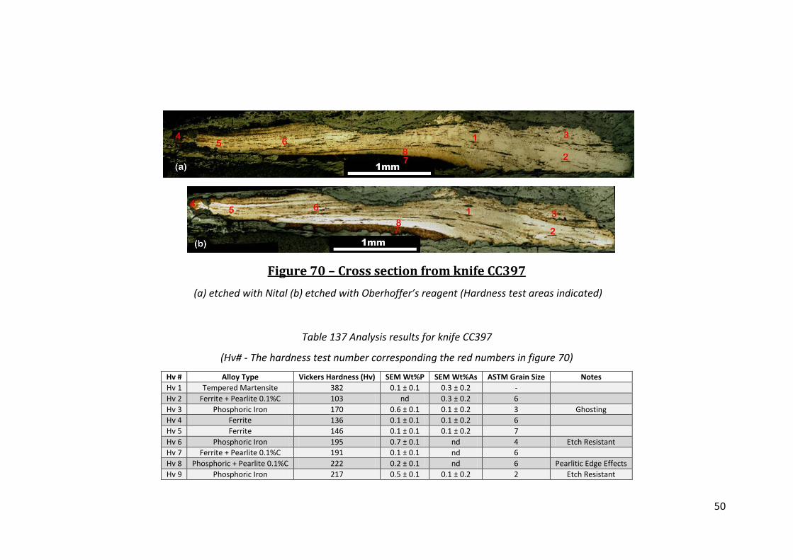
Figure 70 – Cross section from knife CC397
(a) etched with Nital (b) etched with Oberhoffer’s reagent (Hardness test areas indicated)
Table 137 Analysis results for knife CC397
(Hv# - The hardness test number corresponding the red numbers in figure 70)
Hv # Alloy Type Vickers Hardness (Hv) SEM Wt%P SEM Wt%As ASTM Grain Size Notes Hv 1 Tempered Martensite 382 0.1 ± 0.1 0.3 ± 0.2 -
Hv 2 Ferrite + Pearlite 0.1%C 103 nd 0.3 ± 0.2 6 Hv 3 Phosphoric Iron 170 0.6 ± 0.1 0.1 ± 0.2 3 Ghosting
Hv 4 Ferrite 136 0.1 ± 0.1 0.1 ± 0.2 6 Hv 5 Ferrite 146 0.1 ± 0.1 0.1 ± 0.2 7 Hv 6 Phosphoric Iron 195 0.7 ± 0.1 nd 4 Etch Resistant
Hv 7 Ferrite + Pearlite 0.1%C 191 0.1 ± 0.1 nd 6 Hv 8 Phosphoric + Pearlite 0.1%C 222 0.2 ± 0.1 nd 6 Pearlitic Edge Effects
Hv 9 Phosphoric Iron 217 0.5 ± 0.1 0.1 ± 0.2 2 Etch Resistant
51
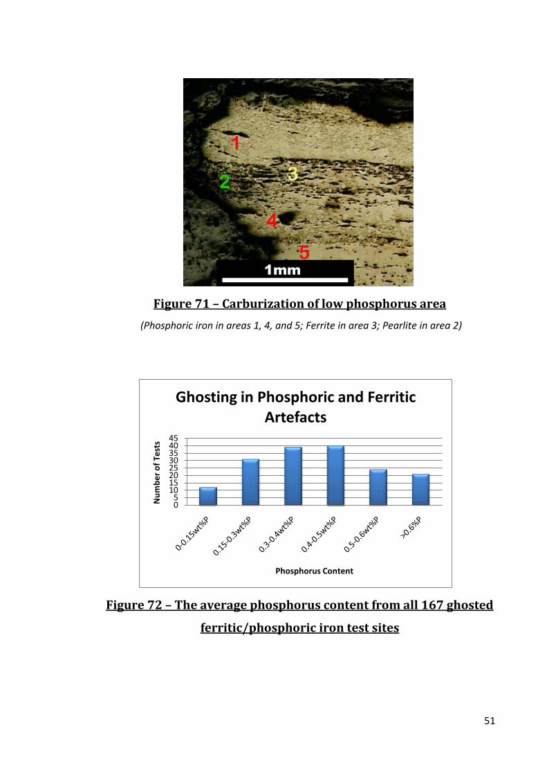
Figure 71 – Carburization of low phosphorus area
(Phosphoric iron in areas 1, 4, and 5; Ferrite in area 3; Pearlite in area 2)
Figure 72 – The average phosphorus content from all 167 ghosted
ferritic/phosphoric iron test sites
05
1015202530354045
Num
ber o
f Tes
ts
Phosphorus Content
Ghosting in Phosphoric and Ferritic Artefacts

52
Figure 73 – Ghosting and phosphorus content in nail WP556
(a) SEM secondary electron image of a ghosted phosphoric iron grain from nail WP556
with test sites indicated; (b) Phosphorus content at test sites

53
Figure 74 – Common Dubé forms including allotriomorphs
Figure 8.4.16
(A) and Widmanstätten-like structures (B1 & B2) (red arrow indicates grain boundary;
green arrow indicates Widmanstätten)
Figure 75 – SEM secondary electron image of grain boundary
ghosting structures with SEM/EDS phosphorus measurements
SEM secondary electron image of grain boundary ghosting with allotriomorphs (red
arrow) and Widmanstätten-like (blue arrow) structures as well as the SEM/EDS
phosphorus measurements
(Test areas indicated)

54
Figure 76 – Inter-granular ghosting as an edge effect in SOU31-
669
Figure 77 – SEM images of pearlitic ghosting in bar SOU31-814
(a) SEM secondary electron image of pearlitic ghosting in bar SOU31-814; (b)
magnified image of pearlitic ghosting (pearlite indicated)

55
Figure 78 – SEM images of pearlitic ghosting in knife SOU24-22
(a) SEM secondary electron image of pearlitic ghosting in knife SOU24-22 with test
sites indicated; (b) Phosphorus content at test sites
0.15
0.2
0.25
0.3
0.35
12345678
Phos
phor
us C
onte
nt (w
t%P)
Test Number
Pearlite Ghosting SOU24-22
(B)

56
Figure 79 – Slag inclusion ghosting in bar SOU31-814
Slag inclusion ghosting in bar SOU31-814 in a (a) secondary electron image from the
SEM and; (b) etched in Stead’s reagent where copper deposits in low phosphorus areas

57
Figure 80 – SEM secondary electron image of a ghosted slag
inclusion in bar SOU31-814
SEM secondary electron image of a ghosted slag inclusion in bar SOU31-814
(Tests areas indicated)
Table 141 Phosphorus analysis results for test areas indicated in Figure 8.2.12 from
SOU31-814
Area Description Test # Phosphorus (wt%P) Slag Inclusion (P2O5) 1 6.9
Inclusion Halo 2 0.3 Surrounding Grains 3 0.7
58
Figure 81 – Hardness values versus phosphorus content
Figure 82 –Harness values versus grain size
0.00
0.20
0.40
0.60
0.80
1.00
1.20
1.40
0 50 100 150 200 250 300 350
SEM
/ED
S Ph
osph
orus
Con
tent
(wt%
P)
Hardness Values (Hv0.2)
Hardness vs. Phosphorus Content
100
120
140
160
180
200
220
240
260
280
300
0 1 2 3 4 5 6 7 8 9
Har
dnes
s V
alue
(Hv0
.2)
Grain Size (ASTM)
Grain Size vs. Hardness Values

59
Figure 83 – Hardness values of ghosted phosphoric iron versus
hardness values of un-ghosted phosphoric iron
0
50
100
150
200
250
300
350
0 100 200 300 400
Har
dnes
s V
alue
s (h
v0.2
)
Number of Tests
Unghosted Hardness Values
0
50
100
150
200
250
300
350
0 50 100 150 200
Har
dnes
s V
alue
s (h
v0.2
)
Number of Tests
Ghosted Hardness Values
60
Figure 84 – Grain size distribution in phosphoric iron
artefacts
05
1015202530354045
1 2 3 4 5 6 7 8
Num
ber o
f Art
efac
ts
Grain Size (ASTM)
Phosphoric Iron Artefacts per Grain Size

61
Figure 85 – Grain size distribution of ferritic iron artefacts
Figure 86 – Grain size versus elemental composition
0.00
0.20
0.40
0.60
0.80
1.00
1.20
1.40
0 2 4 6 8
Phos
phor
us C
onet
net (
wt%
P)
Grain Size (ASTM)
Grain Size Vs. Phosphorus Content

62
Figure 87 – Phosphoric iron usage based on class and
construction
Figure 88 – Single alloy artefacts divided based on class
05
10152025303540
Class 1 Class 2 Class 3 UI
# of
Art
efac
ts
Class
Phosphoric Iron Usage Based on Class
Individual Alloy Component of Composite Construction
Component of Heterogeneous Iron
Carburized Single Alloy Objects
Single Alloy Objects
0
2
4
6
8
10
12
14
Ferrite Phosphoric Iron
Low Carbon Steel
High Carbon Steel
# of
Art
efac
ts
Alloy
Single Alloy Artefacts
Class 1
Class 2
Class 3
UI

63
Figure 89 – Individual alloy components of composite artefacts
divided based on class
05
10152025303540
Ferrite Phosphoric Iron
Low Carbon Steel
High Carbon Steel
# of
Art
efac
ts
Alloy
Individual Alloy Used in Composite Artefacts
Class 1
Class 2
Class 3
UI
01234567
Type 2 Type 3 Type 4 Type 5 Pattern Welded
Num
ber o
f Art
efac
ts
Manufacture Type
Heat treated Edge Tool Manufacture Types

64
Figure 90 – Manufacture types of heat-treated artefacts
(Typology can be found in Section 5.1)
Figure 91 – Construction techniques in Class 1 and Class 2
artefacts
65
Figure 92 – Alloy usage based on class
Figure 93 – Non-heterogeneous alloy usage
6760
5664
68
53
70
49
0
10
20
30
40
50
60
70
80
Class 1 (57 artefacts) Class 2 (53 artefacts)
% o
f Art
efac
ts
Alloy Usage in Class 1 and Class 2 Artefacts
P-iron
Ferrite
LC Steel
HC Steel
23
13
21 21
39
15
58
17
0
10
20
30
40
50
60
70
80
Class 1 (57 artefacts) Class 2 (53 artefacts)
% o
f Art
efac
ts
Non-heterogeneous Alloy Usage
P-iron
Ferrite
LC Steel
HC Steel

66
Figure 94 – Manufacture of the Class 3 artefacts
Figure 95 – Overall alloy usage for Class 3 artefacts
P-iron 34%
Ferrite 28%
LC Steel21%
HC Steel17%
Class 3 Alloy Usage
67
Figure 96 – Single alloy Class 3 artefacts
Figure 97 – Cleanness of the Class 1 artefacts
01020304050607080
Dress Fittings Edged Tools Other Tools Security Weapons
% o
f Art
efac
ts
Artefact Catagories
Class 1 Artefact Cleanness
67%
33%
0% 0%
Class 3 Single Alloy Artefacts
P-iron
Ferrite
LC Steel
HC Steel

68
Figure 98 – Comparing the cleanness of the three classes
Class 1 (57 artefacts)
Class 2 (53 artefacts)
Class 3 (27 artefacts)
59 69 59
41 31 41
Cleanness Based on Class% Clean % Dirty

69
Figure 99 – Artefact manufacturing typology based on cross-sections
(adapted from Tylecote and Gilmour, 1986). 0F = all ferrite , 0P = all phosphoric iron, 1 = steel core flanked by ferritic or phosphoric iron, 2 =
steel edge welded to the iron back, 3 = piled or banded structure throughout the section, 4W = a welded steel jacket around an iron core, 4C=a
carburized layer outside a iron core, 5 = all steel, 6 = pattern welded, 7 = heterogeneous (The term steel in this figure can be either high carbon
or low carbon steel)

70
Figure 100 - Map of sites
(green = rural; red = urban)
Figure 101 – Artefact construction from all sites

71
Figure 102 – Manufacture by site
(The Winchester assemblage was not included due to it only containing 4 composite knives)

72
Figure 103 – Comparing Class 1 and Class 2 manufacture

73
Figure 104 – A comparison of overall alloy usage in the archaeological sites

74
Figure 105 – A comparison of non-heterogeneous alloy usage in the archaeological site

75
Figure 106 – Cleanness of iron by site
8057 63 53 53
75 8354
2043 37 47 47
25 1746
Cleanness of Iron
% Clean % Dirty

76
Tables
Table 1 – Hardness values for phases of carbon-iron alloys
Mean hardness values of different phases observed in microstructures of cutting edge
from Early British Iron Edge tools
(Wiemer, 1993: Appendix IV)
Microstructure (cutting edge) Hardness Hv0.1 Tempered Martensite 627
Pearlite 319 Spherodised Carbides 296
Phosphoric Iron 192 Ferrite 100
Table 2 – Heat-treatment at Early Medieval settlement sites
Occurrence of high carbon steel, heat-treatment and use as complete objects in Early
Medieval settlement sites
(Data taken from McDonnell, 1992, 1987a, and 1987b)
Site # Knives % Containing Steel % Heat Treated % Completely Steel Coppergate, York 47 91 60 4
Southampton 14 93 64 7 Fishergate,
York 10 100 60 0
77
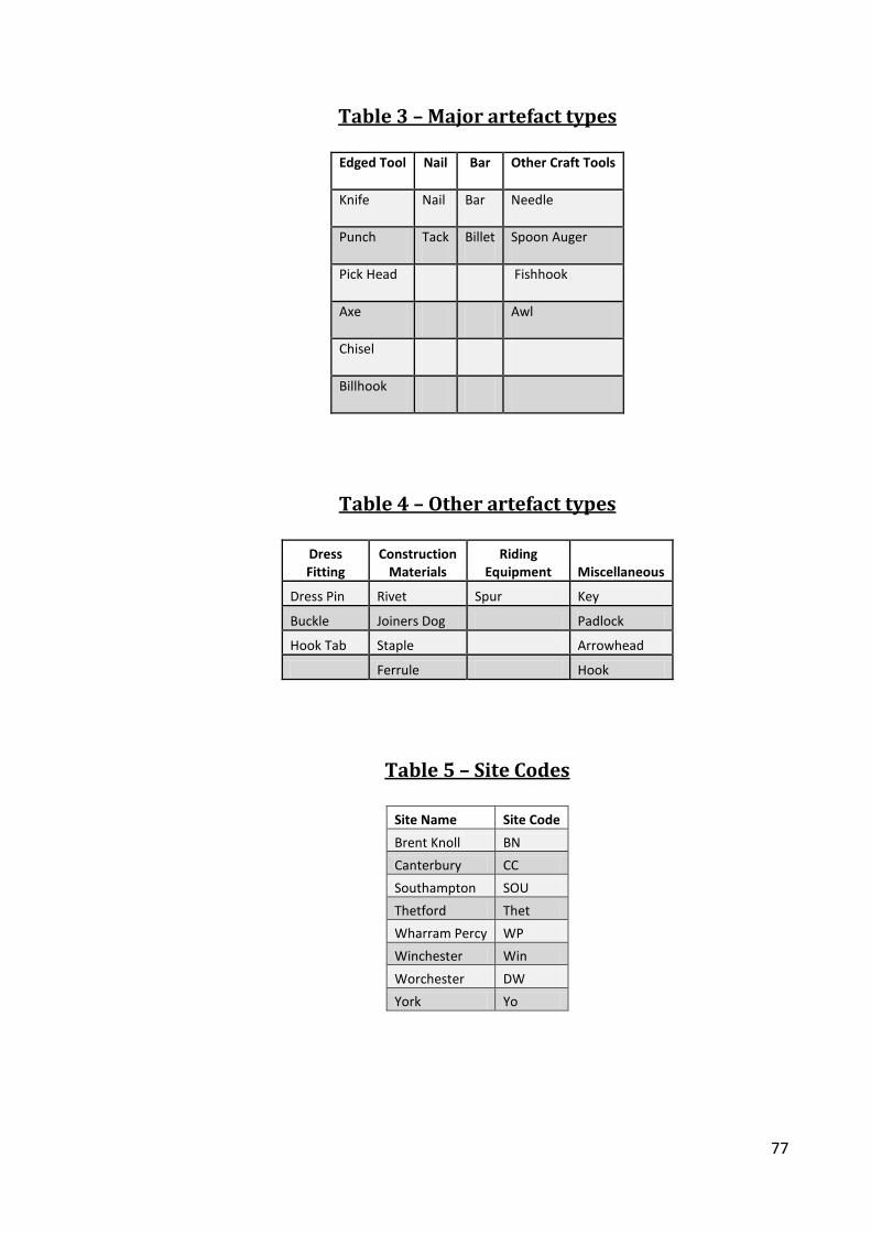
Table 3 – Major artefact types
Edged Tool Nail Bar Other Craft Tools
Knife Nail Bar Needle
Punch Tack Billet Spoon Auger
Pick Head Fishhook
Axe Awl
Chisel
Billhook
Table 4 – Other artefact types
Dress Fitting
Construction Materials
Riding Equipment Miscellaneous
Dress Pin Rivet Spur Key
Buckle Joiners Dog Padlock
Hook Tab Staple Arrowhead
Ferrule Hook
Table 5 – Site Codes
Site Name Site Code
Brent Knoll BN
Canterbury CC
Southampton SOU
Thetford Thet
Wharram Percy WP
Winchester Win
Worchester DW
York Yo

78
Table 6 – Results of SEM and EMPA analyses
Yo26736 W115 Thet 427
Test # SEM
(wt%P) EMPA
(wt%P) Test # SEM P (wt%P)
EMPA (wt%P) Test #
SEM (wt%P)
EMPA (wt%P)
Test 1 0.00 0.020 Test1 0.17 0.243 Hv1 Test 2 0.55 0.506 Test 2 0.05 0.020 Test2 0.45 0.262 Hv1 Test 3 0.23 0.166 Test 3 0.06 0.029 Test3 0.39 0.267 HV2 Test 1 0.21 0.184 Test 4 0.13 0.018 Test4 0.27 0.259 Hv3 Test1 0.07 0.172 Test 5 0.09 0.017 Test5 0.78 0.262 Hv3 Test 2 0.19 0.218 Test 6 0.05 0.021 Test6 0.88 0.425 Hv3 Test 3 0.17 0.136
Test7 0.49 0.240 Hv4 Test 1 0.19 0.089 Test8 0.50 0.284 Hv4 Test 2 0.19 0.190 Test9 0.43 0.412 Hv4 Test 3 0.40 0.088 Test10 0.20 0.200 Hv4 Test 4 0.23 0.283
Table 7 – Summary of Brent Knoll artefacts
Artefact #
Artefact Type Class
Period (centuries
AD) Context Dimensions
(mm) Weight
(g)
# Sections
Taken Section
Placement Class 1
300 Knife 1 11th Fill/Pit 115x19x12 34 2 Knife back and cutting edge
301 Knife 1 10th-11th Layer 138x18x17 44 2 Knife back and cutting edge
324 Dress Pin 1 10th-11th Fill/Structure 49x5x5 3 1 Cross section of
thicker end
329 Punch 1 12th Layer 71x8x8 17 1 Cross section of
tip
333 Arrowhead 1 11th Layer/Structure
Interior 84x15x12 18 1 Cross section of
thicker end Class 2
305 Hook 1 10th-11th Fill/Ditch/Structure
Interior 85x45x15 49 2
Longitudinal section of point
and cross section of ball end
310 Nail 2 10th-11th Layer/Structure
Interior 40x19x8 7 1 Cross section of
shank
317 Nail 2 11th Layer 35x7x6 10 1 Cross section of
shank
334 Nail Tip 2 11th Soil above Interior
Hearth 25x4x4 10 1 Longitudinal
section of point Class 3
311 Tapering Iron Bar 3 11th
Ash in Interior Hearth 45x18x10 20 2
Cross section of thick end and longitudinal section of
tapered end

79
Table 8 – Class 1 alloy summary for Brent Knoll
(Numbers are based on the number of artefacts in the category with the alloy present
and how much of the alloy was present)
The Amount of the Section with the Alloy P-iron Ferrite
LC Steel HC Steel
Heat Treated Steel
# Artefacts w/ alloy 3 2 2 3 1 Whole object 1 0 0 1 0 More than1/2 of the object 1 0 1 0 0 Up to 1/2 of the object 1 2 1 2 1

80
Table 9 – Brent Knoll Class 1 artefact analyses
(Hv0.2 and grain size measurements are averaged; %C is estimated; n/a = not applicable)
Artefact
#
Artefact
Type Description of Microstructure
P-Iron
Hv0.2
Ferrite
Hv0.2
LC Steel
Hv0.2
LC Steel
%C
HC Steel
Hv0.2
Ferrite Grain
Size (ASTM)
P-iron Grain
Size (ASTM) Clean?
Heat
Treated
Class 1
300 Knife
A type 1 knife with a spherodised carbide pearlitic
steel band encased in a phosphoric iron back 165 n/a 192 0.3 193 n/a 5 Dirty No
301 Knife
A type 4 knife with a martensitic outer shell welded
on ferritic core with extensive carbon diffusion n/a 160 186 0.4 317 6 n/a Clean No
324 Dress Pin
Completely composed of phosphoric iron with mild
ghosting 200 n/a n/a n/a n/a n/a 5 Clean No
329 Punch
Composed of HC steel in the form of partially
spherodised carbide n/a n/a n/a n/a 210 n/a n/a Clean No
333 Arrowhead
Composed of heterogeneous phosphoric iron with
small area that is ferritic iron 162 111 n/a n/a n/a 7 6 Dirty No
81
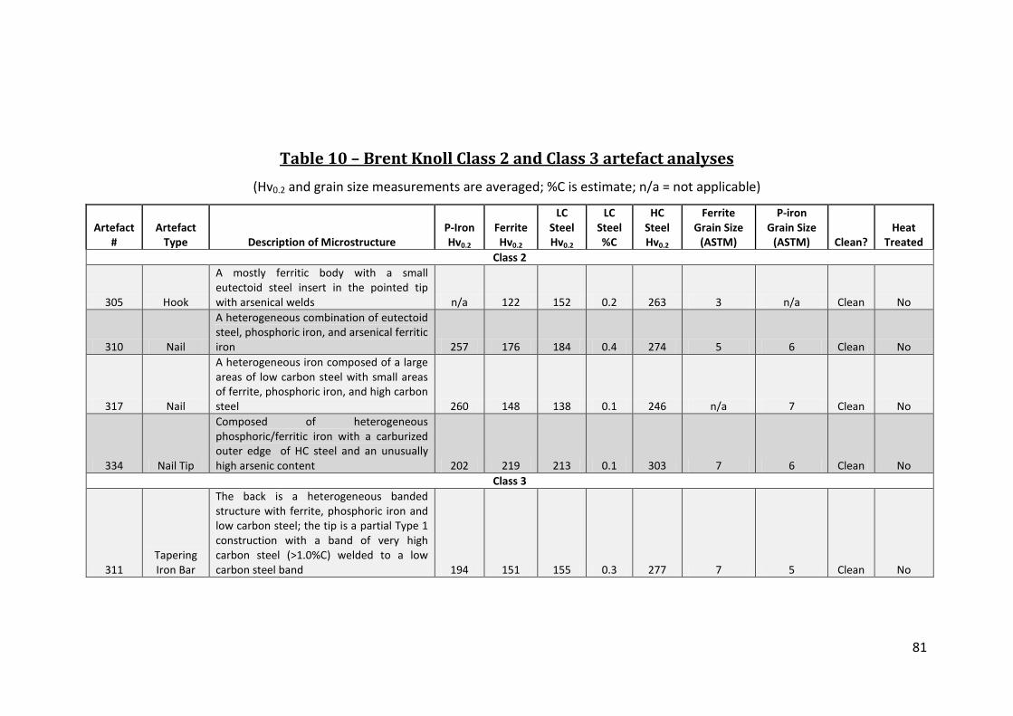
Table 10 – Brent Knoll Class 2 and Class 3 artefact analyses
(Hv0.2 and grain size measurements are averaged; %C is estimate; n/a = not applicable)
Artefact #
Artefact Type Description of Microstructure
P-Iron Hv0.2
Ferrite Hv0.2
LC Steel Hv0.2
LC Steel %C
HC Steel Hv0.2
Ferrite Grain Size
(ASTM)
P-iron Grain Size
(ASTM) Clean? Heat
Treated Class 2
305 Hook
A mostly ferritic body with a small eutectoid steel insert in the pointed tip with arsenical welds n/a 122 152 0.2 263 3 n/a Clean No
310 Nail
A heterogeneous combination of eutectoid steel, phosphoric iron, and arsenical ferritic iron 257 176 184 0.4 274 5 6 Clean No
317 Nail
A heterogeneous iron composed of a large areas of low carbon steel with small areas of ferrite, phosphoric iron, and high carbon steel 260 148 138 0.1 246 n/a 7 Clean No
334 Nail Tip
Composed of heterogeneous phosphoric/ferritic iron with a carburized outer edge of HC steel and an unusually high arsenic content 202 219 213 0.1 303 7 6 Clean No
Class 3
311 Tapering Iron Bar
The back is a heterogeneous banded structure with ferrite, phosphoric iron and low carbon steel; the tip is a partial Type 1 construction with a band of very high carbon steel (>1.0%C) welded to a low carbon steel band 194 151 155 0.3 277 7 5 Clean No

82
Table 11 – Class 2 alloy usage for Brent Knoll
(Numbers are based on the number of artefacts in the category with the alloy present
and how much of the alloy was present)
The Amount of the Section with the Alloy P-iron Ferrite LC Steel HC Steel
Heat Treated Steel
# Artefacts w/ alloy 1 1 1 1 0 Whole object 0 0 0 0 0 More than1/2 of the object 0 0 0 0 0 Up to 1/2 of the object 1 1 1 1 0
Table 12 – Class 3 alloy usage for Brent Knoll
(Numbers are based on the number of artefacts in the category with the alloy present
and how much of the alloy was present)
The Amount of the Section with the Alloy P-iron Ferrite LC Steel HC Steel
Heat Treated Steel
# Artefacts w/ alloy 1 1 1 1 0 Whole object 0 0 0 0 0 More than1/2 of the object 0 0 0 0 0 Up to 1/2 of the object 1 1 1 1 0
Table 13 – Phosphorus in Steel in the Brent Knoll assemblage
(Measurements are from individual test sites with estimated carbon content)
Artefact #
Artefact Type
High Carbon
Steel wt%P
High Carbon
Steel Hv0.2
High Carbon
Steel %C Placement P-iron in Artefact?
Heat Treated?
BN301 Knife 0.18 193 0.4 Back of knife
back No No
BN311 Tapering Iron
Bar 0.12 263 >0.8 Knife tip Yes No BN329 Punch 0.12 210 0.6 In cross-section No No

83
Table 14 – Data on the phosphoric iron in the Brent Knoll assemblage
(n/a = not applicable; nd = not detected)
Artefact # Artefact Type
Placement within Artefact Ghosting Structures
# P-iron Areas Analyzed
Data Type
P-iron (ave.
wt%P) Ghosting? Etch
Resistance? Grain Size
(ave. ASTM) P-iron
ave. Hv0.2 Class 1
300 Knife Knife back and sides Inter-granular; Widmanstätten
like 4
Mean 0.33 Yes Yes 5 165 Low 0.25 No No 6 142 High 0.39 Yes Yes 2 173
301 Knife nd n/a nd Mean nd No No n/a n/a
324 Dress Pin Through out Inter-granular & GB 3
Mean 0.54 Yes Yes 5 200 Low 0.40 Yes No 6 169 High 0.68 No Yes 5 212
329 Punch nd n/a nd Mean nd No No n/a n/a
333 Arrowhead Most of the structure Slag inclusion & inter-granular;
Some Widmanstätten like 3
Mean 0.57 Yes No 6 162 Low 0.52 Yes No 6 154 High 0.65 No No 5 175
Class 2 305 Hook nd n/a nd Mean nd No No n/a n/a
310 Nail Small corner of the
section Slag inclusion & EE; Ripple like 1 Mean 0.66 Yes Yes 6 257
317 Nail A small area in
heterogeneous structure n/a 1 Mean 0.2 No No 7 260
334 Nail Tip In heterogeneous
structure Inter-granular; Ripple like 1 Mean 0.23 Yes Yes 6 202 Class 3
311 Tapering Iron
Bar In heterogeneous section
from thick end GB, EE, & Slag inclusion; Ripple
like 5
Mean 0.40 No No 5 194 Low 0.16 No No 7 159 High 0.80 No No 4 210

84
Table 15 – Analysis of nail BN310
(Hv# - The hardness test number corresponding the Figure 28)
HV # Alloy type
Vickers Hardness (Hv0.2) SEM %P SEM %As
ASTM Grain Size Notes
Hv1 Ferrite 176 0.1 ± 0.1 0.1 ± 0.2 5
Hv2 Arsenical Iron 180 0.1 ± 0.1 0.40 ± 0.2 6 Etch
Resistant
Hv3 Phosphoric
Iron 257 0.7 ± 0.1 0.1 ± 0.2 6 Ghosted
Hv4
Ferrite + Pearlite 0.4%C 184 nd 0.40 ± 0.2 n/a
Hv5 Weld-line 220 nd nd n/a Weld-line Hv6 Pearlite 274 0.1 ± 0.1 nd n/a
Hv7 Weld-line 187 nd 1.1 ± 0.2 8
Table 16 – Analysis of nail BN334
(Hv # - The hardness test number corresponding the Figure 29; nd = not detected)
HV # Alloy type
Vickers Hardness
(Hv0.2) SEM %P SEM %As ASTM
Grain Size Notes
Hv1 Ferrite + Pearlite <0.1%C 148 0.1 ± 0.1 0.3 ± 0.2 8
Hv2 Pearlite + Ferrite 0.7%C 314 0.1 ± 0.1 0.5 ± 0.2 n/a Hv3 Ferrite 164 nd 0.2 ± 0.2 7 Ghosted Hv4 Ferrite 219 nd 0.3 ± 0.2 6
Hv5 Phosphoric Iron 241 0.2 ± 0.1 0.6 ± 0.2 6 Etch Resistant
Hv6 Ferrite + Pearlite 0.1%C 278 0.1 ± 0.1 0.4 ± 0.2 8 Hv7 Pearlite + Ferrite 0.7%C 293 nd 0.5 ± 0.2 n/a

85
Table 17 – Manufacture summary for the Brent Knoll artefacts
# Total Artefacts # Class 1 Artefacts # Class 2 Artefacts # Class 3 Artefacts # Total Artefacts 10 5 4 1 Evidence of Cold Working 0 0 0 0 Heat Treated 1 1 0 0 Carburized 2 0 2 0 Piled 1 0 0 1 Composite Construction 4 2 1 1 Single Alloy Construction 2 2 0 0 Heterogeneous 5 1 3 1 Clean 8 3 4 1
Table 18 – Alloy usage summary for class comparison in the Brent
Knoll assemblage
(Numbers are based on the number of artefacts in the category)
Alloy Usage # Total Artefacts P-iron Ferrite LC Steel HC Steel Heat Treated Steel Class 1 5 3 2 2 3 1 Class 2 4 3 4 4 4 0 Class 3 1 1 1 1 1 0 Total 10 7 7 7 8 1
Table 19 – Alloy usage summary for the Brent Knoll assemblage
(Numbers are based on the number of artefacts in the category with the alloy present
and how much of the alloy was present)
The Amount of the Section with the Alloy P-iron Ferrite LC Steel HC Steel Heat Treated Steel # Artefacts w/ alloy 7 7 7 8 1 Whole object 1 0 0 1 0 More than1/2 of the object 1 1 2 0 0 Up to 1/2 of the object 5 6 5 7 1
Table 20 – Cleanness of the Brent Knoll assemblage
% Total
Artefacts % Class 1 Artefacts
% Class 2 Artefacts
% Class 3 Artefacts
Clean 53 45 50 100

86
Table 21 – Summary description of the iron artefacts from Canterbury
(n/a = not applicable)
Artefact # Artefact Type Period (centuries AD) Context Dimensions (mm) Weight (g) # Sections Taken Section Placement Class 1
161 Fishhook 8th-9th n/a 82x2 5 1 Cross section of the back of the hook 213 Tab 8th-9th n/a 25x7x2 <1 1 Cross section of hook end 258 Needle 8th-9th n/a 45x1x1 <1 1 Longitudinal section of needle 357 Buckle 8th-9th n/a 28x11x4 6 1 Cross section of ring 397 Knife 8th-9th n/a 22x38x6 12 1 Cross section of blade 829 Knife 8th-9th n/a 84x24x8 26 1 Cross section of blade
211 Key Key 8th-9th n/a 44x15x6 12 1 Cross section of the pronged end 48-447 Knife 8th-9th n/a 37x14x2 8 1 Cross section of blade
Class 2 43 Staple 8th-9th n/a 20x22x5 6 1 Cross section of one prong
211 Nail 8th-9th n/a 37x9x5 5 2 Cross sections of head and tip 214 Fitting 8th-9th n/a 50x14x5 10 1 Cross section of back 230 Staple 8th-9th n/a 25x6x4 5 1 Cross section of prong 324 Tack 8th-9th n/a 13x6x3 1 1 Complete longitudinal section 359 Staple 8th-9th n/a 55x30x10 20 2 Cross section and longitudinal section of prong 418 Nail 8th-9th n/a 22x11x7 3 1 Cross section of head
Class 3 292 Bar/strip 8th-9th n/a 7x59x3 5 1 Cross section of bar 299 Bar 8th-9th n/a 3x31x10 6 1 Cross section of bar 363 Bar 8th-9th n/a 10x49x7 6 1 Cross section of bar 977 Billet 8th-9th n/a 3x35x10 10 1 Cross section of billet

87
Table 22 – Canterbury Class 1 artefact analyses
(Hv0.2 and grain size measurements are averaged; %C is estimated)
Artefact # Description Description of Microstructure
P-Iron Hv0.2
Ferrite Hv0.2
LC Steel Hv0.2
LC Steel %C
HC Steel Hv0.2
Ferrite Grain Size
(ASTM)
P-iron Grain Size
(ASTM) Clean? Heat
Treated Class 1
213 Hook Tag Completely ferritic iron n/a 169 n/a n/a n/a 1 n/a Dirty No
258 Needle
Phosphoric iron with a little grain boundary pearlite. Grains were elongated with minor ghosting 156 n/a n/a n/a n/a n/a 6 Clean No
357 Buckle Heterogeneous phosphoric iron with a small area of high carbon steel on one of the edges 201 n/a n/a n/a n/a n/a 1 Clean No
397 Knife
A type 4 construction with a phosphoric banded core surrounded a tempered martensite/bainite outer casing; there was significant carbon diffusion into the central bands 157 n/a n/a n/a 463 n/a 3 Clean Yes
829 Knife
A type 2 construction with a pearlitic tip with no clear weld to a banded phosphoric/ferritic back 194 141 147 0.1 382 7 4 Dirty No
211 Key Key A piled structure of mostly phosphoric iron with slight carburization along one edge 166 113 133 0.1 n/a 6 2 Dirty No
48-447 Knife
A type 4 construction with a phosphoric iron core with a pearlite edged tip and a line of pearlite width wise across the section not far from the tip 115 n/a n/a n/a 212 n/a 4 Clean No

88
Table 23 – Canterbury Class 2 artefact analysis
(Hv0.2 and grain size measurements are averaged; %C is estimated; n/a = not applicable)
Artefact # Description Description of Microstructure
P-Iron Hv0.2
Ferrite Hv0.2
LC Steel Hv0.2
LC Steel %C
HC Steel Hv0.2
Ferrite Grain Size
(ASTM)
P-iron Grain Size
(ASTM) Clean? Heat
Treated Class 2
43 Staple
A heterogeneous microstructure mostly phosphoric iron, ferrite with carburized edges 224 164 130 0.3 324 4 4 Clean No
161 Fishhook Almost completely composed of phosphoric iron 183 157 n/a n/a n/a 4 2 Dirty No
211 Nail A phosphoric iron with an large area of high carbon steel welded to one side 187 n/a n/a n/a 268 n/a 4 Dirty No
214 Fitting
A band of phosphoric iron that has been folded with slight carburization along the inside of the fold 215 n/a n/a n/a 257 n/a 4 Dirty No
230 Staple A folded banded structure of phosphoric and ferritic iron 169 133 n/a n/a n/a 6 5 Clean No
324 Tack
Phosphoric iron, the shank has large ghosted equiaxed grains while in the head the grains and ghosting elongated across the top 169 n/a n/a n/a n/a n/a 5 Clean No
359 Staple The structure is mostly phosphoric iron carburized along the outside 181 138 n/a n/a 177 n/a 5 Clean No
418 Nail A completely ferritic structure n/a 86 n/a n/a n/a 4 n/a Clean No
89
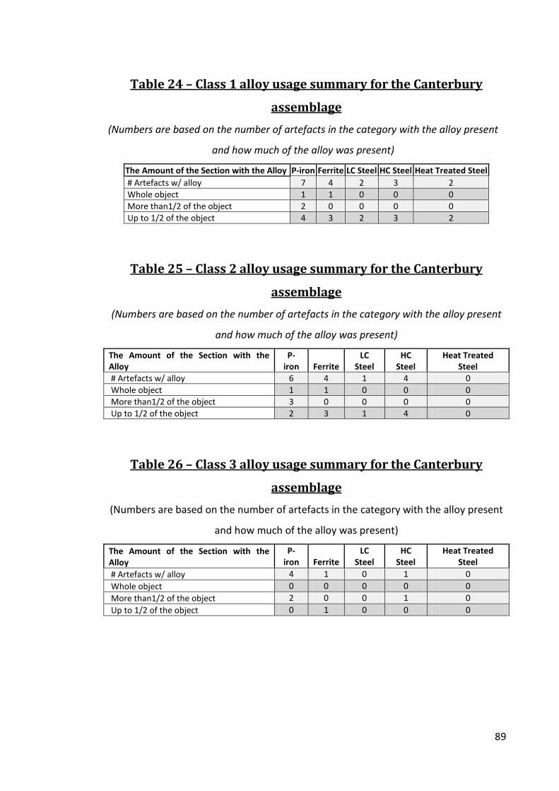
Table 24 – Class 1 alloy usage summary for the Canterbury
assemblage
(Numbers are based on the number of artefacts in the category with the alloy present
and how much of the alloy was present)
The Amount of the Section with the Alloy P-iron Ferrite LC Steel HC Steel Heat Treated Steel # Artefacts w/ alloy 7 4 2 3 2 Whole object 1 1 0 0 0 More than1/2 of the object 2 0 0 0 0 Up to 1/2 of the object 4 3 2 3 2
Table 25 – Class 2 alloy usage summary for the Canterbury
assemblage
(Numbers are based on the number of artefacts in the category with the alloy present
and how much of the alloy was present)
The Amount of the Section with the Alloy
P-iron Ferrite
LC Steel
HC Steel
Heat Treated Steel
# Artefacts w/ alloy 6 4 1 4 0 Whole object 1 1 0 0 0 More than1/2 of the object 3 0 0 0 0 Up to 1/2 of the object 2 3 1 4 0
Table 26 – Class 3 alloy usage summary for the Canterbury
assemblage
(Numbers are based on the number of artefacts in the category with the alloy present
and how much of the alloy was present)
The Amount of the Section with the Alloy
P-iron Ferrite
LC Steel
HC Steel
Heat Treated Steel
# Artefacts w/ alloy 4 1 0 1 0 Whole object 0 0 0 0 0 More than1/2 of the object 2 0 0 1 0 Up to 1/2 of the object 0 1 0 0 0

90
Table 27 – Canterbury Class 2 artefact analysis
(Hv0.2 and grain size measurements are averaged; %C is estimated; n/a = not applicable)
Artefact #
Artefact Type Description of Microstructure
P-Iron Hv0.2
Ferrite Hv0.2
LC Steel Hv0.2
LC Steel %C
HC Steel Hv0.2
Ferrite Grain Size (ASTM)
P-iron Grain Size (ASTM) Clean?
Heat Treated
292 Bar/strip A mostly ghosted phosphoric iron structure 229 220 n/a n/a n/a 4 1 Clean No
299 Bar
Two phosphoric bands each folded into themselves with heavy ghosting on the edges of the folds with a small amount of grain boundary pearlite along the outer edge 182 n/a n/a n/a n/a n/a 2 Clean No
363 Bar Two bands welded together, one phosphoric iron and the other 0.4%C steel 116 n/a n/a n/a 133 n/a 3 Clean No
977 Billet Completely phosphoric iron 176 n/a n/a n/a n/a n/a 3 Clean No

91
Table 28 – Phosphoric iron analyses for the Class 1 artefacts from the Canterbury assemblage
(Phosphorus content and hardness values averaged per test site; nd = not detected; n/a = not applicable)
Artefact #
Artefact Type
Location within Artefact
Ghosting Structures
# P-iron Areas Analyzed
Data Type
P-iron (ave.
wt%P) Ghosting? Etch
Resistance? Grain Size
(ave. ASTM)
P-iron (ave. Hv0.2)
Class 1 213 Tab nd Slag inclusion nd Mean nd Yes No n/a n/a
258 Needle Throughout Elongated; No
structures visible 2
Mean 0.34 Yes No 6 156 Low 0.25 No No 6 238 High 0.42 Yes No 6 230
357 Buckle Throughout GB & Slag inclusion 4
Mean 0.55 Yes No 1 201 Low 0.35 Yes No 1 178 High 0.78 No No 1 258
397 Knife The central band/back
of the knife GB & Slag inclusion 4
Mean 0.44 Yes No 3 157 Low 0.34 No No 2 140 High 0.58 Yes No 2 160
829 Knife Thin bands in the piled
microstructure n/a 3
Mean 0.6 No Yes 4 194 Low 0.51 No Yes 2 217 High 0.74 No Yes 4 195
211Key Key Thin bands in the piled
microstructure GB & Slag inclusion 4
Mean 0.44 Yes Yes 2 166 Low 0.26 Yes No 2 158 High 0.53 No Yes 3 173
48-447 Knife The core and back of
the knife Slag inclusion,
Pearlite, GB, &EE 3
Mean 0.36 Yes Yes 4 156 Low 0.26 No No 5 123 High 0.52 No Yes 3 186

92
Table 28 (cont.) – Phosphoric iron analyses for the Class 2 artefacts from the Canterbury assemblage
(Phosphorus content and hardness values averaged per test site; nd = not detected; n/a = not applicable)
Artefact #
Artefact Type Location within Artefact Ghosting Structures
# P-iron Areas
Analyzed Data Type
P-iron (ave.
wt%P) Ghosting? Etch
Resistance? Grain Size
(ave. ASTM)
P-iron ave. Hv0.2
Class 2
43 Staple Heterogeneously within
the section Inter-granular;
Ripple-like 2
Mean 0.42 Yes Yes 4 194 Low 0.37 Yes Yes 3 231 High 0.47 Yes No 4 217
161 Fishhook Almost all the composition Slag inclusions & GB 4
Mean 0.46 Yes No 2 183 Low 0.25 No No 5 148 High 0.66 Yes No 1 190
211 Nail
Most of the heterogeneous microstructure
Inter-granular, Pearlite & EE; Ripple-
like 4
Mean 0.47 Yes Yes 4 187 Low 0.4 Yes No 6 171 High 0.62 Yes No 3 168
214 Fitting Almost all the composition
Slag Inclusion & Inter-granular;
Ripple-like 3
Mean 0.32 Yes Yes 4 215 Low 0.22 Yes No 3 246 High 0.46 Yes No 4 210
230 Staple Heterogeneous bands Inter-granular;
Ripple-like 2
Mean 0.4 Yes Yes 5 169 Low 0.38 Yes No 5 156 High 0.42 Yes No 4 181
324 Tack Throughout Elongated; No
structure visible 5
Mean 0.4 Yes Yes 5 169 Low 0.25 No No 5 142 High 0.57 Yes No 6 191
359 Staple Most of the staple GB & Slag inclusion 3
Mean 0.5 Yes Yes 5 181 Low 0.5 Yes No 4 179 High 0.53 No No 5 187
418 Nail nd n/a nd Mean nd no Yes n/a n/a

93
Table 28 (cont.) – Phosphoric iron analyses for the Class 3 artefacts from the Canterbury assemblage
(Phosphorus content and hardness values averaged per test site; nd = not detected; n/a = not applicable)
Artefact #
Artefact Type
Location within Artefact Ghosting Structures
# P-iron Areas Analyzed
Data Type
P-iron (ave.
wt%P) Ghosting? Etch
Resistance? Grain Size
(ave. ASTM)
P-iron ave. Hv0.2
Class 3
292 Bar/strip Almost all the composition
Inter-granular & Slag inclusion 3
Mean 0.38 Yes Yes 1 229 Low 0.19 No No 2 167 High 0.49 Yes No 1 267
299 Bar Throughout
Slag inclusion, inter-granular, & GB; needle-
like 5
Mean 0.65 Yes Yes 2 182 Low 0.37 Yes Yes 1 189 High 1.13 No Yes 2 212
363 Bar
Half the microstructure; one
band Pearlite & Inter-
granular; Ripple-like 2
Mean 0.26 Yes No 3 119 Low 0.26 Yes No 3 121 High 0.27 No No 3 116
977 Billet Throughout Inter Granular & GB;
Elongation 5
Mean 0.42 Yes Yes 3 176 Low 0.17 No No 5 166 High 0.81 No No 1 204

94
Table 29 – Phosphorus in steel in the Canterbury assemblage
(Phosphorus content and hardness values averaged; nd = not detected; n/a = not applicable; ns = not significant (<0.15%P))
Artefact #
Artefact Type
Low Carbon
Steel wt%P
Low Carbon
Steel Hv0.2
Low Carbon
Steel %C
Placement of Low Carbon Steel
High Carbon
Steel wt%P
High Carbon
Steel Hv0.2
High Carbon
Steel %C Placement of High
Carbon Steel
P-iron also in
Artefact? Heat
Treated? Class 1
258 Needle 0.34 214 <0.1 Along one side of
needle nd n/a n/a n/a Yes No
397 Knife nd n/a n/a n/a 0.39 398 Martensite & Bainite The knife tip Yes Yes
829 Knife 0.18 222 0.1 The back end of a
steel band nd n/a n/a n/a Yes No
48-447 Knife 0.31 159 0.2 Back edge of the
knife ns n/a n/a n/a Yes No Class 2
43 Staple 0.13 130 0.3 One edge of staple ns n/a n/a n/a Yes No
211 Nail nd n/a n/a n/a 0.61 261 0.4 Area of steel along one side of the nail Yes No
214 Fitting nd n/a n/a n/a 0.17 257 0.6 The outer edge of
the bands Yes No 359 Staple 0.5 175 <0.1 The prong tip ns n/a n/a n/a Yes No
Class 3 363 Bar 0.13 111 0.4 The steel band nd n/a n/a n/a Yes No

95
Table 30 – Analysis of bar CC299
(Hv# - The hardness test number corresponding the Figure 31)
Hv # Alloy Type
Vickers Hardness
(Hv0.2) SEM
Wt%P SEM
Wt%As ASTM
Grain Size Notes
Hv 1 Phosphoric Iron 189 0.4 ± 0.1 0.7 ± 0.2 1
Slag Inclusion Ghosting + Etch
Resistant Hv 2 Phosphoric Iron 212 1.1 ± 0.1 nd 2 Etch Resistant Hv 3 Phosphoric Iron 174 0.6 ± 0.1 0.2 ± 0.2 4 Hv 4 Phosphoric Iron 173 0.8 ± 0.1 0.3 ± 0.2 1
Hv 5 Phosphoric Iron 159 0.4 ± 0.1 0.1 ± 0.2 1 Slag Inclusion and Alloy Edge Effects
Table 31 – Manufacture summary for the Canterbury artefacts
# Total
Artefacts # Class 1 Artefacts
# Class 2 Artefacts
# Class 3 Artefacts
# Total Artefacts 19 8 7 4 Evidence of Cold Worked 2 1 1 0 Heat Treated 1 1 0 0 Carburized 5 1 3 1 Piled 2 2 0 0 Composite Construction 4 3 0 1 Single Alloy Construction 4 1 2 1 Heterogeneous 8 3 4 1 Clean 9 3 4 2
Table 32 – Alloy usage summary for class comparison for the
Canterbury assemblage
(Numbers are based on the number of artefacts in the category)
Alloy Usage # Total Artefacts P-iron Ferrite LC Steel HC Steel Heat Treated Steel Class 1 8 7 3 2 3 2 Class 2 7 6 5 1 4 0 Class 3 4 4 1 0 1 0 Total 19 17 9 3 8 2
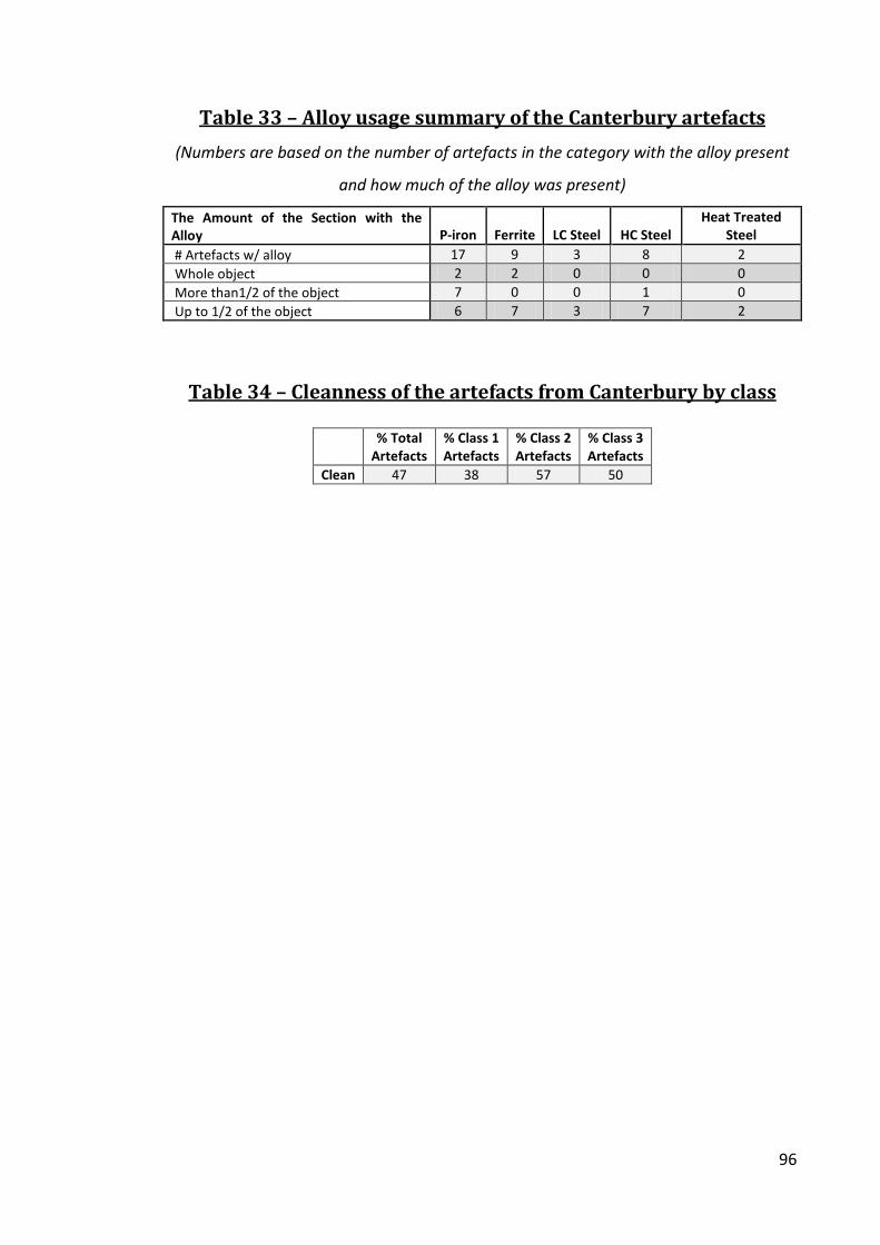
96
Table 33 – Alloy usage summary of the Canterbury artefacts
(Numbers are based on the number of artefacts in the category with the alloy present
and how much of the alloy was present)
The Amount of the Section with the Alloy P-iron Ferrite LC Steel HC Steel
Heat Treated Steel
# Artefacts w/ alloy 17 9 3 8 2 Whole object 2 2 0 0 0 More than1/2 of the object 7 0 0 1 0 Up to 1/2 of the object 6 7 3 7 2
Table 34 – Cleanness of the artefacts from Canterbury by class
% Total
Artefacts % Class 1 Artefacts
% Class 2 Artefacts
% Class 3 Artefacts
Clean 47 38 57 50

97
Table 35 – Summary of the iron artefacts from Saxon Southampton
(n/a = not applicable)
Artefact #
Description Period Site/Context
Dimensions (mm)
Weight (g)
# Sections Taken Section Placement
Class 1 168-421 Knife Middle Saxon Six Dials 13x131 n/a 1 Cross section of the blade
169-1858 Chisel Middle Saxon Six Dials 16x165 n/a 1 Cross section of the blade 169-2407 Knife Middle Saxon Six Dials 12x107 n/a 1 Cross section of the blade
169-540 Knife Middle Saxon Six Dials 14x113 n/a 1 Cross section of the blade 169-610 Knife Middle Saxon Six Dials 10x117 n/a 1 Cross section of the blade
24-22 Axe Middle Saxon Six Dials 137x45x170 n/a 1 Only one section used, a cross section of the blade 31-1137 Needle Middle Saxon Six Dials 2.5x0.1x0.1 <1 1 Longitudinal section of the needle 31-663 Knife Middle Saxon Six Dials 92x11 n/a 1 Cross section of the blade
31-92 Bill hook Middle Saxon Six Dials 65x315 n/a 2 Longitudinal section of the point and a cross section of the ball end
99-38 Knife Middle Saxon Stoner Motors St.Marys St 12x2667 n/a 1 Cross section of the blade 99-92 Knife Middle Saxon Stoner Motors St.Marys St 15x135 n/a 1 Cross section of the blade
Class 2 31-1015 Hook Middle Saxon Six Dials 5.4x0.9x0.4 7 1 Longitudinal section of the hook 31-1742 Nail Middle Saxon Six Dials 5x2x0.4 16 1 Cross section of the shank 31-1899 Nail Middle Saxon Six Dials 7.5x1.3x0.8 23 2 Cross section of the head and a cross section of the shank 31-1960 Nail Middle Saxon Six Dials 6.2x3.3x0.4 25 1 Cross section of the shank 31-402 Nail Middle Saxon Six Dials 2.5x0.7x0.7 5 1 Cross section of the shank 31-551 Nail Middle Saxon Six Dials 5.5x0.9x0.8 39 1 Cross section of the shank
Class 3 31-2110 Bar Middle Saxon Six Dials 6x1.2x0.6 16 1 Cross section 31-814 Bar Middle Saxon Six Dials 4.8x1.8x0.6 24 1 Cross section

98
Table 36 – Southampton Class 1 artefact analysis
(Hv0.2 and grain size measurements are averaged; %C is estimated)
Artefact # Description Description of Microstructure P-Iron Hv0.2
Ferrite Hv0.2
LC Steel Hv0.2
LC Steel %C
HC Steel Hv0.2
Ferrite Grain Size
(ASTM)
P-iron Grain Size
(ASTM) Clean? Heat Treated Class 1
169-421 Knife
A Type 2 with a pearlite cutting edge welded to a back that had a slightly piled looking structure that is mostly phosphoric iron with carbon at the welds between bands 146 125 146 0.1 173 3 4 Dirty No
169-1858 Chisel
A Type 3 piled structure with bands of low carbon steel, phosphoric iron and HC steel with grain boundary carbides at the tip 261 n/a 166 0.2 216 n/a 6 Clean No
169-2407 Knife
A Type 2 with a nodular carbide and ferrite tip welded to a heterogeneous phosphoric/low carbon steel back 160 n/a 152 0.1 130 n/a 2 Dirty No
169-540 Knife
A Type 2 a tempered martensite cutting edge welded to a phosphoric iron back with some carbon diffusion across the weld 155 n/a n/a n/a 601 n/a 3 Dirty Yes
169-610 Knife
A Type 2 with a tempered martensite degraded to pearlite tip welded to a heterogeneous phosphoric iron/low carbon steel back 133 n/a 149 2 381 n/a 4 Dirty Yes

99
Table 36 (cont.) – Southampton Class 1 artefact analysis
(Hv0.2 and grain size measurements are averaged; %C is estimated)
Artefact # Description Description of Microstructure
P-Iron Hv0.2
Ferrite Hv0.2
LC Steel Hv0.2
LC Steel %C
HC Steel Hv0.2
Ferrite Grain Size
(ASTM)
P-iron Grain Size
(ASTM) Clean? Heat Treated Class 1
24-22 Axe
A Type 3 piled structure with a central band of phosphoric iron welded to bands of phosphoric iron, low carbon steel, and HC steel with tempered martensite near the tip 185 n/a 193 2 237 n/a 3 Clean Yes
31-1137 Needle Ferritic iron with exterior carburization n/a 155 202 0.3 n/a 6 n/a Clean No
31-663 Knife
A Type 2 with a high phosphor us partial steel (0.1-0.7%C) tip welded to heterogeneous phosphoric iron with areas of low carbon steel back with carbon diffusion across the weld 187 n/a 171 1 180 n/a 2 Dirty No
31-92 Bill hook
A Type 3 piled structure with bands of phosphoric iron, ferrite, low carbon steel, pearlite, bainite and tempered martensite 161 131 142 0.3 472 n/a 6 Clean Yes
99-38 Knife
A Type 2 construction with a tempered martensitic tip welded to a heterogeneous phosphoric/ ferritic back with some high carbon steel along one edge and edge carbon diffusion across the weld 165 140 n/a n/a 447 4 1 Clean Yes
99-92 Knife
Mostly phosphoric iron with areas ferrite plus pearlite and carburization along the outside of the tip 163 n/a 155 0.1 253 6 3 Dirty No

100
Table 37 – Southampton Class 2 and Class 3 artefact analyses
(Hv0.2 and grain size measurements are averaged; %C is estimated)
Artefact # Description Description of Microstructure P-Iron Hv0.2
Ferrite Hv0.2
LC Steel Hv0.2
LC Steel %C
HC Steel Hv0.2
Ferrite Grain Size
(ASTM)
P-iron Grain Size
(ASTM) Clean? Heat Treated Class 2
31-1015 Hook
A slightly piled structure with heterogeneous bands of phosphoric/ferritic iron and carbon at the weld lines 136 131 126 0.2 n/a 6 3 Clean No
31-1742 Nail Heterogeneous phosphoric iron with areas of ferrite 146 106 n/a n/a n/a 6 6 Dirty No
31-1899 Nail Piled phosphoric iron with carburization of the shank 162 n/a n/a n/a 256 n/a 4 Dirty No
31-1960 Nail Heterogeneous phosphoric iron with areas of ferrite with grain boundary pearlite 188 141 126 0.1 n/a 7 7 Dirty No
31-402 Nail Phosphoric iron with slight carburization along the exterior 184 n/a n/a n/a n/a n/a 1 Clean No
31-551 Nail
Folded heterogeneous phosphoric iron carbon with carbon in the fold along with areas of grain boundary pearlite 176 n/a n/a n/a 291 n/a 4 Clean No
Class 3
31-2110 Bar
Heterogeneous phosphoric iron with areas of ferrite and a small area of low carbon steel 141 102 154 0.1 n/a 6 5 Clean No
31-814 Bar Heavily ghosted phosphoric iron with some exterior carburization 186 n/a n/a n/a 206 n/a 3 Clean No
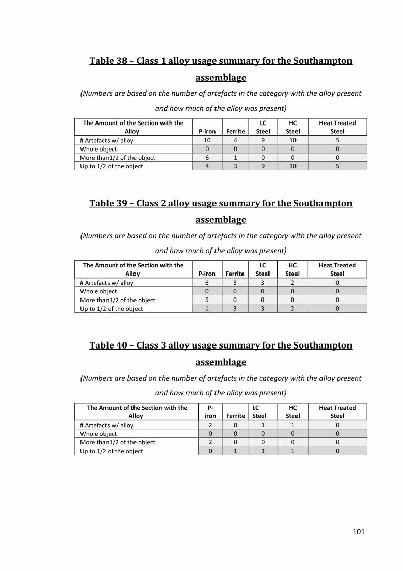
101
Table 38 – Class 1 alloy usage summary for the Southampton
assemblage
(Numbers are based on the number of artefacts in the category with the alloy present
and how much of the alloy was present)
The Amount of the Section with the Alloy P-iron Ferrite
LC Steel
HC Steel
Heat Treated Steel
# Artefacts w/ alloy 10 4 9 10 5 Whole object 0 0 0 0 0 More than1/2 of the object 6 1 0 0 0 Up to 1/2 of the object 4 3 9 10 5
Table 39 – Class 2 alloy usage summary for the Southampton
assemblage
(Numbers are based on the number of artefacts in the category with the alloy present
and how much of the alloy was present)
The Amount of the Section with the Alloy P-iron Ferrite
LC Steel
HC Steel
Heat Treated Steel
# Artefacts w/ alloy 6 3 3 2 0 Whole object 0 0 0 0 0 More than1/2 of the object 5 0 0 0 0 Up to 1/2 of the object 1 3 3 2 0
Table 40 – Class 3 alloy usage summary for the Southampton
assemblage
(Numbers are based on the number of artefacts in the category with the alloy present
and how much of the alloy was present)
The Amount of the Section with the Alloy
P-iron Ferrite
LC Steel
HC Steel
Heat Treated Steel
# Artefacts w/ alloy 2 0 1 1 0 Whole object 0 0 0 0 0 More than1/2 of the object 2 0 0 0 0 Up to 1/2 of the object 0 1 1 1 0

102
Table 41 – Phosphoric iron in Southampton
(Phosphorus content and Hardness values averaged per test site; nd = not detected; n/a = not applicable)
Artefact # Description Placement within
Artefact Ghosting Structures
# P-iron Areas
Analyzed Data Type
P-iron (ave.
wt%P) Ghosting? Etch
Resistance?
Grain Size (ave.
ASTM)
P-iron ave. Hv0.2
Class 1
168-421 Knife In the piled structure
of the knife back Inter-granular & Slag
inclusion 3
Mean 0.4 Yes Yes 4 146 Low 0.31 No Yes 4 131 High 0.48 Yes No 4 153
169-1858 Chisel Half of the piled
structure
Inter-granular & Slag inclusion; Compacted
structure 3
Mean 0.34 Yes No 6 261
Low 0.25 Yes No 6 176
169-2407 Knife
The knife back was mostly
Heterogeneous Slag inclusion 3
Mean 0.47 Yes No 2 160 Low 0.41 No No 1 143 High 0.51 Yes No 5 159
169-540 Knife The knife back EE, Slag inclusion, Inter-
granular & GB 3
Mean 0.38 Yes No 3 155 Low 0.34 Yes No 4 146 High 0.46 No No 4 162
169-610 Knife The knife back Inter-granular & EE 2
Mean 0.45 Yes No 4 133 Low 0.32 Yes No 4 126 High 0.58 Yes No 3 140
24-22 Axe A large part of the
piled structure EE, Pearlite, & Inter-granular; Ripple-like 4
Mean 0.42 Yes No 3 185 Low 0.22 Yes No 6 147 High 0.67 No No 1 210
31-1137 Needle n/a n/a nd Mean nd No No n/a n/a

103
Table 41 (cont.) – Phosphoric iron in Southampton
(Phosphorus content and Hardness values averaged per test site; nd = not detected; n/a = not applicable)
Artefact # Description Placement within
Artefact Ghosting Structures
# P-iron Areas
Analyzed Data Type
P-iron (ave.
wt%P) Ghosting? Etch
Resistance?
Grain Size (ave.
ASTM)
P-iron ave. Hv0.2
Class 1 (cont.)
31-669 Knife
Heterogeneously majority of the knife
back GB, Slag Inclusion, & EE;
Widmanstätten 5
Mean 0.55 Yes Yes 2 187 Low 0.27 No No 7 152 High 0.83 Yes No 1 224
31-92 Bill hook Bands of the piled
structure Slag Inclusion 1 Mean 0.41 Yes No 6 161
98-38 Knife
Heterogeneously majority of the knife
back Inter-granular 1 Mean 0.35 Yes Yes 1 165
99-92 Knife Most of the knife GB, Slag Inclusion, & EE 5
Mean 0.37 Yes Yes 3 163 Low 0.17 Yes No 3 156 High 0.62 No Yes 2 184
Class 2
31-1015 Hook Heterogeneously part
of the structure EE 3
Mean 0.17 Yes Yes 3 136 Low 0.16 No No 5 123 High 0.19 No No 1 148
31-1742 Nail Heterogeneously part
of the structure Inter-granular 3
Mean 0.32 Yes No 6 146 Low 0.18 No No 6 126 High 0.46 Yes No 5 168
31-1899 Nail The nail head and some
of the shank Slag inclusion, GB &
Inter-granular 4
Mean 0.49 Yes No 4 162 Low 0.25 No No 6 125 High 0.86 No No 3 199

104
Table 41 (cont.) – Phosphoric iron in Southampton
(Phosphorus content and Hardness values averaged per test site; nd = not detected; n/a = not applicable)
Artefact # Description Placement within
Artefact Ghosting Structures
# P-iron Areas
Analyzed Data Type
P-iron (ave.
wt%P) Ghosting? Etch
Resistance?
Grain Size (ave.
ASTM)
P-iron ave. Hv0.2
31-1960 Nail
Heterogeneously the majority of the
structure Inter-granular & Slag
inclusion 2
Mean 0.26 Yes No 7 188 Low 0.23 Yes No 7 186 High 0.29 Yes No 6 190
31-402 Nail The majority of the
structure Pearlitic & Inter-granular 3
Mean 0.58 Yes No 1 184 Low 0.31 No No 1 144 High 0.78 No No 2 228
31-551 Nail
Heterogeneously the majority of the
structure GB, Inter-granular & Slag inclusion; Allotriomorphs 4
Mean 0.62 Yes Yes 4 176 Low 0.35 Yes No 6 155 High 0.85 No Yes 4 206
Class 3
31-2110 Bar
Heterogeneously the majority of the
structure Inter-granular 3
Mean 0.36 Yes No 5 141 Low 0.21 Yes No 6 157 High 0.65 Yes No 4 174
31-814 Bar
Heterogeneously the majority of the
structure
GB, Pearlitic, Inter-granular & Slag inclusion; Allotriomorphs 4
Mean 0.64 Yes No 3 186 Low 0.32 Yes No 4 165 High 0.95 No No 2 224

105
Table 42 – Summary of Indicators in the Southampton assemblage
Indicator # of Artefacts P-iron Ghosting 17 P-iron Large Grains 13 P-iron Etch Resistance 6 Average Hardness (Hv0.2) 169
Table 43 – Analysis of knife SOU98-38
(Hv# - The hardness test number corresponding the image above)
Hv # Alloy Type
Vickers Hardness
(Hv) SEM
Wt%P SEM
Wt%As ASTM
Grain Size Notes HV1 Tempered Martensite 546 0.3 ± 0.1 0.0 - HV2 Fine Pearlite 348 0.1 ± 0.1 0.1 ± 0.2 - HV3 Weld-line 226 0.1 ± 0.1 3.1 ± 0.2 -
HV4 Phosphoric Iron + Pearlite 0.3%C 196 0.2 ± 0.1 0.4 ± 0.2 7
HV5 Ferrite 140 0.1 ± 0.1 0.7 ± 0.2 4 Etch Resistant
HV6 Phosphoric Iron + Pearlite 0.2%C 149 0.2 ± 0.1 0.4 ± 0.2 7
HV7 Phosphoric Iron 149 0.4 ± 0.1 0.2 ± 0.2 1 Ghosting
Table 44 – Results from McDonnell’s (1987b , 1987a) analysis of
Southampton artefacts
Total # of Artefacts % Heat Treated % with P-iron % Ghosted Knives 14 64 36 7 Other Edged tools 4 50 50 0 Total 18 67 39 6

106
Table 45 – Phosphorus in steel in the Southampton assemblage
(Phosphorus content and hardness values averaged; nd = not detected; n/a = not applicable; ns = not significant (<0.15%P))
Artefact # Description
Low Carbon Steel wt%P
Low Carbon Steel Hv0.2
Low Carbon Steel %C
Placement of Low Carbon Steel
High Carbon Steel wt%P
High Carbon Steel Hv0.2
High Carbon Steel %C
Placement of High Carbon Steel
Class 1 168-421 Knife 0.21 150 0.1 The knife back nd n/a n/a n/a
169-2407 Knife 0.27 152 0.1 Carbon diffusion just below the butt weld nd n/a n/a n/a
169-540 Knife 0.3 195 0.3 Carbon diffusion just below the butt weld nd n/a n/a n/a
169-610 Knife 0.24 149 0.2
Present in the heterogeneous knife back ns n/a n/a n/a
24-22 Axe 0.33 169 0.2 Carbon diffusion from central band ns n/a n/a n/a
31-1137 Needle 0.14 208 0.1 Carburization of the exterior nd n/a n/a n/a
31-663 Knife 0.32 171 0.1 Part of the knife tip ns n/a n/a n/a
98-38 Knife 0.18 196 0.3 Carbon diffusion just below the butt weld 0.28 546
Tempered martensite Knife tip
99-92 Knife 0.3 180 0.2 Carburization of one side of the exterior nd n/a n/a n/a
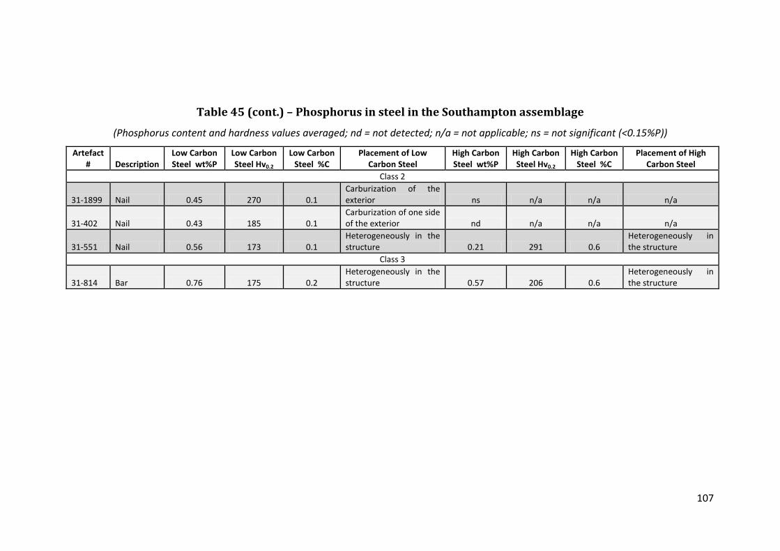
107
Table 45 (cont.) – Phosphorus in steel in the Southampton assemblage
(Phosphorus content and hardness values averaged; nd = not detected; n/a = not applicable; ns = not significant (<0.15%P))
Artefact # Description
Low Carbon Steel wt%P
Low Carbon Steel Hv0.2
Low Carbon Steel %C
Placement of Low Carbon Steel
High Carbon Steel wt%P
High Carbon Steel Hv0.2
High Carbon Steel %C
Placement of High Carbon Steel
Class 2
31-1899 Nail 0.45 270 0.1 Carburization of the exterior ns n/a n/a n/a
31-402 Nail 0.43 185 0.1 Carburization of one side of the exterior nd n/a n/a n/a
31-551 Nail 0.56 173 0.1 Heterogeneously in the structure 0.21 291 0.6
Heterogeneously in the structure
Class 3
31-814 Bar 0.76 175 0.2 Heterogeneously in the structure 0.57 206 0.6
Heterogeneously in the structure

108
Table 46 – Manufacture summary for the Southampton artefacts
# Total
Artefacts # Class 1 Artefacts
# Class 2 Artefacts
# Class 3 Artefacts
# Total Artefacts 19 11 6 2 Evidence of Cold Worked 1 1 0 0 Heat Treated 5 5 0 0 Carburized 6 3 1 2 Piled 4 2 2 0 Composite Construction 9 9 0 0 Single Alloy Construction 0 0 0 0 Heterogeneous 16 10 5 1 Clean 10 5 3 2
Table 47 – Average hardness for ferrite in Southampton classes
Class 1 Class 2 Class 3 Ave. Hv0.2 Ferrite 172 165 163
Table 48 – Alloy usage summary for class comparison for
Southampton
(Numbers are based on the number of artefacts in the category)
P-iron Ferrite LC Steel HC Steel Heat Treated Steel Class 1 10 4 9 10 5 Class 2 6 3 2 2 0 Class3 2 1 1 1 0 Total 18 8 12 13 5

109
Table 49 – Alloy usage summary of the Southampton artefacts
The Amount of the Section with the Alloy
P-iron Ferrite
LC Steel
HC Steel
Heat Treated Steel
# Artefacts w/ alloy 18 8 12 13 5 Whole object 1 0 0 0 0 More than 1/2 of the object 12 1 0 0 0 Up to 1/2 of the object 5 7 12 13 5
Table 50 – Cleanness of the artefacts from Southampton by class
% Total
Artefacts % Class 1 Artefacts
% Class 2 Artefacts
% Class 3 Artefacts
Clean 53 45 50 100
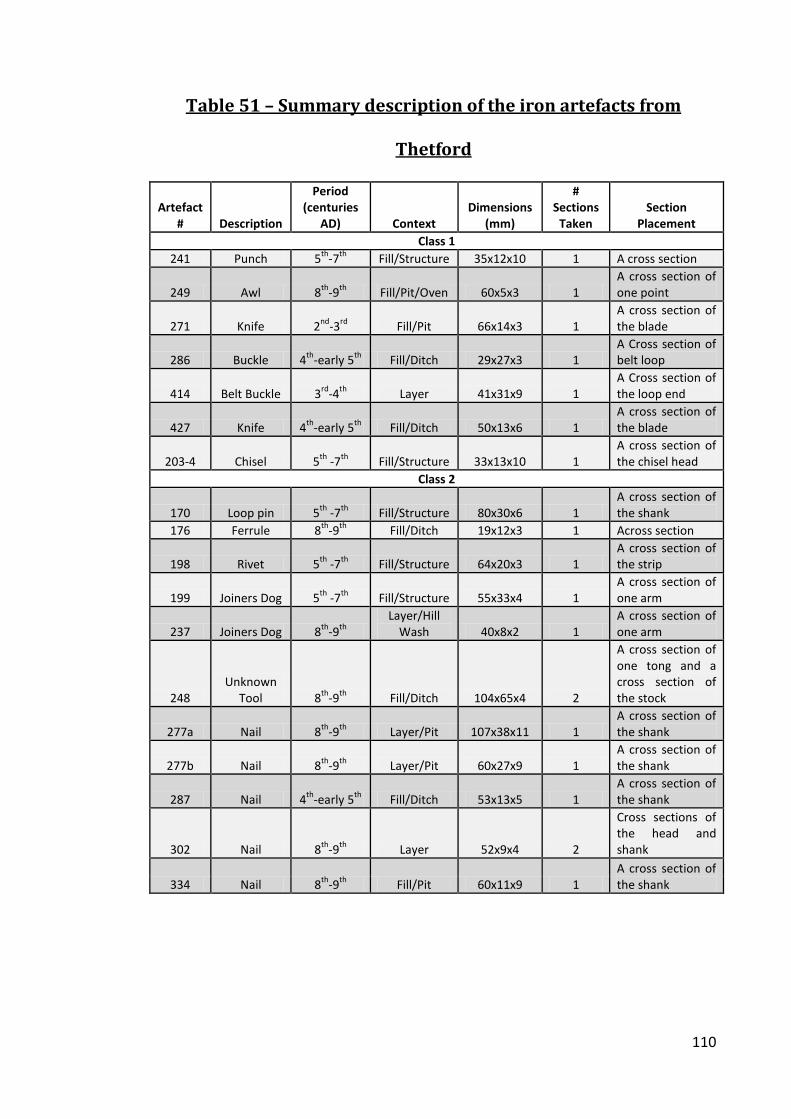
110
Table 51 – Summary description of the iron artefacts from
Thetford
Artefact # Description
Period (centuries
AD) Context Dimensions
(mm)
# Sections
Taken Section
Placement Class 1
241 Punch 5th-7th Fill/Structure 35x12x10 1 A cross section
249 Awl 8th-9th Fill/Pit/Oven 60x5x3 1 A cross section of one point
271 Knife 2nd-3rd Fill/Pit 66x14x3 1 A cross section of the blade
286 Buckle 4th-early 5th Fill/Ditch 29x27x3 1 A Cross section of belt loop
414 Belt Buckle 3rd-4th Layer 41x31x9 1 A Cross section of the loop end
427 Knife 4th-early 5th Fill/Ditch 50x13x6 1 A cross section of the blade
203-4 Chisel 5th -7th Fill/Structure 33x13x10 1 A cross section of the chisel head
Class 2
170 Loop pin 5th -7th Fill/Structure 80x30x6 1 A cross section of the shank
176 Ferrule 8th-9th Fill/Ditch 19x12x3 1 Across section
198 Rivet 5th -7th Fill/Structure 64x20x3 1 A cross section of the strip
199 Joiners Dog 5th -7th Fill/Structure 55x33x4 1 A cross section of one arm
237 Joiners Dog 8th-9th Layer/Hill
Wash 40x8x2 1 A cross section of one arm
248 Unknown
Tool 8th-9th Fill/Ditch 104x65x4 2
A cross section of one tong and a cross section of the stock
277a Nail 8th-9th Layer/Pit 107x38x11 1 A cross section of the shank
277b Nail 8th-9th Layer/Pit 60x27x9 1 A cross section of the shank
287 Nail 4th-early 5th Fill/Ditch 53x13x5 1 A cross section of the shank
302 Nail 8th-9th Layer 52x9x4 2
Cross sections of the head and shank
334 Nail 8th-9th Fill/Pit 60x11x9 1 A cross section of the shank

111
Table 51 (cont.) – Summary description of the iron artefacts from
Thetford
Artefact # Description
Period (centuries
AD) Context Dimensions
(mm)
# Sections
Taken Section
Placement Class 3
209 Bar 8th-9th Fill/Pit 37x7x5 2 Two cross sections
228 Bar 5th -7th Fill/Structure/Metal Working Evidence 44x13x9 1
A cross section
UI
210 Sheet
Fragment 8th-9th Fill/Ditch/Enclosure 25x13x3 1 A cross section
305 Strip 3rd-4th Fill/Pit 61x8x3 1 A cross section
322 Tapering
Strip 8th-9th Layer 57x12x2 1 A cross section
203-5 Chisel Set Fragment 5th -7th Fill/Structure 37x13x10 1
A cross section
Table 52 – Class 1 alloy usage summary of the Thetford
assemblage
(Numbers are based on the number of artefacts in the category with the alloy present
and how much of the alloy was present)
The Amount of the Section with the Alloy P-iron Ferrite LC Steel HC Steel Heat Treated Steel # Artefacts w/ Alloy 4 6 5 5 1 Whole Object 0 0 0 0 0 More than1/2 Object 2 1 1 1 1 Up to 1/2 Object 2 5 4 4 0

112
Table 53 – Class 1 artefact analysis from the Thetford assemblage
(Hv0.2 and grain size measurements are averaged; %C is estimate)
Artefact # Description Description of Microstructure
P-Iron Hv0.2
Ferrite Hv0.2
LC Steel Hv0.2
LC Steel %C
HC Steel Hv0.2
Ferrite Grain Size
(ASTM)
P-iron Grain Size
(ASTM) Clean? Heat
Treated Class 1
241 Punch
Heterogeneous mix containing an area of pearlite with carbon diffusing outward into a low carbon steel/ferrite n/a 99 122 3 189 7 n/a Clean No
249 Awl
A small piece of high carbon steel welded to several pieces of low carbon steel that are the result of large amounts of carbon diffusion and some carburization of the exterior n/a n/a 159 2 241 n/a n/a Clean No
271 Knife
A reverse Type 1 or Type 3 with a ghosted ferritic/phosphoric central band sandwiched between piled low carbon/bainitic steel bands 124 143 163 1 280 5 4 Clean Yes
286 Buckle A ferritic bar with significant carburization at one corner and side n/a 109 157 2 211 4 n/a Clean No
414 Buckle Mostly heterogeneous phosphoric iron with small areas to ferrite with moderate ghosting 141 160 n/a n/a n/a 5 6 Dirty No
427 Knife
A Type 2 with a phosphoric tip welded to two other heterogeneous pieces of heavily ghosted phosphoric iron with small amounts of ferrite and carbon at the weld lines 154 174 n/a n/a n/a 5 4 Dirty No
203-4 Chisel
A Type 1 or Type 3 with a central HC steel band sandwiched between piled ferritic/phosphoric bands with some carbon diffusion 121 125 160 2.0 178 6 6 Clean No

113
Table 54 – Class 2 artefact analysis from the Thetford assemblage
(Hv0.2 and grain size measurements are averaged; %C is estimated; n/a = not applicable)
Artefact # Description Description of Microstructure
P-Iron Hv0.2
Ferrite Hv0.2
LC Steel Hv0.2
LC Steel %C
HC Steel Hv0.2
Ferrite Grain Size
(ASTM)
P-iron Grain Size
(ASTM) Clean? Heat
Treated Class 2
170 Loop Pin
A banded structure with a central band of large grained ferrite sandwiched between two bands of small grained ferrite with minor grain boundary pearlite n/a 93 104 1 n/a 6 n/a Clean No
176 Ferrule
A phosphoric/ferritic ring with a low carbon steel band welded to the exterior and slight carbon diffusion 174 180 164 2 n/a 6 4 Dirty No
198 Rivet
Heterogeneous mix of phosphoric iron and ferrite with a small area of low carbon steel at one end 192 138 153 1 n/a 7 4 Dirty No
199 Joiner’s Dog Mostly low carbon steel with small areas of high carbon steel n/a n/a 193 3 176 n/a n/a Clean No
237 Joiner’s Dog Mostly ferritic with a small corner area of phosphoric iron 162 134 n/a n/a n/a 6 4 Dirty No
248 Unknown
Tool
The arm was phosphoric iron with an area of ferrite with strings of inclusions; the stock is a naturally -banded structure of HC steel and phosphoric with a corner of ferrite welded on 156 163 n/a n/a 204 6 6 Clean No

114
Table 54 (cont.) – Class 2 artefact analysis from the Thetford assemblage
(Hv0.2 and grain size measurements are averaged; %C is estimated; n/a = not applicable)
Artefact # Description Description of Microstructure
P-Iron Hv0.2
Ferrite Hv0.2
LC Steel Hv0.2
LC Steel %C
HC Steel Hv0.2
Ferrite Grain Size
(ASTM)
P-iron Grain Size
(ASTM) Clean? Heat
Treated Class 2 (cont.)
277a Nail Phosphoric iron with a little carbon in the folds 159 n/a 165 2 126 n/a 5 Dirty No
277b Nail Heterogeneous structure that is mostly phosphoric iron with areas of pearlite 161 n/a n/a n/a n/a n/a 6 Clean No
287 Nail
A heterogeneous hyper eutectic steel with ferrite along one edge and large etch resistant area in the HC steel n/a n/a 189 1 221 n/a n/a Clean No
302 Nail
A ferritic structure with some carburization along the exterior of the shank n/a 108 n/a n/a 213 6 n/a Clean No
334 Nail
A band of clean ferrite sandwiched between two bands of dirty ferrite/phosphoric iron 116 124 n/a n/a n/a 8 7 Dirty No

115
Table 55 – Class 2 alloy usage summary of the Thetford
assemblage
(Numbers are based on the number of artefacts in the category with the alloy present
and how much of the alloy was present)
The Amount of the Section with the Alloy
P-iron Ferrite
LC Steel
HC Steel
Heat Treated Steel
# Artefacts w/ Alloy 7 7 6 5 0 Whole Object 0 1 0 0 0 More than 1/2 of the Object 4 3 1 1 0 Up to 1/2 of the Object 3 3 5 4 0
Table 56 – Class 3 alloy usage summary of the Thetford
assemblage
(Numbers are based on the number of artefacts in the category with the alloy present
and how much of the alloy was present)
The Amount of the Section with the Alloy P-iron Ferrite LC Steel HC Steel Heat Treated Steel # Artefacts w/ Alloy 1 1 1 1 0 Whole Object 0 1 0 0 0 More than 1/2 of the Object 0 0 0 0 0 Up to 1/2 of the Object 1 0 1 1 0
Table 57 – UI alloy usage summary of the Thetford assemblage
(Numbers are based on the number of artefacts in the category with the alloy present
and how much of the alloy was present)
The Amount of the Section with the Alloy P-iron Ferrite LC Steel HC Steel Heat Treated Steel # Artefacts w/ Alloy 2 3 3 3 0 Whole Object 0 0 0 0 0 More than ½ of the Object 0 2 1 0 0 Up to 1/2 of the Object 2 1 2 3 0

116
Table 58 – Class 3 and UI artefact analysis for the Thetford assemblage
(Hv0.2 and grain size measurements are averaged; %C is estimated; n/a = not applicable)
Artefact # Description Description of Microstructure
P-Iron Hv0.2
Ferrite Hv0.2
LC Steel Hv0.2
LC Steel %C
HC Steel Hv0.2
Ferrite Grain Size
(ASTM)
P-iron Grain Size
(ASTM) Clean? Heat
Treated Class 3
209 Bar Completely ferritic iron n/a 101 n/a n/a n/a 4 n/a Clean No
228 Bar
Piled structure with layers of phosphoric iron, low and high carbon steel 178 n/a 131 3 138 n/a 2 Dirty No
UI
210 Sheet
Fragment A piled ferritic structure with some low carbon bands n/a 126 132 2 n/a 6 n/a Clean No
305 Strip
Heavily cold worked three ferritic bands welded together with one heavily corroded edge of HC steel; Neumann bands present n/a 205 n/a n/a 276 5 n/a Clean No
322 Tapering
Strip
An interior band phosphoric iron completely encased by LC and HC steel 171 152 148 4 205 5 6 Clean No
203-5 Chisel Set Fragment
A heterogeneous structure with areas of phosphoric iron, large areas of low carbon steel and high carbon steel in folds and carburized exterior 139 n/a 107 2 184 n/a 6 Dirty No

117
Table 59 – Phosphoric analyses iron for the Thetford assemblage
(Phosphorus content and Hardness values averaged per test site; nd = not detected; n/a = not applicable)
Artefact # Description
Placement within Artefact Ghosting Structures
# P-iron Areas
Analyzed Data Type
P-iron (ave.
wt%P) Ghosting? Etch
Resistance?
Grain Size
(ASTM)
P-iron ave. Hv0.2
Class 1 241 Punch n/a n/a nd none n/a No Yes n/a n/a 249 Awl n/a n/a nd none n/a No No n/a n/a
271 Knife Central band of a
reverse type 1 knife n/a 1 Mean 0.16 No No 4 124 286 Buckle n/a n/a nd none n/a No No n/a n/a
414 Belt Buckle Almost All
Slag inclusion, GB & Inter-granular;
Ripple-like 5
Mean 0.3 Yes Yes 6 141 Low 0.18 No Yes 4 127 High 0.45 Yes No 6 157
427 Knife Almost All GB & Inter-granular;
Widmanstätten 4
Mean 0.35 Yes No 4 154 Low 0.2 Yes No 6 150 High 0.6 No No 2 176
203-4 Chisel
Piled phosphoric/ferritic bands in a type 1 n/a 1 Mean 0.17 No Yes 6 121
Class 2 170 Loop pin n/a n/a nd none n/a No No n/a n/a
176 Ferrule The interior band EE, GB & Slag
inclusion 6
Mean 0.59 Yes Yes 4 174 Low 0.35 No No 5 160 High 1.22 No No 3 187
198 Rivet Heterogeneously
mixed in GB & Slag inclusion 4
Mean 0.61 Yes Yes 4 192 Low 0.36 Yes No 5 166 High 0.8 No Yes 2 218

118
Table 59 (cont.) – Phosphoric analyses iron for the Thetford assemblage
(Phosphorus content and Hardness values averaged per test site; nd = not detected; n/a = not applicable)
Artefact # Description
Placement within Artefact Ghosting Structures
# P-iron Areas
Analyzed Data Type
P-iron (ave.
wt%P) Ghosting? Etch
Resistance? Grain Size
(ASTM)
P-iron ave. Hv0.2
Class 2 (cont.) 199 Joiner’s Dog n/a n/a nd none n/a No No n/a n/a 237 Joiner’s Dog Small corner area Slag inclusion 1 Mean 0.29 Yes Yes 4 162
248 Unknown
Tool Most of the structure GB, EE & Slag inclusion 5
Mean 0.37 Yes Yes 6 156 Low 0.25 No No 6 131 High 0.56 Yes No 6 141
277A Nail All GB & Slag inclusion 5
Mean 0.41 Yes Yes 6 161 Low 0.3 Yes No 8 165 High 0.46 No Yes 4 166
277B Nail Heterogeneously
mixed in Inter-granular, Slag
inclusion & GB 6
Mean 0.41 Yes Yes 5 160 Low 0.18 Yes No 6 140 High 0.88 No Yes 2 213
287 Nail n/a n/a nd none n/a No No n/a n/a 302 Nail n/a n/a nd none n/a No No n/a n/a
334 Nail A corner area in the
shank n/a 1 Mean 0.35 No No 7 116 Class 3
209 Bar n/a n/a nd none n/a No No n/a n/a
228 Bar Layers mixed in the banded structure
GB &Slag inclusion; Widmanstätten 3
Mean 0.46 Yes Yes 2 178 Low 0.25 No No 5 154 High 0.63 Yes No 1 154

119
Table 59 (cont.) – Phosphoric analyses iron for the Thetford assemblage
(Phosphorus content and Hardness values averaged per test site; nd = not detected; n/a = not applicable)
Artefact # Description
Placement within Artefact Ghosting Structures
# P-iron Areas Analyzed
Data Type
P-iron (ave.
wt%P) Ghosting? Etch
Resistance? Grain Size
(ASTM)
P-iron ave. Hv0.2
UI
210 Sheet
Fragment n/a n/a nd none n/a No No n/a n/a 305 Strip n/a n/a nd none n/a No No n/a n/a
322 Tapering
Strip The interior band EE & Slag inclusion 3
Mean 0.46 Yes Yes 6 171 Low 0.35 Yes No 8 184 High 0.62 No Yes 4 169
203-5 Chisel Set
Small heterogeneous
areas Slag inclusion & Inter-
granular 5
Mean 0.36 Yes No 6 139 Low 0.25 Yes No 5 169 High 0.44 No No 5 127

120
Table 60 – Phosphorus in steel at Thetford
(Phosphorus content and hardness values averaged; nd = not detected; n/a = not applicable; ns = not significant (<0.15%P))
Artefact # Description
Low Carbon Steel wt%P
Low Carbon Steel Hv0.2
Low Carbon Steel %C
Placement of Low Carbon Steel
High Carbon Steel wt%P
High Carbon Steel Hv0.2
High Carbon
Steel %C Placement of High
Carbon Steel Class 1
271 Knife ns n/a n/a n/a 0.16, 0.21 328, 243 0.7, 0.7 The pearlite and bainite
side bands
203-4 Chisel ns n/a n/a n/a 0.18 151 0.4 Carbon diffusion in ferritic side band
Class 2
198 Rivet 0.17 153 0.1 Small area at one
end of strip nd n/a n/a n/a
248 Unknown
Tool nd n/a n/a n/a 0.41 223 0.4 Heterogeneously in the
shank of the tool
277 Nail 0.62 182 0.1 Heterogeneous area
in structure nd n/a n/a n/a Class 3
228 Bar 0.19 124 0.1 A corner of the bar
section ns n/a n/a n/a UI
322 Tapering Strip 0.23 176 0.3 The exterior band nd n/a n/a n/a
203-5 Chisel Set Fragment nd n/a n/a n/a 0.15 120 0.5 In a carbon rich fold

121
Table 61 – Phosphoric iron indicators in the Thetford assemblage
# of Artefacts P-iron Ghosting 11 P-iron Large Grains 5 P-iron Etch Resistance 10 Average Hv0.2 153
Table 62 – Manufacture summary for the Thetford artefacts
# Total
Artefacts # Class 1 Artefacts
# Class 2 Artefacts
# Class 3 Artefacts UI
# Total Artefacts 23 7 10 2 4
Evidence of Cold Working 2 0 1 0 1
Heat Treated 1 1 0 0 0
Carburized 5 3 1 0 1
Piled 4 2 0 1 1
Composite Construction 6 4 1 0 1
Single Alloy Construction 1 0 0 1 0
Heterogeneous 14 4 8 0 2
Clean 16 5 6 1 3
Table 63 – Average hardness for ferrite in the Thetford classes
Class 1 Class 2 Class 3 UI Ave. Hv0.2 Ferrite 135 134 101 161
Table 64 – Thetford alloy usage based on class
(Numbers are based on the number of artefacts in the category)
Total # Artefacts P-iron Ferrite LC Steel HC Steel Heat Treated Steel Class 1 8 4 6 5 5 1 Class 2 11 7 7 7 4 0 Class 3 2 1 1 1 1 0 UI 4 2 3 3 3 0 Total 24 14 17 16 14 1

122
Table 65 – Alloy usage summary for the Thetford assemblage
The Amount of the Section with the Alloy P-iron Ferrite
LC Steel
HC Steel
Heat Treated Steel
# Artefacts w/ Alloy 14 17 16 14 1 Whole Section 0 2 0 0 0 More than 1/2 of the Section 6 6 3 2 1 Up to 1/2 of the Section 8 9 13 12 0
Table 66 – Cleanness of the artefacts from Thetford by class
# Total
Artefacts % Class 1 Artefacts
% Class 2 Artefacts
% Class 3 Artefacts
% UI Artefacts
Clean 70 71 60 50 75

123
Table 67 – Summary of the iron artefacts from Wharram Percy
(n/a = not applicable)
Artefact # Description
Period (centuries AD) Context
Dimensions (mm)
Weight (g)
# Sections Taken Section Placement
Class1 134 Knife 7th-8th 44/139 65x14 n/a 1 Cross section of blade
159 Knife 7th-8th 85/29/4 Surface in a domestic zone 72x12 n/a 2
Cross-sections of cutting edge and back
176 Knife 7th-8th 85/29/6 Surface in a domestic zone 73x11 n/a 2
Cross-sections of cutting edge and back
237 Knife 7th-8th 85/104 144x15 n/a 1 Cross section of blade
307 Knife 7th-8th 85/148 73x12 n/a 2 Cross-sections of cutting edge and back
308 Knife 7th-8th 85/104/6 62x13 n/a 1 Cross section of blade
442 Knife 7th-8th 59/40/8 Surface in a domestic zone 67x14 n/a 2
Cross-sections of cutting edge and back
472 Knife 7th-8th 59/127/22 Smithy ditch fill 90x14 n/a 2 Cross-sections of cutting edge and back
Class 2
160 Nail 7th-8th 85/29/11 Surface in a domestic zone 35x13x12 5 2 Cross sections of head and shank
218 Nail 7th-8th 85/72/17 27x15x10 4 Cross sections of head and tip 219 Nail 7th-8th 81/17/14 63x12x6 12 1 Cross section of upper shank 387 Nail 7th-8th 76/50/5 39x18x14 8 1 Cross section of head 394 Nail 7th-8th 76/68/24 36x11x16 6 2 Cross sections of head and shank 398 Nail 7th-8th 44/117 33x11x4 3 1 Cross section of head 430 Nail 7th-8th 59/74/16 82x6x4 5 1 Cross section of upper shank 532 Nail 7th-8th 81/119/3 22x8x6 4 1 Cross section of lower shank 550 Nail 7th-8th 76/28/3 29x11x4 3 1 Cross section of upper shank 556 Nail 7th-8th 76/68/24 20x19x13 3 1 Cross section of upper shank

124
Table 67 (cont.) – Summary of the iron artefacts from Wharram Percy
(n/a = not applicable)
Artefact # Description Period (centuries AD) Context Dimensions (mm) Weight (g) # Sections Taken Section Placement Class 3
95 Bar 7th-8th 44/1 72x5x5 n/a 1 Cross section 115 Bar 7th-8th 44/9 51x1x0.9 n/a 1 Cross section 120 Bar 7th-8th 44/30 28x6x1 n/a 1 Cross section 260 Bar/Strip 7th-8th 81/109/19 49x5x3 n/a 1 Cross section 299 Bar/Strip 7th-8th 59/19/22 89x6x3 n/a 1 Cross section 320 Bar 7th-8th 59/10/21 158x2x1 n/a 1 Cross section 364 Bar 7th-8th 59/127/22 94x6x4 n/a 1 Cross section 369 Bar 7th-8th 81/111/19 80x4x4 n/a 1 Cross section 547 Bar 7th-8th 76/16/7 62x9x3 n/a 1 Cross section

125
Table 68 – Class 1 artefact analysis for Wharram Percy
(Hv0.2 and grain size measurements are averaged; %C is estimated; n/a = not applicable)
Artefact # Description Description of Microstructure
P-Iron Hv0.2
Ferrite Hv0.2
LC Steel Hv0.2
LC Steel %C
HC Steel Hv0.2
P-iron Grain Size
(ASTM)
Ferrite Grain Size
(ASTM) Clean? Heat
Treated Class 1
134 Knife A Type 3 with bands of phosphoric iron and low carbon steel 183 n/a n/a n/a n/a 5 n/a Clean No
159 Knife
A Type 2 with a tempered martensite tip containing several scarf welds and a phosphoric iron back also banded with scarf weld 161 n/a n/a n/a 473 4 n/a Clean Yes
176 Knife
A Type 2 low carbon steel worn cutting edge with a phosphoric iron heavily ghosted back 177 106 n/a n/a n/a 2 6 Clean No
237 Knife A Type 2 with a high carbon tip and a piled ferritic back n/a 100 n/a n/a 152 n/a 5 Clean No
307 Knife
A Type 0/2 heterogeneous knife with mostly phosphoric and ferritic iron and small areas of low carbon steel 159 154 n/a n/a n/a 6 8 Clean No
308 Knife
A Type 2 heavily worn high carbon steel tip and with slight carbon diffusion into a ferritic back n/a 181 208 0.3 225 n/a 3 Clean No
442 Knife
A Type 1/3 with a thin central 0.4%C steel band and bands of piled phosphoric iron on either side 142 n/a 182 0.3 n/a 3 n/a Dirty No
472 Knife A Type 2 with a high carbon tip welded to a phosphoric iron back 185 n/a 137 0.3 323 4 n/a Dirty No

126
Table 69 – Class 2 artefact analysis for Wharram Percy
(Hv0.2 and grain size measurements are averaged; %C is estimated; n/a = not applicable)
Artefact # Description Description of Microstructure
P-Iron Hv0.2
Ferrite Hv0.2
LC Steel Hv0.2
LC Steel %C
HC Steel Hv0.2
P-iron Grain Size (ASTM)
Ferrite Grain Size (ASTM) Clean?
Heat Treated
Class 2
160 Nail Completely phosphoric iron and heavily ghosted 202 n/a n/a n/a n/a 3 n/a Clean No
218 Nail Completely phosphoric iron and heavily ghosted 224 n/a n/a n/a n/a 5 n/a Clean No
219 Nail
Phosphoric iron with a small area of ferrite and a greater concentration of inclusions 168 86 n/a n/a n/a 1 6 Dirty No
287 Nail Completely ferritic iron n/a 141 n/a n/a n/a n/a 7 Dirty No
394 Nail A heterogeneous structure with areas of phosphoric iron and pearlite 155 n/a 125 0.3 141 3 n/a Clean No
398 Nail A heterogeneous structure of low carbon steel with areas of ferrite n/a 130 157 0.2 n/a n/a 7 Clean No
430 Nail Ferrite with a small area with grain boundary pearlite n/a 115 134 0.1 n/a n/a 7 Clean No
532 Nail A completely ferritic iron n/a 97 n/a n/a n/a n/a 5 Clean No
550 Nail A heterogeneous structure mostly phosphoric iron with areas of pearlite 177 n/a 134 0.2 175 n/a n/a Dirty No
556 Nail
Completely phosphoric iron and heavily ghosted with slight carburization along one edge of the shank 177 n/a n/a n/a n/a 4 n/a Dirty No

127
Table 70 – Class 3 artefact analysis for Wharram Percy
(Hv0.2 and grain size measurements are averaged; %C is estimated; n/a = not applicable)
Artefact # Description Description of Microstructure
P-Iron Hv0.2
Ferrite Hv0.2
LC Steel Hv0.2
LC Steel %C
HC Steel Hv0.2
P-iron Grain Size
(ASTM)
Ferrite Grain Size
(ASTM) Clean? Heat
Treated Class 3
95 Bar Completely phosphoric iron and heavily ghosted 166 n/a n/a n/a n/a 3 n/a Clean No
115 Bar Mostly phosphoric iron with a small carburized corner of low carbon steel 131 n/a n/a n/a n/a 2 n/a Dirty No
120 Bar
A central band of ferrite/low carbon steel sandwiched between bands of phosphoric iron 177 158 209 0.2 n/a 5 8 Dirty No
260 Bar A heterogeneous structure of phosphoric iron, ferrite and low carbon steel 140 127 104 0.1 n/a 5 6 Dirty No
299 Bar Mostly ferritic with carburization along 2 edges n/a 118 157 0.1 207 n/a 5 Dirty No
320 Bar Completely phosphoric iron and heavily ghosted 205 n/a n/a n/a n/a 6 n/a Dirty No
364 Bar A heterogeneous structure of ferrite/low carbon steel n/a 90 130 0.2 n/a n/a 6 Clean No
369 Bar
A small area of high carbon steel diffusing into the almost homogenous low-carbon steel that comprises the rest of the section n/a n/a n/a n/a 273 n/a n/a Clean No
547 Bar
A naturally banded mostly phosphoric/ferritic structure with carbon at the weld lines 145 127 125 0.1 n/a 6 7 Dirty No

128
Table 71 – Class 1 alloy usage for the Wharram Percy assemblage
(Numbers are based on the number of artefacts with that particular amount of the
alloy present)
Composition of Artefact P-iron Ferrite LC Steel HC Steel Heat Treated Steel # Artefacts w/ Alloy 6 4 3 4 1 Whole Object 0 0 0 0 0 More than 1/2 of the Object 4 2 0 0 0 Up to 1/2 of the Object 2 2 3 4 1
Table 72 – Class 2 alloy usage for the Wharram Percy assemblage
(Numbers are based on the number of artefacts with that particular amount of the
alloy present)
Composition of Artefact P-iron Ferrite LC Steel HC Steel Heat Treated Steel # Artefacts w/ Alloy 6 5 4 2 0 Whole Object 2 2 0 0 0 More than ½ of the Object 3 1 1 0 0 Up to 1/2 of the Object 1 2 3 2 0
Table 73 – Class 3 alloy usage for the Wharram Percy assemblage
(Numbers are based on the number of artefacts with that particular amount of the
alloy present)
Composition of Artefact P-iron Ferrite LC Steel HC Steel Heat Treated Steel # Artefacts w/ Alloy 6 5 7 2 0 Whole Object 2 0 0 0 0 More than ½ of the Object 2 2 2 0 0 Up to 1/2 of the Object 2 3 5 2 0

129
Table 74 – Phosphoric iron analyses from the Wharram Percy assemblage
(Phosphorus content and hardness values averaged per test site; nd = not detected; n/a = not applicable)
Artefact # Description Placement within Artefact Ghosting Structures
# P-iron Areas
Analyzed Data Type
P-iron (ave.
wt%P) Ghosting? Etch
Resistance? Grain Size
(ASTM)
P-iron ave. Hv0.2
Class 1
134 Knife The main component, but
with carburized areas n/a 2
Mean 0.43 No No 5 183 Low 0.3 No No 6 165 High 0.57 No No 3 202
159 Knife Part of the knife back GB & Ghosted
grains; Needle like 5
Mean 0.34 Yes No 4 161 Low 0.2 Yes No 6 143 High 0.67 No No 2 181
176 Knife All but cutting edge
Inter-granular, Slag inclusion & Edge
Effects 4
Mean 0.56 Yes Yes 2 177 Low 0.37 Yes Yes 2 159 High 0.72 No No 1 184
237 Knife nd n/a nd Mean nd No No n/a n/a
307 Knife Heterogeneously in the
structure
Slag inclusions & Inter-granular;
Ripple-like 4
Mean 0.3 Yes No 6 159 Low 0.17 No No 7 124 High 0.45 Yes No 4 184
308 Knife nd n/a nd Mean nd No No n/a n/a
442 Knife Piled on either side of a central HC steel band n/a 3
Mean 0.26 No No 3 142 Low 0.18 No No 2 135 High 0.3 No No 3 147
472 Knife The knife back
Inter-granular, Slag inclusion & Edge
effects 5
Mean 0.55 Yes No 4 185 Low 0.35 No No 5 166 High 0.74 Yes No 2 192

130
Table 74 (cont.) – Phosphoric iron analyses from the Wharram Percy assemblage
(Phosphorus content and hardness values averaged per test site; nd = not detected; n/a = not applicable)
Artefact # Description
Placement within Artefact Ghosting Structures
# P-iron Areas
Analyzed Data Type
P-iron (ave.
wt%P) Ghosting? Etch
Resistance? Grain Size
(ASTM)
P-iron ave. Hv0.2
Class 2
160 Nail All GB, Slag inclusion, & Inter-
granular, Needle-like 7
Mean 0.65 Yes Yes 3 202 Low 0.53 Yes No 4 169 High 0.82 No No 1 209
218 Nail All
Inter-granular & Slag inclusion; Widmanstätten
like 7
Mean 0.27 Yes Yes 5 224 Low 0.23 Yes Yes 3 219 High 0.31 Yes No 7 151
219 Nail All Slag inclusions & Inter-
granular; Ripple-like 5
Mean 0.65 Yes No 1 168 Low 0.41 Yes No 1 141 High 0.83 No No 1 187
287 Nail nd n/a nd Mean nd No Yes n/a n/a
394 Nail Heterogeneously in the
structure Inter-granular & Pearlite;
Ripple-like 6
Mean 0.4 Yes Yes 3 155 Low 0.2 No No 5 120 High 0.57 No No 1 186
398 Nail nd n/a nd Mean nd No No n/a n/a 430 Nail nd n/a nd Mean nd No No n/a n/a 532 Nail nd n/a nd Mean nd No No n/a n/a
550 Nail
Heterogeneously a large part of the
structure Slag inclusion & Inter-granular; Ripple-like 5
Mean 0.5 Yes No n/a 177 Low 0.15 Yes No n/a 133 High 0.84 Yes No n/a 196
556 Nail All
Inter-granular & Slag inclusion; Needle & Widmanstätten-like 8
Mean 0.49 Yes No 4 177 Low 0.45 No No 1 163 High 0.55 Yes No nd 196

131
Table 74 (cont.) – Phosphoric iron analyses from the Wharram Percy assemblage
(Phosphorus content and hardness values averaged per test site; nd = not detected; n/a = not applicable)
Artefact # Description Placement within Artefact Ghosting Structures
# P-iron Areas
Analyzed Data Type
P-iron (ave.
wt%P) Ghosting? Etch
Resistance? Grain Size
(ASTM)
P-iron ave. Hv0.2
Class 3
95 Bar All GB & Inter-granular;
Ripple-like 6
Mean 0.4 Yes Yes 3 166 Low 0.26 Yes No 2 160 High 0.61 No No 1 211
115 Bar All
Slag-inclusion & inter-granular;
Ripple-like 3
Mean 0.4 Yes No 2 131 Low 0.37 Yes No 4 129 High 0.42 No No 1 131
120 Bar 3/4s of the structure;
Possibly heterogeneously Slag-inclusion & GB 6
Mean 0.52 Yes Yes 5 177 Low 0.3 Yes No 6 177 High 0.81 No Yes 5 176
260 Bar Heterogeneously in the
structure Inter-granular;
Ripple-like 2
Mean 0.22 Yes No 5 140 Low 0.17 No No 6 130 High 0.26 Yes No 3 149
299 Bar nd n/a nd Mean nd No No n/a n/a
320 Bar All Slag inclusion & Inter-granular 3
Mean 0.65 Yes Yes 6 205 Low 0.54 Yes No 6 182 High 0.8 No Yes 7 224
354 Bar nd n/a nd Mean nd No No n/a n/a 369 Bar nd n/a nd Mean nd No No n/a n/a
547 Bar In heterogeneous bands
that comprise the structure n/a 2
Mean 0.25 No Yes 6 145 Low 0.21 No No 6 136 High 0.29 No No 6 154

132
Table 75 – Phosphorus in steel in the Wharram Percy assemblage
(Phosphorus content and hardness values averaged; nd = not detected; n/a = not applicable)
Artefact # Description
Low Carbon Steel wt%P
Low Carbon Steel Hv0.2
Low Carbon Steel %C
Placement of Low Carbon Steel
High Carbon Steel wt%P
High Carbon Steel Hv0.2
High Carbon Steel %C
Placement of High Carbon Steel
Class 1 134 Knife 0.62 208 0.3 Knife back nd n/a n/a n/a
159 Knife nd n/a n/a n/a 0.21 370 Tempered Martensite Knife tip
308 Knife 0.23 180 0.2 Carbon diffusion on back
next to weld line nd n/a n/a n/a Class 2
398 Nail 0.16 184 0.2 Top of nail head nd n/a n/a n/a
550 Nail 0.29 152 0.1 Centre of heterogeneous
structure 0.2 175 0.4
Centre of heterogeneous
structure
556 Nail nd n/a n/a n/a 0.48 208 0.4 Carburized side of
shank Class 3
115 Bar 0.56, 0.42 151, 157 0.1 Corner of the bar nd n/a n/a n/a
260 Bar 0.16 113 0.2 Heterogeneously in the
structure nd n/a n/a n/a
369 Bar 0.41, 0.20 195, 184 0.2, 0.3 Centre of bar section 0.22, 0.32 266, 283 0.6 On outer edge of cross
section 547 Bar 0.24 143 0.2 Edge of bar section nd n/a n/a n/a

133
Table 76 – Phosphoric iron indicators in the Wharram Percy
assemblage
# of Artefacts P-iron Ghosting 15 P-iron Large Grains 13
P-iron Etch Resistance 9 Average Hv0.2 171
Table 77 – Analysis of nail WP218
(Hv # - The hardness test number corresponding to the image above)
Hv # Alloy Type
Vickers Hardness
(Hv0.2) SEM
Wt%P SEM
Wt%As ASTM Grain
Size Notes Hv1 Phosphoric Iron 151 0.3 ± 0.1 0.4 ± 0.2 7 Ghosting Hv2 Phosphoric Iron 155 0.2 ± 0.1 0.6 ± 0.2 4 Etch Resistant Hv3 Phosphoric Iron 230 0.3 ± 0.1 0.4 ± 0.2 5 Ghosting + Etch Resistant Hv4 Phosphoric Iron 219 0.2 ± 0.1 0.3 ± 0.2 3 Ghosting + Etch Resistant Hv5 Phosphoric Iron 258 0.3 ± 0.1 0.8 ± 0.2 5 elongated Ghosting + Etch Resistant Hv6 Phosphoric Iron 292 0.2 ± 0.1 0.6 ± 0.2 6 elongated Ghosting + Etch Resistant Hv7 Phosphoric Iron 262 0.2 ± 0.1 0.6 ± 0.2 6
Table 78 – Manufacture summary for the Wharram Percy
artefacts
# Total
Artefacts
# Class 1
Artefacts
# Class 2
Artefacts
# Class 3
Artefacts # Total Artefacts 27 8 10 9 Evidence of Cold Working 2 0 2 0 Heat Treated 1 1 0 0 Carburized 5 1 2 2 Piled 2 2 0 0 Composite Construction 7 7 0 0 Single Alloy Construction 6 0 4 2 Heterogeneous 11 2 4 5 Clean 17 6 7 4

134
Table 79 – Average hardness for ferrite in the Wharram Percy
classes
Class 1 Class 2 Class 3
Ave. Hv0.2 Ferrite 168 184 161
Table 80 – Wharram Percy alloy usage based on class
(Numbers are based on the number of artefacts in the category)
Class Total # Artefacts P-iron Ferrite LC Steel HC Steel Heat Treated Steel Class 1 8 6 4 3 4 1 Class 2 10 6 5 4 2 0 Class 3 9 6 5 7 2 0 Total 27 18 14 14 8 1
Table 81 –Alloy usage summary for the Wharram Percy
assemblage
(Numbers are based on the number of artefacts in the category with the alloy present
and how much of the alloy was present)
Composition of Artefact P-iron Ferrite LC Steel HC Steel Heat Treated Steel # Artefacts w/ Alloy 18 14 14 8 1 Whole Object 4 2 0 0 0 More than ½ of the Object 9 5 3 0 0 Up to ½ of the Object 5 7 11 8 1

135
Table 82 – Cleanness of the artefacts from Wharram Percy by
class
# Total Artefacts
% Class 1 Artefacts
% Class 2 Artefacts
% Class 3 Artefacts
Clean 27 75 70 44
Table 83 – Summary of the iron artefacts from Winchester
(Measurements and dates from Rulton (2003))
Artefact #
Artefact Type
Period (centuries AD) Class Context
Dimensions (mm)
# Sections Placement
NR 8 Knife 9th-11th 1 Pit 146 x 18 2 The back and cutting
edge
SXS 93 Knife 9th-11th 1 Pit 108 x 16 2 The back and cutting
edge
BRI 4154 Knife 9th-11th 1 n/a 144 x 16 1 A complete cross-
section
VR 8580 Knife 11th–12th 1 Pit 202 x 20 1 A small piece of the
back section
Table 84 – Manufacture summary for the Winchester artefacts
# Total
Artefacts # Total Artefacts 4 Evidence of Cold Working 1 Heat Treated 1 Carburized 0 Piled 0 Composite Construction 3 Single Alloy Construction 0 Heterogeneous 2 Clean 3
Table 85 – Class 1 alloy usage for the Winchester assemblage
(Numbers are based on the number of artefacts in the category with the alloy present
and how much of the alloy was present)
The Amount of the Section with the Alloy P-iron Ferrite
LC Steel
HC Steel
Heat Treated Steel
# Artefacts w/ Alloy 3 2 3 4 1 Whole Object 0 0 0 0 0 More than1/2 Object 0 1 0 0 0 Up to 1/2 Object 3 1 3 4 1

136
Table 86 – Phosphoric iron in the Winchester assemblage
(n/a =not applicable; nd = not detected)
Artefact #
Artefact Type
Placement within
Artefact Ghosting
Structures
# P-iron Areas
Analyzed Data Type
P-iron (ave.
wt%P) Ghosting
?
Etch Resistance
?
Grain Size (ave.
ASTM)
P-iron ave. Hv0.2
NR 8 Knife nd nd nd Mean nd No No 3 n/a
SXS 93 Knife
Bands either side of Central steel band
Slag inclusion and intra granular 6
Mean 0.39 Yes Yes 4 166 Low 0.18 Yes No 1 150
High 0.50 No Yes 3 171
BRI 4154 Knife
Alternating bands
Slag inclusion,
intra granular, and grain boundary 5
Mean 0.41 Yes No 6 169 Low 0.31 Yes No 5 190
High 0.48 No No 5 154
VR 8580 Knife
The edge of one band n/a 1 Mean 0.19 No No 7 123

137
Table 87 –Class 1 artefact analysis for the Winchester assemblage
(Hv0.2 and grain size measurements are averaged; %C is estimated; n/a = not applicable)
Artefact # Artefact Type Description of Microstructure
P-Iron Hv0.2
Ferrite Hv0.2
LC Steel Hv0.2
LC Steel %C
HC Steel Hv0.2
P-iron Grain Size
(ASTM)
Ferrite Grain Size
(ASTM) Clean? Heat
Treated
NR 8 Knife
Type 2 knife with a large grained ferritic back welded to martensite cutting edge with carbon diffusion across
the weld-line. Also Neumann bands can be seen in the knife back. n/a 130 187 0.1 520 3 3 Clean Yes
SXS 93 Knife Type 1 knife with pearlite sandwiched between bands
of ferrite and phosphoric iron 166 204 112 0.1 395 4 3 Dirty No
BRI 4154 Knife Pattern welded with a series of transverse phosphoric
iron and HC steel bands with a HC steel tip 169 n/a n/a n/a 329 6 n/a Clean No
VR 8580 Knife Heavily corroded only back survived consisting of bands
of ferrite and pearlite 123 n/a 165 0.3 372 7 n/a Clean No

138
Table 88 – Phosphorus in the steel from the Winchester
assemblage
(Measurements are from individual test sites with estimated carbon content)
Artefact # Description
High Carbon Steel wt%P
High Carbon Steel Hv0.2
High Carbon Steel %C Placement
NR 8 Knife 0.16 244 0.5 In carbon diffusion near
weld line VR 8580 Knife 0.29 215 0.6 At edge of steel band

139
Table 89 – Summary of the iron artefacts from Worcester
Artefact # Description Period (centuries
AD) Context Dimensions
(mm) Weight
(g) # Sections
Taken Section Placement Class 1
(16692) 5657 Hook Tag 9th-11th Soil accumulation; Pasture 28x17x2 2 1 Cross section of hook
(17274) 6302 Key Bit 9th-11th Ground surface 20x28x9 84 1 Cross section of the key
(17300) 6411 Padlock 9th-11th
Dump; Intrusive in earlier period 87x25x24 73 1 Sliver taken from outer casing
16758 Pick Head 9th-11th Secondary fill of pit 129x20x15 101 2 Cross section of head and longitudinal of one point
17106 Knife 9th-11th Secondary rubbish fill of pit 96x14x4 8 1 Cross section of blade (17304)
6489 Knife Tang 9th-11th Arbitrary layer; Intrusive fill in
early period 87x11x2 4 1 Cross section of knife tang Class 2
(16692) 5609 Nail 9th-11th
Arbitrary layer; Intrusive fill in early period 19x3x2 1 1 Cross section of shank
(16692) 5620 Nail 9th-11th
Arbitrary layer; Intrusive fill in early period unknown 20 1 Cross sections of head and shank
(16692) 5646 Nail 9th-11th
Arbitrary layer; Intrusive fill in early period 65x9x7 11 1 Cross section of the shank
(17289) 6319 Nail 9th-11th
Arbitrary layer; Intrusive fill in early period 45x3x2 4 1 Cross section of the shank
(17300) 6477 Nail 9th-11th
Dump; Intrusive in earlier period 25x4x3 1 1 Cross section of the shank
Class 3 (17289)
6317 Strip
Fragment 9th-11th Trampled soil accumulation 47x8x4 6 1 Cross section

140
Table 90 – Class 1 artefact analysis for the Worcester assemblage
(Hv0.2 and grain size measurements are averaged; %C is estimated; n/a = not applicable)
Artefact # Description Description of Microstructure
P-Iron Hv0.2
Ferrite Hv0.2
LC Steel Hv0.2
LC Steel %C
HC Steel Hv0.2
Ferrite Grain Size
(ASTM)
P-iron Grain Size
(ASTM) Clean? Heat
Treated Class 1
(16692) 5657 Hook Tag
A natural slightly banded structure with phosphoric large grain bands and ferritic
smaller grain bands 178 106 n/a n/a n/a 6 5 Clean No (17274)
6302 Padlock
Key Entirely composed of low carbon steel n/a n/a 205 0.2 n/a 8 n/a Clean No (17300)
6411 Padlock Completely ferritic iron n/a 131 n/a n/a n/a 4 n/a Clean No
16758 Pick Head
A type 5 Several pieces of high/medium carbon steel welded together with a
martensitic tip n/a n/a n/a n/a 414 n/a n/a Clean Yes
17106 Knife
A type 2 with an medium/high carbon steel tip scarf welded a high carbon steel
piece butt welded to a ferritic back n/a 91 145 0.3 165 5 n/a Clean No
(17304) 6489 Knife Tang
A possible type 2 knife tang with a ferritic band welded to a high carbon steel
diffusing into low carbon steel n/a 183 175 0.1 244 6 n/a Dirty No
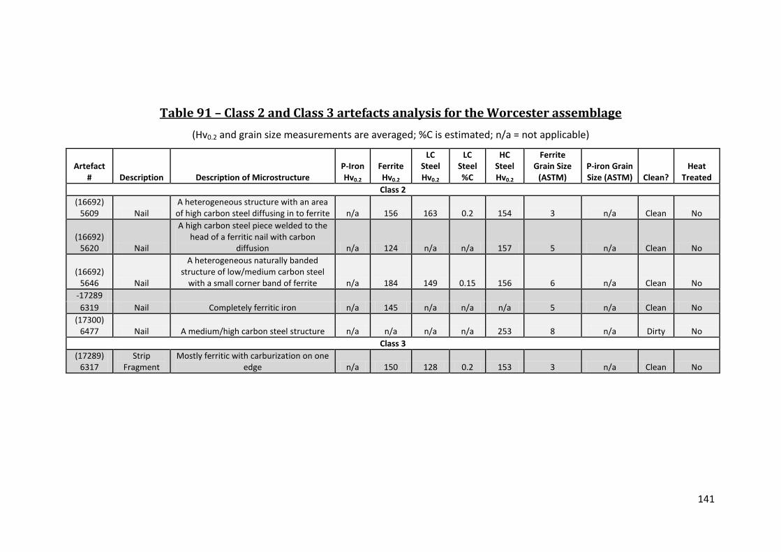
141
Table 91 – Class 2 and Class 3 artefacts analysis for the Worcester assemblage
(Hv0.2 and grain size measurements are averaged; %C is estimated; n/a = not applicable)
Artefact # Description Description of Microstructure
P-Iron Hv0.2
Ferrite Hv0.2
LC Steel Hv0.2
LC Steel %C
HC Steel Hv0.2
Ferrite Grain Size
(ASTM) P-iron Grain Size (ASTM) Clean?
Heat Treated
Class 2 (16692)
5609 Nail A heterogeneous structure with an area of high carbon steel diffusing in to ferrite n/a 156 163 0.2 154 3 n/a Clean No
(16692) 5620 Nail
A high carbon steel piece welded to the head of a ferritic nail with carbon
diffusion n/a 124 n/a n/a 157 5 n/a Clean No
(16692) 5646 Nail
A heterogeneous naturally banded structure of low/medium carbon steel
with a small corner band of ferrite n/a 184 149 0.15 156 6 n/a Clean No -17289
Nail Completely ferritic iron n/a 145 n/a n/a n/a 5 n/a Clean No 6319 (17300)
6477 Nail A medium/high carbon steel structure n/a n/a n/a n/a 253 8 n/a Dirty No Class 3
(17289) 6317
Strip Fragment
Mostly ferritic with carburization on one edge n/a 150 128 0.2 153 3 n/a Clean No

142
Table 92 – Class 1 alloy usage in the Worcester assemblage
(Numbers are based on the number of artefacts with that particular amount of the
alloy present)
The Amount of the Section with the Alloy P-iron Ferrite
LC Steel
HC Steel
Heat Treated Steel
# Artefacts w/ Alloy 1 4 3 3 1 Whole Section 0 1 1 1 0 More than 1/2 of the Section 0 0 0 1 0 Up to 1/2 of the Section 1 3 2 1 1
Table 93 – Class 2 alloy usage in the Worcester assemblage
(Numbers are based on the number of artefacts with that particular amount of the
alloy present)
The Amount of the Section with the Alloy P-iron Ferrite
LC Steel
HC Steel
Heat Treated Steel
# Artefacts w/ Alloy 0 4 2 4 0 Whole Section 0 1 0 1 0 More than 1/2 of the Section 0 1 1 0 0 Up to 1/2 of the Section 0 2 1 3 0
Table 94 – Class 3 alloy usage in the Worcester assemblage
(Numbers are based on the number of artefacts with that particular amount of the
alloy present)
The Amount of the Section with the Alloy P-iron Ferrite LC Steel HC Steel Heat Treated Steel # Artefacts w/ Alloy 0 1 1 1 0 Whole Section 0 0 0 0 0 More than 1/2 of the Section 0 1 0 0 0 Up to 1/2 of the Section 0 0 1 1 0

143
Table 95 – Phosphoric iron analyses from Worcester
(Phosphorus content and hardness values averaged per test site; nd = not detected; n/a = not applicable)
Artefact # Description Phosphoric iron placement Ghosting Structures
# P-iron Areas Analyzed
Data Type
P-iron (ave. wt%P) Ghosting?
Etch Resistance?
Grain Size (ave. ASTM)
P-iron ave. Hv0.2
5657 Hook Tag Large grain bands in a slightly piled
structure Inter-granular 4
Mean 0.3 Yes Yes 5 178 Low 0.18 No No 5 131 High 0.49 No Yes 5 241

144
Table 96 – Manufacture of the Worcester artefacts
# Total
Artefacts # Class 1 Artefacts
# Class 2 Artefacts
# Class 3 Artefacts
# Total Artefacts 12 6 5 1 Evidence of Cold Working 0 0 0 0 Heat Treated 1 1 0 0 Carburized 1 0 0 1 Piled 0 0 0 0 Composite Construction 4 3 1 0 Single Alloy Construction 4 2 2 0 Heterogeneous 4 1 2 1 Clean 9 5 4 1
Table 97 – Average hardness for ferrite in the Wharram Percy
classes
Class 1 Class 2 Class 3 Ave. Hv0.2 Ferrite 128 152 150
Table 98 – Worcester alloy usage based on class
(Numbers are based on the number of artefacts in the category)
Class Total # Artefacts P-iron Ferrite LC Steel HC Steel Heat Treated Steel Class 1 6 1 4 3 3 1 Class 2 5 0 4 2 4 0 UI 1 0 1 1 1 0 Total 12 1 9 6 8 1
Table 99 – Alloy usage summary for the Worcester assemblage
(Numbers are based on the number of artefacts in the category with the alloy present
and how much of the alloy was present)
The Amount of the Section with the Alloy
P-iron Ferrite
LC Steel
HC Steel
Heat Treated Steel
# Artefacts w/ Alloy 1 9 6 8 1 Whole Section 0 2 1 1 0 More than 1/2 of the Section 0 2 1 1 0 Up to 1/2 of the Section 1 5 4 6 1

145
Table 100 – Cleanness of the artefacts from Worcester by class
# Total Artefacts % Class 1 Artefacts % Class 2 Artefacts % Class 3 Artefacts Clean 83 83 80 100
Table 101 – Summary of the iron smelting and smithing evidence
from Coppergate, York, excavation
(Data taken from McDonnell (1992 477))
Smelting Slag (kg)
Run Slag (kg)
Smithing Slag (kg)
Cinder (kg)
Fuel Ash Slag (kg
Hearth Lining (kg)
Ore (kg)
Other (kg)
21746 2925 179109 13020 17102 14500 120 181
Table 102 – Summary of the iron artefacts from York
(n/a = not applicable)
Artefact #
Artefact Type
Period (centuries AD)
Dimensions (mm)
Weight (g)
# Sections
Taken Section Placements Class 1
1638 Punch c.975 - mid 11th 84x10x17 n/a 1 Cross-section of the point
3810 Knife c.975 - mid 11th 60x9x4 n/a 1 Cross-section of the cutting edge
3859 Knife c.975 - mid 11th 132x21x7 n/a 2
Cross-section of the knife back and a cross-section of the cutting edge
4070 Knife c.975 - mid 11th 93x12x51 n/a 1 Cross-section of the cutting edge
5802 Knife c.975 100x15x5 n/a 1 Cross-section of the cutting edge
6295
Key (bit and the
ring) c.975 78x24x6 n/a 2 A section of the bit and a section of the bow
7454 Punch c. 930/5 - c. 975 83x17 n/a 1 A cross-section of the point
9439 Spoon Auger c. 930/5 - c. 975 74x27x13 n/a 2
Cross-section of the spoon and a section of the cutting tip
10395 Knife c. 930/5 - c. 975 13x18x2 n/a 1 Cross-section of the cutting edge
12229 Knife c. 930/5 - c. 975 55x10x5 n/a 1 Cross-section of the cutting edge

146
Table 102 (cont.) – Summary of the iron artefacts from York
(n/a = not applicable)
Artefact #
Artefact Type
Period (centuries AD)
Dimensions (mm)
Weight (g)
# Sections Taken Section Placements
Class 2
2920 Nail 9th-11th 20x4x13 3 1 Cross-section of the shank
8454 Nail 9th-11th 53x7x8 10 2
Cross-section of head and cross-section of shank
15404 Nail 9th-11th 60x12x7 12 1 Cross-section of head
25990 Nail 9th-11th 55x10x32 23 1 Cross-section of shank
26171 Nail 9th-11th 48x4x10 3 2
Cross-section of head and cross-section of shank
26247 Nail 9th-11th 40x3x24 7 2
Cross-section of head and cross-section of shank
26736 Nail 9th-11th 30x5x27 7 1 Cross-section of head 27819 Nail 9th-11th 52x5x20 8 1 Cross-section of head
28589 Nail 9th-11th 35x3x11 4 1 Cross-section of the upper shank
Class 3
8364 Blank c. 930/5 - c.
975 84x8x4 n/a 1 Cross-section of the bar
8376 Blank c. 930/5 - c.
975 67x9x7 n/a 1 Cross-section of the bar
8439 Blank c. 930/5 - c.
976 55x8x3 n/a 1 Cross-section of the bar
8794 Blank 5th-mid 9th 211x6x5 n/a 1 Cross-section of the bar
9938 Blank late 9th/early
10th 66x7x55 n/a 1 Cross-section of the bar
11208 Blank late 10th –mid
11th 96x3x1.5 n/a 1 Cross-section of the bar
11352 Blank late 9th/early
10th 59x8x6 n/a 1 Cross-section of the bar
11550 Blank late 9th/early
10th 93x12x5 n/a 1 Cross-section of the bar

147
Table 103 –Class 1 artefacts analysis for the York assemblage
(Hv0.2 and grain size measurements are averaged; %C is estimated)
Artefact # Artefact
Type Description of Microstructure
P-Iron Hv0.2
Ferrite Hv0.2
LC Steel Hv0.2
LC Steel %C
HC Steel Hv0.2
Ferrite Grain Size
(ASTM)
P-iron Grain Size
(ASTM) Clean? Heat
Treated Class 1
1638 Punch
A banded structure of converging towards the tip with bands of bainite, tempered martensite, pearlite, and ferrite n/a 130 175 0.2 165 6 n/a Dirty Yes
3810 Knife A Type 0 completely composed of phosphoric iron 194 n/a n/a n/a n/a n/a 2 Dirty No
3859 Knife
A pattern welded blade with a heat treated steel tip and areas of low carbon steel, and phosphoric iron 148 n/a 185 0.2 335 n/a 3 Dirty Yes
4070 Knife
A Type 3 piled structure with thin bands of ferrite sandwiched by a broad band of 0.5%C steel and another band of 0.2%C steel sandwiching the ferrite n/a 143 129 0.2 234 6 n/a Clean No
5802 Knife A Type 1 with a banded ferritic/phosphoric iron and carbon diffusion from a missing tip 125 121 n/a n/a n/a 6 2 Dirty No
6295 Key Heterogeneous with mostly ferritic iron with areas of phosphoric iron; may have been work hardened 194 194 n/a n/a n/a 4 3 Clean No
7454 Punch Ferritic iron core with a low carbon steel sheath welded around it n/a 111 126 0.3 n/a 3 n/a Dirty No

148
Table 103 (cont.) – Class 1 artefacts analysis for the York assemblage
(Hv0.2 and grain size measurements are averaged; %C is estimated)
Artefact # Artefact
Type Description of Microstructure
P-Iron Hv0.2
Ferrite Hv0.2
LC Steel Hv0.2
LC Steel %C
HC Steel Hv0.2
Ferrite Grain Size
(ASTM)
P-iron Grain Size
(ASTM) Clean? Heat
Treated Class 1 (cont.)
9439 Spoon Auger A HC steel core sheathed in piled ferrite/phosphoric iron 199 160 192 0.1 178 6 4 Dirty No
10395 Knife
A Type 2 pearlitic blade with a tempered martensite tip and a piled phosphoric iron/ferrite/bainite back 139 127 185 0.3 174 5 6 Clean Yes
11067 Arrowhead
Similar to a Type 1 with a high carbon steel central band sandwiched between two ferritic bands n/a 234 277 0.1 260 6 n/a Clean No
12229 Knife A Type 0 completely composed of phosphoric iron and heavily ghosted 169 n/a n/a n/a n/a n/a 3 Dirty No

149
Table 104 – Class 2 artefacts analysis for the York assemblage
(Hv0.2 and grain size measurements are averaged; %C is estimated; n/a = not applicable)
Artefact # Artefact
Type Description of Microstructure
P-Iron Hv0.2
Ferrite Hv0.2
LC Steel Hv0.2
LC Steel %C
HC Steel Hv0.2
Ferrite Grain Size
(ASTM)
P-iron Grain Size
(ASTM) Clean? Heat Treated
2920 Nail A heterogeneous structure low to medium carbon steel n/a n/a 132 0.2 n/a n/a n/a Clean No
8454 Nail A ferritic iron nail that has been carburized along the top and down one side n/a 99 109 0.2 193 4 n/a Clean No
15404 Nail A heterogeneous low to medium carbon steel n/a n/a 107 0.1 149 n/a n/a Clean No
25990 Nail
Structure is mostly ferritic with light carburization along the edges and one area of eutectoid steel n/a 108 n/a n/a 258 5 n/a Clean No
26171 Nail Almost homogenous phosphoric iron 98 93 n/a n/a n/a 4 3 Clean No
26247 Nail
A mostly phosphoric iron structure with some carburization of the outer edges and a core of Widmanstätten high carbon steel 181 133 157 0.1 189 6 4 Clean No
26736 Nail Completely ferritic iron n/a 114 n/a n/a n/a 5 n/a Clean No
27819 Nail A heterogeneously banded mix largely high carbon steel with smaller bands of ferrite n/a 90 127 0.4 166 4 n/a Clean No
28587 Nail Almost homogenous phosphoric iron 170 n/a n/a n/a n/a n/a 2 Dirty No

150
Table 105 – Class 3 artefacts analysis for the York assemblage
(Hv0.2 and grain size measurements are averaged; %C is estimated; n/a = not applicable)
Artefact # Artefact
Type Description of Microstructure P-Iron Hv0.2
Ferrite Hv0.2
LC Steel Hv0.2
LC Steel %C
HC Steel Hv0.2
Ferrite Grain Size
(ASTM)
P-iron Grain Size
(ASTM) Clean? Heat Treated
8364 Blank
Heterogeneous banded structure with bands of phosphoric iron welded to ferrite 242 224 n/a n/a n/a 6 5 Clean No
8376 Blank A heterogeneous mixture of phosphoric iron, ferrite and HC steel 124 134 n/a n/a 366 7 8 Dirty No
8439 Blank A phosphoric iron with a small area of pearlite, possibly due to carburization 179 n/a n/a n/a 155 n/a 7 Clean No
8794 Blank A composite piled structure of alternating phosphoric and ferritic bands 201 133 n/a n/a n/a n/a n/a Dirty No
9938 Blank Heterogeneous high carbon steel welded to ferrite with carbon diffusion n/a 127 n/a n/a 212 5 n/a Clean No
11208 Blank Completely phosphoric iron 212 n/a n/a n/a n/a n/a 6 Dirty No 11352 Blank Heterogeneous phosphoric/ferritic iron 213 142 n/a n/a n/a 4 5 Dirty No 11550 Blank Completely ferritic iron n/a 118 n/a n/a n/a 3 n/a Dirty No

151
Table 106 – Class 1 alloy usage in the York assemblage
(Numbers are based on the number of artefacts in the category with the alloy present
and how much of the alloy was present)
The Amount of the Section with the Alloy P-iron Ferrite
LC Steel
HC Steel
Heat Treated Steel
# Artefacts w/ Alloy 7 9 7 7 3 Whole Section 2 0 0 0 0 More than 1/2 of the Section 0 3 0 1 0 Up to 1/2 of the Section 5 6 7 6 3
Table 107 – Class 2 alloy usage in the York assemblage
(Numbers are based on the number of artefacts in the category with the alloy present
and how much of the alloy was present)
The Amount of the Section with the Alloy P-iron Ferrite
LC Steel
HC Steel
Heat Treated Steel
# Artefacts w/ Alloy 3 6 5 5 0 Whole Section 2 1 1 0 0 More than 1/2 of the Section 1 2 1 0 0 Up to 1/2 of the Section 0 3 3 5 0
Table 108 – Class 3 alloy usage in the York assemblage
(Numbers are based on the number of artefacts in the category with the alloy present
and how much of the alloy was present)
The Amount of the Section with the Alloy P-iron Ferrite
LC Steel
HC Steel
Heat Treated Steel
# Artefacts w/ Alloy 6 6 0 3 0 Whole Section 1 1 0 0 0 More than 1/2 of the Section 1 0 0 0 0 Up to 1/2 of the Section 4 5 0 3 0

152
Table 109 – Phosphoric iron in York
(Phosphorus content and Hardness values averaged per test site; nd = not detected; n/a = not applicable)
Artefact #
Artefact Type
Placement within Artefact Ghosting Structures
# P-iron Areas
Analyzed Data Type
P-iron (ave.
wt%P) Ghosting? Etch
Resistance?
Grain Size (ave.
ASTM)
P-iron ave. Hv0.2
Class 1 1638 Punch nd n/a nd Mean nd No No n/a n/a
3810 Knife Throughout n/a 4
Mean 0.58 No No 2 194 Low 0.37 No No 1 176 High 0.7 No No 3 196
3859 Knife Pattern welled bands
in knife back Inter-granular, GB, Slag
inclusion & Pearlite 1 Mean 0.26 Yes Yes 3 158 4070 Knife nd n/a nd Mean nd No No n/a n/a
5802 Knife Large grain band n/a 3
Mean 0.22 No No 2 125 Low 0.2 No No 2 124 High 0.23 No No 1 147
6295 Key
Small areas in heterogeneous
structure Inter-granular; Ripple
like 2
Mean 0.23 Yes No 3 194 Low 0.23 Yes No 3 160 High 0.23 No No 3 228
7454 Punch nd n/a nd Mean nd No No n/a n/a
9439 Spoon Auger In piled bands
sheathing a steel core EE & GB;
Widmanstätten 3
Mean 0.34 Yes Yes 4 199 Low 0.17 No Yes 5 171 High 0.55 Yes Yes 3 223
10395 Knife One band in the piled
back n/a 1 Mean 0.24 No No 5 139

153
Table 109 (cont.) – Phosphoric iron in York
(Phosphorus content and Hardness values averaged per test site; nd = not detected; n/a = not applicable)
Artefact #
Artefact Type Placement within Artefact
Ghosting Structures
# P-iron Areas
Analyzed Data Type
P-iron (ave.
wt%P) Ghosting? Etch
Resistance?
Grain Size (ave.
ASTM)
P-iron ave. Hv0.2
Class 1 11067 Arrowhead nd n/a nd Mean nd No Yes n/a n/a
12229 Knife Throughout
Inter-granular, GB & Slag inclusion 3
Mean 0.54 Yes No 3 169 Low 0.32 Yes No 6 159 High 0.85 Yes No 1 174
Class 2 2920 Nail nd n/a nd Mean nd No No n/a n/a 8454 Nail nd n/a nd Mean nd No Yes n/a n/a
15404 Nail nd n/a nd Mean nd No No n/a n/a 25990 Nail nd n/a nd Mean nd No No n/a n/a
26171 Nail
Almost all except a small area of slightly less
Phosphorus n/a 5
Mean 0.17 No No 3 98 Low 0.15 No No 1 87 High 0.2 No No 3 101
26247 Nail Heterogeneously part of the
structure n/a 4
Mean 0.39 No No 4 181 Low 0.19 No No 5 137 High 0.48 No No 4 159
26736 Nail nd n/a nd Mean nd No Yes n/a n/a 27819 Nail nd n/a nd Mean nd No Yes n/a n/a
28589 Nail Throughout Slag inclusion 5
Mean 0.52 Yes Yes 2 170 Low 0.44 Yes No 3 158 High 0.63 No Yes 1 181

154
Table 109 (cont.) – Phosphoric iron in York
(Phosphorus content and Hardness values averaged per test site; nd = not detected; n/a = not applicable)
Artefact #
Artefact Type Placement within Artefact
Ghosting Structures
# P-iron Areas Analyzed
Data Type
P-iron (ave.
wt%P) Ghosting? Etch
Resistance? Grain Size
(ave. ASTM)
P-iron ave. Hv0.2
Class 3
8364 Blank Bands within on side of the
structure n/a 3
Mean 0.55 No No 5 242 Low 0.37 No No 7 194 High 0.66 No No 2 289
8376 Blank Areas heterogeneously
mixed in n/a 2
Mean 0.15 No No 8 124 Low 0.15 No No 7 120 High 0.16 No No 8 128
8439 Blank Almost through-out GB 6
Mean 0.47 Yes No 7 179 Low 0.39 No No 8 161 High 0.60 Yes No 8 189
8794 Blank Alternating bands Inter-granular 6
Mean 0.45 Yes Yes n/a 201 Low 0.17 No No n/a 152 High 0.66 No Yes n/a 209
9938 Blank nd n/a nd Mean nd No No n/a n/a
11208 Blank Throughout GB & Slag inclusion 6
Mean 0.25 Yes No 6 212 Low 0.18 No No 6 227 High 0.38 Yes No 5 230
11352 Blank Most of the heterogeneous
microstructure GB 2
Mean 0.21 Yes No 5 213 Low 0.16 No No 4 212 High 0.26 Yes No 6 213
11550 Blank nd n/a nd Mean nd No No n/a n/a

155
Table 110 – Phosphorus in the steel of the York assemblage
(Measurements are from individual test sites with estimated carbon content)
Artefact #
Artefact Type
Low Carbon Steel wt%P
Low Carbon
Steel Hv0.2
Low Carbon
Steel %C Placement of Low Carbon
Steel
High Carbon
Steel wt%P
High Carbon
Steel Hv0.2
High Carbon
Steel %C Placement of High Carbon
Steel 4070 Knife 0.17 140 0.2 The side of the knife nd n/a n/a n/a
8376 Blank nd n/a n/a n/a 0.17 357 0.8 Area along the exterior of the
bar
10395 Knife 0.22 145 0.3 Part of the piled knife
back ns n/a n/a n/a 26247 Nail 0.22 132 0.1 Centre of the nail shank 0.31 153 0.5 Carburization of the nail head

156
Table 111 – Phosphoric iron indicators in the York assemblage
# of Artefacts P-iron Ghosting 8 P-iron Large Grains 9 P-iron Etch Resistance 8 Average Hv0.2 174
Table 112 – Analysis of spoon auger Yo9439
(Hv# - The hardness test number corresponding to numbers in Figure 44)
Hv # Alloy Type
Vickers Hardness
(Hv0.2) SEM
Wt%P SEM
Wt%As
ASTM Grain Size Notes
Hv1 Phosphoric Iron 203 0.6 ± 0.1 0.2 ± 0.2 5 Ghosting and etch resistant Hv2 Ferrite 139 0.1 ± 0.1 nd 7 Grain boundary pearlite
Hv3 Weld Line 152 nd 0.7 ± 0.2 n/a Some carbon diffusion 0.3%C
Hv4 Pearlite 0.7%C 186 nd nd n/a
Hv5 Pearlite + Ferrite 0.4%C 170 nd nd 8
Hv6 Ferrite + Pearlite 0.1%C 192 nd nd 8 Carburized inner edge
Hv7 Ferrite 181 0.1 ± 0.1 nd 5 Etch resist Hv8 Phosphoric Iron 171 0.3 ± 0.1 0.6 ± 0.2 3 Grain boundary ghosting Hv9 Phosphoric Iron 223 0.2 ± 0.1 0.9 ± 0.2 3 Etch resist
Table 113 – Artefacts examined by McDonnell’s (1992) analysis of
artefacts from York
(The number of artefacts is indicated next to the type)
Class 1 Artefacts Class 2 Artefacts Class 3 Artefacts Anvil 1 Ferrule 1 Stock iron 25
Arrowhead 1 Hinges 3 Auger 1 Hook 1
Axe 1 Staples 2 File 1 Key 1
Knives 47 Needles 3 Punches 4 Shears 1
Spearhead 1 Sword 1 Wedge 1

157
Table 114 – Results from McDonnell’s (1992) analysis of artefacts
from York
Total # of Artefacts % Heat Treated % with P-iron % Ghosted Class 1 64 50 67 27 Class 2 7 0 71 14 Class 3 25 8 44 12 Total 96 35 61 22
Table 115 – Manufacture summary for the York artefacts
# Total Artefacts # Class 1 Artefacts # Class 2 Artefacts # Class 3 Artefacts # Total Artefacts 28 11 9 8 Evidence of Cold Working 2 2 0 0 Heat Treated 3 3 0 0 Carburized 4 1 2 1 Piled 6 4 0 2 Composite Construction 9 8 0 1 Single Alloy Construction 7 2 3 2 Heterogeneous 12 4 5 3 Clean 15 5 7 3
Table 116 – Average hardness for ferrite in the York classes
Class 1 Class 2 Class 3
Ave. Hv0.2 Ferrite 135 106 146
Table 117 – York alloy usage based on class
(Numbers are based on the number of artefacts in the category)
Class # Total Artefacts % P-iron % Ferrite % LC Steel %HC Steel Class 1 11 64 82 64 64 Class 2 9 33 67 44 56 Class 3 8 75 75 0 38 Total 28 57 75 39 54

158
Table 118 – Alloy usage summary for the York assemblage
The Amount of the Section with the Alloy P-iron Ferrite
LC Steel
HC Steel
Heat Treated Steel
# Artefacts w/ Alloy 16 21 12 15 3 Whole Section 4 2 1 0 0 More than 1/2 of the Section 2 5 1 1 0 Up to 1/2 of the Section 9 14 10 14 3
Table 119 – Cleanness of the artefacts from York by class
# Total
Artefacts % Class 1 Artefacts
% Class 2 Artefacts
% Class 3 Artefacts
Clean 54 45 78 38

159
Table 120 – Site background summary
Site Excavation Location
(regional) Settlement
Status Rural/Urban
Period (Centuries
AD) Total # of Artefacts Settlement Type Notes
Brent Knoll, Somerset St. Michael’s House Southwest Low Rural 10th -12th 10 Small Rural Village Canterbury, Kent Christ Church Southeast High Urban 8th - 9th 19 Both Royal and Ecclesiastical Southampton, Hampshire Six Dials South Coast Low Urban 9th - 9th 19 Market Town Thetford, East Anglia Brandon Road East Midlands Low Rural 5th-9th 21 Outside of a Royal settlement Wharram Percy, Yorkshire South Manor Northeast High Rural 7th-9th 27 Possibly Royal
Winchester, Hampshire
New Road, Sussex Street, Victoria Road,
and The Brooks South High Urban 9th-11th 4 Both Royal and Ecclesiastical
Worcester, Worcestershire Deansway West Midlands High Urban 9th-11th 12 Combined Royal, Ecclesiastical, and Market Town
York, Yorkshire Coppergate Northeast High Urban 9th-11th 28 Both Royal and Ecclesiastical

160
Table 121 – Summary of artefact types from all eight sites
Class 1 Artefact Type # of Artefacts Class 2 Artefact Type # of Artefacts Class 3 Artefact Type # of Artefacts UI Artefacts Arrow Head 1 Ferrule 1 Bar 18 Chisel Set Fragment Auger 1 Fitting 1 Billet 1 Strip Awl 1 Hook 3 Blank 8 Sheet Fragment Axe 1 Joiners Dog Tapering Strip Bill hook 1 Nail/Tack 40 Buckle 3 Pin 1 Chisel 2 Rivet 1 Dress Pin 1 Staple 3 Hook Tag 2 Unknown Tool 1 Key 3
Knife 34 Lock 1 Needle 2 Pick Head 1 Punch 4

161
Table 122 – Summary of artefacts in each class per site
Site # Total
Artefacts # Class 1 Artefacts
# Class 2 Artefacts
# Class 3 Artefacts UI
Total 140 59 51 27 3
Brent Knoll 10 5 4 1 n/a
Canterbury 19 8 7 4 n/a
Southampton 19 11 6 2 n/a
Thetford 21 6 10 2 3
Wharram Percy 27 8 10 9 n/a
Winchester 4 4 n/a n/a n/a
Worchester 12 6 5 1 n/a
York 28 11 9 8 n/a
Table 123 – Single alloy construction summary of alloy usage and
manufacture techniques
(23 artefacts in total)
Artefact Types # of
Artefacts Alloy Type
# of Artefacts
Manufacture Evidence
# of Artefacts Class
# of Artefacts
Dress Fittings 2 Ferrite 9 Clean 13 Class
1 7
Edged Tools 2 LC Steel 1
Evidence of Cold Worked 1
Class 2 10
Nails/Tacks/Staples 10 P-iron 11
Class 3 6
Security 2 HC Steel 2 UI 0
Stock Iron 6 Other Tools 1

162
Table 124 – Heterogeneous structures summary of alloy use and
manufacture techniques
(80 artefacts in total)
Artefact Types
# of Artefacts
Alloy Type
# of Artefacts
Manufacture Evidence
# of Artefacts Class
# of Artefacts
Stock Iron 13 P-iron 63 Evidence of Cold Worked 3 Class 1 30
Nails +Tack 26 Ferrite 56 Heat Treated 6 Class 2 34
Edged Tools 24 LC Steel 58 Composite Construction 25 Class 3 13
Security 2 HC Steel 45 Carburized 10 UI 3 Dress Fittings 2 Clean 46 Construction 7 Piled 19
Weapons 1 Unidentified 4
Table 125 - The cleanness of piled artefacts
(19 artefact total)
# of Artefacts with Clean metal and Clean Welds
# of Artefacts with Clean Metal and Dirty Welds
# of Artefacts with Dirty Metal and Welds
6 8 5
Table 126 – Composite Construction Summary of Alloy Use and
Manufacture Techniques
(46 artefacts in total)
Artefact Types
# of Artefacts
Alloy Type
# of Artefacts
Manufacture Evidence
# of Artefacts Class
# of Artefacts
Stock Iron 3 P-iron 32 Evidence of Cold Worked 3 Class 1 39
Nails +Tack 1 Ferrite 28 Heat Treated 13 Class 2 3 Edged Tools 37 LC Steel 35 Piled 15 Class 3 3 Other tools 1 HC Steel 40 Carburized 4 UI 1 Weapon 1 Clean 28
Construction 2 Heterogeneous Components 25
UI 1

163
Table 127 – Alloy usage in Class 1 composite construction
artefacts
Total # of Artefacts
# of Artefacts with P-iron
# of Artefacts with Ferrite
# of Artefacts with LC Steel
# of Artefacts with HC Steel
Class 1 edged tools 37 27 22 31 35 Class 1 other tools 2 0 1 2 2 Totals 39 27 23 33 37
Table 128 –Alloy usage in Class 2 composite construction
artefacts
Total # of Artefacts
# of Artefacts with P-iron
# of Artefacts with Ferrite
# of Artefacts with LC Steel
# of Artefacts with Steel
Class 2 3 3 2 2 3
Table 129 – Alloy usage in Class 3 composite construction
artefacts
Total # of Artefacts
# of Artefacts with P-iron
# of Artefacts with Ferrite
# of Artefacts with LC Steel
# of Artefacts with Steel
Class 3 4 3 3 1 3
Table 130 – Microstructures with ferritic iron individual alloy
components
Single Alloy Construction
Individual Alloy in Composite
Construction
Carburized Ferritic
Iron 9 13 9
Table 131 –Cleanness based on form of low carbon steel type of
manufacture
Single Alloy
Individual Alloy component of a Composite Object
Carbon Diffusion Carburization Heterogeneous
% Clean 100 0 61 68 63

164
Table 132 –Artefacts containing intentional carburization
(For both LC Steel and HC Steel Yes = it being present due to carburization)
Artefact Type Class LC Steel HC Steel BN 334 Nail Tip 2 Yes Yes CC 258 Needle 1 Yes No CC 359 Staple 2 Yes Yes DW 16692-5609 Nail 2 Yes Yes SOU 99-92 Knife 1 Yes Yes Thet 203-5 Chisel Set Fragment UI Yes No Thet 249 Awl 1 Yes Yes Thet 302 Nail 2 No Yes WP 307 Knife 1 Yes No Yo 9439 Spoon Auger 1 Yes Yes
Table 133 – Number of artefacts demonstrating of intentional
steel use by type
Single Alloy
Individual Alloy component of a Composite Object
Intentional Carburization Total
% of Assemblage
Low Carbon Steel 1 1 9 11 8 High Carbon Steel 2 34 7 43 31
Table 134 – Artefact types with phosphorus
(Total per class indicated over total overall per class)
Class 1 Artefact
Type # of
Artefacts Class 2
Artefact Type # of
Artefacts
Class 3 Artefact
Type # of
Artefacts UI Artefacts Arrowhead 1 Ferrule 1 Bar 13 Sheet Fragment Auger 1 Fitting 1 Billet 1 Tapering Strip Axe 1 Hook 2 Blank 6 Bill Hook 1 Joiner’s Dog 1 Buckle 1 Nail/Tack 22 Chisel 2 Rivet 1 Dress Pin 1 Staple 3 Hook Tag 1 Unknown Tool 1 Key 2 Knife 26 Needle 1 Total UI Total Class 1 38/58 Total Class 2 32/52 Total Class 3 20/27 2/3

165
Table 135 –Phosphoric iron artefacts with steel heat-treatment
Artefact # Description Construction
Type P-iron
(ave. wt%P) Ghosting? P-iron
ave. Hv0.2 P-iron Range
of Hv0.2 CC397 Knife 4 0.44 Yes 157 140-160 SOU169-540 Knife 2 0.38 Yes 155 146-162 SOU24-22 Axe 3 0.42 Yes 185 147-210 SOU31-92 Bill hook 3 0.41 Yes 161 161 SOU98-38 Knife 2 0.35 Yes 165 165 Thet271 Knife Reverse 1or 3 0.16 No 124 124 WP159 Knife 2 0.34 Yes 161 143-181 Yo10395 Knife 2 0.24 No 139 139 Yo3859 Knife Pattern-welded 0.54 Yes 169 169
Table 136 – Artefacts with phosphorus in steel
(Some artefacts contained in both low and high carbon steels)
Phosphorus in Steel # of Artefacts Average of wt%P Standard Deviation Range wt%P Total # Artefacts 49 0.30 0.16 0.12-0.76 Low carbon steel 39 0.32 0.16 0.14-0.76 High Carbon Steel 16 0.26 0.14 0.12-0.61 Heat-treatment 3 0.29 0.09 0.31-0.39
Table 137 – Analysis results for knife CC397
(Hv# - The hardness test number corresponding the red numbers in figure 70)
Hv # Alloy Type
Vickers Hardness
(Hv) SEM
Wt%P SEM
Wt%As
ASTM Grain Size Notes
Hv 1 Tempered Martensite 382 0.1 ± 0.1 0.3 ± 0.2 - Hv 2 Ferrite + Pearlite 0.1%C 103 nd 0.3 ± 0.2 6 Hv 3 Phosphoric Iron 170 0.6 ± 0.1 0.1 ± 0.2 3 Ghosting Hv 4 Ferrite 136 0.1 ± 0.1 0.1 ± 0.2 6 Hv 5 Ferrite 146 0.1 ± 0.1 0.1 ± 0.2 7 Hv 6 Phosphoric Iron 195 0.7 ± 0.1 nd 4 Etch Resistant Hv 7 Ferrite + Pearlite 0.1%C 191 0.1 ± 0.1 nd 6 Hv 8 Phosphoric + Pearlite 0.1%C 222 0.2 ± 0.1 nd 6 Pearlitic Edge Effects Hv 9 Phosphoric Iron 217 0.5 ± 0.1 0.1 ± 0.2 2 Etch Resistant

166
Table 138 – Summary of phosphoric iron indicators
Total P-iron Artefacts
Ghosted P-iron Artefacts
Large Grained P-iron (ASTM >4) Artefacts
Etch Resistant
P-iron Artefacts
Range of P-iron Hardness (Hv0.2)
Mean P-iron Hardness (Hv0.2)
95 79 55 38 101 - 292 173
Table 139 – Class and manufacture summary for ghosted artefacts
Total # Artefacts with Ghosted Phosphoric Iron 79
Ghosted P-iron Artefacts In Each
Class % of
Artefacts
Ghosted P-iron Artefacts of Each
Construction % of Artefacts Class 1 53 Single Alloy 43 Class 2 54 Carburized Single Alloy 57 Class 3 67 Composite Construction 54 UI 67 Heterogeneous 68
Table 140 – Number of artefacts with ghosting structures
Ghosting Structures # Total Artefacts Grain Boundary 41 Inter-granular 45 Edge Effects 16 Slag Inclusions 43 Pearlitic 7
Table 141 – Phosphorus analysis results for test areas indicated
in Figure 90 from bar SOU31-814
Area Description Test # Phosphorus
(wt%P) Slag Inclusion (P2O5) 1 6.9 Inclusion Halo 2 0.3 Surrounding Grains 3 0.7

167
Table 142 – Class and manufacture summary for etch resistant
artefacts
Total # Artefacts with Etch Resistance 55
Etch Resistant Artefacts In Each
Class % of
Artefacts
Etch-Resistant Artefacts of Each
Construction % of
Artefacts Class 1 47 Single Alloy 32
Class 2 37 Composite Construction 50
Class 3 37 Heterogeneous 42 UI 0
Table 143 – Non-phosphoric iron artefacts with etch resistance
Class # of Artefacts Alloy # of Artefacts Manufacture # of Artefacts Class 1 4 Ferrite 16 Composite Construction 2 Class 2 11 HC Steel 2 Heterogeneous 11 Class 3 3 Single Alloy 5

168
Table 144 – Summary of the areas of high arsenic in the eight artefacts containing the element
(All measurements from test areas containing high arsenic (>0.3wt%As) for each artefact; weld line data not included; a profile of each artefact
can be found in the site summaries)
Site Artefact
# Artefact
Type Ave. Hv0.2
Range of wt%As
Ave. wt%As
Ave. wt%P
Range %C
Ave. Grain Size (ASTM) Ghosting
Etch Resistance
Brent Knoll 310 Nail 180 0.4 0.40 0.1 nd 6 No Yes Brent Knoll 334 Nail 281 0.4-0.6 0.5 0.1 0-0.7 7 No Yes Canterbury 299 bar 189 0.7 0.7 0.4 nd 1 Yes Yes Southampton 98-38 Knife 161 0.4-0.7 0.5 0.2 0-0.3 6 No Yes Thetford 176 Ferrule 175 0.4-0.5 0.4 0.7 nd 4 No Yes Wharram Percy 218 Nail 225 0.4-0.8 0.6 0.3 nd 6 Yes Yes Wharram Percy 394 Nail 186 0.4 0.4 0.6 nd 1 No Yes York 9439 Spoon Auger 197 0.6-1.0 0.8 0.2 nd 3 Yes Yes
Table 145 – Hardness and arsenic content for alloys containing >0.3wt% arsenic
Low Arsenic wt%As Low Arsenic Hv0.2 High As %As High Arsenic Hv0.2 # of Artefacts Ave. Hv0.2 Ave. wt%As Ferrite 0.40 180 0.68 140 2 160 0.5 P-iron 0.35 176 0.96 223 15 218 0.6 LC Steel 0.35 196 0.4 278 3 207 0.4 HC Steel 0.5 293 0.52 314 2 303 0.5

169
Table 146 – Microstructures in that contain arsenic in the iron
(Composite/heterogeneous indicates that the arsenic was present in a heterogeneous
part of the composite microstructure)
Site Artefact # Artefact Type Microstructure Brent Knoll 310 Nail Heterogeneous Brent Knoll 334 Nail Heterogeneous Canterbury 299 bar Heterogeneous Southampton 98-38 Knife Composite/Heterogeneous Thetford 176 Ferrule Composite/Heterogeneous Wharram Percy 218 Nail Single Alloy Wharram Percy 394 Nail Heterogeneous York 9439 Spoon Auger Composite/Heterogeneous
Table 147 – Alloy usage summary of the nine Class 1 artefacts
(Numbers are based on the number of artefacts in the category with the alloy present
and how much of the alloy was present)
P-iron Ferrite LC Steel HC Steel # Artefacts w/ Alloy 92 84 72 76 Whole Object 12 9 2 2 More than 1/2 of the Object 36 21 10 5 Up to 1/2 of the Object 41 54 60 69
Table 148 – Intentional usage of alloys
Alloys # of Artefacts Phosphoric iron 32 Ferrite 27 Low Carbon Steel 11 High Carbon Steel 43
Table 149 – Heat-treated microstructures present in heat-treated
artefacts
Heat-treated Structure Number of Artefacts Range Hv0.2 Ave. Hv0.2 Martensite 3 605-733 691 Tempered Martensite 10 513-658 571 Bainite 6 377-483 420
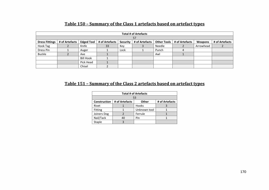
170
Table 150 – Summary of the Class 1 artefacts based on artefact types
Total # of Artefacts 57
Dress Fittings # of Artefacts Edged Tool # of Artefacts Security # of Artefacts Other Tools # of Artefacts Weapons # of Artefacts Hook Tag 2 Knife 33 Key 3 Needle 2 Arrowhead 2 Dress Pin 1 Auger 1 Lock 1 Punch 4 Buckle 2 Axe 1 Awl 1 Bill Hook 1
Pick Head 1 Chisel 2
Table 151 – Summary of the Class 2 artefacts based on artefact types
Total # of Artefacts 53
Construction # of Artefacts Other # of Artefacts Rivet 1 Hooks 3 Fitting 1 Unknown tool 1 Joiners Dog 2 Ferrule 1 Nail/Tack 40 Pin 1 Staple 3

171
Table 152 – Summary of the Class 3 artefacts based on artefact
types
Total # of Artefacts 27
Stock Iron # of Artefacts Bar 26 Billet 1
Table 153 – The classification of all the early medieval artefacts
(0F = all ferrite , 0P = all phosphoric iron, 1 = steel core flanked by ferritic or phosphoric
iron, 2 = steel edge welded to the iron back, 3 = piled or banded structure throughout
the section, 4W = a welded steel jacket around an iron core, 4C=a carburized layer
outside a iron core, 5 = all steel, 6 = pattern welded, 7 = heterogeneous)
0F 0P 1 2 3 4W 4C 5 6 7 Class 1 3 5 6 18 8 4 1 3 3 7 Class 2 8 9 1 3 3 0 1 4 0 23 Class 3 2 8 1 1 3 0 0 0 0 12
UI 0 0 0 0 1 1 0 0 0 1 Total 13 22 8 22 15 5 2 7 3 43
Table 154 – Summary of artefacts based on class
Total # of Artefacts Class 1 Artefacts Class 2 Artefacts Class 3 Artefacts UI Brent Knoll 10 5 4 1 0 Canterbury 19 7 8 4 0 Southampton 19 11 6 2 0 Thetford 21 5 11 2 3 Wharram Percy 27 8 10 9 0 Winchester 4 4 0 0 0 Worcester 12 6 5 1 0 York 28 11 9 8 0

172
Table 155 – Knife blade construction type per site
(See figure 14 for typology)
Period (Century AD) Urban /
Rural Type 0 Type 1 Type 2 Type 3 Type 4 Type 5 Pattern Welded Other Brent Knoll 10th -12th Rural 0 1 0 0 1 0 0 0 Canterbury 8th - 9th Urban 0 1 0 0 2 0 0 0 Southampton 9th - 9th Urban 0 0 6 0 0 0 0 1 Thetford 5th-9th Rural 0 0 1 1 0 0 0 0 Wharram Percy 7th-9th Rural 1 0 5 2 0 0 0 0 Winchester 9th-11th Urban 0 1 1 0 0 0 1 1 Worchester 9th-11th Urban 0 0 2 0 0 0 0 0 York 9th-11th Urban 2 1 1 1 0 0 1 0 Total 3 4 16 4 3 0 2 2

173
Table 156 – The use of heat treatment and piling in the sites
# of Class 1 Artefacts # Heat Treated # Class 1 Piled Brent Knoll 5 1 0 Canterbury 7 1 2 Southampton 11 4 4 Thetford 5 1 1 Wharram Percy 12 1 2 Winchester 4 1 1 Worchester 6 1 0 York 11 3 4
Table 157 – McDonnell’s (1992 , 1987b , 1987a) analysis of heat
treatment in knives from Coppergate, York, and Southampton
Total # of Artefacts Heat Treated % Heat Treated Southampton 14 9 64 York 47 28 60
Table 158 – Class cleanness by site
Total # of
Artefacts % Clean Class 1
% Clean Class 2
% Clean Class 3
% Clean UI
Brent Knoll 10 60 100 100 0 Canterbury 19 43 50 75 0 Southampton 19 45 50 100 0 Thetford 21 60 55 50 67 Wharram Percy 27 75 70 44 0 Winchester 4 75 0 0 0 Worcester 12 83 80 100 0 York 28 45 78 38 0
Table 159 – Smelting and smithing evidence for the sites
Site Smelting Evidence? Smithing Evidence? Smithy? Brent Knoll, Somerset No No No Canterbury, Kent No Yes No Southampton, Hampshire No Yes Yes Thetford, East Anglia No Yes No Wharram Percy, Yorkshire No Yes Yes Winchester, Hampshire No Yes Yes Worcester, Worcestershire No Yes No York, Yorkshire Yes Yes No

174
Disc Information
Included with this research is a disc with additional information that would not fit into
the printed volume. The following is a table of contents for the disc:
• Note to Examiners
• PhD Text
• PhD Data Sheets
• Assemblage data:
o Images of artefact
o X-radiographs
o Drawings
o Images of the sections
o Description of the metallurgy
o Analysis results for the sections

175
Tables and Figures Bibliography
Atkins, R. and Aileen, C. (2002) Prehistoric, Roman and Anglo-Saxon Remains at Land
Off Brandon Road, Thetford: Post-Excavation Assessment. Fulbourn:
Archaeological Field Unit.
Brisbane, M. (1988) Hamwic (Saxon Southampton): An 8th Century Port and
Production Centre. In: Hodges, R. and Hobley, B. (Eds.) The Rebirth of Towns in
the West Ad 700-1050. (Council for British Archaeology Research Report No.68)
p. 101-108. London: Council for British Archaeology.
Castagnino, V. (2008). An Investigation in the White Weld Line Phenomenon. MSc
thesis University of Bradford.
Cleere, H. and Crossley, D. (1995) The Iron Industry of the Weald. Vol. 1. Mertan
Priory Press.
Dalwood, H. and Edwards, R. (Eds.) (2004) Excavations at Deansway, Worcester, 1988-
89: Romano British Small Town to Late Medieval City. (Council for British
Archaeology Research Report 139) York: Council for British Archaeology.
Hall, R. (1994) Viking Age York. (English Heritage) Bath: B T Batsworth Ltd/English
Heritage.
Hansen, M. (1958) Constitution of Binary Alloys. London: McGraw-Hill Book Company,
Inc.
James, E. (2001) Britain in the First Millennium. London: Hodder Arnold.
176
Leahy, K. (2003) Anglo-Saxon Crafts. Stroud: Tempus Publishing
McDonnell, J. G. (1987a) Analysis of Eight Iron Knives and Four Other Tools from
Hamwih, Southampton. (Ancient Monuments Laboratory Report 137/87)
Centre for Archaeology. English Heritage.
McDonnell, J. G. (1987b) Metallurgical Analysis of Six Iron Knives from Hamwih,
Southampton. (Ancient Monuments Laboratory Report 93/87) Centre for
Archaeology, English Heritage.
McDonnell, J. G. (1992) The Metallurgical Analysis of the Ironworking Slags and Iron
Artefacts. In: Ottaway, P. (Ed.) Anglo-Scandinavian Ironwork from Coppergate,
York. Vol. 17/6 p. York: York Archaeological Trust/Council of British
Archaeology
Milne, G. and Richards, J. D. (1992) Two Anglo-Saxon Buildings and Associated Finds.
(Wharram: A Study of the Settlement on the Yorkshire Wolds) Vol. VII. Leeds:
York University Archaeological Publications
Ottaway, P. (1992) Anglo-Scandinavian Ironwork from 16-22 Coppergate. (The
Archaeology of York the Small Finds) Vol. 17/6. York: York Archaeological Trust
for Excavation and Research.
Pleiner, R. (2000) Iron in Archaeology the European Bloomery Smelters. Praha:
Archeologicky Ustav AV CR.
Reynolds, A. (1999) Later Anglo-Saxon England Life and Landscape. Stroud: Tempus
Publishing.

177
Rulton, S. (2003). An Investigation into the Metallurgy of a Group of Anglo-Saxon and
Medieval Knives from Winchester. Undergraduate Dissertation. University of
Bradford.
Samuels, L. E. (1999) Light Microscopy of Carbon Steel. Metal Park: American Society of
Metals.
Tatton-Brown, T. (1992) Canterbury and the Early Medieval Towns of Kent. In: Rigold,
S. E. (Ed.) Archaeology in Kent to AD 1500. (Council for British Archaeology
Research Report 48) p. 79-83. London: Council for British Archaeology
Walters, B. (1999) The Forest of Dean Iron Industry: 1st to 4th Centuries A.D. (Dean
Archaeological Group Occasional Publication No. 4) Lydney: Dean
Archaeological Group.


![Reflection Removal Using Ghosting Cuesopenaccess.thecvf.com/content_cvpr_2015/papers/Shih... · 2017-04-04 · and Schechner [9]. They quantified the ghosting in both the transmission](https://static.fdocuments.in/doc/165x107/5ea4ec2a1ea31f3cc1646814/reflection-removal-using-ghosting-2017-04-04-and-schechner-9-they-quantiied.jpg)