An API for Smart Objects and Multimodal User Interfaces ...
94
An API for Smart Objects and Multimodal User Interfaces for the Smart Home and Office by Carlos R. Rubio SB. Electrical Engineering and Computer Science & Physics, MIT (2014) Submitted to the Department of Electrical Engineering and Computer Science in Partial Fulfillment of the Requirements for the Degree of Master of Engineering in Electrical Engineering and Computer Science at the Massachusetts Institute of Technology June 2015 © 2015 Massachusetts Institute of Technology. All rights reserved. Author: _________________________________________________________________ Department of Electrical Engineering and Computer Science May 21, 2015 Certified by: __________________________________________________________________ Kent Larson, Principal Research Scientist, Thesis Supervisor May 21, 2015 Accepted by: __________________________________________________________________ Prof. Albert R. Meyer, Chairman, Masters of Engineering Thesis Committee
Transcript of An API for Smart Objects and Multimodal User Interfaces ...
An API for Smart Objects and Multimodal User Interfaces
for the Smart Home and Office
by Carlos R. Rubio
SB. Electrical Engineering and Computer Science & Physics, MIT (2014)
Submitted to the
Department of Electrical Engineering and Computer Science
in Partial Fulfillment of the Requirements for the Degree of
Master of Engineering in Electrical Engineering and Computer Science
at the
Massachusetts Institute of Technology
June 2015
© 2015 Massachusetts Institute of Technology. All rights reserved.
Author: _________________________________________________________________
Department of Electrical Engineering and Computer Science
May 21, 2015
Certified by: __________________________________________________________________
Kent Larson, Principal Research Scientist, Thesis Supervisor
May 21, 2015
Accepted by: __________________________________________________________________
Prof. Albert R. Meyer, Chairman, Masters of Engineering Thesis Committee
2
An API for Smart Objects and Multimodal User Interfaces for the Smart Home and Office
by
Carlos Roberto Rubio
Submitted to the Department of Electrical Engineering and Computer Science
on May 22, 2015, in partial fulfillment of the
requirements for the degree of
Master of Engineering in Electrical Engineering and Computer Science
Abstract As more people move to cities, space is becoming more limited and expensive. Robotic furniture can
increase functionality and optimize space, allowing spaces to feel as if they were three times the size.
These mechatronic systems need capable electronics and connected microcontrollers to bring furniture to
the Internet of Things (IoT). We present these electronics and firmware for three smart robotic spaces.
These smart spaces need powerful software and computing systems to enable the transformations and
give magic to the space. We present software written for three smart robotic spaces. The right user
interfaces are vital for rich user experience. User studies with different smart home user interfaces show
that although tactile interfaces are the most reliable and easiest to work with, people are hopeful for
sufficiently robust gestural and speech interfaces in future smart homes. The urban homes and offices of
the future are smart, customizable, and robotic.
Thesis Supervisor: Kent Larson
Title: Principal Research Scientist, Program in Media Arts and Sciences
3
Acknowledgements
I would like to thank all who made this thesis possible.
First, my deepest thanks to my supervisor, Kent Larson, for taking me into the group and all his guidance
and support throughout my stay. It was a pleasure to be part of the group and do research with a
multidisciplinary team of talented individuals.
I would like to thank Hasier Larrea, the CityHome project manager, for all his support and guidance, both
technical and professional, throughout my three semesters. I have grown personally and professionally
under his leadership and am excited to continue in our endeavors.
I would like to thank IKEA for sponsoring me during this project.
I am very grateful to have worked along inspiring and gifted researchers throughout my time in the
CityHome team; Oier Ariño, Matthew Daiter, Spencer Boone, Yousif Rouben, Dennis Garcia, Daniel
Prado, Dalitso Banda, Chad Bean, Eric Ponce, Ivan Fernandez, and Luis Alonso, it was a pleasure
working with you and getting to know you.
Kindest regards go to all my friends for their continuous encouragement and for bringing so much
happiness into my life. Shout out to all my friends in 7C; you all made my time at MIT so much better.
Thanks to Yasmin Chau and Monika Avello for keeping me going and helping me balance my academic
and social life.
Affectionate gratitude to Claire Belant for her kind encouragement and for keeping me smiling, even
through the final tough times.
Finally, and most importantly, I wish to thank my family for always standing by my side. Thanks to my
brother and sister, Daniel and Isa, for all the love, joy, and motivation they gave me. Thanks to my
parents and their unconditional love, support, and sacrifice, for raising us and giving us their all. I
dedicate this thesis to them, gracias con todo mi ser.

4
This page intentionally left blank.
5
Contents
Abstract ........................................................................................................................................................ 2
1 Introduction .............................................................................................................................................. 9
1.1 Problem ............................................................................................................................................ 10
1.2 Approach ......................................................................................................................................... 10
1.3 Thesis Overview .............................................................................................................................. 11
2 Background ............................................................................................................................................ 12
2.1 Motivation ........................................................................................................................................ 13
2.2 Current Work .................................................................................................................................. 14
2.3 Original Design ................................................................................................................................ 15
3 User Interfaces ....................................................................................................................................... 18
3.1 Tactile ............................................................................................................................................... 19
3.1.1 Switches ..................................................................................................................................... 19
3.1.2 Force-sensing resistors ............................................................................................................. 20
3.2 Gesture recognition ......................................................................................................................... 21
3.2.1 Kinect ........................................................................................................................................ 23
3.2.2 Rule-based state machine with 3-D points and vectors ........................................................ 23
3.3 Speech recognition .......................................................................................................................... 26
3.4 Visual ................................................................................................................................................ 27
3.4.1 CityOffice Visual Interface ..................................................................................................... 27
3.4.2 CityHome 2 Graphical Programming Interface ................................................................... 29
3.5 Feedback .......................................................................................................................................... 31
3.5.1 LED Lighting ............................................................................................................................ 31
3.5.2 Speech Synthesis ....................................................................................................................... 32
4 Electronics and Microcontrollers ......................................................................................................... 34
4.1 Purpose and Importance ................................................................................................................ 35
4.2 Execute, Manage, Perform ............................................................................................................. 35
4.2.1 Execute ...................................................................................................................................... 35
4.2.2 Manage ...................................................................................................................................... 37
4.2.3 Perform ..................................................................................................................................... 37
4.3 Capabilities ...................................................................................................................................... 38
4.3.1 Inputs ........................................................................................................................................ 39
4.3.2 Outputs ...................................................................................................................................... 39
4.3.3 Connectivity .............................................................................................................................. 40
6
4.4 Requirements ................................................................................................................................... 41
4.4.1 Safety ......................................................................................................................................... 41
4.5 CityHome 1 ...................................................................................................................................... 42
4.6 CityOffice ......................................................................................................................................... 44
4.6.1 Motor Drivers ........................................................................................................................... 44
4.6.2 Height Control .......................................................................................................................... 45
4.6.3 Spark Core Microcontrollers .................................................................................................. 46
4.6.4 Limitations ................................................................................................................................ 47
4.7 CityHome 2 ...................................................................................................................................... 48
4.7.1 Control Loop ............................................................................................................................ 49
4.7.2 Communication ........................................................................................................................ 50
4.7.3 Resource Representation ......................................................................................................... 51
4.7.4 Limitations ................................................................................................................................ 52
5 Software .................................................................................................................................................. 53
5.1 Purpose and Importance ................................................................................................................ 54
5.2 Microcontroller vs. Microprocessor vs. Processor ....................................................................... 54
5.2.1 Microprocessor ......................................................................................................................... 54
5.2.2 Processor ................................................................................................................................... 55
5.3 Capabilities ...................................................................................................................................... 55
5.3.1 Communication ........................................................................................................................ 55
5.3.2 Data Management .................................................................................................................... 56
5.4 CityHome 1 ...................................................................................................................................... 57
5.4.1 Processor Specs ........................................................................................................................ 57
5.4.2 Software Choice........................................................................................................................ 57
5.4.3 Elements .................................................................................................................................... 57
5.4.4 Algorithms ................................................................................................................................ 59
5.4.5 Limitations ................................................................................................................................ 60
5.5 CityOffice ......................................................................................................................................... 60
5.5.1 Processor Specs ........................................................................................................................ 60
5.5.2 Software Choice........................................................................................................................ 60
5.5.3 Elements .................................................................................................................................... 61
5.5.4 Algorithms ................................................................................................................................ 62
5.6 CityHome 2 ...................................................................................................................................... 64
5.6.1 Processor Specs ........................................................................................................................ 64
5.6.2 Software Choice........................................................................................................................ 64
7
5.6.3 Elements .................................................................................................................................... 66
5.6.4 Algorithms ................................................................................................................................ 67
5.6.5 Limitations ................................................................................................................................ 70
6 User Studies ............................................................................................................................................ 71
6.1 Components Tested and Surveyed ................................................................................................ 72
6.1.1 Learnability .............................................................................................................................. 72
6.1.2 Ease............................................................................................................................................ 72
6.1.3 Satisfaction ................................................................................................................................ 73
6.2 Experiment ...................................................................................................................................... 73
6.3 Results and Conclusions ................................................................................................................. 73
6.3.1 Performance ............................................................................................................................. 73
6.3.2 Usability .................................................................................................................................... 77
6.3.3 Implementation Notes .............................................................................................................. 83
6.3.4 Improvements ........................................................................................................................... 85
6.4 Other Qualitative Results and Conclusions .................................................................................. 86
7 Conclusion .............................................................................................................................................. 91
7.1 Application Spaces .......................................................................................................................... 92
7.2 Impacts and Milestones .................................................................................................................. 92
Bibliography .............................................................................................................................................. 94
8
List of Figures
Figure 1: Core of the CityHome 2 API. ...................................................................................................... 17
Figure 2: Image of a square FSR, sold by Sparkfun. https://www.sparkfun.com/products/9376 ............... 21
Figure 3: A Leap Motion and its visualization. https://www.leapmotion.com/ .......................................... 22
Figure 4: A Microsoft Kinect v1. http://electronics.howstuffworks.com/microsoft-kinect2.htm ............... 23
Figure 5: Table moving out in the CityHome 1 prototype because of pull gesture. ................................... 25
Figure 6: A CityOffice Kubo transforming into a sitting, deployed desk. .................................................. 28
Figure 7: Screenshot of Kubo website. ....................................................................................................... 29
Figure 8: CityHome website. ...................................................................................................................... 30
Figure 9: Node-RED CityHome 2 GPI. ...................................................................................................... 31
Figure 10: CityHome 1 prototype giving visual feedback with LED lights. .............................................. 32
Figure 11: A simple motor controller from Pololu. https://www.pololu.com/product/1378 ...................... 36
Figure 12: CityHome 1 prototype. .............................................................................................................. 42
Figure 13: Arduino Mega. http://www.arduino.cc/en/Main/arduinoBoardMega ....................................... 43
Figure 14: CityOffice prototype space. ....................................................................................................... 44
Figure 15: Spark Core microcontroller, Wi-Fi included. https://www.particle.io/prototype ...................... 47
Figure 16: CityHome 2 prototype. .............................................................................................................. 49
Figure 17: First page of Kubo website. ....................................................................................................... 63
Figure 18: Complexity of CityHome 2 prototype software. ....................................................................... 64
Figure 19: CityHome ROS node framework. ............................................................................................. 65
Figure 20: CityHome has more than a million views on YouTube. Image courtesy of Hasier Larrea. ...... 93
Figure 21: Examples of press attention for CityHome. Image courtesy of Hasier Larrea. ......................... 93

9
Chapter 1
1 Introduction

10
1.1 Problem
We are living in a rapidly urbanizing world. More and more people are moving from rural areas to cities.
“By 2025, cities are expected to need to build floor space equivalent to 85% of today’s building stock.”
(Dobbs, et al., 2012) This creates a host of problems that negatively affect urban livability, like sprawl,
pollution, and cramping.
Space and square footage are one of the most precious commodities of big and growing cities.
There are spaces for living and working. Most spaces, however, are static. Once buildings and rooms are
assigned a specific purpose, their furniture, configuration, and usage becomes fixed. This static nature
results in underutilization. Kitchens are usually only used during meals; bedrooms are used during the
night, living rooms during the day, etc. Because space is not being used optimally, more space and rooms
are needed to have all the required functions people need and to maintain their quality of life. The price of
square footage in big and growing cities therefore skyrockets, especially in the downtowns and most
desired locations.
1.2 Approach
A current, yet unsustainable, solution to fitting more people and functions into cities is to shrink the
square footage of rooms. This, however, leads to a poorer quality of life and brings a host of other
problems. Having transformable, dynamic, and smart furniture elements and objects can better solve this
problem. Furniture that can translate horizontally and vertically can optimize space and allow spaces to be
reconfigured on demand. Rooms can have multiple functions and purposes. People can live in smaller
spaces, yet feel as if they were living large and have a higher quality of life. Moreover, these smart
furniture objects can be connected to the Internet and talk to each other, allowing rooms to reconfigure
seamlessly and intelligently, people to add their desired sensors and peripherals, data to be collected to
11
improve quality of life, and programmability to allow users to customize their space to behave according
to their needs and wants.
1.3 Thesis Overview
The MIT Media Lab’s Changing Places group’s CityHome project aims to bring attention to the problem
and further the solutions by developing the technologies behind these robotic furniture elements and
building and highlighting examples of them.
These furniture elements need brains, powerful and capable microcontrollers that can control
them with safety, allow users to add on desired components, and connect to, send data over, and receive
commands from networks and the Internet. The smart rooms also require software, a unifying API that
makes these elements programmable and accessible over the Internet. User interfaces are also needed to
allow users to naturally interact with the furniture and smart objects and contribute to the user experience.
This thesis explores some of the technology developed for the CityHome project from the
beginning of spring 2014 to the end of spring 2015. It consists mostly of the electrical, electronic,
firmware, and software technologies of the CityHome 200 square foot apartment prototype (Spring 2014),
CityOffice prototype (Fall 2014), and CityHome 300 square foot apartment prototype (Spring 2015). It
also explores some of the user interfaces and experiences developed for the prototypes. Lastly, it details
experimental user studies that tested these interfaces on performance, usability, and user satisfaction and
elaborates on the results and conclusions.
12
Chapter 2
2 Background
13
2.1 Motivation
Extreme urbanization is happening now and will continue over the next few decades. This brings along a
host of consequences for cities and urban spaces, which overall degrade the quality of life. They include
sprawl, congestion, pollution, and overall higher costs of living. High performance, entrepreneurial, and
livable urban districts are and will continue to be important and the main drivers of cities’ and nations’
prosperities. The right density, proximity to the right mix of amenities, and population diversity are keys
to enabling these types of urban districts. We must address current problems, and foresee future ones,
concerning living spaces, working spaces, food and energy production, distribution, and consumption,
and transportation.
The housing problem is a particularly important and interesting one. As cities continue to grow,
space becomes more limited and prices skyrocket. Young professionals, working middle class people who
are starting their careers and have limited resources, are especially negatively impacted, as they cannot
afford to live in the expensive urban centers, where they most desire to be. This also applies to singles,
elderly, and the working class.
There are some current solutions trying to address the problem of space optimization. One
solution is to use micro units. Micro units are small apartments, on the order of less than 300 square feet.
They have just enough space for the essentials: a small table/desk, a bed, a mini kitchen, a small
bathroom. While they are more affordable, they are also less desirable to live in. There is less space for
everything, and therefore less functionality. This overall leads to a poorer quality of life.
Another solution is transformable furniture. Examples of classic transformable furniture are
murphy beds and sofa beds. Examples of new transformable furniture are movable walls and
counterbalanced beds. Mechatronic furniture also exists. However, all these solutions fall short. They are
expensive, which misses the point of solving problems for people who could not otherwise afford to live
in larger places. They are difficult to work with. Murphy beds and sofa beds, for example, require users to
14
make their beds very neatly, maybe attach cumbersome straps, and exert much physical force to
reconfigure the furniture. All these solutions are missing connectivity, programmability, and the
experience layer. The elements are dumb; they force the user to adapt to them, rather than adapting to the
user. While some of these solutions are great for temporary use, they do not work well long term; people
using a sofa bed or futon as a permanent bed will likely not enjoy reconfiguring it on a daily basis.
A solution capable of overcoming these problems is robotic furniture. Transformable smart home
furniture and objects can act as space reconfigurators to maximize functionality and make people feel like
they have much more space. Robotic furniture can come equipped with rich, natural, easy, and effective
user interfaces, which translate into great user experiences. People not only feel that they have more
space; they feel like they have better space. Examples of these types of furniture are a robotic wall with
motors, a cantilevered motorized desk and bed, and a robotic movable closet or storage unit.
The CityHome team has been exploring this solution for some time and has created smart room
prototypes highlighting the potential of these furniture elements and the impact they can have on future
urban spaces. These mechatronic systems need suitable electronics and software to power them and
connect them to the Internet of Things (IoT).
2.2 Current Work
There are plenty of smart home automation products out there: lights, thermostats, locks, and all types of
sensors, to name a few. There is a lot of hype about these devices and their connectivity to the IoT.
Except for custom, expensive, one-off solutions, no one is talking about or working on robotic furniture.
However, robotic furniture is not only fitting of these technologies and connectivity to the IoT, but it
could need it more and have more use cases with it, as furniture most intimately affect our homes. As
such, no one is working on the technologies, electronics, and software for robotic furniture; the CityHome
project researchers are developing them.
15
Part of the problem in the field concerning electronics and software is diversity and lack of
standardization. Different companies develop different technologies, and these technologies do not play
well with technologies from other parties.
There are no agreed upon communication peripherals and protocols for device connectivity.
Therefore, there exists a plethora of peripherals and protocols on the market; Bluetooth, Bluetooth LE,
Wi-Fi, ZigBee, and Z-Wave are some. Each have pros and cons. Wi-Fi, for example, is ubiquitous and
allows for direct Internet connectivity, but it can be more power-hungry than other protocols. Z-Wave is
less ubiquitous but implements mesh networking, allowing for a wider area of coverage throughout the
home or building.
Another fractured smart home automation area is the software, firmware, and APIs that will
power and drive the IoT devices of the future. There is no consensus, and companies are developing their
own, sometimes open, sometimes propriety, software and frameworks for these devices. Apple has
introduced HomeKit, Google is building a toolkit around Nest and has built The Physical Web, Samsung
is building a toolkit around the SmartThings infrastructure, and other companies like Revolv and Quirky
(Wink) are building their own APIs. Even conglomerates of companies have made alliances intended to
steer the future direction of IoT. Examples include IoTivity and the Allseen Alliance. However, there is
no popular or widely adopted platform, and the field does not yet seem to be converging.
Lastly, most user interfaces for smart home automation products today are either tactile on the
device or visual on web apps or smart phone apps. These are rather limiting in terms of user experience.
They both force the user to either be physically touching the device or interacting with a computer or
phone, and they may be inefficient and inconvenient for the user.
2.3 Original Design
The CityHome team has come to conclude that the best communication platform policy is to be
agnostic and try to develop technology that will play well with others, or at least allow that connectivity
16
as easily as possible. Some commercial smart home automation companies have adopted this mindset.
SmartThings, for example, sells a hub equipped with multiple antennas supporting many communication
protocols, like the ones listed above. They abstract that away and present the user and programmer with
what they really want, access and control of their devices.
Regardless, a communication platform choice was necessary for the creation of the prototypes.
We decided that Wi-Fi should be the platform for CityHome. Wi-Fi has many benefits. It is ubiquitous;
many modern buildings have Wi-Fi routers whose range extends throughout most or all of the building.
Wi-Fi provides the devices direct access to the Internet, and with IPv6, addressing these devices and
connecting them directly to the IoT will not be a problem. Wi-Fi allows us to leverage the existing
hardware and software infrastructure that has already been built, tested, and scaled around it. Wi-Fi chips
for microcontrollers are easy to get and use, and most programming languages provide libraries that allow
for network and Internet communication, allowing programmers to write apps for these devices.
For software platform, the CityHome team again came to conclude that agnosticism is the best
policy. Building software such that it presents other programmers with an easy, structured, standardized
API and that can leverage third parties API but abstract them into similar or identical form factors as the
novel elements will lead to better, more scalable interactions and integrations. Therefore, we worked to
choose multiple programming languages and platforms (ROS, Node.js) across the prototypes, integrate a
third party API (SmartThings), leverage multiple software libraries, including Microsoft Kinect SDK,
Microsoft Speech SDK, and Node-RED, and write an API allowing easy access to a smart home database
and its microcontrollers.
We believe that different user interfaces and more choices can lead to better user experiences.
Gestural and speech recognition technologies, for example, can open up a world of magical experiences.
Gesturing towards a device can cause it to move, transform, or change. Speaking at lights and furniture
can do the same. Even tactile interfaces that are more metaphorically correct can lead to more natural user
17
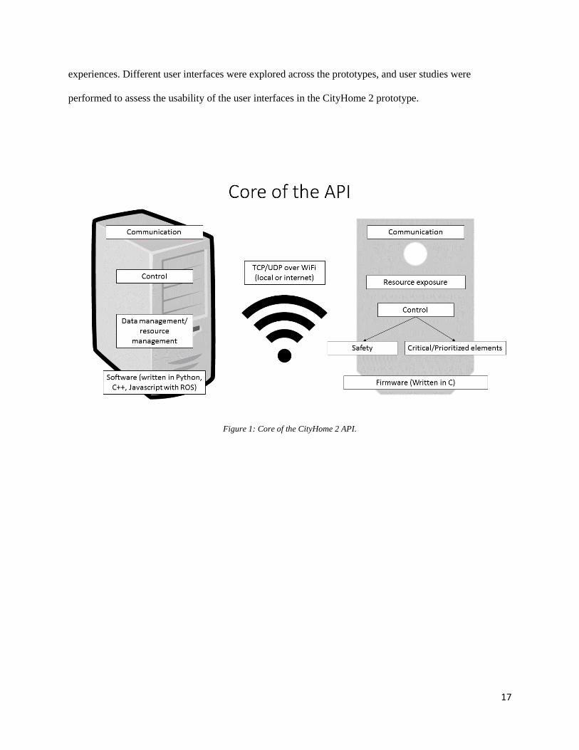
experiences. Different user interfaces were explored across the prototypes, and user studies were
performed to assess the usability of the user interfaces in the CityHome 2 prototype.
Figure 1: Core of the CityHome 2 API.
18
Chapter 3
3 User Interfaces
19
A vital ingredient in the making of robotic furniture are the user interfaces (UIs). Without good UIs, there
is no good user experience (UX). People would not like to live in a difficult, unnatural robotic space any
more than in a small, static one. This section explores the UIs that can be used with these types of robotic
elements and serves as a primer for the technical details of their integration into the CityHome and
CityOffice prototypes covered in the following chapters. The UIs are divided into four categories: tactile,
gestural, speech, and visual. Additionally, an important element of good UX, feedback, is discussed.
3.1 Tactile
Tactile interfaces are perhaps the most common and popular of all user interfaces in all sorts of products
people interact with. Touch is a very well developed human sense; it is very natural and innate. Good
tactile interfaces allow people to use and interact with devices seamlessly, efficiently, and naturally.
Integrated tactile interfaces are usually simple. The most common ones are buttons or switches.
They allow users to toggle the state of the device. The toggling can be as simple as on and off or as
complicated as navigating a menu.
3.1.1 Switches
Switches are popular because of their simplicity. They are cheap, easy to integrate, and universal; they are
used in one capacity or another in many devices. They can be mechanical or electrical and are quick and
easy to use. They also afford the user direct control over the device and require the presence of the user
for operation (or at least the start of operation), which can be an important safety feature in many
applications, like in motorized heavy furniture translation.
Two common types of switches in electronic applications are single pole, single throw (SPST)
switches and single pole, double throw (SPDT) switches. Although simple and appropriate for many
products and use cases, switches have their limitations. They usually do not significantly enhance the user
20
experience. They also do not afford natural interactions; switches do not metaphorically (Marcus, 1998)
integrate with the device functions and do not feel comfortable to use. Although integrated for safety
reasons in the CityHome and CityOffice prototypes, switches were not used as the primary tactile user
interface.
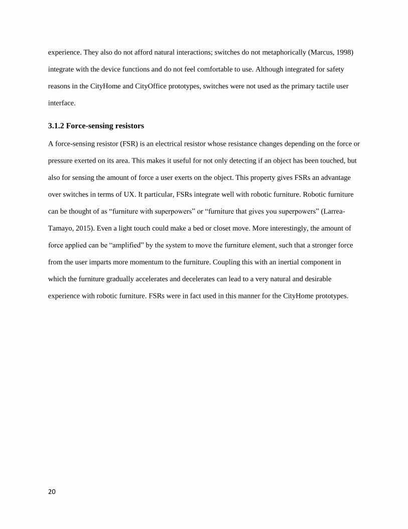
3.1.2 Force-sensing resistors
A force-sensing resistor (FSR) is an electrical resistor whose resistance changes depending on the force or
pressure exerted on its area. This makes it useful for not only detecting if an object has been touched, but
also for sensing the amount of force a user exerts on the object. This property gives FSRs an advantage
over switches in terms of UX. It particular, FSRs integrate well with robotic furniture. Robotic furniture
can be thought of as “furniture with superpowers” or “furniture that gives you superpowers” (Larrea-
Tamayo, 2015). Even a light touch could make a bed or closet move. More interestingly, the amount of
force applied can be “amplified” by the system to move the furniture element, such that a stronger force
from the user imparts more momentum to the furniture. Coupling this with an inertial component in
which the furniture gradually accelerates and decelerates can lead to a very natural and desirable
experience with robotic furniture. FSRs were in fact used in this manner for the CityHome prototypes.

21
Figure 2: Image of a square FSR, sold by Sparkfun. https://www.sparkfun.com/products/9376
3.2 Gesture recognition
Gestural interfaces are novel, interesting, and under continuous development and refinement. Body
language is an important facet of communication between humans. Getting computers to understand body
movements can lead to better and richer user experiences. There are a number of devices that can

22
recognize poses of the body or body parts, such as the Leap Motion, which detects the hands, and the
Microsoft Kinect, which detects the body. Although gestures tend to be easily recognized within cultures,
and some gestures are universal, they are considerably more difficult to deal with for computers. At the
lowest level, computers just see 3-D positions of important bodily elements, like skeletal joints. The
programmer must then decide how this data is interpreted and analyzed to detect gestures.
Figure 3: A Leap Motion and its visualization. https://www.leapmotion.com/
People tend to be in their element when they are at home. Many people become comfortable and
relaxed, and some like to disconnect from electronics such as computers and cell phones. Most modern
smart home products have a graphical interface one can use on the phone or web browser for control.
Unfortunately, this forces the user to carry and use the phone when an interaction is desired. Gesture
recognition can therefore become a very important UI, giving the user the freedom to use his or her body
at ease to interact with the smart objects. A Microsoft Kinect was utilized for this purpose in the
CityHome prototypes.

23
3.2.1 Kinect
Figure 4: A Microsoft Kinect v1. http://electronics.howstuffworks.com/microsoft-kinect2.htm
The Kinect allows for gesture recognition via skeletal tracking of the people in the room. It provides the
X, Y, and Z coordinates of skeletal joints of the person relative to the Kinect, like head, hands, elbows,
and shoulders. Programming rules about the relative locations of the joints over time is one way to
program for gestures and is the way the CityHome prototypes were implemented. The Kinect also allows
for speech recognition, as it has a high quality multi-array microphone that can pick up speech throughout
the room.
3.2.2 Rule-based state machine with 3-D points and vectors
To figure out what is the best methodology and algorithm for gesture detection and analysis, one must
first figure out how the user would interact gesturally with the robotic furniture. In other words, the
programmer must write code according to how the user wants to behave (within reason, of course), and
not force the user to interact with the system solely according to how the programmer designed it. In
thinking about this, we decided to divide the interaction into three phases: attention, selection, action.
24
In the attention state, the user must perform a very specific gesture to wake the system and get its
attention. This reduces false positives and prevent the system from reacting to unintentional gestures. As
such, the wake gesture must be very particular and something that people would not ordinarily do. This
gesture should be maintained for some amount of frames.
In the selection state, the user must select an object. Pointing is the most obvious way of doing
this. To determine which object is being pointed at, we made a list with all the X, Y, and Z coordinates of
all the controllable objects relative to the Kinect. During each frame, a vector is drawn from all points to
the user’s chest or right elbow. Another vector is drawn from the user’s right elbow or shoulder to the
right hand. The vectors are normalized. Then, the dot product of each object vector and the user vector is
taken. A dot product value close to -1 implies that the vectors are antiparallel, or pointing directly at each
other, which implies that the user is pointing at that object with his or her right arm. If an object vector
dot product consistently falls below a threshold for some amount of frames, then the user has selected the
object.
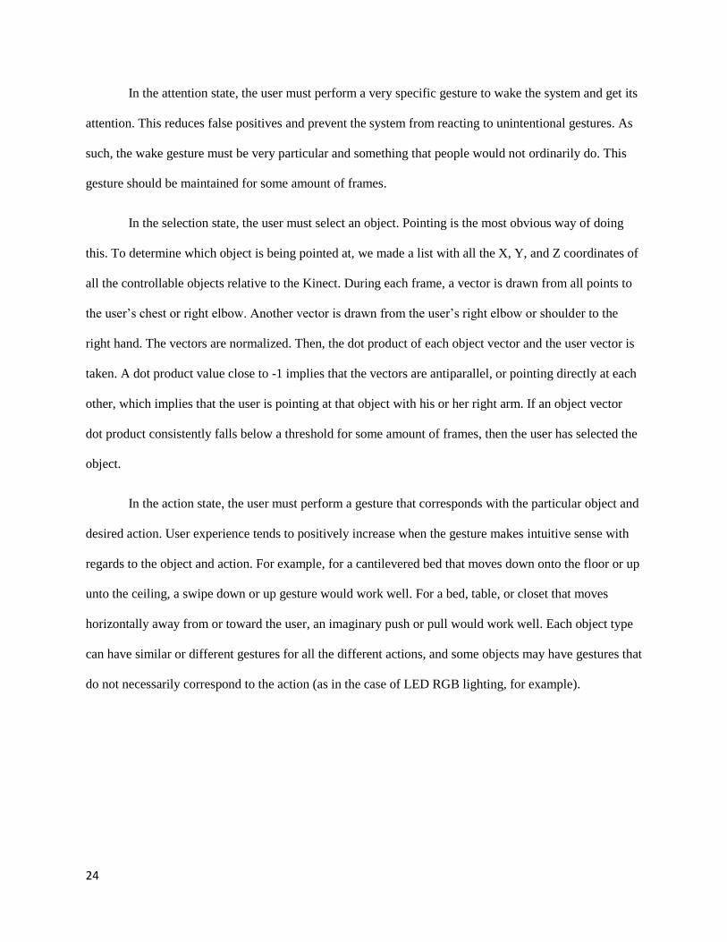
In the action state, the user must perform a gesture that corresponds with the particular object and
desired action. User experience tends to positively increase when the gesture makes intuitive sense with
regards to the object and action. For example, for a cantilevered bed that moves down onto the floor or up
unto the ceiling, a swipe down or up gesture would work well. For a bed, table, or closet that moves
horizontally away from or toward the user, an imaginary push or pull would work well. Each object type
can have similar or different gestures for all the different actions, and some objects may have gestures that
do not necessarily correspond to the action (as in the case of LED RGB lighting, for example).
25
Figure 5: Table moving out in the CityHome 1 prototype because of pull gesture.
Using this methodology, the system can be described as a rule-based state machine. All gestures
are detected via rules; the 3-D Cartesian coordinates of skeletal joints of the body are extracted, and
relationships are drawn between the positions of different joints or past and current positions of joints. For
example, if the y-coordinate of the right hand has a higher value than the y-coordinate of the head, this
can be detected as raising the right hand above the head, or an attention-getting gesture. The initial state is
the sleeping/attention state, where the system is monitoring for the wake gesture. The selection state is
the second state, where the system is monitoring where the user is pointing. The action state is the final
state, where the system is monitoring for a gesture that corresponds to an action for the object. In this
way, gestures allow the user to interact with the furniture naturally and without the need for a phone or
computer.
26
3.3 Speech recognition
Speech interfaces, like gestural interfaces, are new, interesting, and under continuous refinement. In some
cases, like low noise environments, they are more accurate and easier to work with than gestural
interfaces. Speech is the primary method of communication between humans, and having computers
understand speech, and the context too, can lead to rich user experiences. Speech recognition can work
with computers with the right software and a connected microphone. Example software libraries include
the HTML5 Web Speech API, CMU Sphinx, Microsoft Speech Platform SDK, WAMI Toolkit,
OpenEAR: Munich Open-Source Emotion and Affect Recognition Toolkit, and OpenEars. The Microsoft
Speech SDK and a Microsoft Kinect were used for speech recognition in the CityHome prototypes.
The Microsoft Speech SDK supports two speech recognition models: dictation and fixed
grammar. The dictation model recognizes all words supplied in the language pack (the English language
pack from Microsoft was used). As such, it is the broader and more versatile of the two models. It would
allow the user to phrase a command however he or she chooses, only needing to include certain
keywords. For example, the programmer could specify “bed”, “down”, “sleep” as keywords that when
found in a phrase would make the bed go down. “Move the bed down”, “bed down”, and “I want to
sleep” could all trigger the bed to move down. The dictation model, however, is also the slower and less
accurate of the two. The fixed grammar model recognizes only the phrases specified by the programmer.
Therefore, the user is limited to saying the phrases the programmer specified; saying a similar phrase or
phrase with synonyms would not work (at least not usually). The grammar model is faster and more
accurate, since the system is only looking for a few words rather than all possible words. For the
CityHome prototypes, the fixed grammar model was used.
As with the gestural interface, a key word or phrase must be said to wake the system. This
reduces false positives. This is especially useful in our lab setting, where we often do demos and talk
about how the system moves and operates using same and similar phrases to the ones that trigger the
actions. Additionally, the Microsoft Speech SDK returns a confidence score with the detection, a value
27
that ranges from 0.0 to 1.0. A value of 1.0 implies that the system is perfectly sure that the phrase was
said (this value is never seen in practice). The programmer can specify a threshold that this value must
exceed to perform the corresponding operation.
Although a fixed grammar model is less natural than a dictation model, the gains in speed and
accuracy are worth it, and a user can quickly learn the phrases for interaction or maybe even specify
which phrases he or she would want in the grammar model.
3.4 Visual
Visual interfaces are one of the most popular interfaces for many electronics, especially Internet
connected ones. Visual interfaces are very useful for displaying information and can be used effectively
for input, communication, and control. Unfortunately, they constrain the user to have a computer,
monitor, mouse, keyboard, and/or phone.
Because of their importance and ubiquity in computer-controlled systems, computer screens were
used in all three prototypes. However, tactile, gestural, and speech interfaces were included when possible
to serve as primary modes of interaction. For the CityHome 1 prototype, a projector highlighted the
potential of projecting information on home surfaces and possibly having a camera-assisted touch
interface. However, this was not used for user input.
3.4.1 CityOffice Visual Interface
The CityOffice prototype was an example of how robotic furniture elements can enhance office space.
The main furniture element was a robotic desk called a Kubo. The desk was mobile; it had motorized
wheels to allow it to navigate the space. The desk had automated legs that allowed it to transform between
a cube, a sitting desk, and a standing desk. Lastly, the desk had flaps that allowed for variable desk space.
28
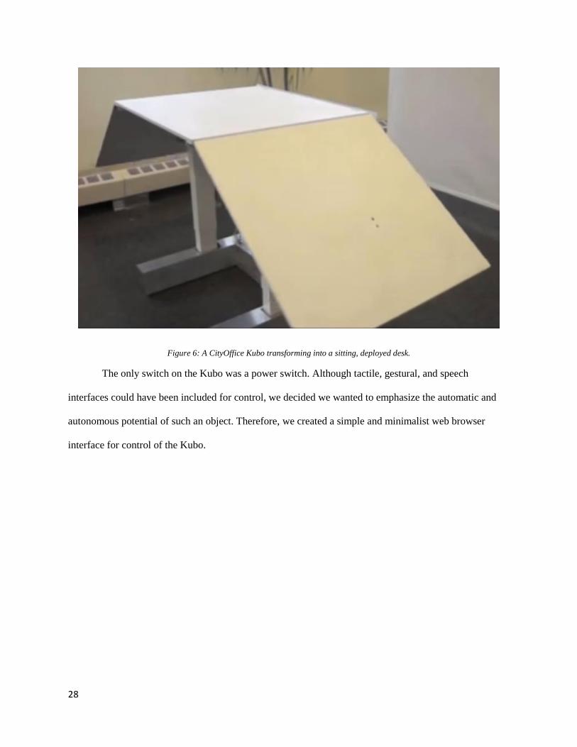
Figure 6: A CityOffice Kubo transforming into a sitting, deployed desk.
The only switch on the Kubo was a power switch. Although tactile, gestural, and speech
interfaces could have been included for control, we decided we wanted to emphasize the automatic and
autonomous potential of such an object. Therefore, we created a simple and minimalist web browser
interface for control of the Kubo.
29
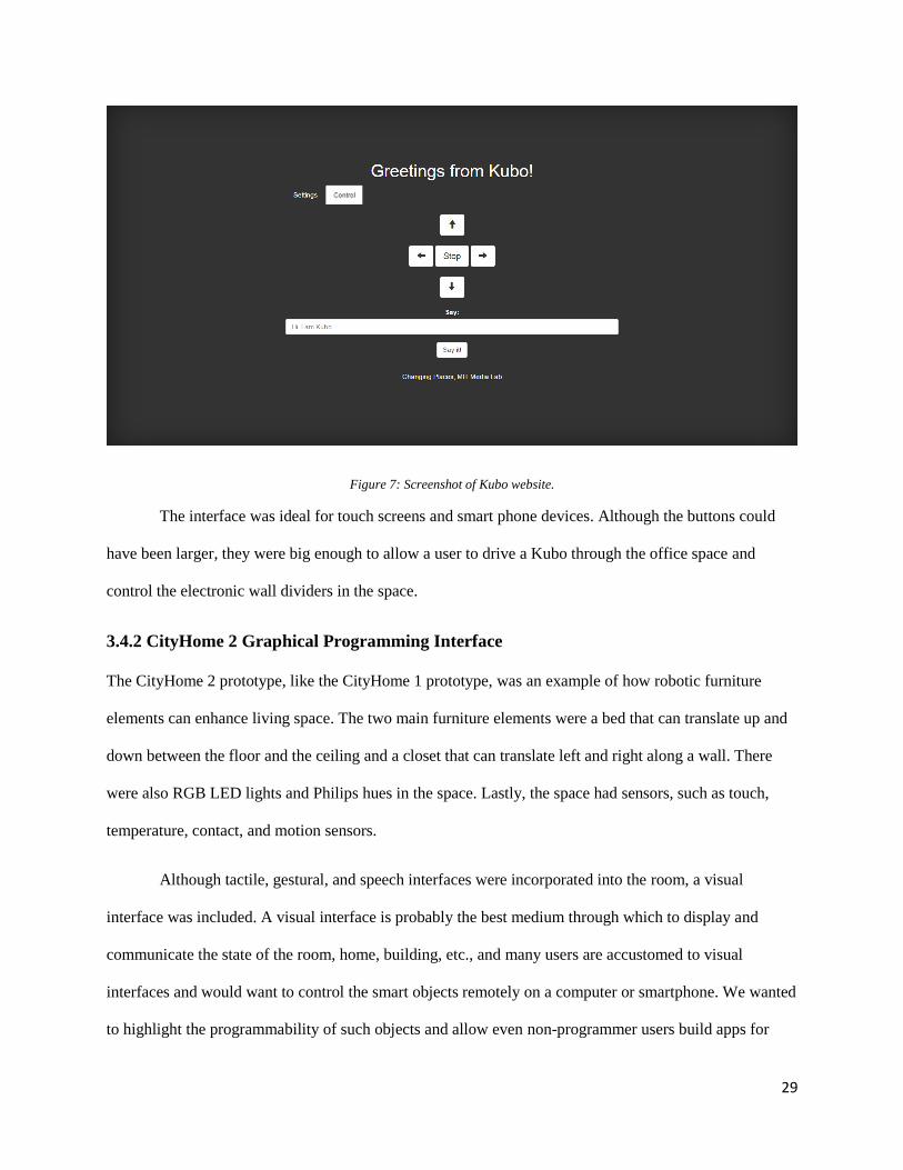
Figure 7: Screenshot of Kubo website.
The interface was ideal for touch screens and smart phone devices. Although the buttons could
have been larger, they were big enough to allow a user to drive a Kubo through the office space and
control the electronic wall dividers in the space.
3.4.2 CityHome 2 Graphical Programming Interface
The CityHome 2 prototype, like the CityHome 1 prototype, was an example of how robotic furniture
elements can enhance living space. The two main furniture elements were a bed that can translate up and
down between the floor and the ceiling and a closet that can translate left and right along a wall. There
were also RGB LED lights and Philips hues in the space. Lastly, the space had sensors, such as touch,
temperature, contact, and motion sensors.
Although tactile, gestural, and speech interfaces were incorporated into the room, a visual
interface was included. A visual interface is probably the best medium through which to display and
communicate the state of the room, home, building, etc., and many users are accustomed to visual
interfaces and would want to control the smart objects remotely on a computer or smartphone. We wanted
to highlight the programmability of such objects and allow even non-programmer users build apps for
30
their home. Therefore, we created a website to visualize the state of the smart objects in the room and a
website to control and program the smart objects.
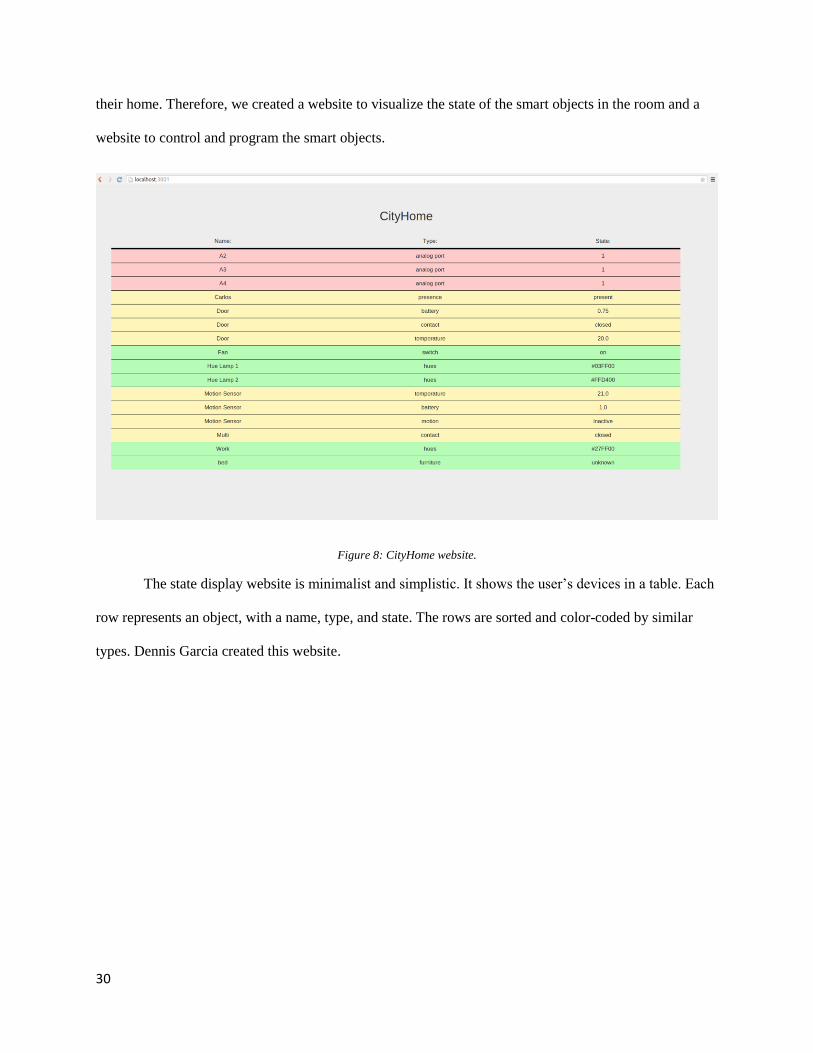
Figure 8: CityHome website.
The state display website is minimalist and simplistic. It shows the user’s devices in a table. Each
row represents an object, with a name, type, and state. The rows are sorted and color-coded by similar
types. Dennis Garcia created this website.
31
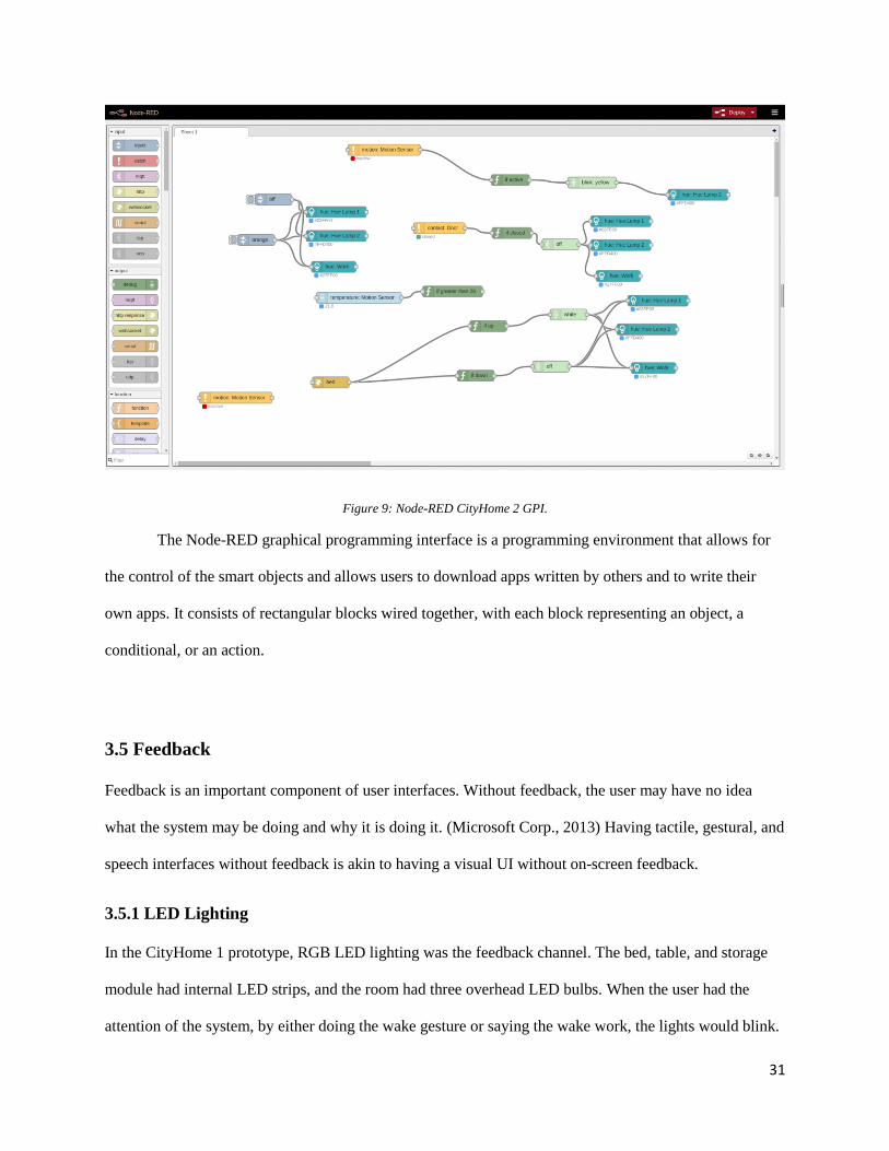
Figure 9: Node-RED CityHome 2 GPI.
The Node-RED graphical programming interface is a programming environment that allows for
the control of the smart objects and allows users to download apps written by others and to write their
own apps. It consists of rectangular blocks wired together, with each block representing an object, a
conditional, or an action.
3.5 Feedback
Feedback is an important component of user interfaces. Without feedback, the user may have no idea
what the system may be doing and why it is doing it. (Microsoft Corp., 2013) Having tactile, gestural, and
speech interfaces without feedback is akin to having a visual UI without on-screen feedback.
3.5.1 LED Lighting
In the CityHome 1 prototype, RGB LED lighting was the feedback channel. The bed, table, and storage
module had internal LED strips, and the room had three overhead LED bulbs. When the user had the
attention of the system, by either doing the wake gesture or saying the wake work, the lights would blink.
32
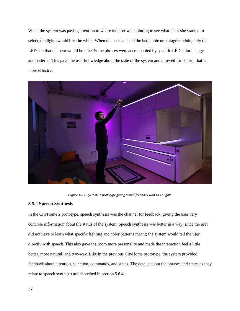
When the system was paying attention to where the user was pointing to see what he or she wanted to
select, the lights would breathe white. When the user selected the bed, table or storage module, only the
LEDs on that element would breathe. Some phrases were accompanied by specific LED color changes
and patterns. This gave the user knowledge about the state of the system and allowed for control that is
more effective.
Figure 10: CityHome 1 prototype giving visual feedback with LED lights.
3.5.2 Speech Synthesis
In the CityHome 2 prototype, speech synthesis was the channel for feedback, giving the user very
concrete information about the status of the system. Speech synthesis was better in a way, since the user
did not have to learn what specific lighting and color patterns meant; the system would tell the user
directly with speech. This also gave the room more personality and made the interaction feel a little
better, more natural, and two-way. Like in the previous CityHome prototype, the system provided
feedback about attention, selection, commands, and states. The details about the phrases and states as they
relate to speech synthesis are described in section 5.6.4.
33
We conducted user studies on the usability of these interfaces in the CityHome 2 environment.
The goal was to determine which of these interfaces were the most learnable, easy, efficient, and liked as
implemented in a smart home environment. The experiment, results, and conclusion are drawn out in
Chapter 6.

34
Chapter 4
4 Electronics and Microcontrollers
35
4.1 Purpose and Importance
Robotic furniture cannot exist without an integrated electronic brain that is in charge of managing all the
inputs and outputs of the furniture. An electronic brain is needed to read in all sensor inputs, such as
switches and FSRs, which may be used for control or data collection, and to control all outputs, such as
motors, actuators, and lights, which effectively enable and execute the transformations. A capable
microcontroller to add to the user experience and make the magic happen.
4.2 Execute, Manage, Perform
It is important to identify the different levels of control and electronics that exist in a robotic furniture
system and smart home environment, as well as the different types of electronic brains and capabilities
associated with each level. One system of classification is execute, manage, and perform, in increasing
order of complexity. (Herr & Duval)
4.2.1 Execute
Execute refers to the electronics and microcontrollers associated with the lowest level of control of
elements powered by electricity, like motors and actuators. Microcontrollers in this category usually have
clock speeds in the kHz range and memory in the kB range.
Motors, for example, require special electronics for optimal functioning. Electric motors begin to
spin when a voltage is applied across its terminal leads. Higher voltages (and currents) result in a
faster/higher cruising RPM (revolutions per minute). Reversing the voltage (flipping the leads) makes the
motor turn in the opposite direction. A simple battery or power supply, which supplies a constant voltage
and has a maximum current draw, is therefore insufficient to control an electric motor, since it cannot
control speed or direction. Special circuitry with transistors, MOSFETs, H-bridges, and/or a
microcontroller is needed.
36
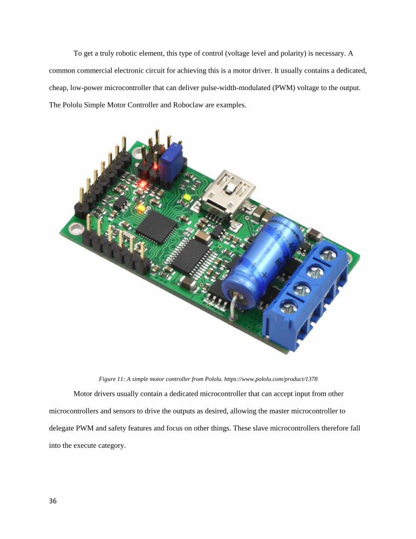
To get a truly robotic element, this type of control (voltage level and polarity) is necessary. A
common commercial electronic circuit for achieving this is a motor driver. It usually contains a dedicated,
cheap, low-power microcontroller that can deliver pulse-width-modulated (PWM) voltage to the output.
The Pololu Simple Motor Controller and Roboclaw are examples.
Figure 11: A simple motor controller from Pololu. https://www.pololu.com/product/1378
Motor drivers usually contain a dedicated microcontroller that can accept input from other
microcontrollers and sensors to drive the outputs as desired, allowing the master microcontroller to
delegate PWM and safety features and focus on other things. These slave microcontrollers therefore fall
into the execute category.
37
4.2.2 Manage
Manage refers to the electronics and microcontrollers involved with the middle level of control. These
electronics are in charge of managing an entire mechatronic system, like a robotic table. They usually
have to interact with components of the system, like slave microcontrollers and circuitry, to orchestrate
the final outputs of the system. They are also in charge of reading and responding to user input, like
switches and FSRs and must coordinate with the rest of the system to get the desired actions to happen
based on that input.
Microcontrollers in this category are at least as powerful as execute microcontrollers. They
usually have clock speeds in the MHz range and can have memory in the very low MB range. A system
can have a single managing microcontroller, or there can be a team of them. In many cases, commercial
products that have embedded electronics usually contain a managing microcontroller, and developers
make custom managing firmware for these products while the executing microcontroller firmware across
many products can be the same.
Often times, these microcontrollers have connection capabilities and can talk to other managing
microcontrollers, or to higher level computing units like microprocessors, processors, computers, and
servers. This communication usually involves sending and receiving commands. Some examples of
communication capabilities are serial, SPI, I2C, UDP, and TCP. These controllers may also be capable of
performing some complex actions, like executing some form of digital signal processing (DSP),
performing data analysis, and computing complex mathematical operations.
4.2.3 Perform
Perform refers to the electronics involved at the highest level of control. Microcontrollers are rarely in
this type of classification. More often, the lowest computing units in this classification are
microprocessors and single-board computers (SBC). Smartphones are examples of microprocessors
(processors are referred to as entire computing systems, rather than CPUs, in this paper). Even higher
38
level computing units, like processors (personal computers, for example) and servers (cloud) can take on
the perform role in mechatronic systems.
Processors in this category are usually more powerful than managing microcontrollers. They
usually have clock speeds in the GHz range and have memory at least in the MB range. They are tasked
with anything from directing a small collection of products, say in a home or factory, to managing an
entire fleet of managing microcontrollers over the Internet. Processors usually run high-level applications
since the low-level complexity is abstracted away in the execute and manage categories. Processors are
great for things like DSP and data management and analysis.
Processors allow programs to use a vast variety of freely available code, like the Robotic
Operating System (ROS). They allow the creation of large, complex programs, testing and debugging,
updating. They allow multiple applications to run simultaneously. Processors allow for rich application
development and user interaction, like the use of speech and gesture recognition.
Examples of interesting SBCs are the Intel Edison, Intel Galileo, UDOO, BeagleBone, and
Raspberry Pi. These were all considered for use in the CityHome and CityOffice prototypes.
4.3 Capabilities
The movements and transformations required by furniture mechatronic systems demand capable
microcontrollers. In particular, to get the minimum satisfying/viable experience, at least one dedicated
execute microcontroller and one manage microcontroller should be used. The execute microcontroller can
handle the power electronics and critical safety features while the manage microcontroller can expose
connectivity and manage the user interfacing and experience.
39
4.3.1 Inputs
Microcontrollers have input ports to which inputs and sensors can be hooked up to. Two types of inputs
are digital inputs and analog inputs.
Digital inputs are binary with two states, low and high. Low is usually ground, or 0 volts. High is
the voltage of the microcontroller, usually 3.3 or 5 volts. Digital input ports are driven to the state that the
sensor or input drives them to. The microcontroller then reads this as a Boolean value. Digital inputs are
simple to work with and can be either polled or used as interrupts. Interrupts are special in that whenever
the specified port is driven to the specified state, the microcontroller will halt its operations and run the
firmware code the programmer specified to be executed, resuming operations after the interrupt service
routine (ISR) is executed.
Analog inputs are continuous and range from ground (low) to power (high). Sensors that measure
continuous information, like potentiometers, thermistors, and FSRs, drive analog inputs. Because
microcontrollers operate in the digital binary realm, they cannot directly measure an intermediate voltage
value. They must use an analog to digital converter (ADC) which converts analog voltage values to
digital binary numbers, which the microcontroller (and programmer) can then work with.
4.3.2 Outputs
Microcontrollers have output ports to which outputs and circuitry can be hooked up to. Two types of
outputs are digital outputs and analog outputs.
Similar to digital inputs, digital outputs are binary with two states, low and high. The
microcontroller drives the port to either state, depending on the firmware. They are also simple to work
with and can drive many types of circuitry.
Similar to analog inputs, analog outputs are continuous and range from ground to power. Because
of microcontrollers’ digital limitation, they cannot drive their ports to an intermediate voltage level. They
can, however, use PWM to create an artificial voltage level. By switching between ground and power
40
quickly, many components and circuitry can be driven using analog output. Alternatively, one could use
digital to analog converters (DACs).
4.3.3 Connectivity
Magic and user experience would be extremely limited without connectivity. Connectivity allows the
microcontrollers to talk to components, microcontrollers, and processors. Many different forms of
connectivity exist.
Microcontrollers can employ many forms of wired connectivity. In the end, this boils down to
wires connected to the ports and the ports being driven in very specific, well-defined ways. Some
examples of wired communication protocols are serial, SPI, and I2C.
Microcontrollers equipped with wireless antennas can employ wireless connectivity. Although
locally it still boils down to port-level control, wireless connectivity really expands the flexibility and
versatility of the system (design and placement of the furniture is not constrained by wires) and allows for
truly bringing the furniture mechatronic systems into the Internet of Things (IoT). Some examples of
wireless communication protocols are Wi-Fi, Bluetooth (LE), ZigBee, and Z-Wave.
Connectivity is particularly important for truly expanding the power of the mechatronic systems.
Processors now have the ability to send commands to the microcontrollers and control the space. Many
rich apps can be written and deployed for these mechatronic systems and the home, including complicated
ones using gesture and speech recognition for user interfacing. The processor can also receive data from
the microcontrollers about sensors and events. This data can be logged and analyzed to draw patterns,
infer conclusions, make decisions, and enhance the user experience.
41
4.4 Requirements
With mechatronic systems, especially commercial ones that are going to be around people, there are
certain requirements that are essential for the microcontroller to have. In particular, the microcontroller
must implement safety features and be communicable and accessible to outside devices and applications.
4.4.1 Safety
Mechatronic systems must be safe. They should take all possible measures to ensure no harm comes to
people and animals. They should also try to minimize any possible property damage. Safety features take
the form of mechanics, electronics, firmware, and software. In general, the lower the level in which the
safety features are implemented, the better and safer the system is. Ideally, the system should be able to
recover from failure by itself or with minimal user interaction, but having the system shutdown and wait
for expert repairs is another safety feature.
Microcontrollers should continuously monitor all connected components for signs of errors,
distress, and failures. Upon detection, the microcontroller should attempt to correct them and/or alert the
user. If the microcontroller or user is unable to fix the problem, the microcontroller should make the
system fail in the safest way possible and keep the system in that state until expert help arrives.
The microcontroller should prioritize local control over remote control. If there is a conflict
between control sensors and remote commands from other manage microcontrollers or perform
processors, the remote commands should be ignored, and the microcontroller should operate according to
the control sensors. Likewise, the microcontroller should ignore any command that could jeopardize
safety. Lastly, the microcontroller (and processor combination) should implement firmware and
communication safety features necessary to thwart malicious hackers. This is especially important, as
these are personal elements within the home that only authorized users should have control over.
42
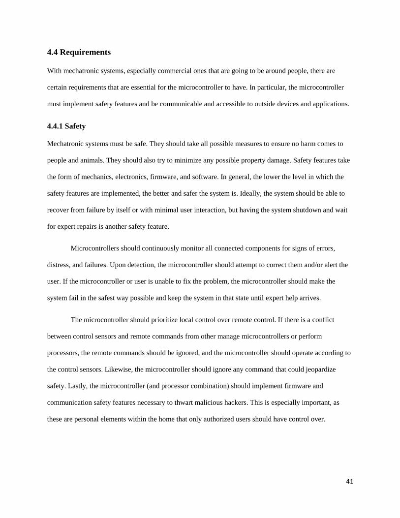
4.5 CityHome 1
The CityHome 1 prototype consisted of a 200 sq. ft. apartment room with RGB LED lights, electronic
shades/blinds, a pico projector, and a big storage module housing a bed, table, and LED strips. A more
thorough description of the elements of the prototype can be found in section 5.4.3.
Figure 12: CityHome 1 prototype.
All these objects needed the right circuitry and logic to power and control them. The circuitry
itself was rather simplistic and consisted mostly of a few resistors, capacitors, and transistors. The
electronic brains were Arduino Megas.
43
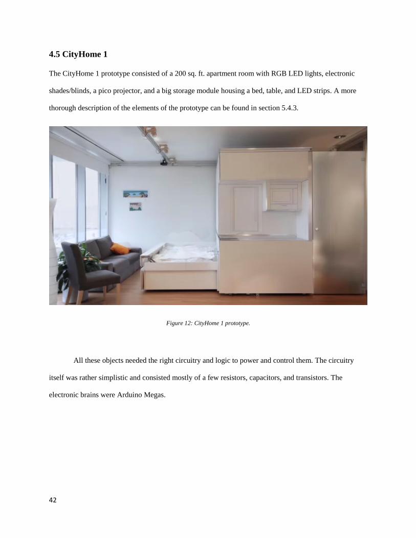
Figure 13: Arduino Mega. http://www.arduino.cc/en/Main/arduinoBoardMega
The Arduino Megas contained custom firmware developed by the author, Daniel Goodman, and
Matthew Daiter. The microcontrollers’ main job was to interpret commands from the central computer
and control the objects accordingly. The microcontrollers used wired USB connections to communicate
with the central computer.
The programming paradigm for the message interpretation and control involved nesting and state
machines. The first byte sent to a microcontroller would usually reference the resource/object the
computer wished to manipulate. The second and sometimes third byte and fourth byte would usually
reference the desired action or actions for the object to take. In this way, the microcontroller behaved as a
state machine whose actions and transitions depended on the bytes as they were received.
44
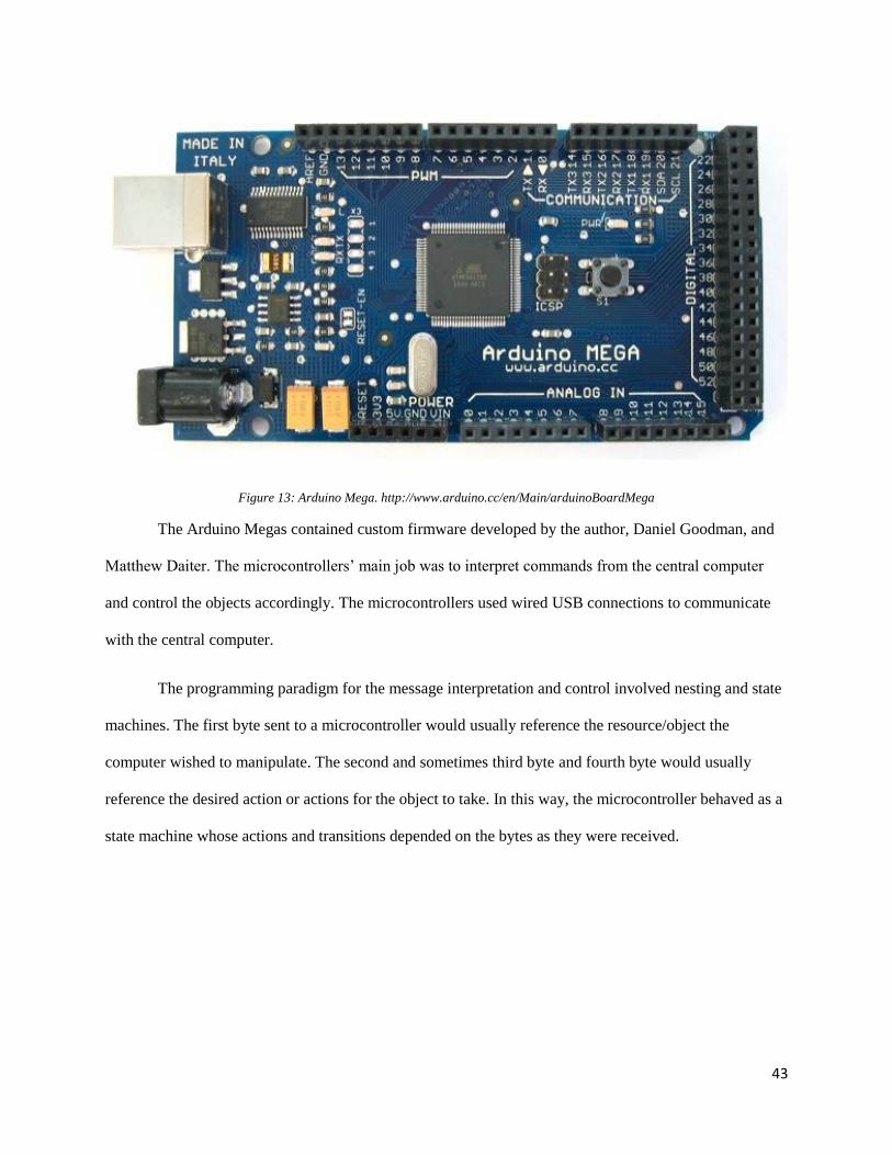
4.6 CityOffice
The CityOffice prototype consisted of a small office space with blinds (representing walls) that could
partition the space and three mobile robotic desks called Kubos that could move within the space and
transform between cubes, sitting desks, and standing desks.
Figure 14: CityOffice prototype space.
The three main components of the electronic systems were the Pololu simple motor controllers,
two Arduino Megas, and two Spark Core microcontrollers.
4.6.1 Motor Drivers
As described in section 4.2.1, a motor driver is an electronic system that can convert the constant voltage
supplied by a battery or power supply into a variable voltage that can control the speed and direction of a
motor.
Pololu simple motor controllers were connected to the motors that move the wheels of the Kubos,
the motors that change the height of the desk surfaces, the motors that deploy the desk flaps to change the
area of the desk surfaces, and the Kubo screen motors. They were controlled by a computer and an
Arduino Mega on one Kubo and a Spark Core (described in section 4.6.3) on the other Kubo.
45
The Pololu simple motor controllers have multiple methods of communication. They can
communicate with computers via a USB connection, allowing computers to monitor the entire system
state, set up the driver for control by a microcontroller, or control the driver directly. They can
communicate with microcontrollers over serial or Servo/RC. Servo/RC is a special form of PWM. The
microcontroller protocol used in the CityOffice prototype was Servo/RC due to its simplicity.
4.6.2 Height Control
The Kubos’ height could be adjusted using electric motorized desk legs. The legs were salvaged from
commercially available desks, with the wires rerouted from a proprietary controller to our
microcontrollers.
The interesting and challenging part about controlling the legs is that they need to move up and
down in sync. If the legs do not move at the same speed, they could become uneven and break the desk or
at least present a tilted surface that is uncomfortable to work on or unusable. Applying the same speed
command to the drivers is not enough, since same or very similar voltages on the motors might result in
slightly different speeds due to differences in the motors and drivers, among other things. The
microcontroller therefore needs knowledge about how many revolutions each motor has made to adjust
speeds if one is faster than the other is.
A proven way to keep the legs balanced is using PID control. PID stands for proportional,
integral, derivative. It is a way to control error in many applications; error in this case is the difference in
height between the legs.
PID requires reliable information about the height of each leg or the number of revolutions each
motor has made. One way to measure this is using encoders. Encoders are motor sensors that measure
how many revolutions (or parts of revolutions) the motor has spun. The commercially available leg
motors used in the CityOffice prototype do have built-in encoders. Unfortunately, they proved very
46
unreliable, to the point that we could not use PID control. The reason for their unreliability was not
determined. It was also unclear how the proprietary controller used the encoders.
In lieu of PID control, open-loop timing based control was used. On startup, the legs would
slowly lower until they reached the very bottom (there were limit switches at the bottom). This way, the
microcontroller knew that the legs were at the bottom and level. There were three possible states/positions
for the legs: bottom, middle/sitting, and high/standing. When transitioning to sitting and standing modes,
the microcontroller would command the motors in the appropriate direction for a set amount of time
determined empirically to approximately reach the set heights. The error turned out to be tolerable,
although it would compound if the states would switch between sitting and standing often without going
to the bottom. In fact, the error was greater in that the height for sitting and standing would vary slightly
upon every transition, especially as the battery discharged, as opposed to the error between the heights of
the two legs. A netbook (described in section 5.5.1) and an Arduino Mega controlled the first Kubo, while
a Spark Core operated the second Kubo.
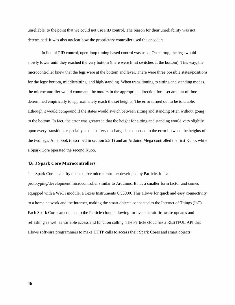
4.6.3 Spark Core Microcontrollers
The Spark Core is a nifty open source microcontroller developed by Particle. It is a
prototyping/development microcontroller similar to Arduinos. It has a smaller form factor and comes
equipped with a Wi-Fi module, a Texas Instruments CC3000. This allows for quick and easy connectivity
to a home network and the Internet, making the smart objects connected to the Internet of Things (IoT).
Each Spark Core can connect to the Particle cloud, allowing for over-the-air firmware updates and
reflashing as well as variable access and function calling. The Particle cloud has a RESTFUL API that
allows software programmers to make HTTP calls to access their Spark Cores and smart objects.
47
Figure 15: Spark Core microcontroller, Wi-Fi included. https://www.particle.io/prototype
4.6.4 Limitations
The main problems that arose in this prototype are wireless connectivity issues and latency. Commands
have to hop through many hoops; the user device sends commands to a CityHome computer, which sends
commands to the Spark cloud, which sends commands to the Spark Cores. This makes it easy for the
packets to be slowed down and even lost in transit, something undesirable in robotic applications such as
this. Indeed, sometimes commands would take seconds to execute. Amplifying the problem, users would
repeat commands when nothing happened, and these commands would be buffered and then execute in
succession, which would not produce the intended behavior.
48
Another problem with regards to connectivity involves the mobile nature of the Kubos. When
navigating the building as opposed to a single room, the computer and microcontrollers would jump
between wireless routers, temporarily losing connectivity and being reassigned IP address. This required
the system to be reset and reconfigured to the new addresses, something that cannot be tolerated on a
regular basis.
Mitigating these problems was explored in the following CityHome 2 prototype.
4.7 CityHome 2
The CityHome 2 prototype consists of a 300 sq. ft. apartment with multiple smart objects. It has a
cantilevered bed connected to two vertical lead screws that can move down onto the floor for sleeping and
up into the ceiling when not needed. It has a closet with wheels connected to a horizontal lead screw
along the floor and wall that can translate left and right to change the space of the room. It has three
Philips Hue LED lights and LED light strips embedded in the bed. It also has some smart objects from
SmartThings.

49
Figure 16: CityHome 2 prototype.
The main electronic brains of the room were Spark Core microcontrollers. The firmware for the
Spark Cores was more complicated than that of the previous prototypes and was written by the author and
Eric Ponce.
4.7.1 Control Loop
The Spark Cores’ main job was to control the bed and closet motors. There was a single motor on the
closet that was controlled again by a Pololu simple motor controller driven by Servo/RC control by a
Spark Core. There were two motors on the bed, and synchronous movement was crucial. Because of this,
a Roboclaw motor driver was chosen. It can control two motors independently and take input from their
encoders to keep them level. The Roboclaw took serial commands from another Spark Core.
The Spark Cores are also in both cases connected to FSRs. When a user pushes on the handle
with the embedded FSRs, signifying the desire to move the furniture in that direction, the Spark Core
registers that change in pressure/force and commands the motor driver to take the appropriate actions.
Input from the FSRs take precedence over any remote command the Spark Core may receive.
50
4.7.2 Communication
On system startup, the relevant perform microprocessor/processor has no way of knowing what
microcontrollers are out there, what resources they have, and how to access them (unless this is hard-
coded by the programmer, which is not scalable). The processor also needs to know what transfer
protocol to use to talk to the microcontrollers.
The two main Internet transfer protocols are the Transport Control Protocol (TCP) and the User
Datagram Protocol (UDP). TCP is a streaming and reliable protocol. The two parties open a socket
connection with each other, and communication is reliable and in-order with acknowledgement packets
sent liberally. UDP is a connectionless and unreliable protocol. One party simply sends a message to the
specified address and hopes the other party will receive it. As such, it is faster, simpler, and requires less
overhead. Because of the simplicity of UDP, we are using microcontrollers (in fact, a protocol called
Constrained Application Protocol has been developed as a reliable way to use UDP in low power
applications), we are using a local network, and the event-based nature of the system, UDP was chosen as
the communication protocol initially. Unfortunately, the Spark Core has known issues with UDP, and
although we believed they would not affect system performance at first, we found that this was not the
case over the course of the semester and have switched to TCP. We have found more success with TCP.
Next, the processor needs a way to know the IP addresses of the microcontrollers. Although some
methods and protocols for this exist, one of the simplest methods is multicast. Multicast is a way to send
UDP packets to multiple parties. A party can request to join a multicast group, associated with a local IP
address. When a packet is sent to this IP address, all parties that have requested to join the group receive
the packet. In this way, the processor can join a group, and the microcontrollers can send multicast
packets to this group. This should be done when the microcontroller boots up, and can be done at regular
intervals if desired.
The structure of the data to be exchanged needs to be determined. The structure chosen was
JavaScript Object Notation (JSON). JSON is a popular web and computer data structure for representing
51
objects and hierarchies, which makes it well suited to represent the resources available on the
microcontroller. JSON is easy to work with in many programming languages; many capable libraries for
this have been written. The Spark Cores can also handle JSON, but JSON is considerably heavyweight
for microcontrollers, and, especially since flash memory is limited on the Spark Core, it quickly became
hard to manage. Because of this, although JSON remained the primary representation for API purposes on
the software side, the data and access structuring of the microcontroller is to that similar of the nested
state machine representation of the previous CityHome 1 prototype. The first byte of the packet references
the resource the processor wishes to access. Currently, the programmer/processor must know the
mapping, but one could develop a way to avoid this. The second byte references the desired action in
most cases. The third byte is reserved in some cases and references the desired action in the other cases.
Again, the programmer/processor must know this.
Of importance is a way for the microcontroller to transmit its state and to report events to any
interested parties. There are multiple ways to do this, but this was not implemented at the time of this
writing.
4.7.3 Resource Representation
How the microcontroller represents and exposes its resources is important. Resources refers to the inputs
and outputs of the microcontrollers.
We divided the resources into two categories. The first category is high-level and deals more with
particular objects. Within this category, two subcategories exist. The first is that of sensors. Sensors are
inputs, like FSRs. The microcontroller may have an involved way of obtaining the sensor data. While the
data at the low level may be voltage levels or packets, the data at the high level is the actual information
the sensor was intended to get, like temperature or force. This high-level data is associated with the
resource, acted upon, and transmitted. The second subcategory is that of actuators/appliances. They are
outputs, like motor drivers. The microcontroller again may have an involved way of driving the output,
52
which may involve packets or port writes at the low level. At the high level, though, the command,
intended action, or current state of the output is the one associated with the resource.
The second category is low-level and deals more with particular ports on the microcontroller.
Within this category, the two subcategories are analog ports and digital ports. This category was intended
to allow the processor to drive ports on the microcontroller directly. This is acceptable when the input or
output connected to the microcontroller at those ports does not require quick communication or fine-
grained control, or when a new sensor or actuator is added and the programmer cannot or does not want to
change the firmware and instead program the functionality on the software side. Simple LEDs, or sensors
whose data is not used by the microcontroller, work well in this category. Arduino’s Firmata and
Particle’s Tinker are examples of this type of resource representation and control.
4.7.4 Limitations
Although efforts were made to mitigate the limitations experienced in the previous CityOffice prototype
with Spark Cores (we programmed direct TCP/UDP access to the Spark Cores as opposed to going
through the Spark Cloud), we found that Spark Cores are still under development and do not have
sufficiently robust connectivity. Issues included UDP bugs and streaming TCP limitations. Nonetheless,
we were able to achieve sufficiently good communication capabilities.
Additionally, the current Roboclaw controller which drives the bed cannot do the PID control we
want. The bed actuators can only realign themselves after they stop, not while the bed is moving. Future
work will involve implementing PID control directly on the Spark Core.

53
Chapter 5
5 Software
54
5.1 Purpose and Importance
Although robotic furniture can exist without software, software opens up the possibilities for all sorts of
applications, from rich user interfaces to data mining and activity recognition to health and affective
computing. Software and a capable processor(s)/computer(s) are needed to really take the robotic
furniture to the next level and enhance the user experience and provide the magic.
5.2 Microcontroller vs. Microprocessor vs. Processor
It is important to make the distinction between microcontrollers, microprocessors, and processors,
especially in the realm of smart home computing. Microcontrollers are discussed at length in sections 4.1-
4.4. In summary, they are great for interfacing with electronics and controlling the physical environment,
but they are not so great when it comes to speed and memory. They lack the volatile memory, non-
volatile memory, and processing speed that processors have by orders of magnitude more. They do not
have automatic memory management and cannot run an operating system. They are better for particular
tasks, and not so good for managing entire systems, working with a lot of data, and running applications.
5.2.1 Microprocessor
We here make a distinction between microprocessors and processors, one which does not depend on
physical size nor refers to the computing unit by itself.
We classify a microprocessor as a computing unit with usually less than 1 GHz processing speed
and less than 1 GB of RAM. Microprocessor computers usually have small form factors; examples
include smartphones, Raspberry Pi, UDOO, and BeagleBone. Microprocessors have memory
management and usually run free or open source operating systems (Linux). Although microprocessors
usually have limited peripheral connectivity, they also usually have ports, just like microcontrollers.
Microprocessors could therefore replace microcontrollers in some applications. They, however, are
usually more expensive and bigger than microcontrollers are. Because they run operating systems and
55
have to deal with a lot more, they may also be less robust than microcontrollers for control operations.
Nevertheless, microprocessors are receiving attention, especially for IoT applications. Although
microprocessors were considered for potential use in all three prototypes, it was always decided to use a
microcontroller and processor combination instead.
5.2.2 Processor
We classify a processor as anything more powerful than a microprocessor: greater than 1Gz processing
speed and greater than 1 GB of RAM. Processors usually have big form factors, like laptops and tablets,
desktop computers, and servers. Although they usually have more peripheral connectivity than
microprocessors, they usually do not have ports with which to interface electronics. Processors cannot
replace microcontrollers for physical control operations and are usually much bigger and more expensive
than microprocessors. Because processors can interface with microcontrollers well, using a
microcontroller and processor combination brings the best of both worlds. All three prototypes used this
combination.
5.3 Capabilities
The applications for and data from the smart home and furniture mechatronic systems demand capable
processors. In particular, at least one processor, whether local or remote, should be used. The processors
will need adequate communication capabilities and data management.
5.3.1 Communication
Although there are many communication peripherals and protocols, the ones used in the three prototypes,
and important ones in general, are wired and Wi-Fi peripherals using serial and Internet protocols.
The processor should be able to communicate with the microcontroller over a wired serial
connection. Most processors do indeed have this capability. The most popular peripherals are Universal
Serial Bus (USB) and RS-232 connections. At the low level, the microcontroller and processor use an
56
agreed upon baud rate, or speed at which bits are exchanged, and drive line voltages high and low in
succession to transmit data. Serial communication is simple, fast, and reliable. The limiting factor is
usually the microcontroller and how fast it can read and write to the line and run the rest of the firmware.
Unfortunately, this forces a direct wire between the two, which is sometimes inconvenient or impossible,
especially in remote applications or applications with moving parts. Wired serial connections were used
in the CityHome 1 prototype and CityOffice prototype.
The processor should be able to communicate with the microcontroller wirelessly over TCP or
UDP. TCP and UDP are discussed at length in section 4.7.2. This was the method of communication in
the CityHome 2 prototype. TCP/UDP can be used internally between programs on the same machine,
locally between machines on the same local network, and remotely over the Internet.
Finally, the processor should be capable of communicating to servers, computers, and/or
microcontrollers over the Hypertext Transport Protocol (HTTP). This is one of the most popular Internet
communication protocols. While it has a good amount of overhead, it is nonetheless simple, provides a
way to structure data for transport, and defines rules for interaction. Libraries for HTTP exist for many
programming languages. The CityOffice prototype controls were exposed over HTTP, and commands
were sent to the Spark Cores by sending HTTP commands to Spark loud servers, which then sent CoAP
commands to the Spark Cores.
5.3.2 Data Management
Data management is important in these applications. One must decide how data, objects, resources, and
events are represented, structured, organized, stored, and read. Well-defined data structuring for the
development of APIs is important, as different machines and applications need to be able to parse the
data. Two popular ways of structuring data is the Extensible Markup Language (XML) and JavaScript
Object Notation (JSON). JSON was chosen in the CityHome 2 prototype and is discussed at length in
section 4.7.2.
57
Resource representation is important; the processor must understand how resources the
microcontroller represents resources in order to parse data and access and command those resources.
Resource representation was not well developed in the CityHome 1 and CityOffice prototypes, as
microcontroller and cloud data management was not implemented, event-driven programming was not
developed, and there was no need for it. Resource representation was explored in the CityHome 2
prototype and is discussed in section 4.7.3.
5.4 CityHome 1
5.4.1 Processor Specs
The perform processor, or central computer, chosen for this prototype was a custom-built computer built
by Matthew Daiter. It was very powerful; it had 12 GB of RAM, 113 GB of SSD memory, and 8
processing cores with 3.4 GHz processing speed. It ran Windows 7 and was more than capable of
managing the gestural and speech inputs of the room with the Microsoft Kinect and commanding the
microcontrollers.
5.4.2 Software Choice
Because the prototype had a Microsoft Kinect, the easiest and most pain-free software choice was using
C# for the programming language choice and Microsoft Visual Studio as the Integrated Development
Environment (IDE). This allowed us to download, install, and use the Microsoft Kinect SDK, which
allowed for the use of the connected Kinect. A serial communication library was used for the control of
all the connected microcontrollers. The Microsoft Speech SDK was used for speech recognition.
5.4.3 Elements
The CityHome 1 prototype had a considerable amount of smart elements. It had a bed, table, storage
module, LED lighting, blinds, and a pico projector.
58
The storage module was a big modular structure that housed the bed, table, and LED strips. It also
housed much of the electronics and the central computer that controlled the home. It had compartments
that would have allowed for additions, whether they be for storage (clothes, for example), a microwave, a
sink, and a stovetop. The module had wheels and electric motors, allowing it to translate horizontally
along a track in the room. The module could move to one extreme, maximizing bathroom space and to
another extreme, maximizing bedroom, dining room, living room, or kitchen area.
The bed and table also had motorized wheels and embedded LED strips. They could translate in
and out of the storage module, converting the space into a bedroom or dining room or working area upon
request. The bed, table, and storage module had FSRs on them, each detecting a force in a direction,
which would allow the user to effortlessly push or pull each element in each direction. These elements
were also controllable with speech and gestures.
The space had LED RGB lighting, filling the space with colored light and opening up
opportunities for visual feedback and setting the mood and affective computing. The lighting consisted of
three strips, for each of the bed, table, and module, and three overhead bulbs. The lights were connected
to a circuit with a power supply, resistors, transistors, and microcontroller to control the intensity of each
color channel. The lights could be set via speech and gesture control and were used by the system to give
feedback about its state, described in section 3.5.1.
The room had motorized blinds that could be controlled by gestures and speech to change the
natural lighting of the room and alter privacy.
Finally, the room had a pico projector hanging from the ceiling. It had two pivoting servos,
allowing it to rotate and tilt. Together with an autofocusing setup, it could project on different surfaces in
the room, whether it be walls, floor, storage module, or table. It projected on four predefined surfaces, and
key-stoning software corrected for the different projection angle distortions.
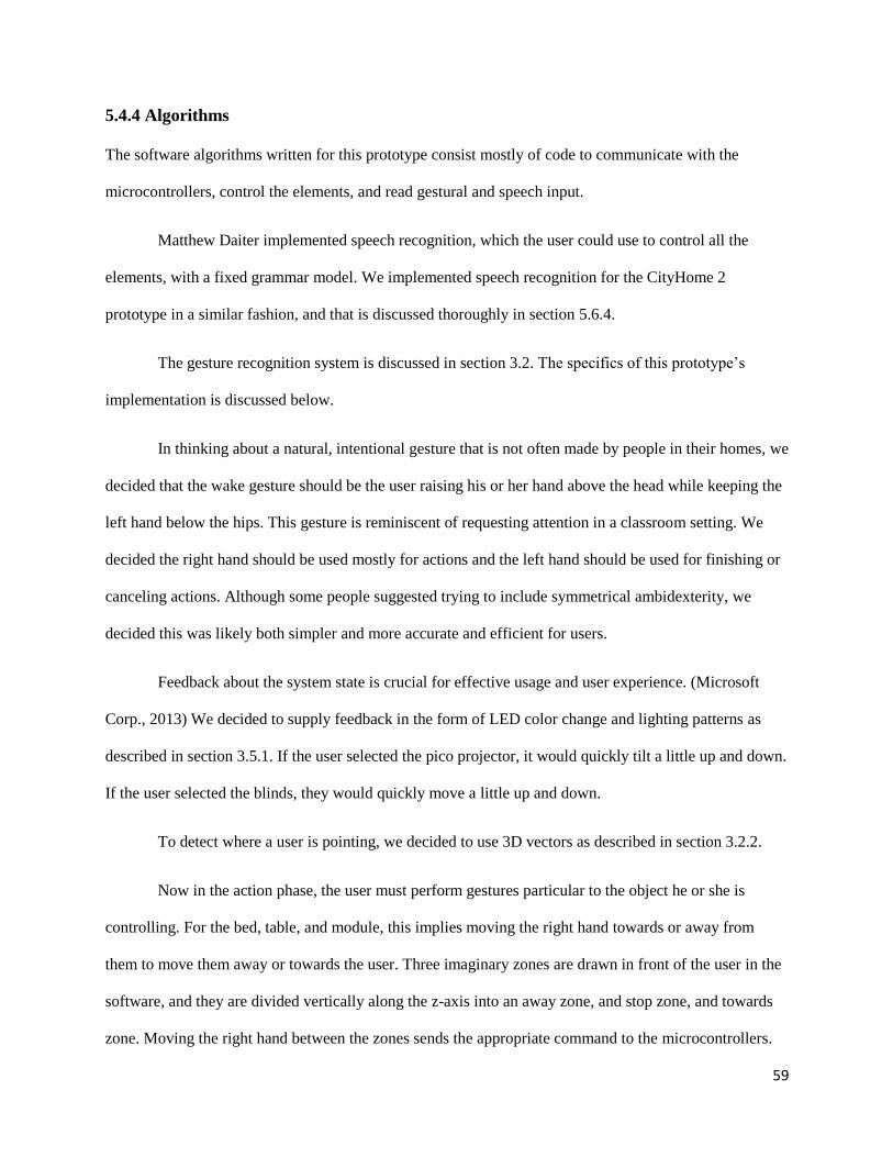
59
5.4.4 Algorithms
The software algorithms written for this prototype consist mostly of code to communicate with the
microcontrollers, control the elements, and read gestural and speech input.
Matthew Daiter implemented speech recognition, which the user could use to control all the
elements, with a fixed grammar model. We implemented speech recognition for the CityHome 2
prototype in a similar fashion, and that is discussed thoroughly in section 5.6.4.
The gesture recognition system is discussed in section 3.2. The specifics of this prototype’s
implementation is discussed below.
In thinking about a natural, intentional gesture that is not often made by people in their homes, we
decided that the wake gesture should be the user raising his or her hand above the head while keeping the
left hand below the hips. This gesture is reminiscent of requesting attention in a classroom setting. We
decided the right hand should be used mostly for actions and the left hand should be used for finishing or
canceling actions. Although some people suggested trying to include symmetrical ambidexterity, we
decided this was likely both simpler and more accurate and efficient for users.
Feedback about the system state is crucial for effective usage and user experience. (Microsoft
Corp., 2013) We decided to supply feedback in the form of LED color change and lighting patterns as
described in section 3.5.1. If the user selected the pico projector, it would quickly tilt a little up and down.
If the user selected the blinds, they would quickly move a little up and down.
To detect where a user is pointing, we decided to use 3D vectors as described in section 3.2.2.
Now in the action phase, the user must perform gestures particular to the object he or she is
controlling. For the bed, table, and module, this implies moving the right hand towards or away from
them to move them away or towards the user. Three imaginary zones are drawn in front of the user in the
software, and they are divided vertically along the z-axis into an away zone, and stop zone, and towards
zone. Moving the right hand between the zones sends the appropriate command to the microcontrollers.
60
To end the gesture, the user must raise the left hand to the right hand’s height (in the y-axis). This will
stop the movement and put the system back into selection mode.
Controlling the lights implies moving the right hand through an imaginary rectangular area in
front of the user. The X coordinate of the hand in this rectangle determines the color, while the Y
coordinate determines the intensity. This way, the entire color capabilities of the RGB LED lights are
exposed. The commands are sent continuously to the microcontrollers, and the lights change continuously
as the user moves the right hand through the rectangle. Raising the left hand to the right hand’s height will
set the lights to the color and intensity the right hand was at in that frame. This will reset the system back
into selection mode.
5.4.5 Limitations
Most of the issues encountered involved the speech and gesture recognition systems. The limitations of
these systems are discussed in sections 6.3.3 and 6.3.4.
5.5 CityOffice
5.5.1 Processor Specs
The perform processor chosen for this prototype was an Acer C720 Chromebook. It had 2 GB of RAM,
16 GB of SSD memory, and dual processing cores with 1.4 GHz processing speed. It was formatted and
installed with Ubuntu. It was chosen for its small form factor and great battery life, making it well suited
to process commands over the Internet and travel on and control the Kubo.
5.5.2 Software Choice
Because there were no constraints on the system like in the previous CityHome 1 prototype, there was
more freedom to choose the programming language. Because of the robotic nature of the prototypes, we
decided to explore using the Robot Operating System (ROS). ROS is a great middleware with easy
61
integration of robotics software written by universities, companies, and individuals and a great platform
for message passing and communication between programs running on same and different machines.
ROS is compatible with C++ and Python and has a library that supports JavaScript. Because
Python is simple and readable and because no fine-grained or time-sensitive control was necessary, it was
chosen as the primary programming language. The main goal of the software was to manage the control
of the Kubos’ wheels, legs, flaps, and screen and the room dividers.
To control the Kubos and room dividers, we developed a website, written in HTML and
JavaScript with the meteor platform. All this is discussed in section 5.5.4.
5.5.3 Elements
The CityOffice prototype’s main object was the Kubo, the mobile robotic desk. The Kubo’s main
elements are the wheels, legs, screen, and flaps. In addition, the room had screens representing room
dividers that could partition the space on demand.
The motorized wheels allow the Kubo to navigate the space. There are two wheels on two axes on
the Kubos, for a total of four wheels. Pololu simple motor controllers differentially drive them. On one
Kubo, the motor drivers are directly connected to the computer over a USB connection. On the other, they
are connected to Spark Cores over Servo/RC lines. The wheels can move in the same or different
directions at same or different speeds, giving the Kubo a range of motion limited by the mechanical
configuration of the Kubo base and by the error between the drivers, motors, and wheels. Further details
about wheel control can be found in section 4.6.1.
The legs allow the Kubo to change height. The Kubo can alternate between a small cube, a sitting
desk, and a standing desk. Details about height control can be found in section 4.6.2.
The screens on the Kubos are intended to serve multiple purposes. While only panes in the
prototypes, the screens could function to increase privacy and allow for a “cubicle” on demand. They
could also house a computer screen. The flaps on the Kubos can be deployed to increase effective desk
62
area. The screens are connected to small, commercial translation modules, and the flaps are connected to
small, commercial pistons/actuators that take in simple high-voltage binary commands to control
direction of movement.
The room dividers are screens rolled over the axis of motors. The motors are connected to
commercial drivers. The drivers are connected to an Arduino Mega that can toggle each screen to move
up, down, and stop with simple binary digital writes. The Arduino Mega receives USB serial commands
from an Acer C720 computer.
5.5.4 Algorithms
The software algorithms written for this prototype consist of taking control input from the user remotely
and affecting the appropriate elements.
The UI consists of a website, shown in section 3.4.1. The website was made using Meteor and
was hosted on the free Meteor servers. It was written in HTML, CSS, and JavaScript and used Twitter
Bootstrap, jQuery, and the JavaScript ROS package. Upon loading the website in a client web browser,
the client establishes a WebSocket connection with the host ROS computer. The control buttons on the
website all had button click event listeners on them. Clicking on them would publish a ROS message that
would be sent to the host ROS computer and processed accordingly. For the first iteration Kubo, the
website had five buttons a page: forward, back, left, right, and stop. The host ROS computer, which was
housed inside the Kubo, would receive these messages and send the appropriate commands to the
connected motor drivers. Because of the design of this Kubo base, the Kubo could not rotate on its axis
(much like a car), and using the left and right buttons would result in a forward left and forward right turn
respectively. Clicking on the same movement button multiple times, up to three times, would increase the
speed. On another page, three buttons corresponded to the height of the desk: undeployed, sitting, and
standing. Two buttons corresponded to the screen: deployed or undeployed.
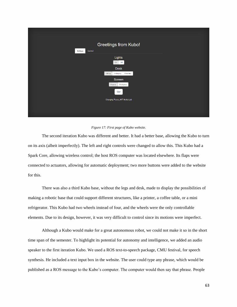
63
Figure 17: First page of Kubo website.
The second iteration Kubo was different and better. It had a better base, allowing the Kubo to turn
on its axis (albeit imperfectly). The left and right controls were changed to allow this. This Kubo had a
Spark Core, allowing wireless control; the host ROS computer was located elsewhere. Its flaps were
connected to actuators, allowing for automatic deployment; two more buttons were added to the website
for this.
There was also a third Kubo base, without the legs and desk, made to display the possibilities of
making a robotic base that could support different structures, like a printer, a coffee table, or a mini
refrigerator. This Kubo had two wheels instead of four, and the wheels were the only controllable
elements. Due to its design, however, it was very difficult to control since its motions were imperfect.
Although a Kubo would make for a great autonomous robot, we could not make it so in the short
time span of the semester. To highlight its potential for autonomy and intelligence, we added an audio
speaker to the first iteration Kubo. We used a ROS text-to-speech package, CMU festival, for speech
synthesis. He included a text input box in the website. The user could type any phrase, which would be
published as a ROS message to the Kubo’s computer. The computer would then say that phrase. People
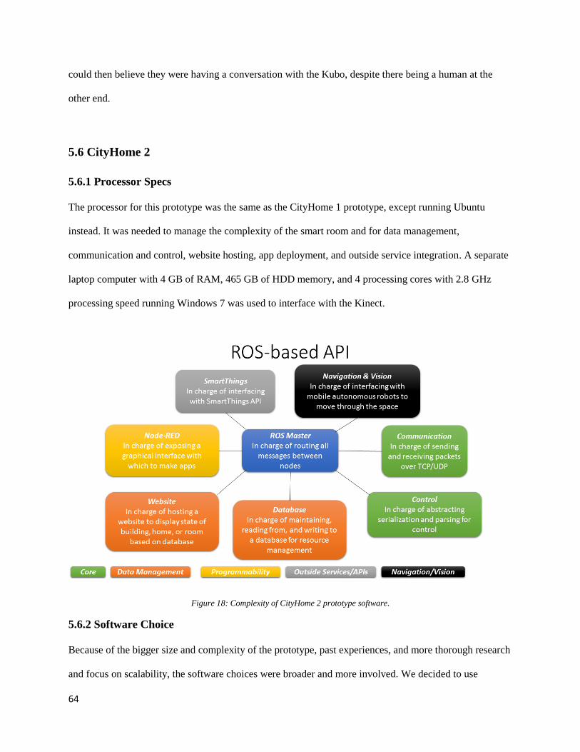
64
could then believe they were having a conversation with the Kubo, despite there being a human at the
other end.
5.6 CityHome 2
5.6.1 Processor Specs
The processor for this prototype was the same as the CityHome 1 prototype, except running Ubuntu
instead. It was needed to manage the complexity of the smart room and for data management,
communication and control, website hosting, app deployment, and outside service integration. A separate
laptop computer with 4 GB of RAM, 465 GB of HDD memory, and 4 processing cores with 2.8 GHz
processing speed running Windows 7 was used to interface with the Kinect.
Figure 18: Complexity of CityHome 2 prototype software.
5.6.2 Software Choice
Because of the bigger size and complexity of the prototype, past experiences, and more thorough research
and focus on scalability, the software choices were broader and more involved. We decided to use
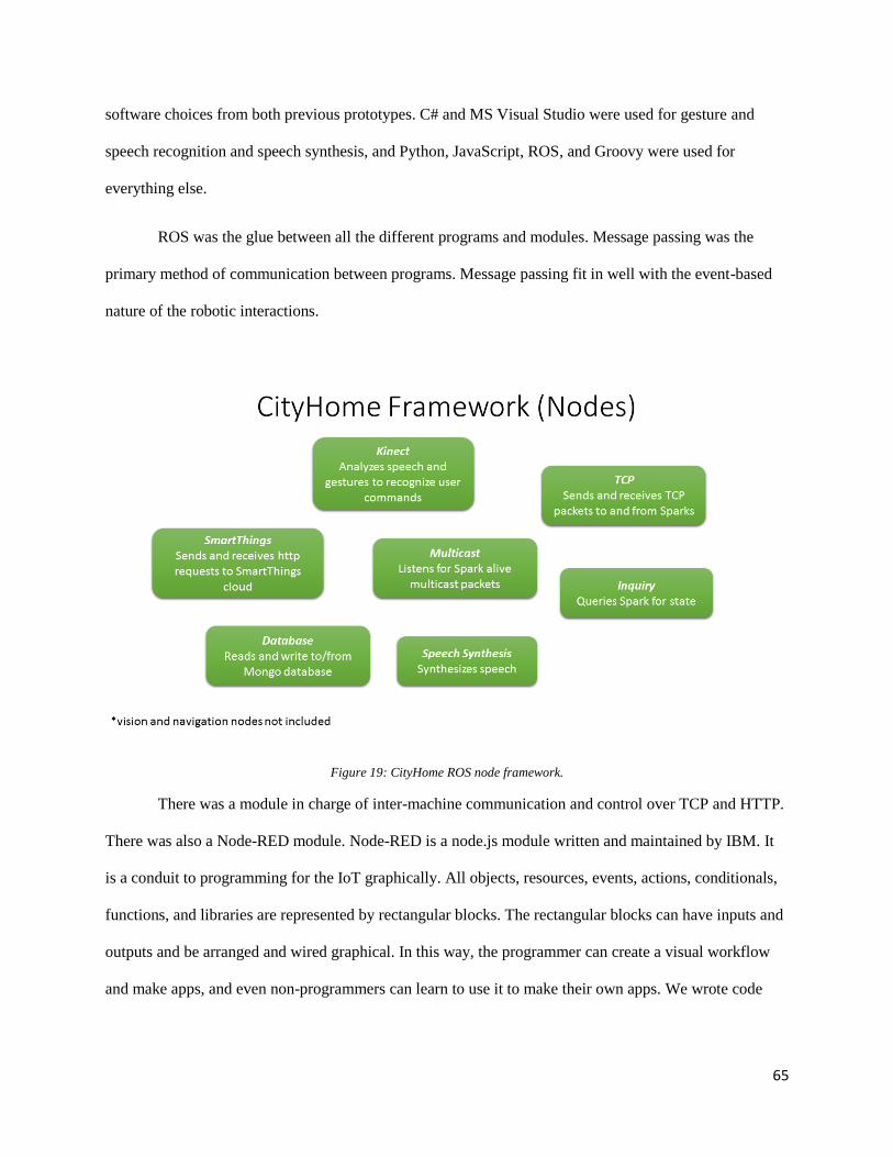
65
software choices from both previous prototypes. C# and MS Visual Studio were used for gesture and
speech recognition and speech synthesis, and Python, JavaScript, ROS, and Groovy were used for
everything else.
ROS was the glue between all the different programs and modules. Message passing was the
primary method of communication between programs. Message passing fit in well with the event-based
nature of the robotic interactions.
Figure 19: CityHome ROS node framework.
There was a module in charge of inter-machine communication and control over TCP and HTTP.
There was also a Node-RED module. Node-RED is a node.js module written and maintained by IBM. It
is a conduit to programming for the IoT graphically. All objects, resources, events, actions, conditionals,
functions, and libraries are represented by rectangular blocks. The rectangular blocks can have inputs and
outputs and be arranged and wired graphical. In this way, the programmer can create a visual workflow
and make apps, and even non-programmers can learn to use it to make their own apps. We wrote code
66
encapsulations (in HTML and JavaScript) to interface with ROS and represent and control the different
smart, connected elements in the room. Figure 9 in section 3.4.2 shows a Node-RED app.
There was a MongoDB database for storing information about the state of the room and elements
and keeping track of events. There was a website that read from the database and displayed the state of
everything, and it would update every time a change was made to the database. Dennis Garcia developed
the MongoDB data management and website.
The last software element of the prototype was the SmartThings API integration. SmartThings is
a smart home automation company. They sell many products, such as lights, contact sensors, presence
sensors, temperature sensors, motion sensors, and locks. All their devices are connected to a SmartThings
hub, a wireless router with many different antennas supporting many IoT wireless protocols, like ZigBee
and Z-Wave. Their router can also interface with third party devices and connects to the Internet and the
SmartThings cloud. Data and events are collected in the cloud, and the objects are controlled via
commands sent from the cloud. Apps can run on the cloud. SmartThings provides a smartphone app to
monitor and control your devices and download and install cloud apps. They also provide a RESTFUL
web API to allow programmers to write apps and monitor and control devices with HTTP calls. The apps
running in the cloud are written in Groovy. We made a cloud app to allow interfacing with the ROS
platform. This way, Philips Hue lights and SmartThings sensors could be accessed and control similarly
to how the microcontrollers were being controlled with the same platform and API.
5.6.3 Elements
There is a big closet in the room. The closet has wheels and is connected to a motor-equipped lead screw
along the floor and wall. This allows the closet to translate horizontally on the floor along the wall and is
intended to make your space dynamic and reconfigurable effortlessly.
There is also a queen bed in the room. The bed is connected to vertical motor-equipped lead
screws running from the floor to the ceiling. This allows the bed to be cantilevered and translate
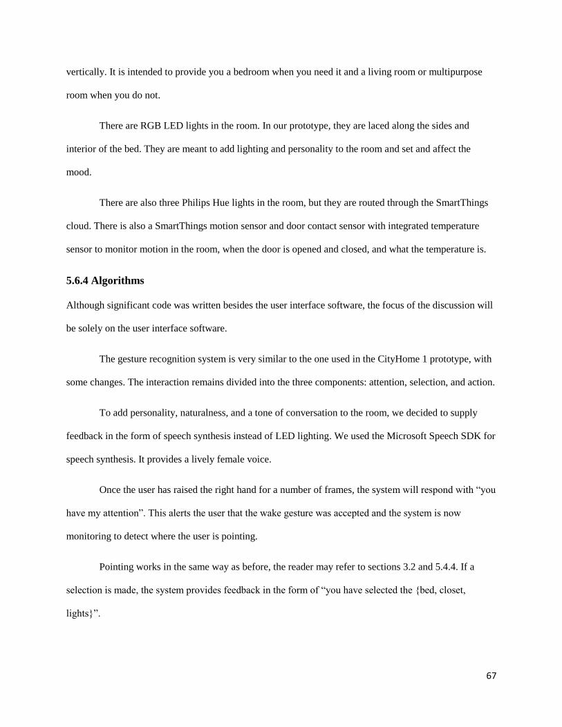
67
vertically. It is intended to provide you a bedroom when you need it and a living room or multipurpose
room when you do not.
There are RGB LED lights in the room. In our prototype, they are laced along the sides and
interior of the bed. They are meant to add lighting and personality to the room and set and affect the
mood.
There are also three Philips Hue lights in the room, but they are routed through the SmartThings
cloud. There is also a SmartThings motion sensor and door contact sensor with integrated temperature
sensor to monitor motion in the room, when the door is opened and closed, and what the temperature is.
5.6.4 Algorithms
Although significant code was written besides the user interface software, the focus of the discussion will
be solely on the user interface software.
The gesture recognition system is very similar to the one used in the CityHome 1 prototype, with
some changes. The interaction remains divided into the three components: attention, selection, and action.
To add personality, naturalness, and a tone of conversation to the room, we decided to supply
feedback in the form of speech synthesis instead of LED lighting. We used the Microsoft Speech SDK for
speech synthesis. It provides a lively female voice.
Once the user has raised the right hand for a number of frames, the system will respond with “you
have my attention”. This alerts the user that the wake gesture was accepted and the system is now
monitoring to detect where the user is pointing.
Pointing works in the same way as before, the reader may refer to sections 3.2 and 5.4.4. If a
selection is made, the system provides feedback in the form of “you have selected the {bed, closet,
lights}”.
68
Now in the action phase, the user must perform gestures particular to the object he or she is
controlling. For the bed, this implies swiping up or down from the original right hand position to move it
up or down. This works well as the bed has binary up and down states and cannot be controlled to stay in
between the two ends of the lead screws.
Controlling the closet implies moving the right hand left or right to move the closet left or right.
Unlike the bed, the closet position can take any point between the two ends of the lead screw. Therefore,
the swipe and forget gesture is rather limiting. Instead, three imaginary zones are drawn in front of the
user, and they are divided vertically along the x-axis into a left zone, a stop zone, and a right zone.
Moving the right hand between the zones sends the appropriate command to the closet microcontroller.
To end the gesture, the user must raise the left hand above the head. The zone in which the right hand is in
when the left hand is raised is the last command that is sent to the closet. This was intended to be a feature
to allow the user to send the closet all the way in one direction without having to be standing and raising
the arms the entire time.
Controlling the lights also works the same way as before. Raising the left hand above the head
will set the lights to the color the right hand was at in that frame.
After exiting the action state, the system stops and returns to the sleep/attention state.
The speech recognition system uses the Microsoft Speech SDK and the US English language
packages. The speech recognition engine supports two modes. The first mode is dictation. The system
listens for all words in the language pack dictionary and returns phrases as it detects them. This mode
trades flexibility for accuracy; since it looks for all words, it is not as accurate as the fixed grammar
mode. The second mode is fixed grammar. The programmer specifies all the possible phrases the user
may say. The system then fixates to only look for those phrases, increasing accuracy but forcing the user
to use only the specified phrases. Because we are dealing with a sometimes-noisy home environment, (the
69
motors make significant noise moving the furniture) and testing with multiple speakers, the fixed
grammar mode was chosen.
In keeping with the three-component system model, we decided the system should have a wake
word. We chose the word to be “home”. When the user says “home”, the system responds with “hello”
upon waking, and is now listening for a command.
To move the bed, the user can then say “move the bed {up, down}”. The system then responds
with “I will move the bed {up, down} for you”. Unfortunately, the bed’s electronics were not ready in
time, and the code at the time of this writing does not send any command to the bed microcontroller.
To move the closet, the user can say “move the closet {left, right}”. The system responds with
“moving the closet {left, right}” and sends the appropriate command to the closet. The user can then let
the closet reach one of the ends of the lead screws. Otherwise, the user can say “stop” at any time. The
system responds with “stopping the closet” and stops the closet. As currently designed, the move
command does not exit the action state of the system; the user must say “stop” for this.
To change the color of the lights, the user can say “change the lights to [color]”. The system does
not respond with speech; it instead just changes the lights, as this is feedback enough. Unfortunately, the
programmer must specify all the allowable colors. The colors are set at full intensity; intensity control
was not implemented at the time of this writing. Saying the command does exit the action state of the
system.
We also explored the integration of crossing the two modalities. This was a means to increase the
options available for control by the user. The user could use the either the wake word or wake gesture to
get the attention of the system. Once attention was attained, the user could either say an entire selection
and control phrase (like “move the closet left”). Alternatively, the user could point at an object. Once
selection was obtained, the user could either perform the control gesture, or say an abbreviated command
phrase. For example, if the user had pointed at the bed, he or she can simply say “{up, down}”. Similarly,
70
the user can point at the closet and say “{left, right}”. Lastly, the user can point at the lights and say
“[color]”.
5.6.5 Limitations
Most of the issues encountered involved the speech and gesture recognition systems. The limitations of
these systems are discussed in sections 6.3.3 and 6.3.4.

71
Chapter 6
6 User Studies
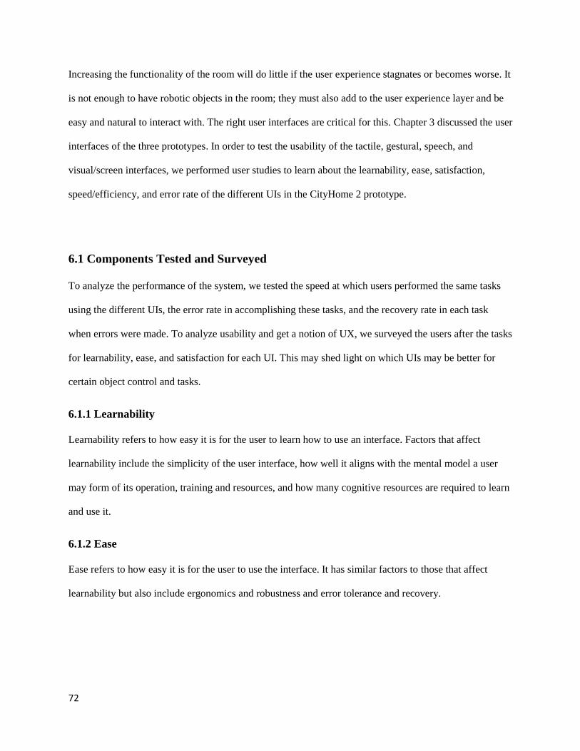
72
Increasing the functionality of the room will do little if the user experience stagnates or becomes worse. It
is not enough to have robotic objects in the room; they must also add to the user experience layer and be
easy and natural to interact with. The right user interfaces are critical for this. Chapter 3 discussed the user
interfaces of the three prototypes. In order to test the usability of the tactile, gestural, speech, and
visual/screen interfaces, we performed user studies to learn about the learnability, ease, satisfaction,
speed/efficiency, and error rate of the different UIs in the CityHome 2 prototype.
6.1 Components Tested and Surveyed
To analyze the performance of the system, we tested the speed at which users performed the same tasks
using the different UIs, the error rate in accomplishing these tasks, and the recovery rate in each task
when errors were made. To analyze usability and get a notion of UX, we surveyed the users after the tasks
for learnability, ease, and satisfaction for each UI. This may shed light on which UIs may be better for
certain object control and tasks.
6.1.1 Learnability
Learnability refers to how easy it is for the user to learn how to use an interface. Factors that affect
learnability include the simplicity of the user interface, how well it aligns with the mental model a user
may form of its operation, training and resources, and how many cognitive resources are required to learn
and use it.
6.1.2 Ease
Ease refers to how easy it is for the user to use the interface. It has similar factors to those that affect
learnability but also include ergonomics and robustness and error tolerance and recovery.

73
6.1.3 Satisfaction
Perhaps the most important general measure of usability, satisfaction refers to how content the user is
with the UI and UX. Even if the UI is easy to learn and use (which generally correlates with satisfaction),
if the users are not satisfied with the UI, then UX will suffer.
Learnability, ease, and satisfaction were all surveyed for the different UIs on the different objects
tested on 7-point Likert scale ratings.
6.2 Experiment
The testable objects consisted of the closet and lights. The gesture and speech modalities exist for
both objects. The closet also has a tactile modality, a FSR that can measure the amount of force applied in
two directions on the closet’s handle. The lights also have a visual modality, a Node-RED web app that
allows the user to change the color from a computer or phone screen. We also implemented a cross
modality, referring to the use of both gestures and speech to accomplish a single task.
Between the two objects and five modalities, we came up with eight tasks for each user to
perform twice. They involve moving the closet with the touch sensor (1), gestures (2), speech (3), cross
(4), and changing the lights with gestures (5), speech (6), cross (7), and the visual screen interface (8). For
the study, 20 users participated.
6.3 Results and Conclusions
6.3.1 Performance
For the closet, we timed how long it took the user to move the closet a set same amount of distance with
each UI. The aggregate results are below. Error bars represent standard error.
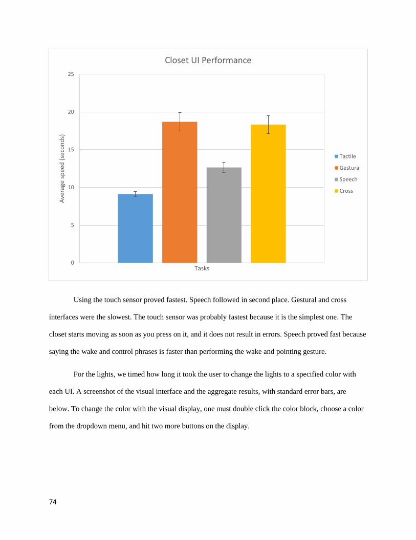
74
Using the touch sensor proved fastest. Speech followed in second place. Gestural and cross
interfaces were the slowest. The touch sensor was probably fastest because it is the simplest one. The
closet starts moving as soon as you press on it, and it does not result in errors. Speech proved fast because
saying the wake and control phrases is faster than performing the wake and pointing gesture.
For the lights, we timed how long it took the user to change the lights to a specified color with
each UI. A screenshot of the visual interface and the aggregate results, with standard error bars, are
below. To change the color with the visual display, one must double click the color block, choose a color
from the dropdown menu, and hit two more buttons on the display.
0
5
10
15
20
25
Ave
rage
sp
eed
(se
con
ds)
Tasks
Closet UI Performance
Tactile
Gestural
Speech
Cross
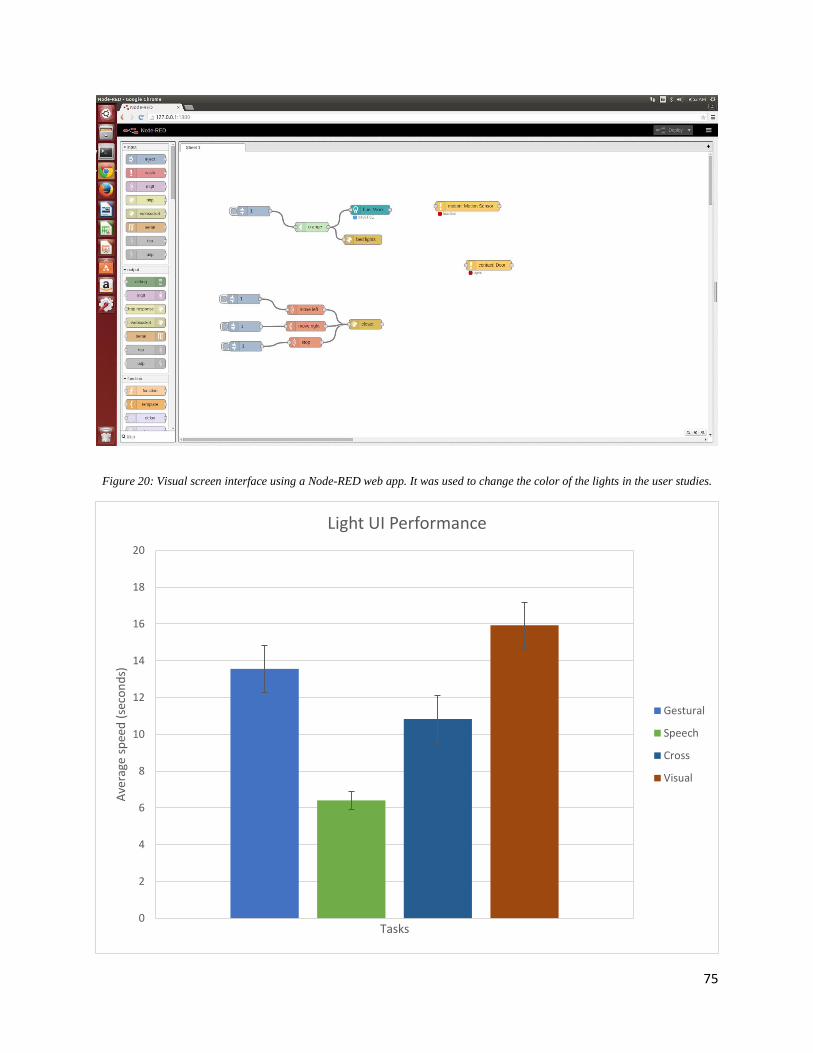
75
Figure 20: Visual screen interface using a Node-RED web app. It was used to change the color of the lights in the user studies.
0
2
4
6
8
10
12
14
16
18
20
Ave
rage
sp
eed
(se
con
ds)
Tasks
Light UI Performance
Gestural
Speech
Cross
Visual
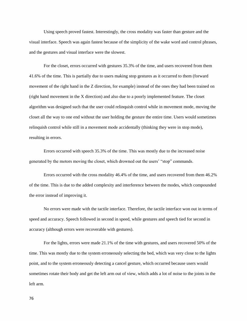
76
Using speech proved fastest. Interestingly, the cross modality was faster than gesture and the
visual interface. Speech was again fastest because of the simplicity of the wake word and control phrases,
and the gestures and visual interface were the slowest.
For the closet, errors occurred with gestures 35.3% of the time, and users recovered from them
41.6% of the time. This is partially due to users making stop gestures as it occurred to them (forward
movement of the right hand in the Z direction, for example) instead of the ones they had been trained on
(right hand movement in the X direction) and also due to a poorly implemented feature. The closet
algorithm was designed such that the user could relinquish control while in movement mode, moving the
closet all the way to one end without the user holding the gesture the entire time. Users would sometimes
relinquish control while still in a movement mode accidentally (thinking they were in stop mode),
resulting in errors.
Errors occurred with speech 35.3% of the time. This was mostly due to the increased noise
generated by the motors moving the closet, which drowned out the users’ “stop” commands.
Errors occurred with the cross modality 46.4% of the time, and users recovered from them 46.2%
of the time. This is due to the added complexity and interference between the modes, which compounded
the error instead of improving it.
No errors were made with the tactile interface. Therefore, the tactile interface won out in terms of
speed and accuracy. Speech followed in second in speed, while gestures and speech tied for second in
accuracy (although errors were recoverable with gestures).
For the lights, errors were made 21.1% of the time with gestures, and users recovered 50% of the
time. This was mostly due to the system erroneously selecting the bed, which was very close to the lights
point, and to the system erroneously detecting a cancel gesture, which occurred because users would
sometimes rotate their body and get the left arm out of view, which adds a lot of noise to the joints in the
left arm.
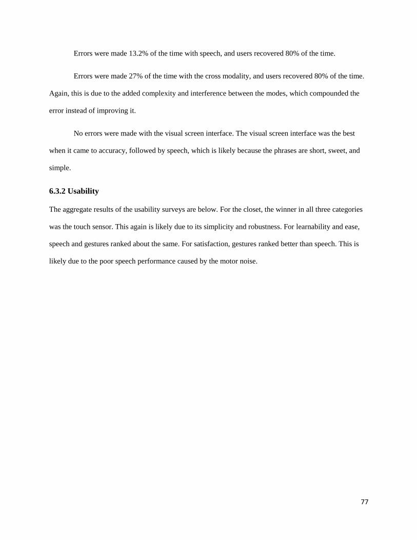
77
Errors were made 13.2% of the time with speech, and users recovered 80% of the time.
Errors were made 27% of the time with the cross modality, and users recovered 80% of the time.
Again, this is due to the added complexity and interference between the modes, which compounded the
error instead of improving it.
No errors were made with the visual screen interface. The visual screen interface was the best
when it came to accuracy, followed by speech, which is likely because the phrases are short, sweet, and
simple.
6.3.2 Usability
The aggregate results of the usability surveys are below. For the closet, the winner in all three categories
was the touch sensor. This again is likely due to its simplicity and robustness. For learnability and ease,
speech and gestures ranked about the same. For satisfaction, gestures ranked better than speech. This is
likely due to the poor speech performance caused by the motor noise.
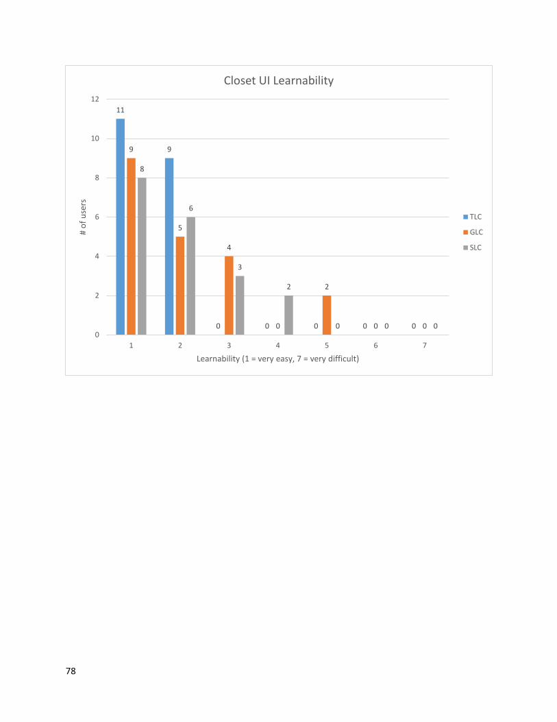
78
11
9
0 0 0 0 0
9
5
4
0
2
0 0
8
6
3
2
0 0 00
2
4
6
8
10
12
1 2 3 4 5 6 7
# o
f u
sers
Learnability (1 = very easy, 7 = very difficult)
Closet UI Learnability
TLC
GLC
SLC
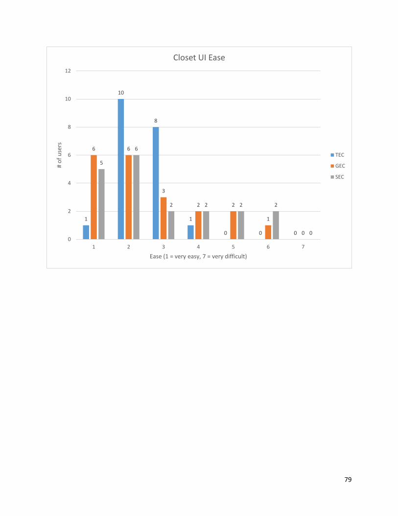
79
1
10
8
1
0 0 0
6 6
3
2 2
1
0
5
6
2 2 2 2
00
2
4
6
8
10
12
1 2 3 4 5 6 7
# o
f u
sers
Ease (1 = very easy, 7 = very difficult)
Closet UI Ease
TEC
GEC
SEC
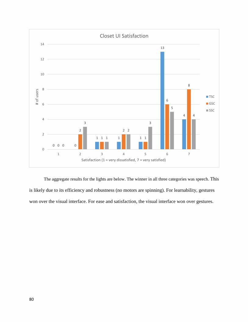
80
The aggregate results for the lights are below. The winner in all three categories was speech. This
is likely due to its efficiency and robustness (no motors are spinning). For learnability, gestures
won over the visual interface. For ease and satisfaction, the visual interface won over gestures.
0 0
1 1 1
13
4
0
2
1
2
1
6
8
0
3
1
2
3
5
4
0
2
4
6
8
10
12
14
1 2 3 4 5 6 7
# o
f u
sers
Satisfaction (1 = very dissatisfied, 7 = very satisfied)
Closet UI Satisfaction
TSC
GSC
SSC
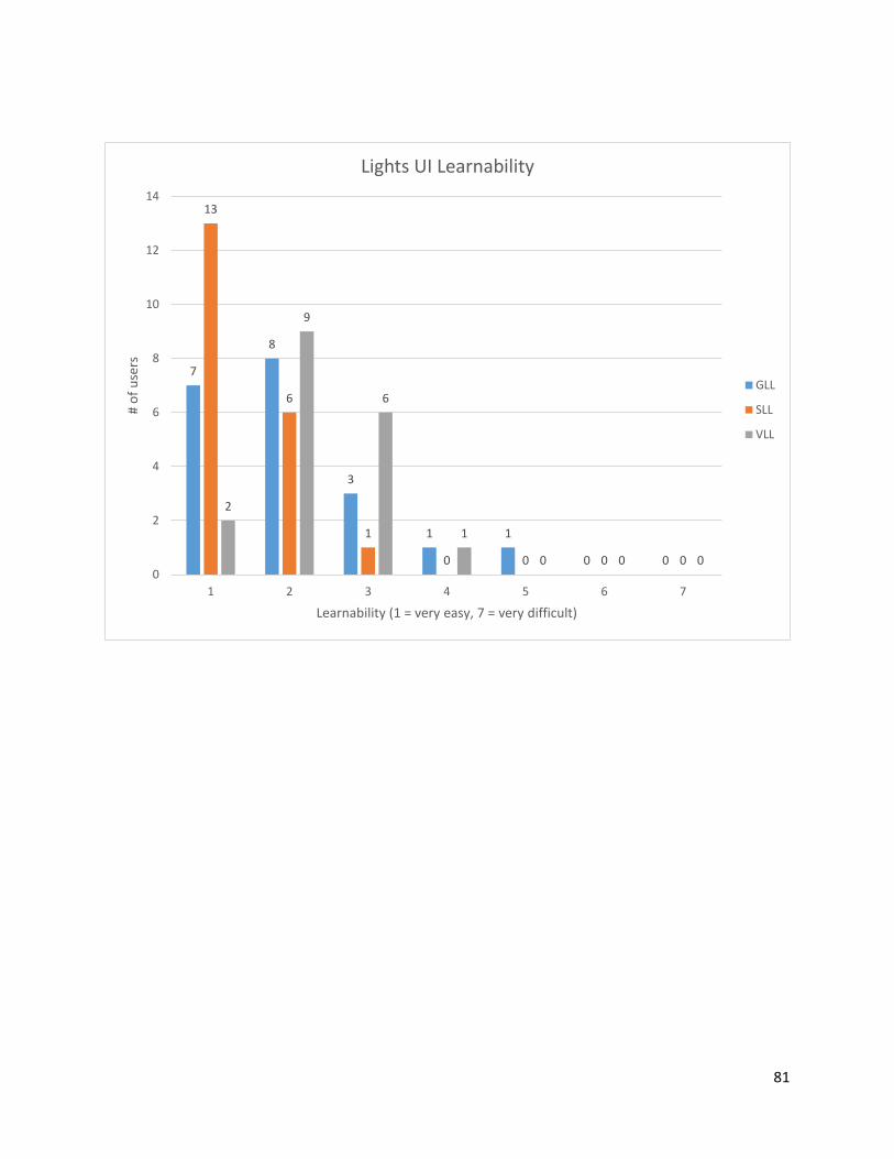
81
7
8
3
1 1
0 0
13
6
1
0 0 0 0
2
9
6
1
0 0 00
2
4
6
8
10
12
14
1 2 3 4 5 6 7
# o
f u
sers
Learnability (1 = very easy, 7 = very difficult)
Lights UI Learnability
GLL
SLL
VLL
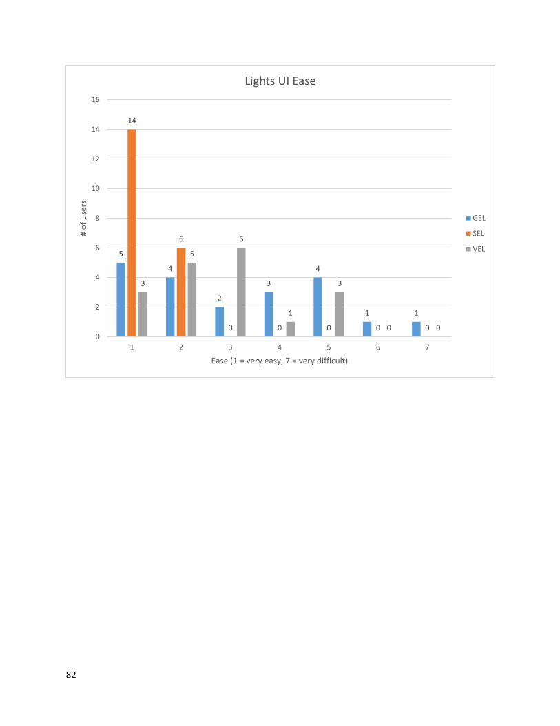
82
5
4
2
3
4
1 1
14
6
0 0 0 0 0
3
5
6
1
3
0 00
2
4
6
8
10
12
14
16
1 2 3 4 5 6 7
# o
f u
sers
Ease (1 = very easy, 7 = very difficult)
Lights UI Ease
GEL
SEL
VEL
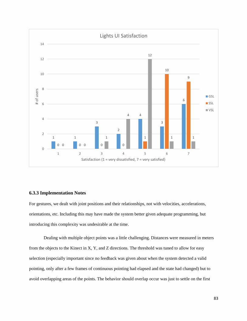
83
6.3.3 Implementation Notes
For gestures, we dealt with joint positions and their relationships, not with velocities, accelerations,
orientations, etc. Including this may have made the system better given adequate programming, but
introducing this complexity was undesirable at the time.
Dealing with multiple object points was a little challenging. Distances were measured in meters
from the objects to the Kinect in X, Y, and Z directions. The threshold was tuned to allow for easy
selection (especially important since no feedback was given about when the system detected a valid
pointing, only after a few frames of continuous pointing had elapsed and the state had changed) but to
avoid overlapping areas of the points. The behavior should overlap occur was just to settle on the first
1 1
3
2
4
3
6
0 0 0 0
1
10
9
0 0
1
4
12
1 1
0
2
4
6
8
10
12
14
1 2 3 4 5 6 7
# o
f u
sers
Satisfaction (1 = very dissatisfied, 7 = very satisfied)
Lights UI Satisfaction
GSL
SSL
VSL
84
object in the list with which the system computed a trigger dot product. This sometimes led to false
positives and the system selecting an object the user did not intend to choose.
It was also difficult to keep track of all objects, states, and possible actions by the user. In
particular, we learned to correct for some things only after testing out the system with other users who did
not know about how the system was programmed and seeing how they acted and how the system reacted.
Even then, it was particularly challenging coming up with good ways for recovery and cancellations.
The Kinect data was sometimes very noisy and inaccurate. In particular, if the user did not keep
his or her body facing the Kinect, something a little unnatural when dealing with objects in different
locations, the skeletal joints would become erroneous. The same thing happens if the user wears loose
attire, like scarves, jackets, purses, etc. The Kinect would sometimes mistake objects for people as well,
and these skeletons were almost always very noisy.
For speech, a fixed grammar was used. This increased the accuracy of detections and overall
made the system better. However, this also forced us to specify the phrases to be said and forces the user
to know and say those phrases. Luckily, even when users strayed from the phrase by a word or two, the
detection was usually still made.
Integrating speech recognition into the system showed the difficulty that acoustic noise creates in
speech recognition. Although the Kinect has a high quality phased microphone array, much better than
computer-integrated microphones, performance would still suffer when other people were talking in the
background or when the motors were making noise in moving the closet. This was especially critical, as
control is most needed when the furniture is moving, but this is precisely when speech detection suffered
most.
Crossing the modalities was probably the most complicated programming-wise and could become
complicated if the user did not know well how it works. This is because you have two modalities
competing to control the system states, and better programming could have gone into this. Allowing for
85
the crossing of the modalities would sometimes result in unwanted interference between the two modes.
The user’s speech and gestures would sometimes not match, confusing the system and resulting in
undesired behavior. For example, the user could say “up” while relaxing and dropping the hand (a move
down gesture). Overall, this led to more errors.
Some things worked quite well and easily too. The attention and cancellation gesture (raising the
right hand above the head and raising the left hand above the head, respectively) were detected well. The
swipe up and down gestures were detected well. This is because they are simple and have clearly defined
rule configurations. Pointing also almost always resulted in a detection and usually in correct detections.
Users also liked how the color gestural system worked.
When noise was limited and the phrases were mostly correct, speech detections were almost
always spot on. Although the project is still at a prototype level, and speech and gesture recognition still
need to improve, people are excited to be in sufficiently robust multimodal UI smart home environments.
6.3.4 Improvements
A few things can improve the system. Utilizing more data besides joint positions, like velocities,
accelerations, and orientations, may prove beneficial. The system should compute dot products of all
objects and choose the object closest to -1 instead of the first one below the threshold. If the user points at
an overlapping area, the system should use speech synthesis to ask the user which of the objects he or she
is trying to select.
Learning more about the gestures one can expect users to make while using the system and trying
to account for those would also be helpful. To increase gestural accuracy, taking advantage of the fact that
the Microsoft Kinect SDK differentiates between confident and not confident joints and only analyzing a
frame where all the relevant joints are confident would likely be effective. Looking into digital signal
processing techniques to filter out motor noise would probably improve the system. Lastly, the cross

86
modality should be implemented differently. Instead of the competitive method used now, trying to find a
more cooperative method in which they help reinforce each other and make correct detections would be
worthwhile.
6.4 Other Qualitative Results and Conclusions
Other interesting questions were asked in the end-of-study survey. The aggregate results are discussed
below.
Users were asked to rank the modalities in order of preference from 1 to 5, 1 being the most
preferred. The results are in the bar graph above. It is too close to call with touch, gestures, speech, and
3.12.75
2.55 2.6
4.15
0
0.5
1
1.5
2
2.5
3
3.5
4
4.5
5
Touch Rank Gesture Rank Speech Rank Cross Rank Phone/Screen Rank
Ave
rage
Ran
kin
g (L
ow
er is
bet
ter)
UI Rankings
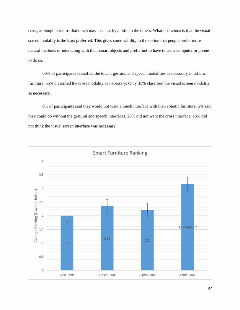
87
cross, although it seems that touch may lose out by a little to the others. What is obvious is that the visual
screen modality is the least preferred. This gives some validity to the notion that people prefer more
natural methods of interacting with their smart objects and prefer not to have to use a computer or phone
to do so.
60% of participants classified the touch, gesture, and speech modalities as necessary in robotic
furniture. 55% classified the cross modality as necessary. Only 35% classified the visual screen modality
as necessary.
0% of participants said they would not want a touch interface with their robotic furniture. 5% said
they could do without the gestural and speech interfaces. 20% did not want the cross interface. 15% did
not think the visual screen interface was necessary.
2
2.352.2
3.166666667
0
0.5
1
1.5
2
2.5
3
3.5
4
Bed Rank Closet Rank Lights Rank Table Rank
Ave
rage
Ran
kin
g (L
ow
er is
bet
ter)
Smart Furniture Ranking
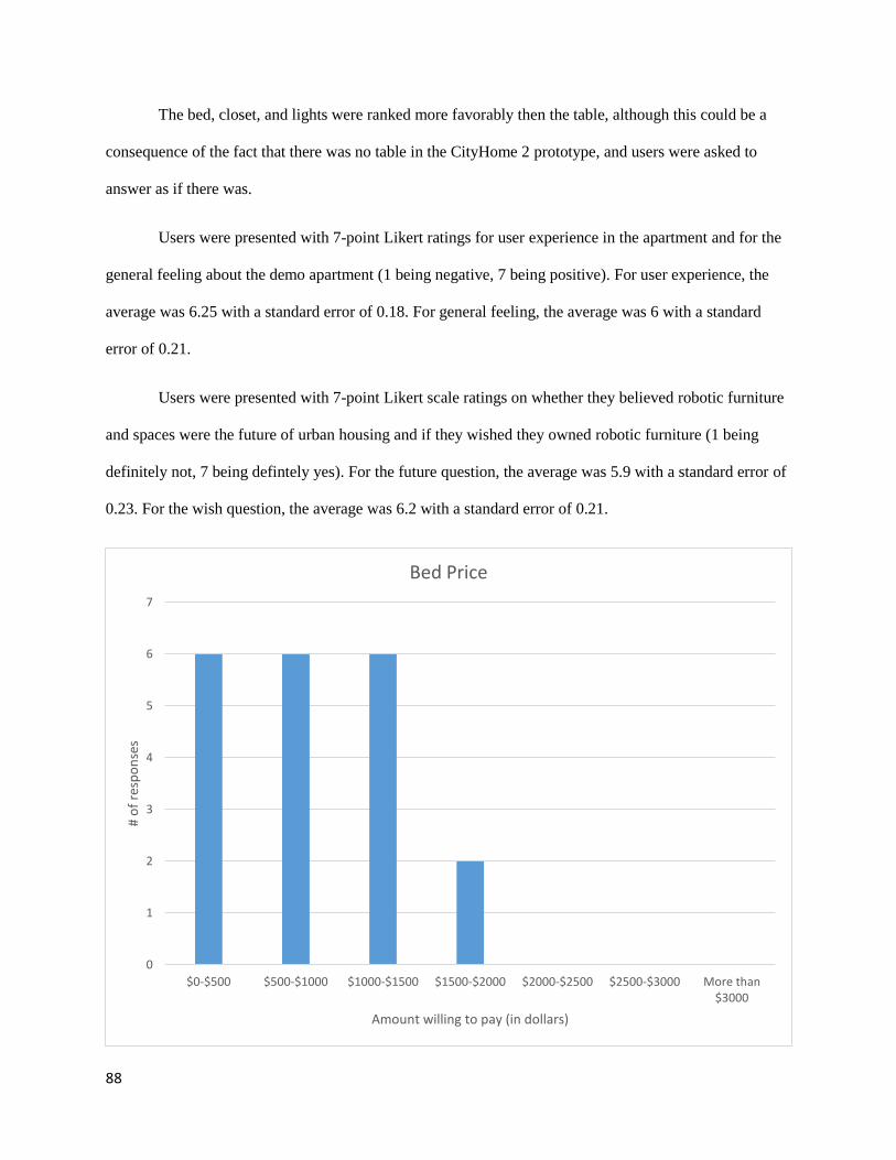
88
The bed, closet, and lights were ranked more favorably then the table, although this could be a
consequence of the fact that there was no table in the CityHome 2 prototype, and users were asked to
answer as if there was.
Users were presented with 7-point Likert ratings for user experience in the apartment and for the
general feeling about the demo apartment (1 being negative, 7 being positive). For user experience, the
average was 6.25 with a standard error of 0.18. For general feeling, the average was 6 with a standard
error of 0.21.
Users were presented with 7-point Likert scale ratings on whether they believed robotic furniture
and spaces were the future of urban housing and if they wished they owned robotic furniture (1 being
definitely not, 7 being defintely yes). For the future question, the average was 5.9 with a standard error of
0.23. For the wish question, the average was 6.2 with a standard error of 0.21.
0
1
2
3
4
5
6
7
$0-$500 $500-$1000 $1000-$1500 $1500-$2000 $2000-$2500 $2500-$3000 More than$3000
# o
f re
spo
nse
s
Amount willing to pay (in dollars)
Bed Price
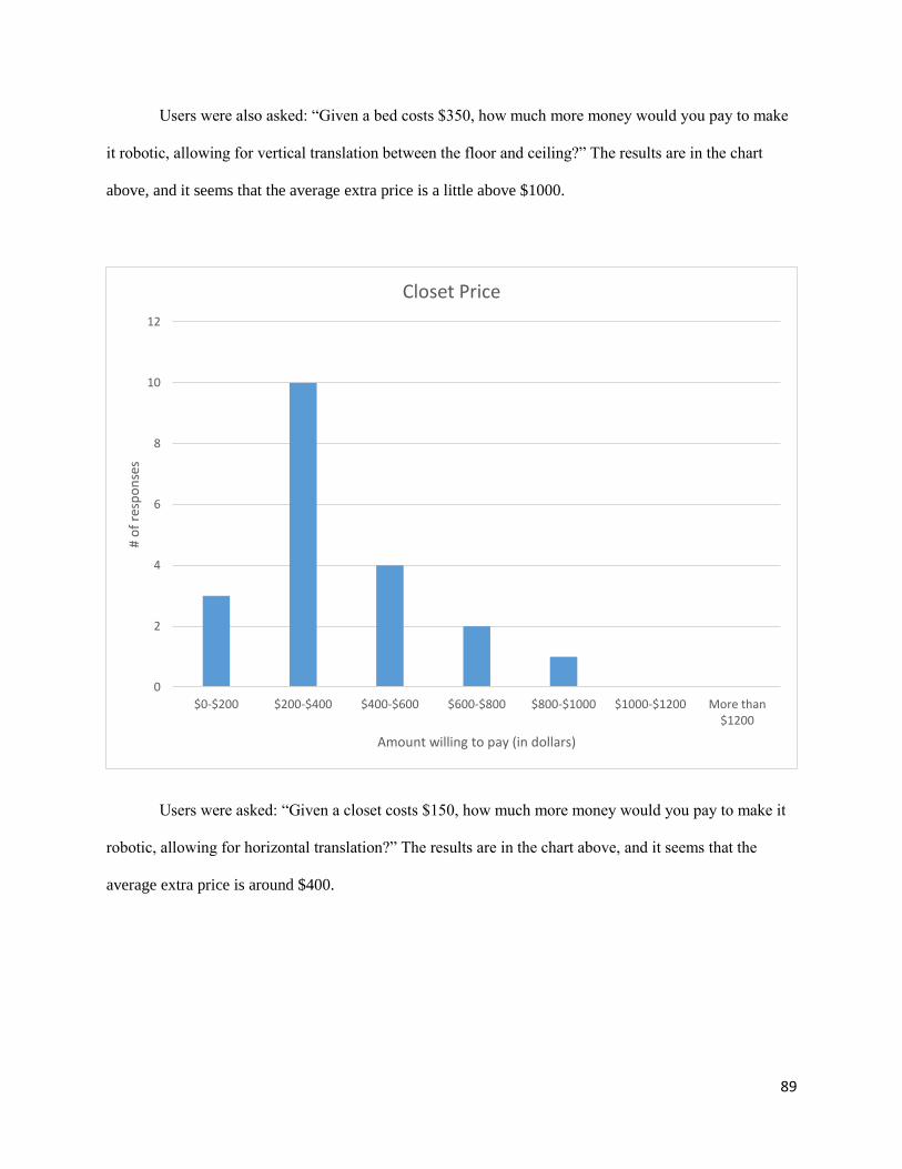
89
Users were also asked: “Given a bed costs $350, how much more money would you pay to make
it robotic, allowing for vertical translation between the floor and ceiling?” The results are in the chart
above, and it seems that the average extra price is a little above $1000.
Users were asked: “Given a closet costs $150, how much more money would you pay to make it
robotic, allowing for horizontal translation?” The results are in the chart above, and it seems that the
average extra price is around $400.
0
2
4
6
8
10
12
$0-$200 $200-$400 $400-$600 $600-$800 $800-$1000 $1000-$1200 More than$1200
# o
f re
spo
nse
s
Amount willing to pay (in dollars)
Closet Price
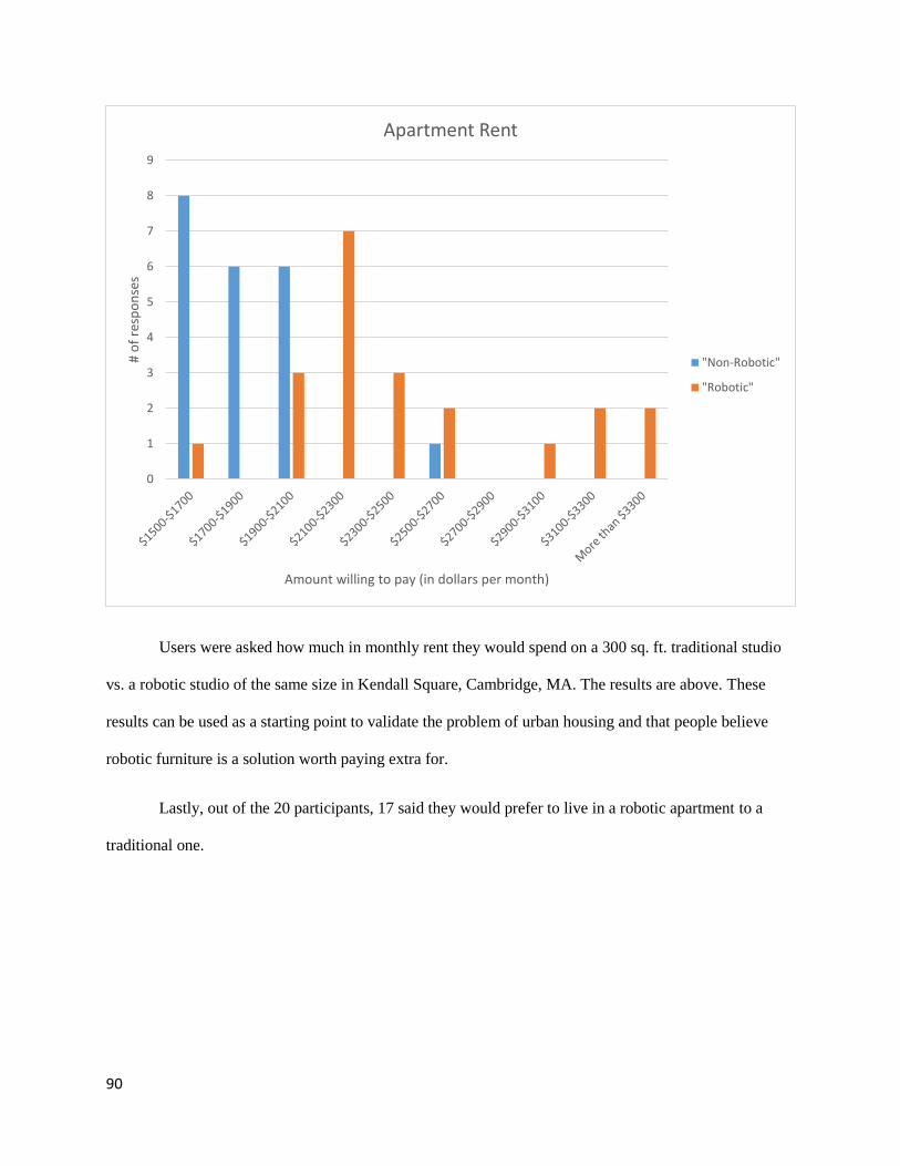
90
Users were asked how much in monthly rent they would spend on a 300 sq. ft. traditional studio
vs. a robotic studio of the same size in Kendall Square, Cambridge, MA. The results are above. These
results can be used as a starting point to validate the problem of urban housing and that people believe
robotic furniture is a solution worth paying extra for.
Lastly, out of the 20 participants, 17 said they would prefer to live in a robotic apartment to a
traditional one.
0
1
2
3
4
5
6
7
8
9
# o
f re
spo
nse
s
Amount willing to pay (in dollars per month)
Apartment Rent
"Non-Robotic"
"Robotic"
91
Chapter 7
7 Conclusion
92
7.1 Application Spaces
The research generated by the CityHome team over the years show that robotic furniture does have
considerable potential to be a solution for the urban space problem. Mechatronic systems and robotic
furniture with capable mechanics, electronics, and software will be crucial to deploying this technology,
and further development is still needed on these fronts. User interfaces are also a critical part of the
technology, and people want robust interfaces different from the traditional tactile and visual ones. People
are willing to pay for this technology, further validating the problem.
There are many potential application spaces for this technology, including current apartments,
studios, and micro apartments, new apartments under construction, hotels, restaurants, bars, retail spaces,
hospitals, and transportation spaces. (Larrea-Tamayo, 2015)
7.2 Impacts and Milestones
The CityHome project has clear potential to make big impact and has received considerable attention and
press over the years.
CityHome has received attention and positive reviews during MIT Media Lab’s Members’
Weeks, during which many different company representatives travel to the Media Lab and inspect the
projects their funding has sponsored. In fact, because of the CityHome project, IKEA, a low cost furniture
retailer, became a Media Lab member in January 2015 and funded CityHome.
A business plan about commercializing the CityHome technology was developed and entered into
the MIT $100K competition and made it to the semi-finals. Hasier Larrea, the project manager, will give a
TEDx Cambridge talk in the summer of 2015 about the urban future and CityHome’s developments.
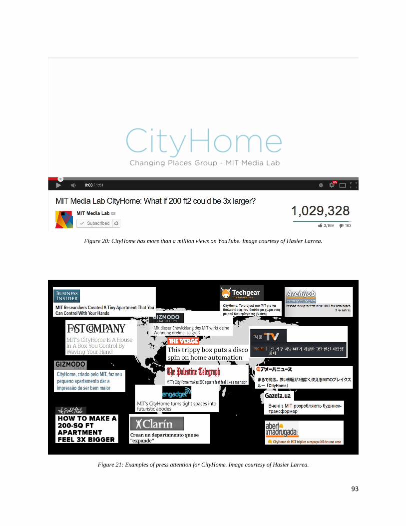
93
Figure 20: CityHome has more than a million views on YouTube. Image courtesy of Hasier Larrea.
Figure 21: Examples of press attention for CityHome. Image courtesy of Hasier Larrea.
94
Bibliography Borenstein, G. (2012). Making Things See: 3D vision with Kinect, Processing, Arduino, and MakerBot
(Make: Books). Maker Media, Inc.
Dobbs, R., Remes, J., Manyika, J., Roxburgh, C., Smit, S., & Schaer, F. (2012). Urban world: Cities and
the rise of the consuming class. McKinsey Global Institute.
Guinard, D. (2011). A Web of Things Application Architecture Integrating the Real-World into the Web.
Zurich: ETH Zurich.
Herr, H., & Duval, J.-F. (n.d.). FlexSEA: Flexible, Scalable Electronics Architecture for Prosthetic and
Robotic Applications.
Larrea-Tamayo, H. (2015). ARkits: Architectural Robotics kit. Boston: MIT.
Marcus, A. (1998). Metaphor design for user interfaces. Cconference Summary on Human Factors in
Computing Systems (pp. 129-130). New York: ACM.
Microsoft Corp. (2013). Kinect for Windows Human Interface Guidelines v1.8.
Patsadu, O., Nukoolkit, C., & Watanapa, B. (2012). Human Gesture Recognition Using the Kinect
Camera. Joint Conference on Computer Science and Software Engineering (JCSSE).