A Transient State Model for Predicting Maintenance Requirements

An analytical model for predicting transient flow into equally spaced ditch drains receiving water from a uniformly ponded field
G. Barua & W. Alam Department of Civil Engineering, Indian Institute of Technology Guwahati, India
Abstract
An analytical solution is worked out for predicting transient seepage into a network of parallely spaced ditch drains in a homogeneous and anisotropic soil overlying an impervious barrier and receiving water from a uniformly ponded field. The distance between the adjacent drains is assumed to be the same and the level of water in all the ditches are all considered as equal in the analysis. In order that only two-dimensional flow prevails in the flow spaces in between the drains, it is further assumed in the mathematical procedure that the field is of infinite extent. The correctness of the develop model is established by performing a MODFLOW check on it for a considered ditch drainage situation. The study shows that the rate of water entry at the surface of a soil from a uniformly ponded field to the ditch drains is of a relatively better uniformity at early times of a simulation and that this uniformity gets progressively reduced with the passage of time, particularly for situations where the anisotropy ratio (it is a quotient between the horizontal and vertical saturated hydraulic conductivities of a soil) of the soil is low. Further, the transient state duration of a ponded ditch drainage scenario may be considerable if the drains are being laid in a soil having low directional conductivity values and a high anisotropy ratio, more so if the drains are being installed relatively deeper into the ground. The solution provided here is important as it can be successfully employed for designing a network of ditch drains for cleaning a salt affected soil and also in reclaiming a water-stagnated area. Keywords: analytical solution, ponded field, equally spaced ditch drains, saturated directional conductivity, specific storage, anisotropy ratio, uniform depth of ponding.
www.witpress.com, ISSN 1743-3541 (on-line) WIT Transactions on Ecology and The Environment, Vol 171, © 2013 WIT Press
doi:10.2495/WRM130291
Water Resources Management VII 323
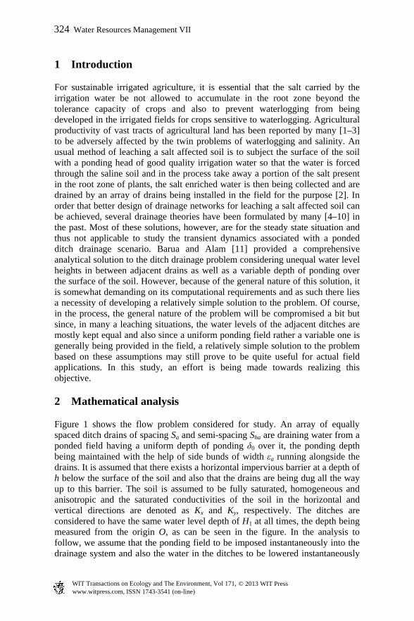
1 Introduction
For sustainable irrigated agriculture, it is essential that the salt carried by the irrigation water be not allowed to accumulate in the root zone beyond the tolerance capacity of crops and also to prevent waterlogging from being developed in the irrigated fields for crops sensitive to waterlogging. Agricultural productivity of vast tracts of agricultural land has been reported by many [1–3] to be adversely affected by the twin problems of waterlogging and salinity. An usual method of leaching a salt affected soil is to subject the surface of the soil with a ponding head of good quality irrigation water so that the water is forced through the saline soil and in the process take away a portion of the salt present in the root zone of plants, the salt enriched water is then being collected and are drained by an array of drains being installed in the field for the purpose [2]. In order that better design of drainage networks for leaching a salt affected soil can be achieved, several drainage theories have been formulated by many [4–10] in the past. Most of these solutions, however, are for the steady state situation and thus not applicable to study the transient dynamics associated with a ponded ditch drainage scenario. Barua and Alam [11] provided a comprehensive analytical solution to the ditch drainage problem considering unequal water level heights in between adjacent drains as well as a variable depth of ponding over the surface of the soil. However, because of the general nature of this solution, it is somewhat demanding on its computational requirements and as such there lies a necessity of developing a relatively simple solution to the problem. Of course, in the process, the general nature of the problem will be compromised a bit but since, in many a leaching situations, the water levels of the adjacent ditches are mostly kept equal and also since a uniform ponding field rather a variable one is generally being provided in the field, a relatively simple solution to the problem based on these assumptions may still prove to be quite useful for actual field applications. In this study, an effort is being made towards realizing this objective.
2 Mathematical analysis
Figure 1 shows the flow problem considered for study. An array of equally spaced ditch drains of spacing Sa and semi-spacing Sha
are draining water from a ponded field having a uniform depth of ponding δ0 over it, the ponding depth being maintained with the help of side bunds of width εa running alongside the drains. It is assumed that there exists a horizontal impervious barrier at a depth of h below the surface of the soil and also that the drains are being dug all the way up to this barrier. The soil is assumed to be fully saturated, homogeneous and anisotropic and the saturated conductivities of the soil in the horizontal and vertical directions are denoted as Kx and Ky,
respectively. The ditches are considered to have the same water level depth of H1 at all times, the depth being measured from the origin O, as can be seen in the figure. In the analysis to follow, we assume that the ponding field to be imposed instantaneously into the drainage system and also the water in the ditches to be lowered instantaneously
www.witpress.com, ISSN 1743-3541 (on-line) WIT Transactions on Ecology and The Environment, Vol 171, © 2013 WIT Press
324 Water Resources Management VII

Figure 1: Geometry of a fully penetrating ditch drainage system with equal water level heights in between adjacent drains and subjected to a uniform depth of ponding at the surface of the soil.
into a depth of H1, the water table being initially assumed to be standing up to the surface of the soil. Because of symmetry, we consider only half of the flow domain of fig. 1 for analysis. For mathematical convenience, we measure the x-axis to the right of the origin O as positive and the y-axis positive vertically downward of O. Calling the hydraulic head and time variables as and t,
respectively, the initial and boundary conditions of the flow problem for the domain OABKJO of fig. 1 can be expressed as
,0)0,,( tyx ,0 haSx ,0 hy (I)
,)0,,( ytyx ,0x ,0 1Hy (IIa)
,)0,,( 1Htyx ,0x ,1 hyH (IIb)
,0)0,,(
y
tyx
,hy ,0 haSx (III)
,0)0,,(
x
tyx
,haSx ,0 hy
(IV)
,)0,,( 0 tyx ,0y .0 haSx (V)
The solution of the problem requires that suitable hydraulic head function for the flow domain must be worked out so that the continuity equation corresponding to transient groundwater flow in a homogeneous and anisotropic aquifer
www.witpress.com, ISSN 1743-3541 (on-line) WIT Transactions on Ecology and The Environment, Vol 171, © 2013 WIT Press
Water Resources Management VII 325

,2
2
2
2
tK
S
yxK
y
sx
(1)
be satisfied along with the initial and boundary conditions as specified above. In eqn. (1), sS is the specific storage of the soil (the other symbols have already
been defined). Applying the transformation
,)/( 2/1 xKKX xy
(2)
to eqn. (1), we get the governing equation as
,)( 212
2
2
2
t
KyX
(3)
where
./)( 2
1 ys KSK (4)
Using the separation of variable method [12], a solution of eqn. (3) can be expressed as
)sin()cosh(
)](cosh[),,(
1
yNSN
XSNCtyX p
P
p hp
hpp
,)(
)(exp)sin()sin( 02
1
2
1 1
K
tyNXNA mn
nm
M
m
N
nmn
(5)
where
,)/( 2/1
haxyh SKKS (6)
,2
21
h
m S
mN
(7)
,2
21
h
nN n
(8)
,2
21
h
pN p
(9)
,)()()( 222nmmn NN (10)
pC and mnA are any constants, m, n and p are summation indices and M and N
are any natural numbers. An inspection of eqn. (5) shows that this equation fits boundary conditions III, IV and V directly. To get the constants ,pC we apply boundary conditions
IIa and IIb in the transformed space to eqn. (5) – the resultant expressions at 0X turn out to be
www.witpress.com, ISSN 1743-3541 (on-line) WIT Transactions on Ecology and The Environment, Vol 171, © 2013 WIT Press
326 Water Resources Management VII

,)sin( 01
yyNC p
P
pp
,0 1Hy
,)sin( 101
HyNC p
P
pp
.0 hy
By allowing P in the above equations to go to infinity, the constants pC can
then be evaluated by carrying out a Fourier series expansion in the range ;0 hy thus, pC can be expressed as
.)sin()()sin()(2
1
1
10
0
0
h
H
pp
H
p dyyNHdyyNyh
C
(11)
Simplifying the above integrals, we get
.)(
)sin(222
10
p
p
pp
N
HN
hhNC
(12)
There still remain the constants mnA of eqn. (5) to be evaluated. To get these
constants, we next apply the initial condition I to it in the horizontally transformed space; the ensuing relation works out to be
).sin()cosh(
)](cosh[)sin()sin(
10
1 1
yNSN
XSNCyNXNA p
Q
p hp
hppnm
M
m
N
nmn
(13)
Letting NM and in the above expression, the constants mnA can then be
evaluated by carrying out a Fourier expansion in the domain hSX 0 and
;0 hy the resultant expression for ,mnA thus, can be expressed as
dXdyyNXNSh
A n
hy
y
SX
X
mh
mn
h
)sin()sin()(22
0 0
0
hy
y
SX
X
P
p hp
hpp
h
h
SN
XSNC
Sh0 0 1
)cosh(
)](cosh[22
dXdyyNXNyN nmp )sin()sin()sin(
(14)
Naming the first and the second integrals of eqn. (14) as 1I
and ,2I
respectively, we get eqn (14) in a compact form as
.21 IIAmn (15)
These integrals, upon simplification, give
nmh NNhSI
114 01
(16)
www.witpress.com, ISSN 1743-3541 (on-line) WIT Transactions on Ecology and The Environment, Vol 171, © 2013 WIT Press
Water Resources Management VII 327

and for p n
P
p hppm
hmhpmp
h SNNN
SNSNNC
SI
1222
)cosh(])()[(
)]cos()[cos(2 (17)
and for p n
P
p np
np
np
np
pm
mp
h NN
hNN
NN
hNN
NN
NC
hSI
1222 )(2
])sin[(
)(2
])sin[(
])()[(
4
.)cosh(
)cos()cosh(
hp
hmhp
SN
SNSN (18)
Thus, all the constants of eqn. (5) are now being determined and the problem is hence solved. We would like to mention here that Barua and Alam [11] solved the flow problem of fig. 1 by considering a variable ponding field over the surface of the soil and unequal water level heights in the adjacent ditch drains. This solution is somewhat complex as, due to non-symmetry of flow in the flow space in between the drains, the entire flow domain OABCDHKJO was required to be considered in their analysis, running three different Fourier series to accommodate the boundaries at the ditch faces as well as on the surface of the soil. The solution provided here, however, as can be seen, is developed by considering only one half (because of symmetry of flow in the considered flow space) of the flow domain and is, hence, relatively much simpler than the one provided by Barua and Alam [11]. Further, it is important to note that these two solutions are totally independent of one another and the one obtained here cannot be reduced from Barua and Alam’s solution [11] as the flow domains, as mentioned before, over which these solutions are being developed are not the same. Discharge per unit length of a ditch from one side, ,shalfQ can be calculated
by applying the Darcy’s law on the desired side; thus, we have
,)()(
00
dyX
KKtQ
X
h
yxshalf
(19)
where yx KK is the equivalent conductivity of the medium [15]. Solving the
above integral, we have
.)cosh(
)sinh()()(
1 hp
hpP
ppyxshalf SN
SNCKKtQ
.)(
)(exp)(
1 12
1
2
M
m
N
n
mn
n
mmnyx
K
t
N
NAKK
(20)
www.witpress.com, ISSN 1743-3541 (on-line) WIT Transactions on Ecology and The Environment, Vol 171, © 2013 WIT Press
328 Water Resources Management VII

Similarly, the discharge per unit length obtained from the surface of the soil from a strip extending up to a distance of X from the origin O of fig. 1, ,topXQ
can be determined by applying now the Darcy’s law on the considered portion of the flow domain; the pertinent expression may be expressed as
,)()(0
dXy
KKtQX
yyxtopX
(21)
where .)/( 2/1axy KK Simplifying the above integral, we get
P
p hp
hppyxtopX SN
SNCKKtQ
1)cosh(
)](sinh[)()(
P
p hp
hppyx SN
XSNCKK
1)cosh(
)](sinh[)(
2
1
2
1 1 )(
)(exp)cos()(
K
tN
N
NAKK mn
m
M
m
N
n m
nmnyx
.)(
)(exp)cos()(
21
2
1 1
K
tXN
N
NAKK mn
m
M
m
N
n m
nmnyx
(22)
To obtain the top discharge per unit length of the ditches, ,topQ in between
the adjacent ditches from half of the flow domain, we need to simply take
hSX in the above equation. By dividing eqn. (22) by the total discharge per
unit length of the ditches )2( topQ the fraction of the discharge taking )( ftopXQ
place from a zone extending to a distance X from the origin O, can also be calculated. Further, time integrals of the discharge expressions can be carried out to estimate the volume of water entering through the sides of a ditch )( stotV
as
well as through the top surface )( topV of the flow domain in between the ditches
per unit length within any desired time interval t; performing these integrals, we get the expressions for these quantities as
tSN
SNCKKV
P
p hp
hppyxstot
)cosh(
)sinh()(2
1
1)(
exp)(
)()(2
21
2
1 12
21
K
t
N
NKAKK mn
M
m
N
n n
m
mnmnyx
(23)
and
tSN
SNCKKV
hp
hpP
ppyxtop
)cosh(
)](sinh[)(2
1
www.witpress.com, ISSN 1743-3541 (on-line) WIT Transactions on Ecology and The Environment, Vol 171, © 2013 WIT Press
Water Resources Management VII 329
M
m
N
n m
n
mnmnyx N
NKAKK
1 12
21
)(
)()(2
,1)(
)(exp)cos(
21
2
K
tN mn
m
(24)
respectively. The expressions derived above for the hydraulic head function, side and top discharges can be made to reduce to the steady state situation by simply taking the limit t in these equations; this will make the exponential terms to go away in these expressions, leaving behind all the terms independent of .t Once the steady state hydraulic head function is being evaluated, the steady state stream function can then be next evaluated by applying the following relation [13] to it in the transformed computational space
yXK
(25)
and
,
XyK
(26)
where is the stream function.
Taking the zero streamline to pass through )0,( in the horizontally
transformed space ),0)0,( (i.e., an expression for the stream function for
the flow domain OABKJO of fig. 1 can be expressed as
)cos()cosh(
)](sinh[)(),(
1
yNSN
XSNCKKyX p
hp
hpP
ppyx
.)cosh(
)](sinh[)(
1 hp
hpP
ppyx SN
SNCKK
(27)
Further, the stream function above can be easily normalized as under
,
)0,(
),(),(
h
n
S
yXyX
(28)
where n is the normalized stream function.
It is to be noted that all the expressions related to the volume, discharge and stream functions will reduce to infinity in the event of the condition 00 and
.0a This is because, in such a situation, in all these expressions, there will
occur an term
P
pphp NSNh
10 ,/)tanh()/2( an infinite series which diverges
since 1tanh( hpp SNLim and .)/1(1
P
ppN
www.witpress.com, ISSN 1743-3541 (on-line) WIT Transactions on Ecology and The Environment, Vol 171, © 2013 WIT Press
330 Water Resources Management VII

3 Discussion
Figure 2 shows the comparison of hydraulic heads as obtained from our developed model for a flow situation of fig. 1 at different times with corresponding predictions obtained from MODFLOW [14]. As may be observed, our predictions are found to be matching very closely with the corresponding numerically generated values, thereby verifying that the proposed model has been correctly developed. The figure also shows that most of the head gets dissipated around regions in close proximity to the drains, suggesting that, for a uniformly ponded ditch drainage setting, the majority of flow to the drains is taking place from locations lying closer to the drains and that at regions away from the drains, the flow activity is relatively much less.
Figure 2: Comparison of hydraulic head contours as obtained from the proposed solution for a flow situation of fig. 1 as shown with the corresponding MODFLOW generated contours at a few time intervals when εa=0.1 m and the soil parameters are taken as Ss=0.001 m-1 and Kx/Ky=1/1 (Kx=0.2 m/day, Ky=0.2 m/day).
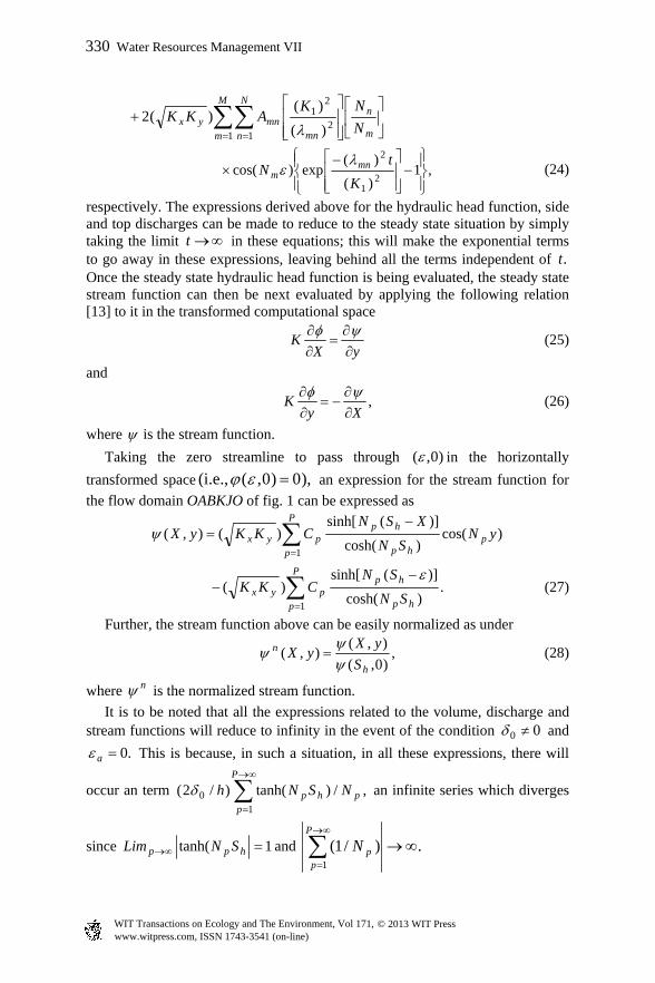
From fig. 3 we see that considerable time may be required for a ponded ditch drainage system to reach steady state, chiefly for situations where drains are being installed relatively deeper in heavy soils having a high anisotropy ratio. The transient state duration has also been observed to be dependent on the spacing between the adjacent drains; among other factors remaining constant, an increase in the ditch spacing increases and a decrease in the ditch spacing decreases this duration. It can further be observed in this figure that both
/ 2topQ Kh and /shalfQ Kh ratios approach to a steady value of 0.742 at large
times, a figure which matches very closely to the corresponding figures of 0.743 and 0.742 obtained from Fukuda [5] and Youngs’ [7] steady state theories. This also serves as an additional check on the rightness of the developed model.
Impervious layer
www.witpress.com, ISSN 1743-3541 (on-line) WIT Transactions on Ecology and The Environment, Vol 171, © 2013 WIT Press
Water Resources Management VII 331
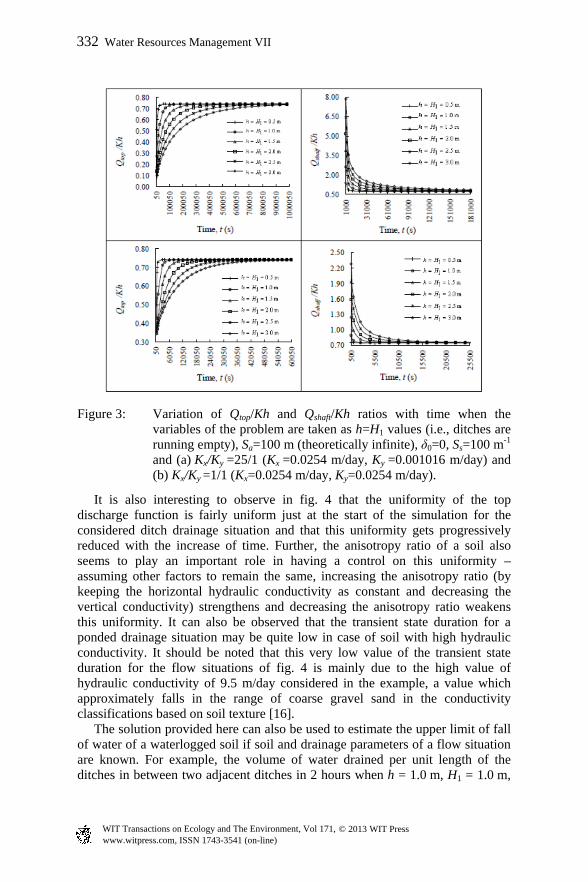
Figure 3: Variation of Qtop/Kh and Qshaft/Kh ratios with time when the variables of the problem are taken as h=H1 values (i.e., ditches are running empty), Sa=100 m (theoretically infinite), δ0=0, Ss=100 m-1 and (a) Kx/Ky =25/1 (Kx =0.0254 m/day, Ky =0.001016 m/day) and (b) Kx/Ky =1/1 (Kx=0.0254 m/day, Ky=0.0254 m/day).
It is also interesting to observe in fig. 4 that the uniformity of the top discharge function is fairly uniform just at the start of the simulation for the considered ditch drainage situation and that this uniformity gets progressively reduced with the increase of time. Further, the anisotropy ratio of a soil also seems to play an important role in having a control on this uniformity – assuming other factors to remain the same, increasing the anisotropy ratio (by keeping the horizontal hydraulic conductivity as constant and decreasing the vertical conductivity) strengthens and decreasing the anisotropy ratio weakens this uniformity. It can also be observed that the transient state duration for a ponded drainage situation may be quite low in case of soil with high hydraulic conductivity. It should be noted that this very low value of the transient state duration for the flow situations of fig. 4 is mainly due to the high value of hydraulic conductivity of 9.5 m/day considered in the example, a value which approximately falls in the range of coarse gravel sand in the conductivity classifications based on soil texture [16]. The solution provided here can also be used to estimate the upper limit of fall of water of a waterlogged soil if soil and drainage parameters of a flow situation are known. For example, the volume of water drained per unit length of the ditches in between two adjacent ditches in 2 hours when h = 1.0 m, H1 = 1.0 m,
www.witpress.com, ISSN 1743-3541 (on-line) WIT Transactions on Ecology and The Environment, Vol 171, © 2013 WIT Press
332 Water Resources Management VII

Figure 4: Variation of top discharge function with distance at the surface of the soil at a few time intervals when the flow parameters of the problem are taken as h=1 m, H1=0.5 m, δ0 =0.2 m, Sa=10 m, Ss=0.001 m-1, εa=0.05 m and Kx/Ky=10/1 (Kx=9.5 m/day, Ky = 0.95 m/day).
m, 20aS m, 05.0a m, 1.00 -1m 001.0sS and m/day 1 yx KK is
0.13164 m3; thus, at the end of 2 hours, the upper limit of fall of water at the surface will be about 6.6 mm ).20/100013164.0( This is an upper limit since,
in reality, with the fall of water level at the surface of the soil with time, the ponding head at the surface will no longer be a constant one but will reduce with the advance of time.
4 Conclusions
An analytical solution has been derived for studying transient dynamics of flow into a network of fully penetrating ditch drains receiving water from a ponded field of uniform depth. The validity of the developed solution has been tested by performing a MODFLOW check on the solution for a specific flow configuration of the ditch drainage problem. The study shows that the transient duration of a ponded ditch drainage situation may last for a considerable period of time for drains in heavy soils, particularly if the anisotropy ratio of the soils is high and the spacing between the adjacent drains as well the depth of the drains are relatively large. Apart from throwing light on the hydraulics of a ponded ditch drainage system in the transient zone, the solution provided here is also important in the sense that it can be utilized to design ditch drains for reclaiming saline and waterlogged areas.
www.witpress.com, ISSN 1743-3541 (on-line) WIT Transactions on Ecology and The Environment, Vol 171, © 2013 WIT Press
Water Resources Management VII 333

References
[1] Ritzema, H.P., Satyanarayana, T.V., Raman, T.V. and Boonstra, J., Subsurface drainage to combat water logging and salinity in irrigated lands in India: Lessons learned in farmer’s field. Agricultural Water Management, 95, pp. 179–189, 2008.
[2] Rao, K.V.G.K. and Leeds-Harrison, P.B. Desalination with subsurface drainage. Agricultural Water Management, pp. 19, 303–11, 1991.
[3] Van Hoorn J.W. and Van Alphen J.G. Salinity control. In H.P. Ritzema, ed. Drainage Principles and Applications, 2nd edition. Wageningen, The Netherlands: International Institute for Land Reclamation and Improvement, Publication 16, pp. 533–600, 1994.
[4] Kirkham, D., Seepage into ditches in the case of a plane water table and an impervious substratum. Trans. Am. Geophys. Union, 31(3), pp. 425–430. 1950.
[5] Fukuda, H., Underdrainage into ditches in soil overlying an impervious substratum. Trans. Am. Geophys. Union, 38(5), 730–739, 1957.
[6] Kirkham, D., Seepage of leaching water into drainage ditches of unequal water level height. J. Hydrol., 3, 207–224, 1965.
[7] Youngs, E.G., Seepage to ditches from a ponded surface. J. Hydrol., 161, pp. 145–154.
[8] Warrick A.W. and Kirkham, D. Two-dimensional seepage of ponded water to full ditch drains. Water Resour. Res., 5(3), pp. 685–93, 1969.
[9] Barua, G. and Tiwari, K.N., Analytical solutions of seepage into ditches from ponded fields. J. Irrig. and Drain. Eng., 121(6), pp. 396–404, 1995.
[10] Chahar, B.R. and Vadodaria G.P. Steady subsurface drainage of ponded surface by an array of parallel ditches. J Hydrologic. Eng., 17(8), pp. 895–908, 2012.
[11] Barua, G. and Alam, W., An analytical solution for predicting transient seepage into ditch drains from a ponded field. Adv. Water Resour., 52, pp. 78–92, 2013.
[12] Kirkham, D. and Powers, W.L., Advanced Soil Physics. Wiley Interscience Inc.: New York, 1972.
[13] Bear, J., Dynamics of fluids in porous media, American Elsevier Publishing Company Inc.: New York, p. 235, 1972.
[14] Chiang, W. and Kinzelbach W., 3D-Groundwater Modeling with PMWIN: a Simulation System for Modeling Groundwater Flow and Pollution. Springer-Verlag; Berlin, 2001.
[15] Maasland, M., Theory of land drainage: Soil anisotropy and land drainage. In: Luthin JN, editor, Drainage of Agricultural Lands, Am. Soc. of Agron., 7, Madison, Wisconsin, 1957.
[16] Oosterbaan, R.J. and Nijland, H.J., Determining the saturated hydraulic conductivity. Drainage Principles and Applications, H.P. Ritzema, ed., 2nd
ed., ILRI Publication 16, Wageningen, The Netherlands, pp. 435–476, 1994.
www.witpress.com, ISSN 1743-3541 (on-line) WIT Transactions on Ecology and The Environment, Vol 171, © 2013 WIT Press
334 Water Resources Management VII