An Analysis of the Size-control and Uniformity of ...
64
An Analysis of the Size-control and Uniformity of Polymeric Nanoparticle Preparation Techniques by Benjamin Ryan Pyle Submitted to the Department of Mechanical Engineering in Partial Fulfillment of the Requirements for the Degree of Bachelor of Science in Mechanical Engineering at the Massachusetts Institute of Technology June 2013 ARGHrV ~ D 2013 Massachusetts Institute of Technology. All rights reserved. Signature of Author: S rnt of Me gineering of May 24, 2013 Certified by: Accepted by: (I Sang-Gook Kim Professor of Mechanical Engineering Thesis Supervisor Anette Hosoi Professor of Mechanical Engineering Undergraduate Officer 1
Transcript of An Analysis of the Size-control and Uniformity of ...
An Analysis of the Size-control and Uniformity of Polymeric NanoparticlePreparation Techniques
by
Benjamin Ryan Pyle
Submitted to theDepartment of Mechanical Engineering
in Partial Fulfillment of the Requirements for the Degree of
Bachelor of Science in Mechanical Engineering
at the
Massachusetts Institute of Technology
June 2013
ARGHrV ~
D 2013 Massachusetts Institute of Technology. All rights reserved.
Signature of Author:S rnt of Me gineeringof May 24, 2013
Certified by:
Accepted by:
(I Sang-Gook KimProfessor of Mechanical Engineering
Thesis Supervisor
Anette HosoiProfessor of Mechanical Engineering
Undergraduate Officer
1

An Analysis of the Size-control and Uniformity of Polymeric NanoparticlePreparation Techniques
by
Benjamin Ryan Pyle
Submitted to the Department of Mechanical Engineeringon May 24, 2013 in Partial Fulfillment of the
Requirements for the Degree of
Bachelor of Science in Mechanical Engineering
ABSTRACT
Nanoparticles are bridge the gap between the micro and atomic scale and have found a variety ofdifferent used, especially in the drug-delivery field. This paper will break down some of the mot
common methods for polymeric nanoparticle production.
Thesis Supervisor: Sang-Gook KimTitle: Professor of Mechanical Engineering
2

ACKNOWLEDGEMENTS
I would like to thank Professor Kim for sticking with me.
3

Table of Contents
Abstract 2
Acknowledgements 3
Table of Contents 4
List of Figures 5
List of Tables 6
1. Introduction 8
1.1. Motivation 8
1.2. Nanoparticle use 9
1.2.1. Quantum dots 9
1.2.2. Drug delivery and imaging 9
1.3. Technical information 10
1.3.1. Polymers 10
1.3.2. Mixtures 11
1.3.3. Diffusion 12
1.3.4. Ostwald ripening 13
1.3.5. Flocculation and precipitation 132. Nanoparticle production 15
2.1. Introduction 15
2.2. Production methods 15
2.2.1. Pyrolysis 16
2.2.2. Stuber process 19
2.2.3. Solvent evaporation 19
2.2.4. Nanoprecipitation 21
2.2.5. Emulsion solvent diffusion 21
2.2.6. Salting out 22
2.2.7. Dialysis 23
2.2.8. Rapid expansion 23
2.2.9. Emulsion polymerization 25
2.2.10. Lost-wax 27
2.2.11. Hydrodynamic flow focusing 29
4

2.2.12. 2D flow focusing 29
2.2.13. 3D flow focusing 32
2.3. Summary 35
3. Analysis of microfluidic nanoparticle synthesis techniques 36
3.1. Introduction 36
3.2. Analysis of production methods 36
3.2.1. Solvent evaporation 36
3.2.2. Nanoprecipitation 40
3.2.3. Emulsion solvent diffusion 42
3.2.4. Salting out 43
3.2.5. Dialysis 36
3.2.6. Rapid expansion 48
3.2.7. Emulsion polymerization 51
3.2.8. Lost-wax 52
3.2.9. 2D flow focusing 54
3.2.10. 3D flow focusing 58
4. Summary and Conclusion 60
5. References 62
5
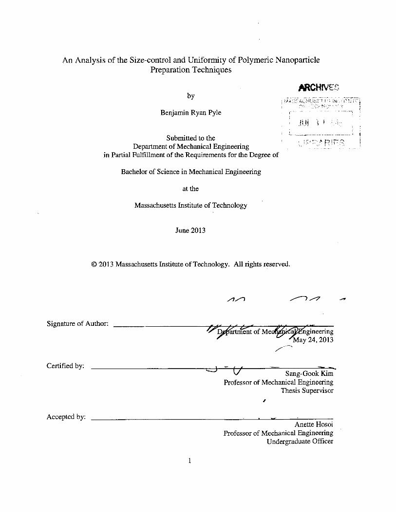
List of Figures
Figure 1:
Figure 2:
Figure 3:
Figure 4:
Figure 5:
Figure 6:
Figure 7:
Figure 8:
Figure 9:
Figure 10:
Figure 11:
Figure 12:
Figure 13:
Figure 14:
Figure 15:
Figure 16:
Figure 17:
Figure 18
Figure 19:
6
Emulsion polymerization
PLGA-PEG nanoparticles by 2D hydrodynamic flow focusing
PLGA-lipid-PEG nanoparticles by 2D hydrodynamic flow focusing
QD-lipid-PEG nanoparticles by 2D hydrodynamic flow focusing
3D microfluidic drifting device
3D thick layer device
Stirring speed and concentration for solvent evaporation
Solvent choice and polymer concentration for solvent evaporation
Images of PLA-lipid nanoparticles
Solvent choice and concentrations for nanoprecipitation
Surfactant concentration for emulsion solvent diffusion
Stirring speed and concentration for salting-out
PLGA nanoparticles produced by dialysis
Images of PTSFT'E nanoparticles produced by rapid expansion
Images of PHDFDA nanoparticles produced by rapid expansion
Images of PPy nanoparticles produced by lost-wax
Flow ratio and concentration for 2D flow focusing
Images of nanoparticles produced by 2D flow focusing
Polymer molecular weight and concentration for 3D flow focusing
26
30
31
32
34
35
37
39
40
41
42
46
48
49
50
53
55
57
58
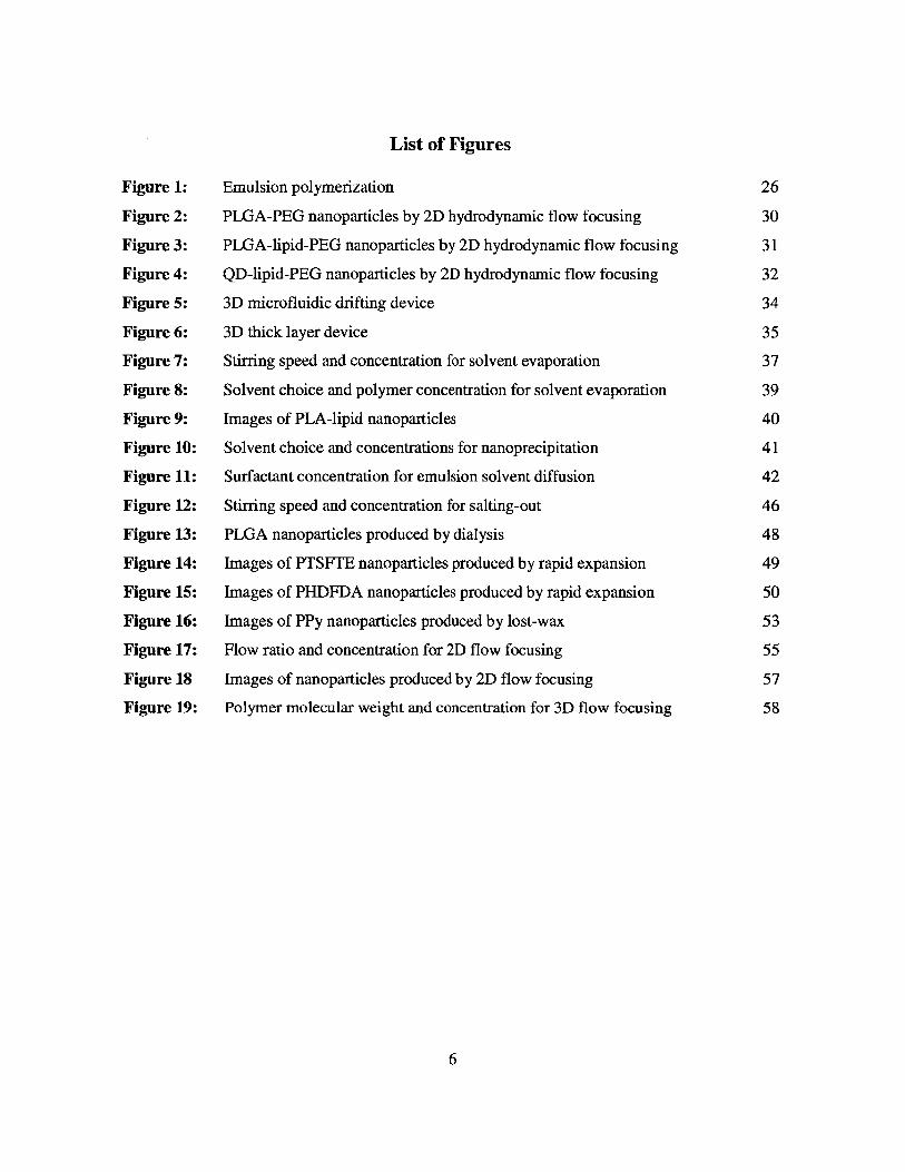
List of Tables
Table 1: PLA nanoparticle size at through emulsion and diffusion 42
Table 2: PLGA nanoparticle size through dialysis 47
Table 3: Summary of methods 60
7
Chapter 1
Introduction
This paper serves to discuss the methods used to produce nanoparticles as well as to
analyze specifically the methods used for production of polymeric nanoparticles. This analysis
was both in terms of uniformity and size-control. Although a variety of methods are discussed,
this paper is not exhaustive. There are an enormous number of different types of nanoparticles
and an even larger variety of ways to produce them. This paper will focus a select group of the
most commonly used methods for polymeric nanoparticle production.
1.1 Motivation for work
Nanoparticles bridge the material property gap between the macro and atomic scale. A
macroscopic material's properties are not size dependent, but the properties of nanoparticles are.
Nanoparticles also have large surface area when compared to the small mass, leading to the
special properties that nanoparticles exhibit. It is possible to suspend nanoparticles made of
certain materials in solutions where larger particulate matter would sink or float. Due to their
unique electrical and optical properties, nanoparticles, such as quantum dots, are finding new
uses in high tech fields while their small size lends them for biological and medical use.
8
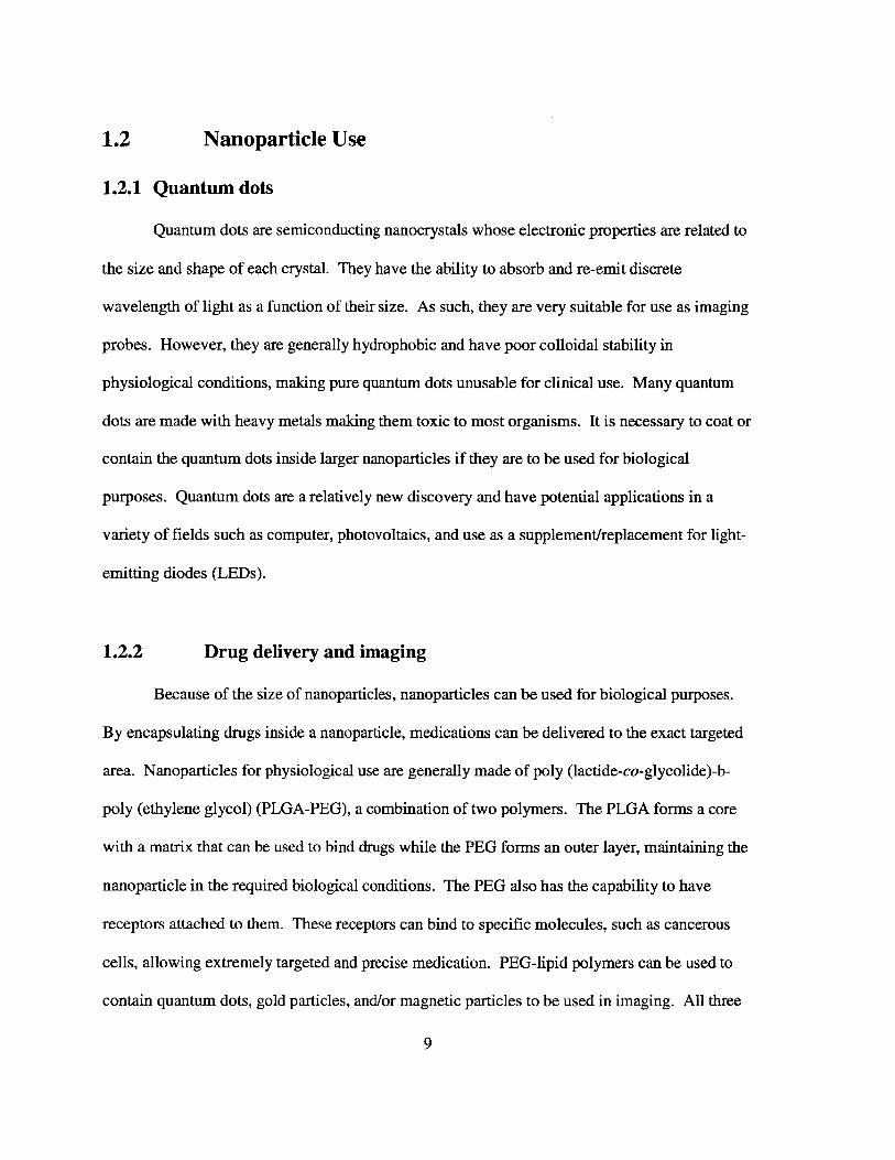
1.2 Nanoparticle Use
1.2.1 Quantum dots
Quantum dots are semiconducting nanocrystals whose electronic properties are related to
the size and shape of each crystal. They have the ability to absorb and re-emit discrete
wavelength of light as a function of their size. As such, they are very suitable for use as imaging
probes. However, they are generally hydrophobic and have poor colloidal stability in
physiological conditions, making pure quantum dots unusable for clinical use. Many quantum
dots are made with heavy metals making them toxic to most organisms. It is necessary to coat or
contain the quantum dots inside larger nanoparticles if they are to be used for biological
purposes. Quantum dots are a relatively new discovery and have potential applications in a
variety of fields such as computer, photovoltaics, and use as a supplement/replacement for light-
emitting diodes (LEDs).
1.2.2 Drug delivery and imaging
Because of the size of nanoparticles, nanoparticles can be used for biological purposes.
By encapsulating drugs inside a nanoparticle, medications can be delivered to the exact targeted
area. Nanoparticles for physiological use are generally made of poly (lactide-co-glycolide)-b-
poly (ethylene glycol) (PLGA-PEG), a combination of two polymers. The PLGA forms a core
with a matrix that can be used to bind drugs while the PEG forms an outer layer, maintaining the
nanoparticle in the required biological conditions. The PEG also has the capability to have
receptors attached to them. These receptors can bind to specific molecules, such as cancerous
cells, allowing extremely targeted and precise medication. PEG-lipid polymers can be used to
contain quantum dots, gold particles, and/or magnetic particles to be used in imaging. All three
9

of these materials provided excellent non-invasive imaging medium, but they are generally toxic.
By encapsulating PEG-lipid polymers in larger nanoparticles, it is possible to safely use the
nanoparticles in physiological imaging. This is the most common use of polymeric
nanoparticles. Almost all of the methods analyzed in this paper can be applied to the creation of
polymeric nanoparticles for drug delivery or imaging.
1.3 Technical information
As nanoparticles, especially polymeric nanoparticles, are almost entirely manufactured in
a solution, it is important to understand the different mechanisms that govern such interactions.
1.3.1 Polymer
A polymer is a chemical compound composed a series of repeating structural units, called
monomers. These monomers come together in a process called polymerization, where they form
into a larger molecule. Monomers are essentially the building blocks used to make the larger
polymer structure. The polymers have distinctive properties that separate them from their
monomer components. Styrofoam or polystyrene is a polymer used in everyday life that is made
from the monomer styrene, an oily liquid at room temperature. Most large biological molecules
are in fact polymers; proteins are polymers of amino acids and nucleic acids (including
deoxyribonucleic acid (DNA) are polymers of nucleotides.
10

1.3.2 Mixtures
When a system contains two or more substances that are mixed, but not chemically
combined, it is referred to as a mixture. There are three types of mixtures based on how well the
components are mixed: solutions, suspensions, and colloids. A solution is a mixture of one
substance completely and uniformly dissolved in another. The substance that is dissolved is
called the solute while the substance doing the dissolving is called the solvent. The degree to
which a solute can dissolve the solvent is called solubility, with a higher solubility meaning it is
easier to form a solution. Common solutions include the air we breathe (a solution of oxygen
and other gasses in nitrogen gas), saltwater, and even metal alloys such as steel (a solution of
mostly iron and carbon) or bronze (a solution of mostly copper and tin). Solutions can be any
combination of the common phases of matter: solid, liquid, and gas. Suspensions are at the
other end of the spectrum, where the two substances are mixed, but there is a clear distinction
between the two substances. The particles are clearly visible and will settle out eventually. An
example of this is sand in water. The water, when rapidly shaken, causes the sand to be
suspended in the water. The water becomes cloudy, but over time, the sand separates out from
the water and forms sediment at the bottom. A colloid lies between a suspension and a solution.
A colloid is a substance that is microscopically dispersed within another substance. Colloids can
occur in any combination of the three phases of matter except for gas-gas as all gasses are
mutually soluble. Some common examples of colloids are milk, styrofoam, and hairspray.
Liquid-liquid colloids, such as milk, are specifically referred to as emulsions. In an emulsion,
one liquid, referred to as the dispersed phase, is dispersed in another, referred to as the
continuous phase. The most common basic example of an emulsion is oil in water, or O/w.
Initially the oil and water will separate into two distinct layers. If the container is shaken, the oil
11
will disperse into tiny droplets throughout the water. Over time, however, these droplets will
eventually aggregate back into one large oil layer as before. This separation occurs because the
emulsion is not stable. Emulsifiers can be added to the emulsion in order to increase the stability
of the emulsion and keep the droplets distinct over prolonged period of time. Emulsifiers are
also referred to as emulsifying agents or stabilizers. A specific type of emulsifier knows as a
surfactant, is commonly used in nanoparticle production. A surfactant, or surface active
substance, is a compound that lowers the surface tension between the two liquids thereby
increasing the stability of the emulsion. These surfactants surround the dispersed droplets and
act as an interface between the two liquids. When a group of surfactant molecules completely
form into a capsule, it is referred to as a micelle.
1.3.3 Diffusion
Diffusion is a phenomenon that results in mass transport and mixing without requiring
bulk motion; that is, mass inside a system will move without needing the entire system to move.
Diffusion is effectively a spreading out of mass. For the purposes of molecules in a solution,
diffusion is the movement of said molecules down concentration gradients; the molecules will
move from areas of higher concentration to areas of lower concentration. Eventually,
equilibrium is reached when all the molecules are effectively spread evenly throughout the
solution.
12
1.3.4 Ostwald ripening
Named after Wilhelm Ostwald, who first described the phenomenon in an article in the
German journal, Allgemeinen Chemie, Ostwald ripening describes how small particles in
solution dissolve then reform as part of a larger particle. This phenomenon is spontaneous as
large particles are more energetically stable than smaller ones. When particles are formed,
molecules come together and bond to each other. Each molecule tries to maximize the number
of bonds it creates with neighboring molecules. This means that the molecules on the inside of
the particle are more stable than those on the outside, as they will have more 'neighbors' to bond
to. Larger particles inherently have more molecules on the inside, bonded to a maximum
number of molecules, than the outside. A system of such particles will move towards a lower,
more stable, energy state over time. As the smaller particles are inertly less stable than the larger
particles, the molecules on the outside of the smaller particles will break off, dissolve into the
solution, and then deposit onto larger particles. Ostwald ripening is the phenomenon that gives
ice cream its texture.
1.3.5 Flocculation and precipitation
Flocculation is the aggregation, or grouping together, of particles in a solution. Over
time, particulate matter will clump together forming flakes called flocs. This is different than the
phenomenon known as precipitation. Precipitation occurs when dissolved particles come out of
the solution and form back into a solid, or precipitate. The main difference is that the particles
that flocculate are not dissolved; they are merely suspended in the solution. As nanoparticles are
so small, the interactions between the surface of the particles and the surrounding solution are
13

able to overcome density effects. While precipitation is used to synthesis nanoparticles,
flocculation is the phenomenon that directly affects them. If the floc floats to the top, the
phenomenon is called creaming while sinking to the bottom is called sedimentation.
14
Chapter 2
Nanoparticle production
2.1 Introduction
Nanoparticles can be made from a variety of different components and can be used in a
wide range of applications. Some of the methods described in this paper refer to distinct
components in their creation; however, they are used to simply illustrate the process in detail.
Materials, temperatures, and time lengths discussed in the context of nanoparticle creation can all
be substituted or adjusted, resulting in nanoparticle formation different than any specific
examples given.
2.2 Production methods
The processes discussed below can be broken down into two main categories, those for
the production of non-polymeric nanoparticles, and those for the production of polymeric
nanoparticles. The non-polymeric nanoparticle production methods discussed in this paper
include pyrolysis and the St6ber process. These two methods are unable to produce non-
polymeric nanoparticles due to the high temperatures associated with pyrolysis and the fact that
the St6ber process only applies to the formation of silica nanoparticles. The other main category,
processes that can create polymeric nanoparticles -which is the focus of this paper-can be
further broken up into two more categories: 'bulk-mixing' and 'continuous flow'. The bulk-
mixing category contains processes that are in batches by, in very simple terms, mixing in a
15

beaker. Of the bulk mixing methods, there is a distinction made between methods that produce
nanoparticles from preformed polymers and those that produce nanoparticles by polymerizing
monomers. The bulk mixing techniques that utilized preformed polymers include solvent
evaporation, nanoprecipitation, emulsion solvent diffusion, salting-out, dialysis, and rapid
expansion. The bulk mixing techniques that produce nanoparticles by polymerizing monomers
include emulsion polymerization and the lost-wax techniques. The continuous flow methods
utilize a continuous stream of solutions through a microfluidic device for the production of
polymers. Both 2D and 3D techniques exist for hydrodynamic flow focusing.
2.2.1 Pyrolysis
Pyrolysis is the breakdown (decomposition) of organic material that occurs at elevated
temperatures in the absence of oxygen. The huge input of energy into the organic material, in
the form of heat, causes it to char, rather than bum (combust) as there is no oxygen to facilitate
combustion. The organic material undergoes both a chemical change and change in physical
phase. Pyrolysis is the process that allows the baking, frying, frilling, and caramelizing of food.
Extreme pyrolysis, or carbonization, is responsible for the transformation of vegetable mater into
fossil fuels.
Cadmium chalcogenide (CdE) nanocrystallites can be produced through pyrolysis (1). A
chalcogen is a chemical element in group 16, or the oxygen family, of the periodic table of
elements. The specific chalcogens that can form nanocrystallites with cadmium (Cd) in this
process are sulfur (S), selenium (Se) and tellurium (Te). In this process, trioctylphosphine oxide
(TOPO) powder is dried and degassed in a reaction vessel. TOPO is a coordinating solvent that
16

makes the growing nanoparticles more soluble, or dissolvable. The drying of the TOPO serves
to rid the powder of any water that may have been absorbed and is achieved by heating the
reaction vessel to ~300' C. The degassing of the TOPO purges the reaction vessel of any oxygen
(which would impede pyrolysis) and any other contaminants. This is done by flooding the
reaction vessel with argon gas (Ar) to effectively push the contaminants out. As it is a noble gas,
Argon is chemically inert, so it does not interfere with most reactions. Argon is chosen over
other noble gasses because it is more inert than nitrogen gas (N 2) while being substantially
cheaper than other noble gasses due to its concentration in the Earth's atmosphere.
A solution of dimethylcadmium (Me2Cd), the source of Cd for the process, and tri-n-
octylphosphine (TOP) is combined with another solution of trioctylphosphine chalcogenide
(TOPE, E = S, Se, Te), the scource of the chalcogen, and more TOP. The reaction vessel
containing TOPO is then removed from the heat, rapidly injected with the Me2Cd, TOPE, and
TOP solution, and vigorously stirred. Bis (trimethylsilyl)/bis (tert-butyldimethylsilyl)
chalcogenide ((TMS) 2E/(BDMS) 2E, E = S, Se, Te) can also be used in place of TOPE. The
reaction vessel is then returned to the heat source, where it is brought back up to a temperature of
approximately 230-260' C. The reaction solution is then left on the heat for a period of hours
while the CdE nanocrystallites are grown. Samples of the solution are periodically drawn out
and tested by analyzing the absorption spectra of the sample to monitor the growth of the
nanocrystallites. If the distribution in nanocrystallite size is increasing, the temperature of the
reaction vessel is lowered. Conversely, if growth appears to have stopped, the temperature is
increased. An extreme micromanagement of the temperature can lead to very monodisperse
nanocrystallites.
17
The nanocrystallites are removed from the reaction solution via flocculation,
centrifugation, and purification. The reaction solution is cooled to approximately 60'C, slightly
higher than the melting point of TOPO (54*C). Anhydrous (without water) methanol is added to
the solution causing the nanocrystallites to flocculate. The nanocrystalline flocculate is then
separated from the remaining liquid via centrifugation; however, it is still not pure enough. The
flocculate is added to anhydrous 1-butanol and centrifuged again. This leaves behind two layers
of solution, one containing the nanocrystallites and the other mostly elemental Cd and
chalcogens. The byproducts are discarded and the reaming nanocrystallite solution is again
mixed with anhydrous methanol, causing flocculation. The flocculate is rinsed with methanol
and vacuum dried, leaving behind only the nanocrystallites.
This method of nanoparticle production allows the extraction of a variety of sized
particles in a single batch by simply removing some fraction of the reaction solution. The rapid
injection of the reactants causes a sudden burst of nucleation of the nanocrystallites. When this
is combined with the temperature drop of the reaction vessel associated with injection, further
nucleation is effectively prevented. This causes all of the nanocrystallites to start growth at the
same time, leading to more monodisperse particles. The nonviolent reheating allows slow,
controllable and consistent growth of the nanocrystallites. Additionally, due to the prevalence of
Ostwald ripening, any small nanocrystallite nuclei that do form after the initial injection are
consumed by the larger particles. While this particular method applies to cadmium
chalcogenide, the same process can be applied to a variety of organometallic precursors.
18
2.2.2 Stober process
The St6ber process is a process for creating monodisperse silicon oxide (SiO2 ), or silica,
nanoparticles discovered by Werner St5ber, Arthur Fink, and Ernst Bohn in 1968 (2). Ammonia
(NH3 ), ethanol, and water are mixed in a flask. Tetraethyl orthosilicate (TOES), the source of Si,
is mixed with the solution. The high pH caused by the NH3 serves to catalyze the reaction.
TOES undergoes a hydrolysis reaction where it reacts with the ambient water to create silicon
tetra hydroxide (Si(OH)4 ) and ethanol. The Si(OH)4 then breaks down into water molecules and
the desired Si0 2 nanoparticles. As the nanoparticles form in the solution, Ostwald ripening
serves to maintain the general monodispersity. The size of the particles created can be controlled
by changing the source and volume ratio of Si and the alcohol used.
2.2.3 Solvent evaporation
Lipid polymer nanoparticles can be synthesized through solvent evaporation (3). PLGA-
lipid-PEG nanoparticles can be made by the addition of an acetonitrile solution of PLGA to an
aqueous solution of lecithin and 1,2-distearoyl-sn-glycero-3-phosphoethanolamine-N-
[amino(polyethylene glycol) (DSPE-PEG). The acetonitrile solution is added to the aqueous
solution and stirred constantly. As the acetonitrile solution is added to the aqueous solution, the
acetonitrile solution is dispersed; however, the concentration of the solvent is still high enough
so that most nanoparticles do not form. The solution is stirred at the elevated temperature for
approximately two hours, which allows most of the acetonitrile to evaporate. As the solvent
begins to evaporate, the PLGA begins to aggregate into nanoparticle cores. The lipids then bind
around this core, creating the complete PLGA-lipid-PEG nanoparticle.
19

As formation of nanoparticles occurs in two different steps; the instantaneous
nanoparticle formation the moment the two solutions mix and the formation occurs of
nanoparticles on the scale of hours as the solvent evaporates, measures need to be taken to ensure
uniform nanoparticle size. The temperature of the aqueous solution can be raised during the
process and serves to break down any non-desired or intermediate nanoparticles. Sonication and
vortex mixing can also be used to ensure both adequate mixing, and monodispersity of the
system. However, without the added energy provided by these measures, the nanoparticles
created by this method are relatively polydisperse due to the two-stage and prolonged
nanoparticle creation. Only a fraction of the lipid and lipid-PEG forms around the PLGA,
resulting in the formation of a variety of nanoparticles including the expected PLGA-lipid-PEG
nanoparticles, liposomes, and pure PLGA nanoparticles.
A modified version of solvent evaporation can be used in the creation of lipid
nanoparticles (4). This method, called melt dispersion, uses the same principles as solvent
evaporation, but on a much shorter time scale. Molten lipids (approximately 65 'C) are added to
an aqueous polymer solution and rapidly stirred, dispersing the lipids throughout the solution.
The solution is then heated back up to ensure the lipids are still in liquid phase and to ensure
nanoparticles have not yet formed. The entire solution is then rapidly cooled to approximately
20'C and stirred. As it cools, the lipids aggregate and nanoparticles are formed. The use of
heating keeps the lipids dissolved without the need for high concentrations of solvent. The time
scale is of the order of minutes rather than hours, so nanoparticles created by melt dispersion are
generally more monodisperse than those created by solvent evaporation.
20

2.2.4 Nanoprecipitation
Nanoprecipitation utilizes solvent displacement through diffusion rather than evaporation
to achieve nanoparticle formation to rapidly create nanoparticles (5-12). The solvent-polymer
solution is added to an aqueous solution. As the solvent polymer interacts with the aqueous
solution, diffusion occurs at the interface of the two solutions. Solvent diffuses into the
surrounding aqueous solution, pulling polymer chains out of the solvent solution. The solvent
diffuses further into the aqueous solution, the concentration of solvent drops low enough to allow
the polymers to aggregate into nanoparticles. Mixing is generally used to disperse the solvent
through the solution. The temperature of the aqueous solution can be raised during the process
and serves to break down any non-desired or intermediate nanoparticles. Sonication and vortex
mixing can also be used to ensure monodispersity of the nanoparticles.
2.2.5 Emulsification-diffusion
Emulsification-diffusion is a modified version of the nanoprecipitation technique that
relies more on emulsification than the evaporation of the solvent (6, 13). Water and a solvent are
mixed together until the solvent is saturated. This solvent solution is then allowed to reach
thermal equilibrium, or a uniform temperature, before the polymer is added to this solution. A
surfactant in an aqueous solution is added to the polymer solution and the new solution is
emulsified by very rapid stirring. The resulting solution is an o/w emulsion with polymer
solution micelles, stabilized by the surfactant, in a surrounding aqueous solution. Additional
water is added to the emulsion which results in the diffusion of the solvent into the water and the
aggregation of the polymer into nanoparticles.
21
2.2.6 Salting-out
The salting-out method of nanoparticle formation is very similar to the emulsification-
diffusion method without the need for a surfactant (6, 14-17). Salting-out is a phenomenon
where an aqueous solution containing water and organic molecules will separate in the presence
of ionic molecules, such as salts. When salts are added to water, they dissolve and split into a
positively charger and a negatively charged molecule. The water molecules surround these ionic
molecules in order to keep them in solution. As more and more ions are present, the water has to
choose between keeping the organic molecules in solution, or the ionic salts. The water will
keep whichever molecules have the high ironic strength in solution, and let the other molecules
separate. This phenomenon can be applied to the creation of nanoparticles. A salting-out agent
(generally a salt, but it can be anything whose ironic strength is stronger than the solvent used),
is dissolved in water which creates a vicious gel. A separate solution of the polymer and a
solvent is made. When a portion of the gel is added to the solvent solution, the water and solvent
do not mix and there are two distinct liquid phases in the solution. Where normally the solvent
would dissolve in the water, the salting-out agent has already consumed that ability. The gel and
solvent are emulsified, creating an o/w emulsion of polymer and solvent micelles in an aqueous
external phase. Further water is added that dilutes the salting-out agent to such an extent that the
water is able to dissolve the solvent. The solvent diffuses into the surrounding water and
nanoparticles aggregate.
22
2.2.7 Dialysis
Another method that can create nanoparticles without the need for a surfactant uses the
principles of dialysis (18). Dialysis is the process of separating molecules in a solution through a
semipermeable membrane. Thesemipermeable membrane only molecules that fit a certain
description (generally size) through. For the creation of nanoparticles, dialysis is used to
displace the solvent from the polymer. A dialysis container is filled with a solvent solution
containing the polymer. The container is then placed in an aqueous environment. As their
concentrations become lower in the surrounding aqueous environment, outside of the dialysis
container, the solvent and polymer want to diffuse out, down the concentration gradient.
However, the polymer molecules are too large to fit through the dialysis semipermeable
membrane, resulting in only the solvent diffusing. Over time, this results in a solvent
concentration drop in the dialysis container to the point that nanoparticles can form.
2.2.8 Rapid Expansion
The rapid expansion technique relies on dissolving the polymer in a supercritical fluid,
rather than an organic solvent. The general need to develop more environmentally friendly
methods of nanoparticle manufacture without such solvent led to the development of the rapid
expansion method (19). A supercritical fluid is a fluid that is at a pressure and temperature
above its critical point. Above the critical point, distinct gas and liquid phases do not exist.
Supercritical fluid typically have properties that lie between the gas and liquid phase of the fluid,
in addition be being good solvents. Some of the most commonly used supercritical fluids are
carbon dioxide end water. For the creation of nanoparticles, the polymer is first dissolved in the
supercritical fluid to the saturation point. The supercritical solution is then isobarically, at a
23

constant pressure, heated to supersaturate the solution. The solution then is allowed to expand
through a nozzle to ambient pressure. This extreme drop in pressure decreases the solubility of
the supercritical fluid, causing the polymers to come out of solution and precipitate into
nanoparticles.
One of the primary drawbacks of rapid expansion is that it produces primarily
microparticles rather than nanoparticles. This is due to the aggregation of the nanoparticles into
larger particle as they exit the nozzle. A modified version of the rapid expansion technique
involves the expansion of the supercritical solution into a liquid solvent, rather than the ambient
air (20). The liquid solvent suppresses particle aggregation, resulting in more monodisperse
nanoparticle formation than those particles created by rapid expansion without the solvent.
Although this sound like it defeats the purpose of the rapid expansion technique, this solvent can
be plain water rather than an organic solvent such as acetonitrile. As the water acts as a weak
solvent, it serves to inhibit some particle aggregation, while still allowing polymer aggregation.
Salt and water solutions can be used in place of pure water to further disrupt the larger particle
aggregation. The improvement results from the increased ionic strength of the aqueous solution.
Although there are a variety of supercritical fluids that can be applied to this technique, these two
rapid expansions techniques have limited application in the formation of nanoparticles due to the
poor solubility of polymers in supercritical fluids.
24
Emulsion polymerization
Unlike the previously discussed methods which relied on the aggregation of preformed
polymers into polymeric nanoparticles, emulsion polymerization relies on the polymerization of
monomers to form polymeric nanoparticles (21). Emulsion polymerization occurs in three
distinct stages or intervals. A monomer is emulsified into an aqueous solution containing a
surfactant. The surfactant stabilizes the monomer and creates relatively large monomer droplets
in the aqueous solution. Smaller monomer droplets form into micelles. Interval I occurs when
an initiator is then added to the solution and reacts with the monomers. The solution is heated
and the monomers grow either by propagation and then enter into micelles, or they become large
enough particles on their own and precipitate form solution. The initiator acts upon the micelles
rather than the large droplet due to the relative surface area of the large droplets when compared
to the larger number of small micelles. Interval II occurs with polymerization within the
micelles. The monomer is fed to sustain the polymerization reaction through diffusion form the
large droplets to the micelles. Monomer continues to disperse out of the large droplets and into
the micelles until all of the monomer droplets are gone. This is referred to as interval III. What
remains are polymeric nanoparticles containing several thousand polymer chains, created from
the micelles or from the deflated large droplets (which have effectively become micelles). A
visualization of the process before and after emulsion polymerization can be seen in Figure 1(a).
25
2.2.9

)
b) 00
Figure 1: A representative diagram of the emulsion polymerization process: (a) conventionalemulsion polymerization, (b) mini-emulsion polymerization, and (c) micro-emulsionpolymerization. Image source (22).
The emulsion polymerization technique relies on the creation of micelles for the
monomer to enter into and polymerize inside. A modified technique, called mini- or nano-
emulsion polymerization, relies on emulsified droplets of monomer rather than a combination of
large monomer droplets with surfactant micelles (22-27). In this technique, monomer is
emulsified in a solution containing a surfactant and initiator and then heated. The initiator then
enters these droplets and starts the polymerization process. A visualization of the process before
and after mini-emulsion polymerization can be seen in Figure 1(b).
A third method of emulsification is called micro-emulsion polymerization. Unlike the
two previous methods of emulsion polymerization, micro-emulsion polymerization is
thermodynamically stable and occurs spontaneously without the need for heating (28). Micro-
emulsions use a relatively high amount of surfactant that creates almost no surface tension
between the monomer droplets and the surrounding aqueous phase. The large concentration of
26

surfactant leads to an abundance of formed micelles. The monomer reacts with the initiator and
enters into the micelles, forming polymer chains. However, due to the large number of micelles,
formation of polymers cannot occur simultaneously. This leads to a continual polymerization
process resulting in nanoparticles consisting of only a small number of polymers. However, due
to the extreme concentration of surfactant, a large number of empty micelles are left behind that
require extra filtering for removal. A visualization of the process before and after micro-
emulsion polymerization can be seen in Figure 1(c).
In order to eliminate the need for a surfactant, a modified version of emulsion
polymerization utilizes ionization to create and maintain an emulsion (29,30). This surfactant-
free emulsion polymerization relies on ionizable initiators or ionic co-monomers. They act in a
similar manner to the salting-out method, where the water molecules keep the ions in solution
rather than the monomer, thus allowing for polymerization and subsequent polymeric
nanoparticle formation.
2.2.10 Lost-wax
The SiO2 nanoparticles created by the strobe process can be used as a mold for further
nanoparticle production. This is accomplished by forming microcrystalline arrays from the SiO 2
nanoparticles (31). These arrays can then be used similar to wax in the lost-wax method of metal
casting (32). In the lost-wax method, a 1:1 scale wax model of the desired final product is first
made. The wax-model is then used to create a mold that is then filled with whatever molten
metal is being cast. To make the SiO 2 mold, nanoparticles are dissolved in ethanol and poured
over a clean microslide. The solution is maintained at room temperature as a single layer of SiO 2
27

film deposits onto the slide through convective assembly. Additional layers can be added by air-
drying the slide then repeating the process with additional SiO 2 ethanol solution of the same
particle size.
The mold of the SiO2 microcrystal structure can be made of a variety of materials,
although polymers are generally the best material. The polymer fills in the voids around the
SiO2 nanoparticles, making an almost perfect mold. The polymer is hardened by a chemical
photochemical reaction or and the SiO 2 is etched away, leaving behind a porous polymer
microstructure. The structure is then filled with nanoparticle precursors which are hardened
using the appropriate process. Finally, the porous polymer mold is removed and the
microcrystalline structure is left behind. The microcrystal can be placed in a solution and
exposed to extended periods (10+ minutes) of sonication, a technique of using sound waves to
cause microbubbles inside the solution to spontaneously form then implode causing shockwaves,
which breaks apart the microcrystal into nanoparticles.
This method can be used for the creation of a wide variety of nanoparticles, including
inorganic, polymeric, metallic solid, core-shell solids, and hollow particles. The determining
factor for if this method can be used is finding a combination of processes that won't destroy: the
SiO2 as the mold is made; the mold as the SiO2 is etched away; the mold as the nanoparticles are
formed and; the nanoparticles as the mold is removed.
28

2.2.11 Hydrodynamic flow focusing
Hydrodynamic flow focusing is a method used to force rapid mixing through
diffusion. At low Reynolds numbers, hydrodynamic flow focusing facilities this diffusion by
'squeezing' a central stream between outer streams that have a higher flow rate. This squeezing
focuses the central stream into a very narrow flow and causes rapid mixing through diffusion
both into and out of the focused stream.
2.2.12 2D flow focusing
The synthesis of polymer based nanoparticles can be accomplished using two
dimensional hydrodynamic flow focusing. PLGA-PEG nanoparticles can be synthesized by
focusing a stream of PLGA-PEG in acetonitrile between two streams of water (10). The
acetonitrile serves as a solvent, keeping the PLGA-PEG polymers separate. Due to the
hydrodynamic flow focusing, rapid mixing of the acetonitrile solution and water occurs. As the
concentration of the acetonitrile decreases, the PLGA-PEG polymers begin to form
nanoparticles. If the mixing time is some degree smaller than the flocculation time of the
nanoparticles, it is expected that the nanoparticles will become more monodisperse. This process
can be seen in Figure 2.
29

(a)
(c) .
Figure 2: The synthesis of PLGA-PEG nanoparticles by 2D hydrodynamic flow focusing.(a) A
microfluidic device that uses two streams of water to focus an acetonitrile solution into a narrow
stream. (b) The small width of the focused stream allows the creation of nanoparticles due to
diffusion. Rapid mixing is achieved by both the diffusion of water into the focused stream and
the diffusion of the acetonitrile solvent out of the stream. (c) A representation of the ideal
nanoparticle structure created from this method. Image source (10).
Homogenous nanoparticles created using hydrodynamic focused flow can be attained by
maximizing the rate the streams mix. Additional features can be added to the microfluidic
device that helps to minimize mixing time (11). One type of such feature that can be added to
the microfluidic channel is micromixing structures. Generally, these structures consist of sharp
turns and geometries that rely on the fluid's inertia to achieve a rate of mixing beyond that of
pure diffusion through convective effects. The gains in mixing time reduction caused by these
features allow the production of more complicated nanoparticles than the solvent displacement
method while still maintaining a single-step process.
Lipid-polymer nanoparticles can be produced using the improved inertial mixing
provided by the modified hydrodynamic flow focusing technique. PGLA-lipid-PEG
nanoparticles can be synthesized by focusing a stream of PGLA dissolved in acetonitrile between
30
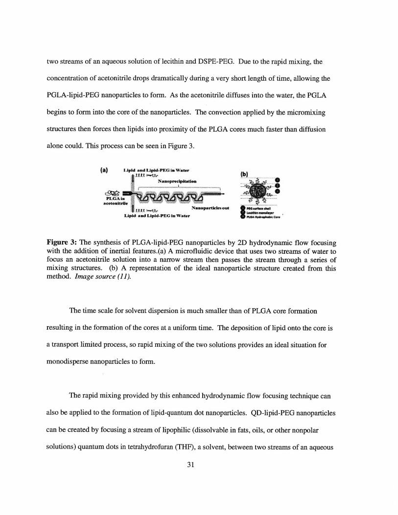
two streams of an aqueous solution of lecithin and DSPE-PEG. Due to the rapid mixing, the
concentration of acetonitrile drops dramatically during a very short length of time, allowing the
PGLA-lipid-PEG nanoparticles to form. As the acetonitrile diffuses into the water, the PGLA
begins to form into the core of the nanoparticles. The convection applied by the micromixing
structures then forces then lipids into proximity of the PLGA cores much faster than diffusion
alone could. This process can be seen in Figure 3.
(a) irpk and LIptd-PE u I* waterN....
.... ..
Figure 3: The synthesis of PLGA-lipid-PEG nanoparticles by 2D hydrodynamic flow focusingwith the addition of inertial features.(a) A microfluidic device that uses two streams of water tofocus an acetonitrile solution into a narrow stream then passes the stream through a series ofmixing structures. (b) A representation of the ideal nanoparticle structure created from thismethod. Image source (11).
The time scale for solvent dispersion is much smaller than of PLGA core formation
resulting in the formation of the cores at a uniform time. The deposition of lipid onto the core is
a transport limited process, so rapid mixing of the two solutions provides an ideal situation for
monodisperse nanoparticles to form.
The rapid mixing provided by this enhanced hydrodynamic flow focusing technique can
also be applied to the formation of lipid-quantum dot nanoparticles. QD-lipid-PEG nanoparticles
can be created by focusing a stream of lipophilic (dissolvable in fats, oils, or other nonpolar
solutions) quantum dots in tetrahydrofuran (THF), a solvent, between two streams of an aqueous
31
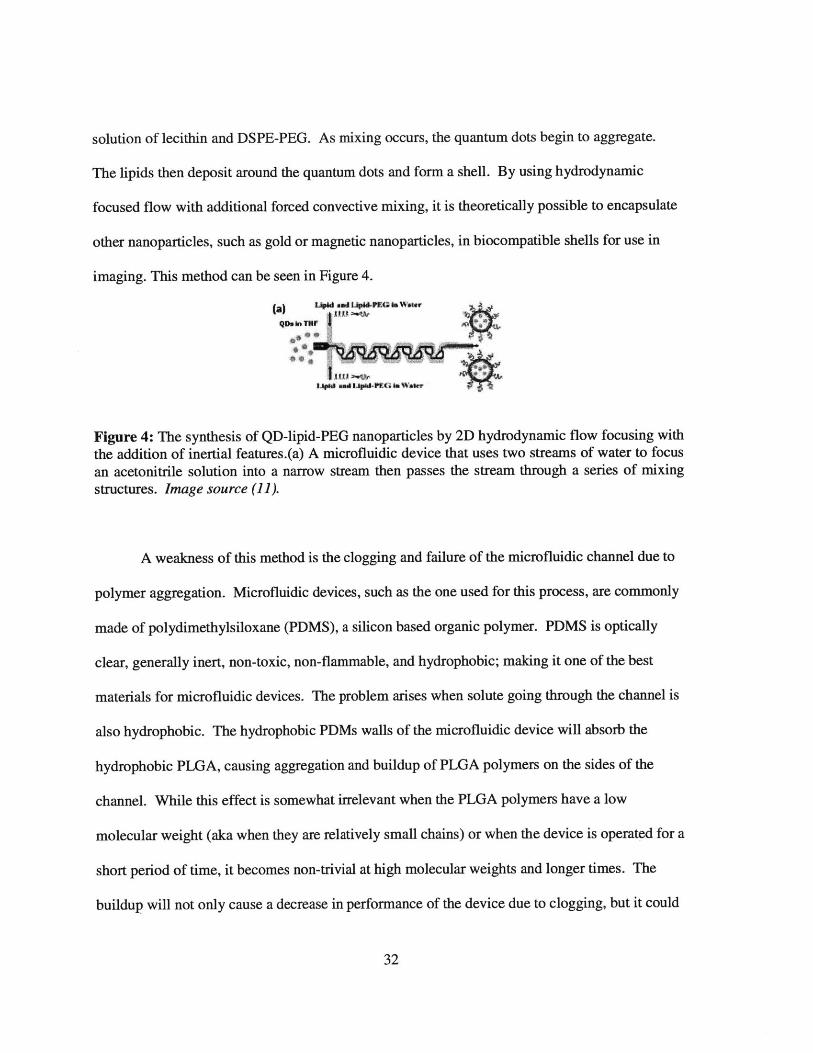
solution of lecithin and DSPE-PEG. As mixing occurs, the quantum dots begin to aggregate.
The lipids then deposit around the quantum dots and form a shell. By using hydrodynamic
focused flow with additional forced convective mixing, it is theoretically possible to encapsulate
other nanoparticles, such as gold or magnetic nanoparticles, in biocompatible shells for use in
imaging. This method can be seen in Figure 4.
1.a) u Lp d aI4P.G is Watr
'QD* In TUF
Figure 4: The synthesis of QD-lipid-PEG nanoparticles by 2D hydrodynamic flow focusing with
the addition of inertial features.(a) A microfluidic device that uses two streams of water to focus
an acetonitrile solution into a narrow stream then passes the stream through a series of mixing
structures. Image source (11).
A weakness of this method is the clogging and failure of the microfluidic channel due to
polymer aggregation. Microfluidic devices, such as the one used for this process, are commonly
made of polydimethylsiloxane (PDMS), a silicon based organic polymer. PDMS is optically
clear, generally inert, non-toxic, non-flammable, and hydrophobic; making it one of the best
materials for microfluidic devices. The problem arises when solute going through the channel is
also hydrophobic. The hydrophobic PDMs walls of the microfluidic device will absorb the
hydrophobic PLGA, causing aggregation and buildup of PLGA polymers on the sides of the
channel. While this effect is somewhat irrelevant when the PLGA polymers have a low
molecular weight (aka when they are relatively small chains) or when the device is operated for a
short period of time, it becomes non-trivial at high molecular weights and longer times. The
buildup will not only cause a decrease in performance of the device due to clogging, but it could
32

also lead to a buildup of pressure and device failure. This is especially prevalent when higher
concentrations of PLGA or higher molecular weight PLGA polymers (longer chains) are used.
The ability to make nanoparticles out of a variety of PLGA molecular weights is ideal for fine
tuning of drug release. The buildup of PLGA on the walls of the channel can be mitigated by
coating the channel with special materials, but this process is much more labor and time
intensive than a standard, pure PDMS device.
2.2.13 3D flow focusing
In order to maintain solvency and prevent hydrophobic polymer aggregation on the
PDMS walls, it is possible to add another pair of sheaths above and below the focused stream,
thus focusing the stream into a line-esque flow, rather than a column. The challenge with three
dimension flow focusing is the mechanism in which nanoparticles are formed, solvent
displacement. In two dimension flow focusing, the nanoparticles form as the solvent is dispersed
into the aqueous side sheaths. If the additional sheaths used in three dimensional flow focusing
are to be of the same aqueous solution as the conventional sheaths used in two dimensional
focusing, they must be applied at the same point. Non-planar microfluidic devices can be made
that sheath and focus the stream at one point, thus solving that problem. However, these devices
are considerably more complicated to fabricate using photolithography, the traditional method of
solidifying PDMS using controlled exposure to light rays, and cost much more than the simple,
planar microfluidic device used in two dimensional focusing. Another approach to keep the
microfluidic device planar and relatively inexpensive is to apply the focusing in two steps, one to
focus the stream vertically (out of plane) and the other to focus the stream horizontally (as is
done in the two dimensional focusing). The polymer-solvent solution would first be focused in
33

one direction by another solvent solution, and then focused in the other by the anti-solvent
solution where the nanoparticles would begin to form.
One method used to accomplish this uses 'microfluidic drifting' (33). As seen in Figure
5, the polymer-solvent solution enters the device alongside another solvent solution. These two
streams of solvent solution then undergo a 90 degree turn at a relatively large radius, which
focuses the polymer-solvent solution vertically. This is achieved through lateral movement of
the polymer-solvent solution induced by the centrifugal effect of the turn. The conventional
method of two dimensional flow focusing is then applied. The vertically focused stream is
sheathed horizontally between two aqueous streams where diffusion of the solvent is achieved.
Solvent diffusion causes nanoparticle formation and the additional vertical focusing prevents
hydrophobic polymer aggregation on the walls. However, microfluidic drifting can only be
achieved at high Reynolds numbers and relatively low polymer-solvent flow rates. This can
cause the polymer-solvent to become diluted by the solvent sheath and lower throughput.
Vedl ftcusing
Sample
Hrizontal
- (~ree~ M)
4.5E.
- E-5
2.5E0 SE-
Figure 5: A 3D hydrodynamic flow focusing device that uses microfluidic drifting.(a) The bendin the device applies vertical focusing to the red stream while a conventional pair of sheathsprovides the horizontal focusing. Image source (33).
34

Another method accomplishes three dimensional flow focusing at lower Reynolds
numbers and higher flow rates through the use of a very thick single layer (12). As seen in Figure
6, a wide channel with three sequential vertical inlets provides the vertical flow focusing while
the conventional two dimensional structures provide the horizontal focusing. Solvent solutions
enter through the first and third vertical inlet, sandwiching the polymer-solvent solution that
enters through the second inlet. As these two sheaths are still solvent solutions, the polymer
stays dissolved. The vertically focused stream is then horizontally focused by two aqueous
streams. This method prevents hydrophobic polymer buildup on the walls and functions at
relatively high flow rates.
Figure 6: A 3D hydrodynanmic flow focusing device that uses three sequential inlets.(a) Thethree sequential inlets provide the vertical flow focusing while a conventional pair of sheathsprovides the horizontal focusing. Image Source (12).
2.3 Summary
Once the nanoparticles are synthesized, they need to be made ready for use. Unless
otherwise stated, the nanoparticles get purified of any reaming solvents or byproducts by
centrifugation, filtration, or dialysis. Once cleansed, the nanoparticles become resuspended in
another solution, typically water. Here, they are ready for immediate use or they can be frozen
or freeze-dried for later use.
35
Chapter 3
Analysis of polymeric nanoparticle production methods
3.1 Intro
As previously stated, there are numerous varieties of polymeric nanoparticles that can be created
from an equally large number of methods. A select few cases of each method will be analyzed
for nanoparticle uniformity and size-control. Cases were selected based off the type of
polymeric nanoparticle created, so as to have a means of comparison; however, each case is
unique in its own way and cases were not found that used the same precursors for all methods.
Additionally, the majority of the cases created polymeric nanoparticles with drugs loaded inside
of them. It was observed that the specific drug loaded into the nanoparticle did not play a large
role in the size of the resulting nanoparticles when compared to the factors specifically discussed
below. For that reason, the drugs are not going to be discussed.
3.2 Analysis of production methods
3.2.1 Solvent evaporation
Zhang, et al. reported on the production of poly (trimethylene carbonate) (PTMC) and
monomethoxy poly(ethylene glycol)-block-poly(trimethylene carbonate) (mPEG-PTMC)
nanoparticles using the solvent evaporation method (16). For the production of PTMC, an
aqueous solution of 2% by weight poly (vinyl alcohol) (PVA) was created. A separate
dichloromethane (DCM) organic solution containing 1 to 4% by weight of PTMC was also
created. 20 milliliters (mL) of the aqueous solution was added to 7.5 mL of the organic solution
36

under vigorous stirring at 6,500 to 24,000 revolutions per minute (rpm). An additional 30 mL of
.5% by weight PVA in water is added and stirred at 600 rpm for 30 seconds. The stirring was
continued for an hour and the emulsion left at room temperature. As the DCM evaporates, the
PTMC nanoparticles form. The PTMC nanoparticles produced form this method were 316±3nm
in diameter with a polydispersity index of .13. mPEG-PTMC nanoparticles can be created using
the name method minus the PVA as the mPEG-PTMC is self-stabilizing. The mPEG-PTMC
nanoparticles produced from this method were 110±5nm in diameter with a polydispersity index
of .13.
A1200 .
'0.961000-
Soo.
~600W.9
~400. 0.17
200
015000 10000 15000 20000 25000
Stirrng ed (rpm)B
450 - -0.12
40D0
0.160.17
0.15
20
10
Conenraion (vl%)
Figure 7: The effect of (a) stirring speed and (b) PTMC concentration on mPEG-PTMCnanoparticle size. The polydispersity index is shown above each data point. Image Source (16).
As seen in Figure 7, the size of the PTMC nanoparticles can be controlled by the
concentration of the PTMC in the DCM solution along with the speed at which the two solutions
37
are emulsified. PTMC nanoparticles of sizes ranging from 285 to 426 nm were formed by
adjusting these factors. At emulsion speeds lower than 13,500 rpm, the polydispersity of the
PTMC molecules skyrockets to 0.96, meaning that the created PTMC nanoparticles are almost
completely heterogeneous. The average size of the PTMC nanoparticles also drastically
increases at low speeds to longer than 1,000 nanometers (nm) in length. Noticeably, the mPEG-
PTMC nanoparticles were not nearly as affected by the concentration and stirring speed, always
falling between 95 and 120 nm in diameter.
Chan, et al., reported on the production PLGA-lecithin-PEG core-shell nanoparticles using
the solvent evaporation method (3). First, PLGA with a 50:50 monomer ratio was dissolved in a
solvent at varying concentrations, creating an organic solution. 20 percent of the PGLA
polymer's weight worth of lecithin and 1,2-distearoylsn-glycero-3-phosphoethanolamine-N-
carboxy(polyethylene glycol)2000 (DPSE-PEG-COOH), in a 7:3 molar ratio, was dissolved in an
aqueous solution containing four percent ethanol. This solution was then heated to 65*C as to
keep the lecithin in a liquid state. The organic solution was then added to the heated aqueous
solution dropwise at a rate of one mUmin under gentle stirring. After all of the organic solution
is added, the solution is vortexed for three minutes hollowed by two hours of gentle stirring at the
elevated temperature. Over this time, the solvent evaporated, causing PLGA-lecithin-PEG
nanoparticles to form. Dimethylformamide, acetone, acetonitrile, and THF were all used in
varying concentrations as solvents for this process.
38

A 220200
- 180E 1 mg/mlc 160
140 U 2 mg/ml1205100 a 5 Mg/Ml
S80-8 10 mg/mi
60-
40- m 25 mg/ml20-
0
DMF Acetone Acetonitrile THF
Figure 8: The effect of PLGA concentration and choice of solvent on PLGA-lecithin-PEGnanoparticle size. Image Source (3).
As seen in Figure 8, the size of the PLGA-lecithin-PEG nanoparticles can be controlled
by the concentration of the PLGA polymer in the organic solution along with the organic solvent
used in said solution. It was observed that the higher the concentration of PLGA used, the larger
the created nanoparticles were, across all used solvents. Additionally, a trend towards larger
nanoparticle formation was observed as the solvent used became less water miscible. The very
non-polar solvent THF produced nanoparticles with a relatively low polydispersity
(approximately 0.100) and larger diameters (100-220 nm); while the very polar solvent DMF
produced nanoparticles with relatively high polydispersity (approximately .3) and smaller
diameters (40-120nm).
39
3.2.2 Nanoprecipitation*
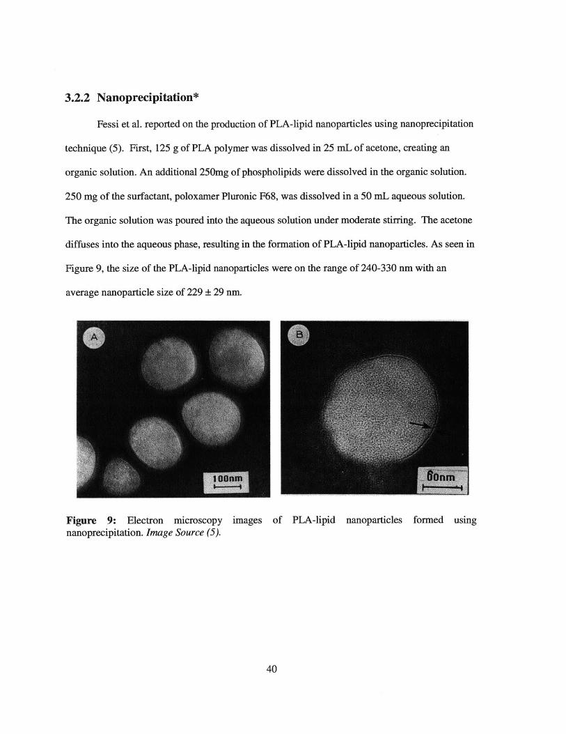
Fessi et al. reported on the production of PLA-lipid nanoparticles using nanoprecipitation
technique (5). First, 125 g of PLA polymer was dissolved in 25 mL of acetone, creating an
organic solution. An additional 250mg of phospholipids were dissolved in the organic solution.
250 mg of the surfactant, poloxamer Pluronic F68, was dissolved in a 50 mL aqueous solution.
The organic solution was poured into the aqueous solution under moderate stirring. The acetone
diffuses into the aqueous phase, resulting in the formation of PLA-lipid nanoparticles. As seen in
Figure 9, the size of the PLA-lipid nanoparticles were on the range of 240-330 nm with an
average nanoparticle size of 229 29 nm.
Figure 9: Electron microscopy images of PLA-lipid nanoparticles formed usingnanoprecipitation. Image Source (5).
40

Cheng et al. reported on the production of PLGA-PEG nanoparticles using
nanoprecipitation technique (8). First, PLGA-PEG polymer was dissolved at in various solvents,
creating an organic solution. The organic solution was added dropwise to twice its volume worth
of water. The solvent diffuses into the aqueous phase, resulting in the formation of PLA-lipid
nanoparticles. The solvent:water ratio was varied from 1:10 to 1:1 with a constant PLGA-PEG
polymer concentration of 10mg/mL in the organic solution. The PLGA polymer concentration I
the organic solution was also varied from 5 to 50 mg/mL with a constant solvent:water ratio of
1:2.
DMF Milo DMF
A s n Fg e ,0 mgsmuCUFJ AOMuMziI 60 M"ti
C
0 50 100 150 200 250 200 260 0 60 100- 150 2D0 260 300 WO0(A)p~f taiiucs airM fBin NU1IopwOM am 0m~f)
Figure 10: The effect of solvent choice, (a) solvent:water ratio, and (b) polymer concentrationon PLGA-PEG nanoparticle size. Image Source (8).
As seen in Figure 10, the size of the PLGA -PEG nanoparticles can be controlled by the
choice of solvent, the solvent:water ratio, and the polymer concentration in the organic solution.
It was observed that the lower the solvent:water ratio was, the larger the created nanoparticles
were, across most used solvents. Furthermore, the higher the concentration of PLGA-PEG
polymer was, the larger the created nanoparticles were, across all used solvents Additionally, a
trend towards larger nanoparticle formation was observed as the solvent used became less water
miscible.
41
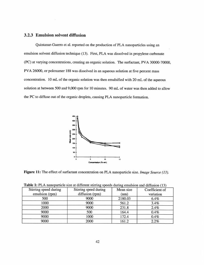
3.2.3 Emulsion solvent diffusion
Quintanar-Guerro et al. reported on the production of PLA nanoparticles using an
emulsion solvent diffusion technique (13). First, PLA was dissolved in propylene carbonate
(PC) at varying concentrations, creating an organic solution. The surfactant, PVA 30000-70000,
PVA 26000, or poloxamer 188 was dissolved in an aqueous solution at five percent mass
concentration. 10 mL of the organic solution was then emulsified with 20 mL of the aqueous
solution at between 500 and 9,000 rpm for 10 minutes. 90 mL of water was then added to allow
the PC to diffuse out of the organic droplets, causing PLA nanoparticle formation.
E
100
50
0 0 . 15
Figure 11: The effect of surfactant concentration on PLA nanoparticle size. Image Source (13).
Table 1: PLA nanoparticle size at different stirring speeds during emulsion and diffusion (13)Stirring speed during Stirring speed during Mean size Coefficient of
emulsion (rpm) diffusion (rpm) (nm) variation500 9000 2180.03 6.4%1000 9000 561.2 3.4%2000 9000 231.8 2.4%9000 500 164.4 0.4%9000 1000 172.4 0.4%9000 2000 161.2 2.2%
42
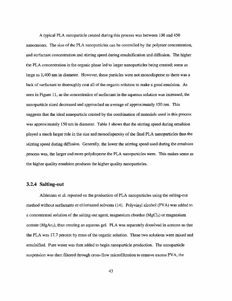
A typical PLA nanoparticle created during this process was between 100 and 450
nanometers. The size of the PLA nanoparticles can be controlled by the polymer concentration,
and surfactant concentration and stirring speed during emulsification and diffusion. The higher
the PLA concentration in the organic phase led to larger nanoparticles being created; some as
large as 1,400 nm in diameter. However, these particles were not monodisperse as there was a
lack of surfactant to thoroughly coat all of the organic solution to make a good emulsion. As
seen in Figure 11, as the concentration of surfactant in the aqueous solution was increased, the
nanoparticle sized decreased and approached an average of approximately 150 nm. This
suggests that the ideal nanoparticle created by the combination of materials used in this process
was approximately 150 nm in diameter. Table 1 shows that the stirring speed during emulsion
played a much larger role in the size and monodispersity of the final PLA nanoparticles than the
stirring speed during diffusion. Generally, the lower the stirring speed used during the emulsion
process was, the larger and more polydisperse the PLA nanoparticles were. This makes sense as
the higher quality emulsion produces the higher quality nanoparticles.
3.2.4 Salting-out
Allemann et al. reported on the production of PLA nanoparticles using the salting-out
method without surfactants or chlorinated solvents (14). Polyvinyl alcohol (PVA) was added to
a concentrated solution of the salting-out agent, magnesium chordae (MgCl 2) or magnesium
acetate (MgAc 2), thus creating an aqueous gel. PLA was separately dissolved in acetone so that
the PLA was 17.7 percent by mass of the organic solution. These two solutions were mixed and
emulsified. Pure water was then added to begin nanoparticle production. The nanoparticle
suspension was then filtered through cross-flow microfiltration to remove excess PVA, the
43

salting-out agent, and acetone. PLA nanoparticles produced using this method were typically
between 250 and 450 nm in diameter depending on the specific salting-out agent used with
concentrations of PVA ranging between 10 percent and 12 percent. The study does not report on
the monodispersity of the PLA nanoparticles, but it is noted that the size of the PLA
nanoparticles increases with lower PLA concentrations, up to a maximum reported nanoparticle
diameter of 735 nm.
Perugini et al. reported on the production of PLGA nanoparticles using salting-out
method (15). PVA was added to a concentrated solution of calcium chloride (CaCl2 ), the salting-
out agent, thus creating an aqueous gel. PLGA was separately dissolved in acetone so that the
PLGA was 2.5 percent by weight of the organic solution. The aqueous solution was added to the
organic solution under vigorous stirring at 13,500 rpm. Further PVA solution was added so that
there was a 1:2 weight ratio of the PLGA solution to the PVA solution and an o/w emulsion was
formed. Pure water was added dropwise to the emulsion, causing the acetone to diffuse into the
surrounding aqueous solution, and enabling the production of PLGA nanoparticles. The
nanoparticles were then purified, either by centrifugation or a combination of dialysis and
centrifugation. PLGA nanoparticles produced by this method were typically between 480 nm to
55,550 nm depending on the concentration of PVA and CaCl2 . The smallest nanoparticles
created used a relatively large concentration of CaCl2 and a relatively low concentration of PVA.
However, the opposite combination, low CaC12 and high PVA, was not the largest particle
created through this method, suggesting a simple correlation between either of these two factors
to nanoparticle size is not the case. The uniformity of size, although not specifically commented
44

on, is seen to be quite low, where the smallest batch reported had 20 percent of the total
nanoparticles smaller than 480 nm or larger than 2,050 nm.
Zhang et al. reported on the production of poly (trimethylene carbonate) (PTMC) and
monomethoxy poly (ethylene glycol)-block-poly (trimethylene carbonate) (mPEG-PTMC)
nanoparticles using the salting-out method (16). For the production of PTMC, an aqueous
solution of 60 percent by weight magnesium chloride hexahydrate (MgCl 2*-6H 2O) and 2 percent
by weight PVA. A separate organic THF solution containing 1 to 4 percent by weight of PTMC
was also created. 10 mL of the aqueous solution was added to 5.5 mL of the organic solution
under vigorous stirring at 6,500 to 24,000 rpm. An additional 10 mL of .5 percent by weight
PVA in water is added and stirring maintained for 30 second. As this water is added, the THF
diffuses out of the organic phase and the PTMC nanoparticles can form. The PTMC
nanoparticles produced form this method were 1811nm in diameter with a polydispersity index
of .17. mPEG-PTMC nanoparticles can be created using the name method minus the PVA as the
mPEG-PTMC is self-stabilizing. The mPEG-PTMC nanoparticles produced from this method
were 113±1nm in diameter with a polydispersity index of .19.
45

A1200
1000-
800-
u. 600
~4W-
200 0.080.14 0.11
05"0 100 100 200 2M
S11Tfng Weed(rm)
B450
400-
s 350-
*300-
250 0.09 .14
0.16 0.11 . - ~
150-
Comentrain (vtl>
Figure 12: The effect of (a) stirring speed and (b) PTMC concentration on mPEG-PTMC
nanoparticle size. The polydispersity index is shown above each data point. Image Source (16).
The size of the PTMC nanoparticles can be controlled by the concentration of the PTMC
in the THF solution along with the speed at which the two solutions are emulsified. PTMC
nanoparticles of sizes ranging from 183 to 251 nm were formed by adjusting these factors.
Noticeably, the mPEG-PTMC nanoparticles were not nearly as affected by the concentration and
stirring speed, always falling between 95 and 120 nm in diameter.
3.2.5 Dialysis
Jeong et al. reported on the production of PLGA nanoparticles using the dialysis method
without surfactants or emulsifiers (18). 20 mg of PLGA was dissolved in lOmL of different
solvents, creating an organic solution. The solvents used in the experiment include
46
dimethylsulfoxide (DMSO), DMF, dimethylacetamide (DMAc), THF, and acetone. The organic
solution was kept at room temperature and stirred until the PLGA was completely dissolved in
the solvent. The organic solution was added to dialysis constrainer with molecular cutoff of
12,000g/mol (the smallest PLGA molecule used has a number-average molecular weight of
30,200 g/mol). The solution was dialyzed against 1.0 L of distilled water three times for three
hours each, with the water being replaced after each period. The sizes of the PLGA
nanoparticles produced through this dialysis method can be seen in Table x, below.
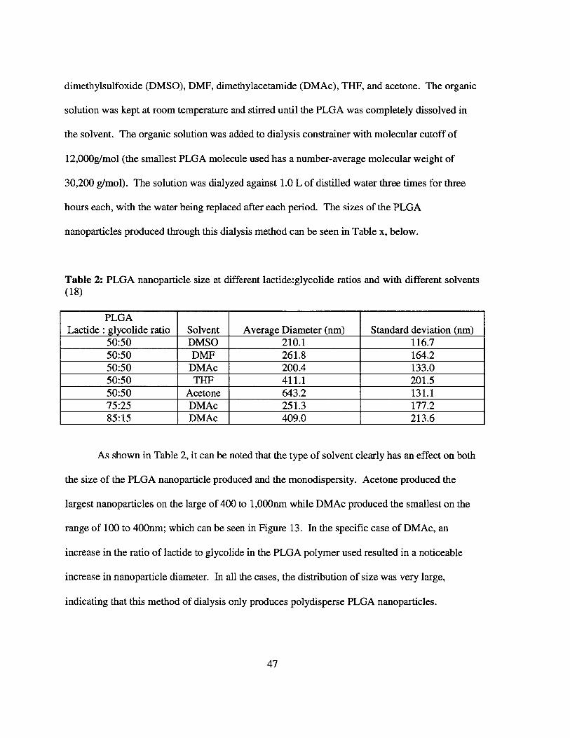
Table 2: PLGA nanoparticle size at different lactide:glycolide ratios and with different solvents(18)
PLGALactide : glycolide ratio Solvent Average Diameter (nm) Standard deviation (nm)
50:50 DMSO 210.1 116.750:50 DMF 261.8 164.250:50 DMAc 200.4 133.050:50 THF 411.1 201.550:50 Acetone 643.2 131.175:25 DMAc 251.3 177.285:15 DMAc 409.0 213.6
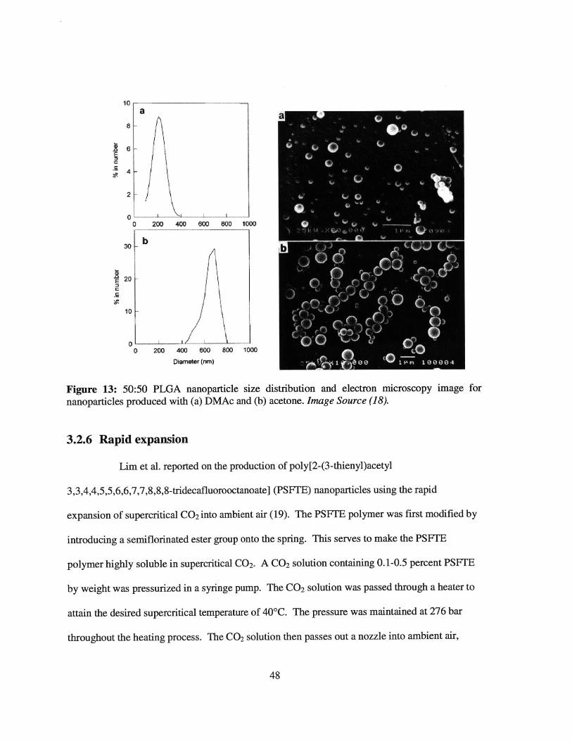
As shown in Table 2, it can be noted that the type of solvent clearly has an effect on both
the size of the PLGA nanoparticle produced and the monodispersity. Acetone produced the
largest nanoparticles on the large of 400 to 1,000nm while DMAc produced the smallest on the
range of 100 to 400nm; which can be seen in Figure 13. In the specific case of DMAc, an
increase in the ratio of lactide to glycolide in the PLGA polymer used resulted in a noticeable
increase in nanoparticle diameter. In all the cases, the distribution of size was very large,
indicating that this method of dialysis only produces polydisperse PLGA nanoparticles.
47
10a a
4
2
0o 200 400 600 800 1000
I0 I - l
20 ,/10
o zoo 400 O 800 1000 O
Figure 13: 50:50 PLGA nanoparticle size distribution and electron microscopy image fornanoparticles produced with (a) DMAc and (b) acetone. Image Source (18).
3.2.6 Rapid expansion
Lim et al. reported on the production of poly[2-(3-thienyl)acetyl
3,3,4,4,5,5,6,6,7,7,8,8,8-tridecafluorooctanoate] (PSF'E) nanoparticles using the rapid
expansion of supercritical CO 2 into ambient air (19). The PSFTE polymer was first modified by
introducing a semiflorinated ester group onto the spring. This serves to make the PSFTE
polymer highly soluble in supercritical CO 2. A CO2 solution containing 0.1-0.5 percent PSFTE
by weight was pressurized in a syringe pump. The CO2 solution was passed through a heater to
attain the desired supercritical temperature of 40'C. The pressure was maintained at 276 bar
throughout the heating process. The CO2 solution then passes out a nozzle into ambient air,
48
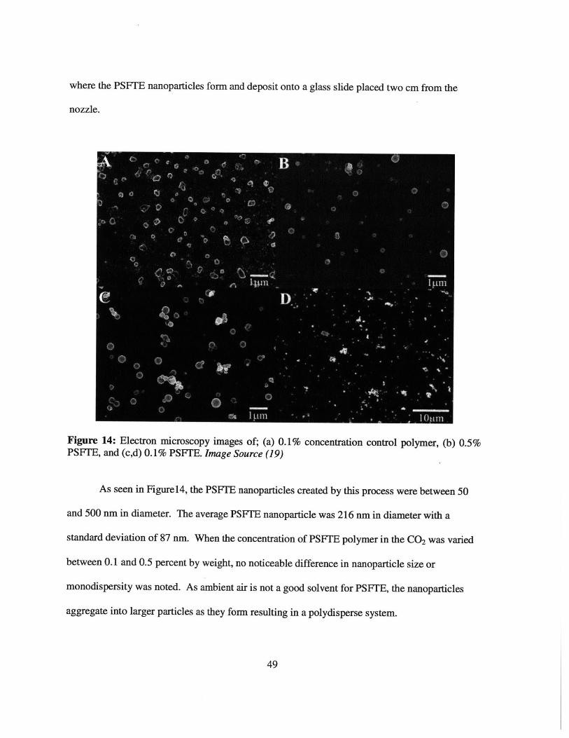
where the PSFTE nanoparticles form and deposit onto a glass slide placed two cm from the
nozzle.
Figure 14: Electron microscopy images of; (a) 0.1% concentration control polymer, (b) 0.5%PSFTE, and (c,d) 0.1% PSF1E. Image Source (19)
As seen in Figurel4, the PSFTE nanoparticles created by this process were between 50
and 500 nm in diameter. The average PSFTE nanoparticle was 216 nm in diameter with a
standard deviation of 87 nm. When the concentration of PSFTE polymer in the CO2 was varied
between 0.1 and 0.5 percent by weight, no noticeable difference in nanoparticle size or
monodispersity was noted. As ambient air is not a good solvent for PSFTE, the nanoparticles
aggregate into larger particles as they form resulting in a polydisperse system.
49
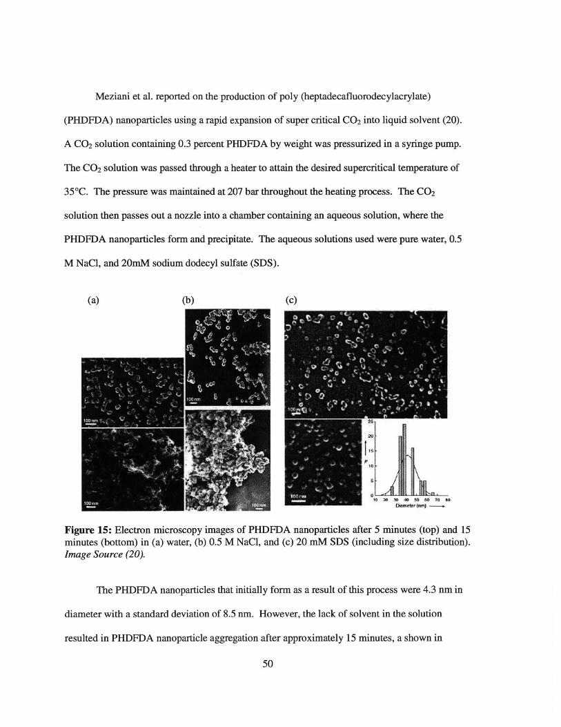
Meziani et al. reported on the production of poly (heptadecafluorodecylacrylate)
(PHDFDA) nanoparticles using a rapid expansion of super critical CO2 into liquid solvent (20).
A CO2 solution containing 0.3 percent PHDFDA by weight was pressurized in a syringe pump.
The CO2 solution was passed through a heater to attain the desired supercritical temperature of
35*C. The pressure was maintained at 207 bar throughout the heating process. The CO2
solution then passes out a nozzle into a chamber containing an aqueous solution, where the
PHDFDA nanoparticles form and precipitate. The aqueous solutions used were pure water, 0.5
M NaCl, and 20mM sodium dodecyl sulfate (SDS).
(a) (b) (c)
Figure 15: Electron microscopy images of PHDFDA nanoparticles after 5 minutes (top) and 15minutes (bottom) in (a) water, (b) 0.5 M NaCl, and (c) 20 mM SDS (including size distribution).Image Source (20).
The PHDFDA nanoparticles that initially form as a result of this process were 4.3 nm in
diameter with a standard deviation of 8.5 nm. However, the lack of solvent in the solution
resulted in PHDFDA nanoparticle aggregation after approximately 15 minutes, a shown in
50

Figure 15a. In order to prevent aggregation, a .5 molar (M) NaCi solution was used in hopes that
the increased ionic strength of the aqueous solution would slow down aggregation by stabilizing
the suspension. Nonetheless, the PHDFDA nanoparticles began to aggregate after in a manner
similar to the pure water, as can be seen in Figure 15b. As shown in figure 15cm, adding SDS, a
surfactant, to the aqueous solution prevented particle aggregation on the time scale of day;
however, this defeats the ideal purpose of the rapid expansion techniques.
3.2.7 Emulsion polymerization
Mufloz-Bonilla et al. reported on the production of polystyrene (PS) nanoparticles using
the conventional emulsion polymerization method (21). A solution of block copolymers of
polystyrene-b-poly-[poly(ethylene glycol) methyl ether methacrylate] (PS-b-P(PEGMA300) and
PS-b-P(PEGMA1 100)) in water was used as the surfactant. To this surfactant solution, additional
water and the styrene monomer was added under stirring. Finally, the initiator, either
ammonium persulfate, sodium thiosulfate, or potassium persulfate, was injected into the solution
to being polymerization. PS nanoparticles produced by this method were in the range of 217 to
494 nm in diameter.
Holzapfel et al. reported on the production of PS nanoparticles using the mini-
emulsion polymerization method (25). First, a mixture of styrene, acrylic acid, 2,20-azobis(2-
methylbutyronitrile) (V59) (the initiator), hydrophobic hexadecane, and n-(2,6-
diisopropylphenyl)-perylene-3,4-dicarboximide was produced. Separately, a solution of sodium
dodecylsulfate, the surfactant, in water was made. These two mixtures were combined under
stirring for an hour at 0*C to prevent premature polymerization. The temperature was then raised
51

to 724C and stirred at 500rpm for 20 hours as polymerization occurred. PS nanoparticles
produced by this method were in the range of 97 to 217 nm in diameter with polydispersity
indexes ranging from 0.003 to 0.402 depending on the concentration of materials used.
Jiang et al. reported on the production of PS nanoparticles using the mini-emulsion
polymerization method (27 First, a mixture of styrene, V59, and hexadecane was produced.
Separately, a solution of cetyltrimethylammonium chloride, the surfactant, in water was made.
These two mixtures were combined under stirring for an hour at 00 C to prevent premature
polymerization. The temperature was then raised to 72 0 C and stirred overnight as polymerization
occurred. PS nanoparticles produced by this method were 100 nm ±5 nm in diameter with a
polydispersity index of 0.01.
Pang et al. reported on the production of PS nanoparticles using the surfactant-free
emulsion polymerization method (30). A solution of the styrene monomer in water was created.
Finally, the initiator, azo-bis(isobutylamidine hydrochloride), was injected into the solution to
being polymerization. PS nanoparticles produced by this method were 248 nm ±12.3 nm in
diameter.
3.2.8 Lost Wax
Jiang et al. reported on the production of hollow polypyrrole (PPy) and solid
poly(p-phenylene vinylene) (PPV) nanoparticles using the lost-wax method. The PPy and PPV
nanoparticles both were created through a PS mold (32). A Si0 2 crystal template was made using
the methods previously described (31) and a macroporous PS mold was created off of this
52

template. The size and size distribution of the SiO 2 crystal template was 336nm (3.7 percent)
while the PS mold had voids with a 333nm (4.3 percent) diameter. PPy nanoparitces were
created from the mold by succesuvly exposing the PS mold to a 20 percent by volume pyrrole
ethanol solution and 0.05 M ferric chloride (FeCl 3). What remained behind were PPy
nanoparticles with a diameter of 322.0 (4.8%), as can be seen in Figurel6. PPV nanoparticles
were created by filling the PS mold with PPV precursor-methanol solution. The methanol
solution was slowly evaporated, allowing the PPV precursors to deposit slowly. The PS mold
was removed by dissolving it in toluene. The remaining PPV nanoparticles had a diameter of
310.5 (5.6 percent).
Figure 16: Electron microscopy images of a PPy crystal created from a PS mold. The PPycrystal (a) was exposed to excess pressure and the nanoparticles collapsed (b), demonstrating thatthey were hollow. Image Source (32).
The discrepancy in size distribution may be attributed to the fact that the PPy
nanoparticles were hollow capsules while the PPV nanoparticles where solid. It also can be
observed that the success of the lost-wax method relies on the ability to create monodisperse
SiC2 crystal templates as the majority of the size distribution in the PS mold and the polymeric
nanoparticles was inherited from the size distribution of the Si0 2. Size control of the polymeric
53
nanoparticles is direcity related to the ability to control the size of the SiC 2 nanoparticless
through the Staber process. The Stuber process is well understood and Si0 2 nanoparticles have
been created of sizes ranging from less than 50nm to greater than 2,000nm. The size of the
particles created can be controlled by changing the source and volume ratio of Si and the alcohol
used. The major drawback to this procedure is the length of time needed to produce the Si0 2
molds. Each layer of the mold takes up to a day to deposit and made ready for another layer.
Additionally, the Si0 2 crystal and PS mold have a one-time use, making the process even more
time intensive.
3.2.9 2D flow focusing
Karnik et al. reported the production of PLGA-PEG nanoparticles using a 2D
hydrodynamic forced flow method (10). The microfluidic device used for this method was
fashioned with PDMS using a standard micromolding process. The main channel where the flow
focusing occurs was made to be 20 pm wide, 60 pm tall, and one cm long. An organic solution
of the PLGA-PEG polymers dissolved in acetonitrile was made to flow down the main channel,
while two streams of pure water were used as sheaths. The organic solution contained either 50
mg/mL or 20 mg/mL of PLGA-PEW polymers. The flow ratio of the flow rate of the organic
stream to the total flow rate was maintained at 0.03-0.1.
54
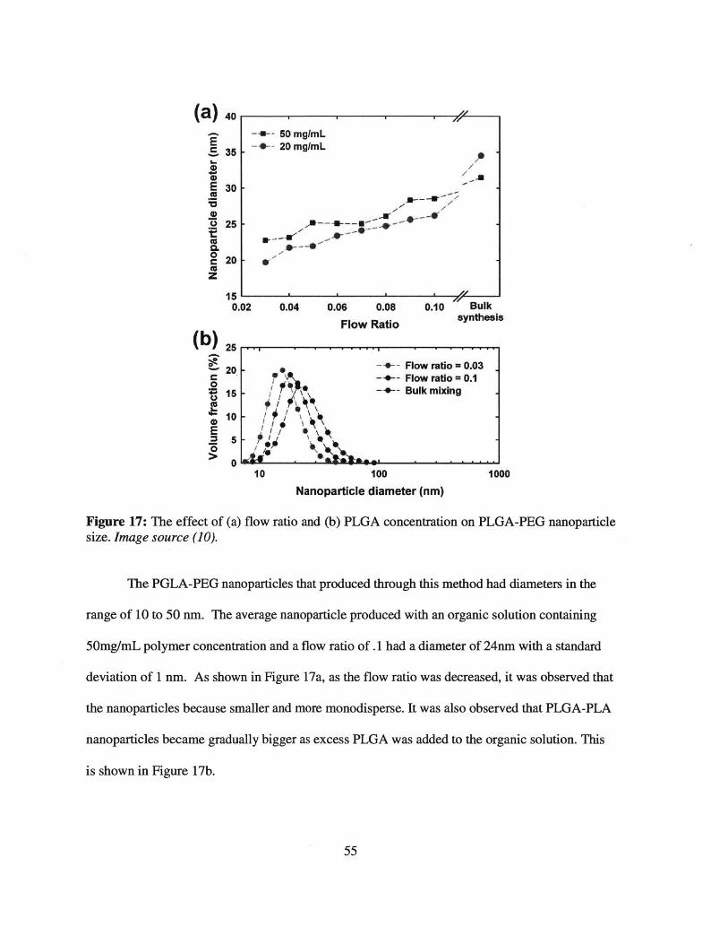
(a) 40
S, 3500E 30
5
0
c 20ccZ
0.04 0.06 0.08
Flow Ratio0.10 Bulk
synthesis
(b)
0
E
Figure 17: The effect ofsize. Image source (10).
25
20.
15
10
5
S
/ 7'I.* 1 IVyI ~
/ * I. ~\
!~<I \\~.
Au: ~ -
-+-- Flow ratio = 0.03--- Flow ratio= 0.1-".-- Bulk mixing
0 ' a - e - - - -10 100 1000
Nanoparticle diameter (nm)
(a) flow ratio and (b) PLGA concentration on PLGA-PEG nanoparticle
The PGLA-PEG nanoparticles that produced through this method had diameters in the
range of 10 to 50 nm. The average nanoparticle produced with an organic solution containing
50mg/mL polymer concentration and a flow ratio of .1 had a diameter of 24nm with a standard
deviation of 1 nm. As shown in Figure 17a, as the flow ratio was decreased, it was observed that
the nanoparticles because smaller and more monodisperse. It was also observed that PLGA-PLA
nanoparticles became gradually bigger as excess PLGA was added to the organic solution. This
is shown in Figure 17b.
55
-5--- S0mg/mL--- 20 mg/mL
1/-
--41r
W--0W-
or1-
I5,0.02
. -
-

Valencia et al. reported on the production of PLGA-lecithin-PEG and lipid-QD
nanoparticles using a 2D hydrodynamic forced flow method with inertial mixing (11). The
microfluidic device used for this method was fashioned with PDMS using a standard
micromolding process and uses a Telsa mixer to achieve inertial mixing. For the production of
PLGA-lecithin-PEG nanoparticles, an organic solution of the PLGA polymers dissolved in
acetonitrile at 1 mg/mL was made to flow down the main channel, while two streams of an
aqueous lecithin and DPSE-PEG were used as sheaths. The flow ratio of the flow rate of the
organic stream to the total flow rate was maintained at 0.1. For the production of DSPE-PEG
nanoparticles used to contain quantum dots, an organic solution of quantum dots dissolved in
THF at 0.5 mg/mL was made to flow down the main channel, while two streams of an aqueous
lecithin and DPSE-PEG were used as sheaths. The flow ratio of the flow rate of the organic
stream to the total flow rate was maintained at 0.1.
56

50 100 150 200
Nonoparticle Diameter (nm)
SE
100 no
Figure 18: Electron microscopy images and thelecithin-PEG and (b) DPSE-PEG nanoparticlessource (11).
19
34
00 so Iva 2W~
Nanoportice Size (nm)
corresponding size distribution of (a) PLGA-created using hydrodynamic flow focusing.
As can be seen in figure 18, the average PLGA-lecithin-PEG nanoparticle had a diamter
of 40 nm while the DPSE-PEG nanoparrticles used for quantum dots had an average diamter of
60 nm. The size of the nanoparticles was observed to be dependent on both the concentration of
the PLGA in the organic soltuion, and the molecular weight of the PLGA used. Increasing the
concentration of PLGA in the organic solution or using PLGa with a higher molecular weight
resulted in larger nanoparticles being produced.
57
(a)
0,
E-5
25
20
15
10
s
0
0
100 nm
(b)
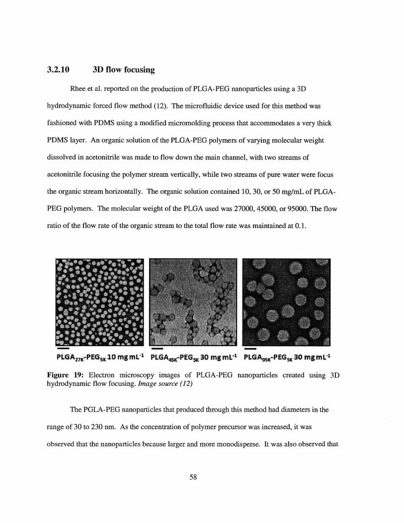
3.2.10 3D flow focusing
Rhee et al. reported on the production of PLGA-PEG nanoparticles using a 3D
hydrodynamic forced flow method (12). The microfluidic device used for this method was
fashioned with PDMS using a modified micromolding process that accommodates a very thick
PDMS layer. An organic solution of the PLGA-PEG polymers of varying molecular weight
dissolved in acetonitrile was made to flow down the main channel, with two streams of
acetonitrile focusing the polymer stream vertically, while two streams of pure water were focus
the organic stream horizontally. The organic solution contained 10, 30, or 50 mg/mL of PLGA-
PEG polymers. The molecular weight of the PLGA used was 27000, 45000, or 95000. The flow
ratio of the flow rate of the organic stream to the total flow rate was maintained at 0.1.
PLGAV-PEGK1O mgmL PLGA4-PEG 30 mg mL 1 PLGAM-PEGX30 mgmL1
Figure 19: Electron microscopy images of PLGA-PEG nanoparticles created using 3Dhydrodynamic flow focusing. Image source (12)
The PGLA-PEG nanoparticles that produced through this method had diameters in the
range of 30 to 230 nm. As the concentration of polymer precursor was increased, it was
observed that the nanoparticles because larger and more monodisperse. It was also observed that
58

PLGA-PLA nanoparticles became gradually bigger as PLGA of higher molecular weight was
used, as can be seen in Figure 19.
59
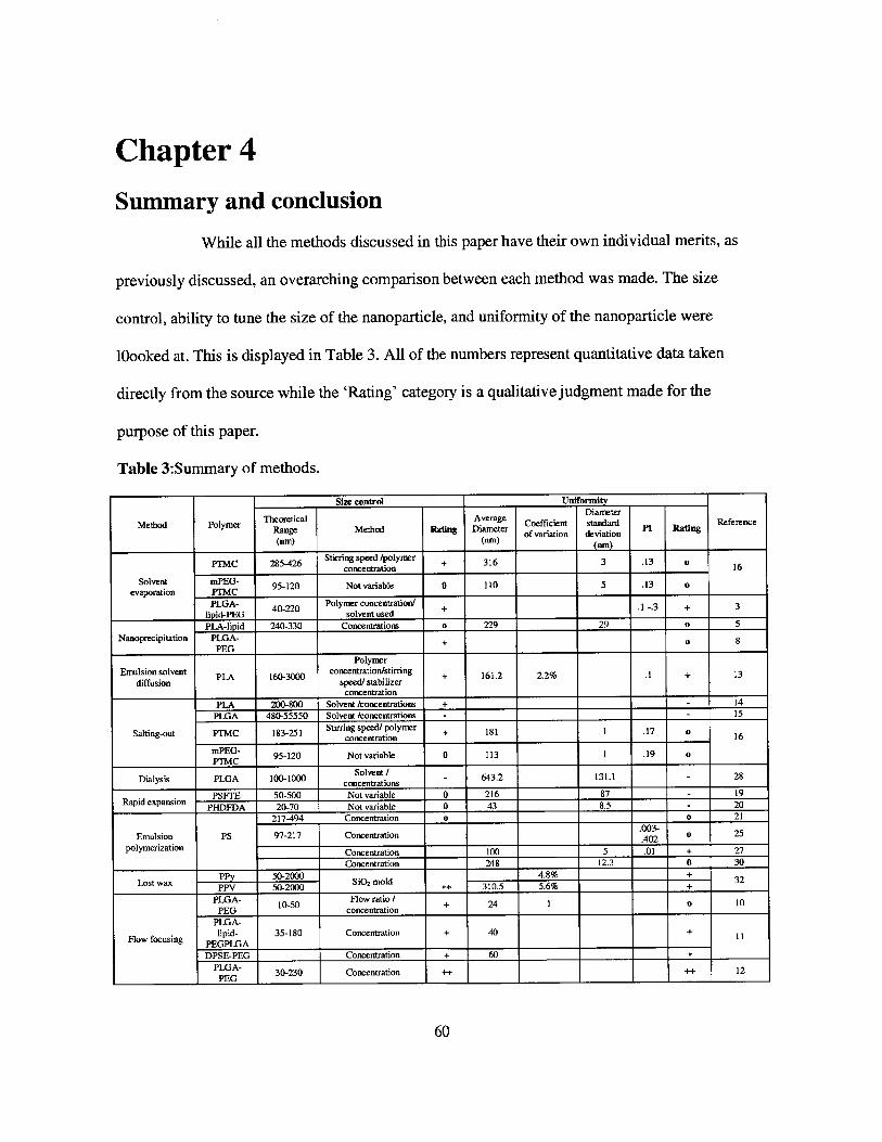
Chapter 4
Summary and conclusion
While all the methods discussed in this paper have their own individual merits, as
previously discussed, an overarching comparison between each method was made. The size
control, ability to tune the size of the nanoparticle, and uniformity of the nanoparticle were
10ooked at. This is displayed in Table 3. All of the numbers represent quantitative data taken
directly from the source while the 'Rating' category is a qualitative judgment made for the
purpose of this paper.
Table 3:Summary of methods.
Size control Un frmtyDiameter
Method Polymer TRlCal Method Ra Avng D er Coefficient standard Pi Radng Reference
(nm) (nm) of variation deviation(om) nm) _____ ________
PTMC 285-426 Stirring speed /polymer + 316 3 .13 oconcentration 16
Solvent mPEG- 95-120 Not variable 0 110 5 .13 oevaporation PTMC
PLGA- 40-220 Polymer concentration/ + .1-3 + 3lipid-PEG solvent usedPLA-lipid 240-330 Concentrations o 229 29 o 5
Nanoprecipitation PLGA- + 8PEG
PolymerEmulsion solvent PLA 160-3000 concentration/stirring + 161.2 2.2% .1 + 13
diffusion speed/ stabilizerconcentration
PLA 200-800 Solvent /concentrations + - 14PLGA 480-55550 Solvent /concentrations - - 15
Salting-out PTMC 183-251 Stirring speed/ polymer + 181 1 .17 0mE-concentration
____ 16
PEG 95-120 Not variable 0 113 1 .19 o
Dialysis PLGA 100-1000 concentr ions - 643.2 131.1 - 28
. PSFTE 50-500 Not variable 0 216 87 - 19Rapid expansion PHDFDA 20-70 Not variable 0 43 8.5 - 20
217-494 Concentration o o 21.003-
Emulsion PS 97-217 Concentration .023 o 25
polymerization Concentration 100 5 .01 + 27Concentration 248 12.3 0 30
Lost wax 50-2000 mold 4.8% + 32PPV 50-2000 ++_______ i~ 310.5 5.6% +
PLGA- 10-50 Flow ratio + 24 1 0 10PEG concentration
PLGA-
Flow focusing lipid- 35-180 Concentration + 40 + 11PEGPLGADPSE-PEG Concentration + 60 +
PLGA- 30-230 Concentration ++ ++ 12_______ PEG ______ I_______ I__ ___ ________ ________
60

Overall, all the methods except for lost-wax and 3D flow focusing have similar
results. This Is because all of the methods occur over a relatively long time scale. Mixing of the
ingredients occurs over a period of minutes to hours, giving similar results to each method.
Although the lost-wax method distinguishes itself from these other methods in terms of size
control and uniformity, it is highly dependent on the SiO 2 crystal structure, which takes a period
of days to produce. 3D flow focusing is by far the best method, when looking at just size control
and uniformity. This is due to the extremely quick time in which mixing occurs. 3D surpasses 2D
flow focusing because it deals with the problem of aggregation of polymers that occurs in PDMs
devices.
61
References(1) C. B. Murray, D. J. Norris, and M. G. Bawendi. Synthesis and characterization of nearly
monodisperse CdE (E = sulfur, selenium, tellurium) semiconductor nanocrystallites.Journal of the American Chemical Society. 115(19): 8706-8715 (1993)
(2) W. Stdber, A. Fink, and E. Bohn. Controlled Growth of Monodisperse Silica Spheres inthe Micron Size Range. Journal of Colloid and Interface Science. 26(1): 62-69 (1968).
(3) J. M. Chan, L. Zhang, K. P. Yuet, G. Liao, J. Rhee, R. Langer, 0. C. Farokhzad, PLGA-lecithin-PEG core-shell nanoparticles for controlled drug delivery. Biomaterials. 30(8):1627-1634 (2009)
(4) R. Cortesia, E. Espositoa, G. Lucab, C. Nastruzzi. Production of lipospheres as carriersfor bioactive compounds. Biomaterials. 23(11): 2283-2294 (2002)
(5) H. Fessi, F. Puisieux, J. P. Devissaguet, N. Ammoury, and S.Benita. Nanocapsuleformation by interfacial polymer deposition following solvent displacement. Int. J.Pharm. 55:R1-R4 (1989)
(6) S. Galindo-Rodriguez, E. Alldmann, H. Fessi, and E. Doelker. PhysicochemicalParameters Associated with Nanoparticle Formation in the Salting-out, Emulsification-Diffusion, and Nanoprecipitation Methods. Pharmaceutical Research. 21(8): 1428-1439(2004)
(7) U. Bilati, E. Allemann, and E. Doelker. Development of a nanoprecipitation methodintended for the entrapment of hydrophilic drugs into nanoparticles. European Journal ofPharmaceutical Sciences. 24(1): 67-75 (2005)
(8) J. Cheng, B. A. Teply, I. Sherifi, J.e Sung, G. Luther, F. X. Gu, E. Levy-Nissenbaum, A.F. Radovic-Moreno, R.Langer, 0. C. Farokhzad. Formulation of functionalized PLGA-PEG nanoparticles for in vivo targeted drug delivery. Biomaterials 28(5): 869-876 (2007)
(9) L. Zhang, J. M. Chan, F. X. Gu, J. Rhee, A. Z. Wang, A. F. Radovic-Moreno, F. Alexis,R. Langer, and 0. C. Farokhzad. Self-Assembled Lipid-Polymer Hybrid Nanoparticles:A Robust Drug Delivery Platform. ACS Nano. 2(8): 1696-1702 (2008)
(10) R. Karnik, F. Gu, P. Basto, C. Cannizzaro, L. Dean, W. Kyei-Manu, R. Langer, and 0.C. Farokhzad. Microfluidic Platform for Controlled Synthesis of PolymericNanoparticles. Nano Letters. 8 (9): 2906-2912 (2008)
(11) P. M. Valencia, P. A. Basto, L. Zhang, M. Rhee, R. Langer, 0. C. Farokhzad, and R.Karnik. Single-Step Assembly of Homogenous Lipid-Polymeric and Lipid-QuantumDot Nanoparticles Enabled by Microfluidic Rapid Mixing. ACS Nano. 4 (3): 1671-1679(2010)
(12) M. Rhee, P. M. Valencia, M. I. Rodriguez, R. Langer, 0. C. Farokhzad, R. Karnik.Synthesis of Size-Tunable Polymeric Nanoparticles Enabled by 3D Hydrodynamic FlowFocusing in Single-Layer Microchannels. Advanced Materials. 23(12): 79-83 (2011)
(13) D. Quintanar-Guerrero, H. Fessi, E. Allkmann, E. Doelker. Influence of stabilizingagents and preparative variables on the formation of poly(d,l-lactic acid) nanoparticles byan emulsification-diffusion technique. International Journal of Pharmaceutics. 142(2):133-141 (1996)
(14) E. Alldmann, J. Leroux, R. Gurny, and E. Doelker. In Vitro Extended-Release Propertiesof Drug-Loaded Poly(DL-Lactic Acid) Nanoparticles Produced by a Salting-OutProcedure. Pharmaceutical Research. 10(12): 1732-1737(1993)
62

(15) P. Perugini, S. Simeoni, S. Scalia, I. Genta, T. Modena, B. Conti, F. Pavanetto. Effect ofnanoparticle encapsulation on the photostability of the sunscreen agent, 2-ethylhexyl-p-methoxycinnamate. International Journal of Pharmaceutics. 246(1-2) 37-45(2002)
(16) Z. Zhang, D. W. Grijpma, and J. Feijen. Poly(trimethylene carbonate) andmonomethoxy poly(ethylene glycol)-block-poly(trimethylene carbonate) nanoparticlesfor the controlled release of dexamethasone. Journal of Controlled Release. 111(3):Pages 263-270 (2006)
(17) X. Song, Y. Zhao, W. Wu, Y. Bi, Z. Cai, Q.g Chen, Y. Li, and S. Hou. PLGAnanoparticles simultaneously loaded with vincristine sulfate and verapamilhydrochloride: Systematic study of particle size and drug entrapment efficiency.International Journal of Pharmaceutics. 350(1-2): 320-329 (2008)
(18) Y. Jeong, C.Cho, S. Kim, K. Ko, S. Kim, Y. Shim, and J. Nah. Preparation of Poly(DL-lactide-co-glycolide) Nanoparticles Without Surfactant. Journal of Applied PolymerScience. 80(12): 2228-2236 (2001)
(19) K. T. Lim, G. H Subban, H. S. Hwang, J. T. Kim, C.S. Ju, K. P. and Johnston. NovelSemiconducting Polymer Particles by Supercritical Fluid Process. Macromol. RapidCommun. 26(22): 1779-1783 (2005)
(20) M. J. Meziani, P. Pathak, R. Hurezeanu, M.C Thies, R. M. Enick, and Y.P. Sun.Supercritical-Fluid Processing Technique for Nanoscale Polymer Particles. AngewandteChemie International Edition. 43(6): 704-707 (2004)
(21) A. Mufioz-Bonilla, A. M. van Herk, and J. P. A. Heuts. Preparation of Hairy Particlesand Antifouling Films Using Brush-Type Amphiphilic Block Copolymer Surfactants inEmulsion Polymerization. Macromolecules. 43(6): 2721-2731 (2010)
(22) C. Solans, P. Izquierdo, J. Nolla, N. Azemar, M.J. Garcia-Celma. Nano-emulsions.Current Opinion in Colloid & Interface Science. 10(3-4): 102 - 110 (2005)
(23) M. Antonietti and K. Landfester. Polyreactions in miniemulsions. Prog Polym. Sci.27(4): 689-757 (2002)
(24) J. Schork, Y. Luo, W. Smulders, J. P. Russum, A. Butt6, and K. Fontenot. MiniemulsionPolymerization. Adv Polym Sci. 175:175: 129-255 (2005)
(25) V. Holzapfelm, A. Musyanovych, K. Landfester, M. R. Lorenz, and V. Mailander.Preparation of fluorescent carboxyl and amino functionalized polystyrene particles byminiemulsion polymerization as markers for cells. Macromolecular Chemistry andPhysics. 206(24): 2440-2449 (2005)
(26) A. Musyanovych, R. Rossmanith, C. Tontsch, amd K. Landfester. Effect of hydrophiliccomonomer and surfactant type on the colloidal stability and size distribution ofcarboxyl-and amino-functionalized polystyrene particles prepared by miniemulsionpolymerization. Langmuir. 23(10): 5367-5376 (2007)
(27) X. Jiang, J. Dausend, M. Hafner, A. Musyanovych, C. R6cker, K. Landfester, K., V.Mailander, and G. U. Nienhaus. Specific effects of surface amines on polystyrenenanoparticles in their interactions with mesenchymal stem cells. Biomacromolecules.11(3): 748-753 (2010)
(28) F. Candau, M. Pabon, and J. Y. Anquetil. Polymerizable microemulsions: some criteriato achieve an optimal formulation. Colloids and Surfaces A: Physicochemical andEngineering Aspects. 153(1): 47-59 (1999).
63
(29) Z. Song and G. W. Poehlein. Kinetics of emulsifier-free emulsion polymerization ofstyrene. Journal of Polymer Science Part A: Polymer Chemistry. 28(9): 2359-2392(1990)
(30) S. W. Pang, H. Y. Park, Y.S. Jang, W. S. Kim, and J. H. Kim. Effects of charge densityand particle size of poly (styrene/(dimethylamino) ethyl methacrylate) nanoparticle forgene delivery in 293 cells. Colloids and Surfaces B: Biointerfaces. 26(3): 213-222 (2002)
(31) P. Jiang, J. F. Bertone, K. S. Hwang, and V. L. Colvin. Single-Crystal ColloidalMultilayers of Controlled Thickness. Chemistry of Materials. 11(8): 2132-2140 (1999)
(32) P.Jiang, J.F. Bertone, V. L. Colvin. A Lost-Wax Approach to Monodisperse Colloidsand Their Crystals. Science. 291(5503): 453-457 (2001)
(33) X. Mao, J. R. Waldeisen, and T. J. Huang. 'Microfluidic drifting"-implementingthree-dimensional hydrodynamic focusing with a single-layer planar microfluidic device.Lab on a Chip. 7(10): 1260-1262 (2007)
64