AN ANALYSIS OF PHUGOID OSCILLATIONS OF UNMANNED FLYING...
8
Journal of KONES Powertrain and Transport, Vol. 23, No. 2 2016 AN ANALYSIS OF PHUGOID OSCILLATIONS OF UNMANNED FLYING WING Pamela Mioduska Institute of Aviation, Department of Aerodynamics and Flight Mechanics Krakowska Avenue 110/114, 02-256 Warsaw, Poland tel.: +48 22 8460011 ext. 359, fax: +48 22 8464432 e-mail: [email protected] Abstract The flying wing configuration has been considered by airplane designers for more than one hundred years. Tailless aircraft have been inspired by nature and its solutions. In present times, this configuration is used to design Unmanned Aerial Vehicle (UAV). This type of plane could serve personal, military and research purposes. The flying wing is characterized by large amount of payload space, smaller wetted area than conventional airplane and stealth capability. This makes, that it is widely applicable in rescue operations, geodetic and cartographic research, monitoring of natural resources, taking pictures or videos. Despite all the merits of tailless plane, it also has its downsides. The main problem of this type of aircraft is longitudinal stability. A conventional airplane can compensate the pitch moment of the wing with its horizontal tail but a flying wing is tailless. A slow decay of oscillations amplitude is the problem, which can be solved by active control or proper aerodynamic design. A combination of geometric characteristic such as sweep, taper, twist and location of vertical stabilizers along span, can lead to stable flying wing. In this article, the results of phugoid oscillations analysis of unmanned flying wing are presented. Research platform was X8-2, popular flying wing UAV, designed for First Person View (FPV) method to control the vehicle. The calculations were performed using 3D panel method. On the basis of calculations for three versions of the model aircraft, the dynamic characteristics were created. The analysis of longitudinal stability undertaken here has indicated propriety of applied changes in geometry. Keywords: UAV, flying wing, longitudinal stability, phugoid oscillations 1. Introduction A flying wing configuration has been considered by airplane designers for more than one hundred years. Tailless aircraft have been inspired by nature and its solutions. The shape of this type of airplane is adapted from the gliding seed of the Java palm tree (zanonia macrocarpa). This seed grows with two curved and very elastic wings. When the seed released from the tree, it glides with the wind. A flying wing is characterised by tailless structure with often no defined fuselage. As in any other airplane, a few wing configurations may be distinguished. The wings may be straight, swept back, or swept forward. Inside the main wing, structure is a place for payload, fuel, and equipment. However, this configuration may have various small protuberances such as pods, nacelles or vertical fins, stabilizers. In present time, this configuration is often used to design Unmanned Aerial Vehicle (UAV). A military aviation sets a priority on unmanned airplanes development that includes flying wing projects such as X-45 [7] or X-47B [6]. Unmanned flying wings could serve not only in military but also for personal or research purposes. UAVs are widely applicable in rescue operations, geodetic and cartographic research, monitoring of natural resources, taking pictures or videos. The advantage of tailless airplane is smaller wetted area than it is for conventional airplane. Moreover, the wing structure can be lighter because of load distribution. An equipment and payload located inside the wing structure reduces the load. This eliminates the need to build heavy ISSN: 1231-4005 e-ISSN: 2354-0133 DOI: 10.5604/12314005.1213599
-
Upload
nguyenxuyen -
Category
Documents
-
view
218 -
download
3
Transcript of AN ANALYSIS OF PHUGOID OSCILLATIONS OF UNMANNED FLYING...

Journal of KONES Powertrain and Transport, Vol. 23, No. 2 2016
AN ANALYSIS OF PHUGOID OSCILLATIONS OF UNMANNED FLYING WING
Pamela Mioduska
Institute of Aviation, Department of Aerodynamics and Flight Mechanics Krakowska Avenue 110/114, 02-256 Warsaw, Poland tel.: +48 22 8460011 ext. 359, fax: +48 22 8464432
e-mail: [email protected]
Abstract
The flying wing configuration has been considered by airplane designers for more than one hundred years. Tailless aircraft have been inspired by nature and its solutions. In present times, this configuration is used to design Unmanned Aerial Vehicle (UAV). This type of plane could serve personal, military and research purposes. The flying wing is characterized by large amount of payload space, smaller wetted area than conventional airplane and stealth capability. This makes, that it is widely applicable in rescue operations, geodetic and cartographic research, monitoring of natural resources, taking pictures or videos. Despite all the merits of tailless plane, it also has its downsides. The main problem of this type of aircraft is longitudinal stability. A conventional airplane can compensate the pitch moment of the wing with its horizontal tail but a flying wing is tailless. A slow decay of oscillations amplitude is the problem, which can be solved by active control or proper aerodynamic design. A combination of geometric characteristic such as sweep, taper, twist and location of vertical stabilizers along span, can lead to stable flying wing.
In this article, the results of phugoid oscillations analysis of unmanned flying wing are presented. Research platform was X8-2, popular flying wing UAV, designed for First Person View (FPV) method to control the vehicle. The calculations were performed using 3D panel method. On the basis of calculations for three versions of the model aircraft, the dynamic characteristics were created. The analysis of longitudinal stability undertaken here has indicated propriety of applied changes in geometry.
Keywords: UAV, flying wing, longitudinal stability, phugoid oscillations
1. Introduction
A flying wing configuration has been considered by airplane designers for more than onehundred years. Tailless aircraft have been inspired by nature and its solutions. The shape of this type of airplane is adapted from the gliding seed of the Java palm tree (zanonia macrocarpa). This seed grows with two curved and very elastic wings. When the seed released from the tree, it glides with the wind.
A flying wing is characterised by tailless structure with often no defined fuselage. As in any other airplane, a few wing configurations may be distinguished. The wings may be straight, swept back, or swept forward. Inside the main wing, structure is a place for payload, fuel, and equipment. However, this configuration may have various small protuberances such as pods, nacelles or vertical fins, stabilizers.
In present time, this configuration is often used to design Unmanned Aerial Vehicle (UAV). A military aviation sets a priority on unmanned airplanes development that includes flying wing projects such as X-45 [7] or X-47B [6]. Unmanned flying wings could serve not only in military but also for personal or research purposes. UAVs are widely applicable in rescue operations, geodetic and cartographic research, monitoring of natural resources, taking pictures or videos.
The advantage of tailless airplane is smaller wetted area than it is for conventional airplane. Moreover, the wing structure can be lighter because of load distribution. An equipment and payload located inside the wing structure reduces the load. This eliminates the need to build heavy
ISSN: 1231-4005 e-ISSN: 2354-0133 DOI: 10.5604/12314005.1213599

P. Mioduska
wing, which might transferring large loads. The flying wing is characterized by large amount of payload space and stealth capability.
Despite all the merits of tailless plane, it also has some weaknesses. The main problem of this type of aircraft is a longitudinal stability. A conventional airplane can compensate the moment of the wing with its horizontal tail but a flying wing is tailless. A slow decay of oscillations amplitude is the problem, which can only be solved by active control or proper aerodynamic design. A combination of geometric characteristic such as sweep, taper, twist and location of vertical stabilizers along span can lead to stable flying wing.
The subject of this study was the longitudinal dynamic stability of unmanned flying wing. Dynamic stability concerns the resulting motion over a span of time and the term longitudinal dynamic stability refers to stability around the lateral axis of the airplane – pitch stability.
The governing equations for the longitudinal motion are ordinary differential equations with constant coefficients. The longitudinal flight equations of motion can be written using the force equations along and perpendicular to the velocity. There is no roll or yaw motion. Body-fixed coordinate system and angle of attack, path angle, and pitch angle are shown in Fig. 1. Finally, the general equations of motion become:
⎩⎪⎨
⎪⎧𝑇𝑇 − 𝐷𝐷 −𝑚𝑚 ∙ 𝑔𝑔 ∙ sin(𝛾𝛾) = 𝑚𝑚 ∙ �̇�𝑉𝐿𝐿 − 𝑚𝑚 ∙ 𝑔𝑔 ∙ cos(𝛾𝛾) = 𝑚𝑚 ∙ 𝑉𝑉 ∙ �̇�𝛾
𝑄𝑄 = 𝐼𝐼𝑦𝑦 ∙ �̇�𝑞 𝑞𝑞 = �̇�𝜃 ,
(1)
where: 𝑇𝑇 – thrust, 𝐷𝐷 – drag, 𝑚𝑚 – mass, 𝑔𝑔 = 9.81 [𝑚𝑚
𝑠𝑠2] ,
𝛾𝛾 – flight path angle (angle between velocity and local horizontal), 𝑉𝑉 – airspeed, 𝐿𝐿 – lift, 𝑄𝑄 – pitching moment, 𝐼𝐼𝑦𝑦 – moment of inertia about pitch axis, 𝑞𝑞 – pitch rate, 𝜃𝜃 – pitch angle.
Fig. 1. Body-fixed coordinate system and angle of attack, path angle, and pitch angle
Assuming that control surfaces deflections are equal to zero, longitudinal equations (1) can be
rewritten as:
248
, ,
,
An Analysis of Phugoid Oscillations of Unmanned Flying Wing
�̇�𝑥 = 𝐴𝐴 ∙ 𝑥𝑥, (2)
where: 𝑥𝑥 = [𝑉𝑉, 𝛾𝛾, 𝑞𝑞,𝜃𝜃 ]𝑇𝑇 – state vector, 𝐴𝐴 – stability derivatives matrices.
A solution of longitudinal equations (2) might be expressed by:
𝑥𝑥(𝑡𝑡) = 𝑋𝑋0 ∙ 𝑒𝑒𝜆𝜆∙𝑡𝑡 , (3) where: 𝑋𝑋0 – eigenvector, 𝜆𝜆 – eigenvalues.
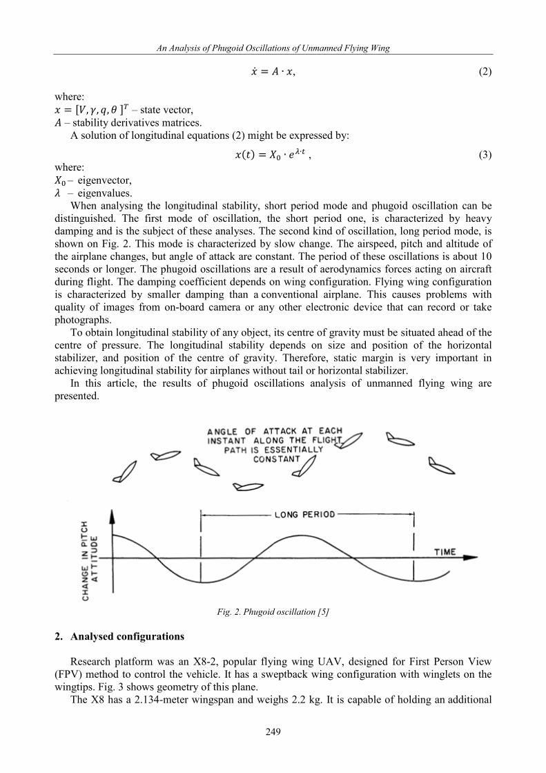
When analysing the longitudinal stability, short period mode and phugoid oscillation can be distinguished. The first mode of oscillation, the short period one, is characterized by heavy damping and is the subject of these analyses. The second kind of oscillation, long period mode, is shown on Fig. 2. This mode is characterized by slow change. The airspeed, pitch and altitude of the airplane changes, but angle of attack are constant. The period of these oscillations is about 10 seconds or longer. The phugoid oscillations are a result of aerodynamics forces acting on aircraft during flight. The damping coefficient depends on wing configuration. Flying wing configuration is characterized by smaller damping than a conventional airplane. This causes problems with quality of images from on-board camera or any other electronic device that can record or take photographs.
To obtain longitudinal stability of any object, its centre of gravity must be situated ahead of the centre of pressure. The longitudinal stability depends on size and position of the horizontal stabilizer, and position of the centre of gravity. Therefore, static margin is very important in achieving longitudinal stability for airplanes without tail or horizontal stabilizer.
In this article, the results of phugoid oscillations analysis of unmanned flying wing are presented.
Fig. 2. Phugoid oscillation [5]
2. Analysed configurations
Research platform was an X8-2, popular flying wing UAV, designed for First Person View
(FPV) method to control the vehicle. It has a sweptback wing configuration with winglets on the wingtips. Fig. 3 shows geometry of this plane.
The X8 has a 2.134-meter wingspan and weighs 2.2 kg. It is capable of holding an additional
249

P. Mioduska
2.3 kg of payload. Its electric motor drives a pusher propeller. The aircraft attains a cruise speed of 65 km/h. Tab. 1 provides information on specification of X8-2 [1].
Fig. 3. View X8-2 flying wing [1]
Tab. 1. UAV specification [1]
Empty weight Mempty 2.2 kg Maximum take-off weight Mtow 4.5 kg Wingspan b 2134 mm Wing area S 50 dm2 Tip chord ctip 185 mm Root chord croot 458 mm Mean aerodynamic chord M.A.C. 342 mm Endurance E 2 hr Typical cruising speed Vc 65 km/h Stall speed Vs 10.5 km/h Maximum speed Vd 110 km/h
The wing of the X8 UAV features the airfoils from Selig S5010 family, with small-reflexed
camber line. For a tailless airplane with swept wing, these airfoils are recommended because of low moment coefficient. The geometry of Selig S5010 airfoil family is presented in Fig. 4 and 5.
Fig. 4. Airfoil cross-section S5010
Fig. 5. Airfoil cross-section modification of S5010
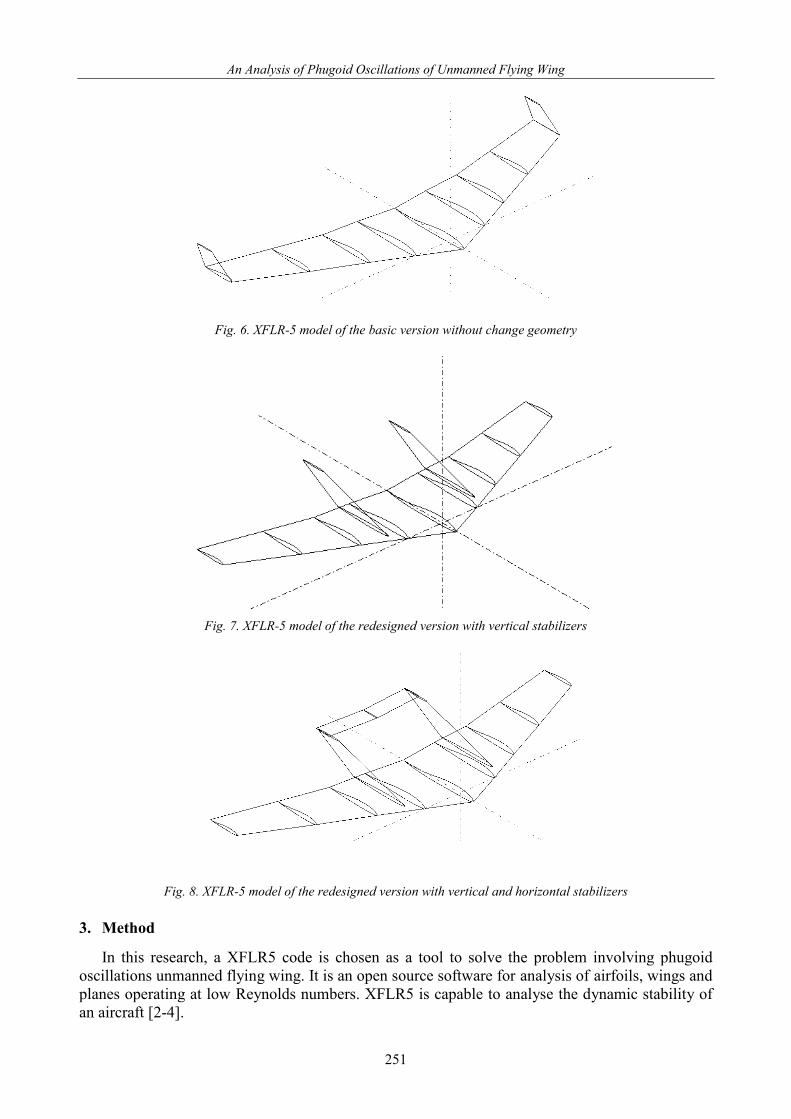
The simulations were conducted for three configurations: the basic version without change of
lifting surfaces geometry, redesigned with vertical stabilizers and redesigned with vertical and horizontal stabilizers. The geometry of XFLR5 models are set out in Fig. 6, 7 and 8. These models are simplified and the influence of fuselage on characteristics is neglected.
250
An Analysis of Phugoid Oscillations of Unmanned Flying Wing
Fig. 6. XFLR-5 model of the basic version without change geometry
Fig. 7. XFLR-5 model of the redesigned version with vertical stabilizers
Fig. 8. XFLR-5 model of the redesigned version with vertical and horizontal stabilizers
3. Method In this research, a XFLR5 code is chosen as a tool to solve the problem involving phugoid
oscillations unmanned flying wing. It is an open source software for analysis of airfoils, wings and planes operating at low Reynolds numbers. XFLR5 is capable to analyse the dynamic stability of an aircraft [2-4].
251
P. Mioduska
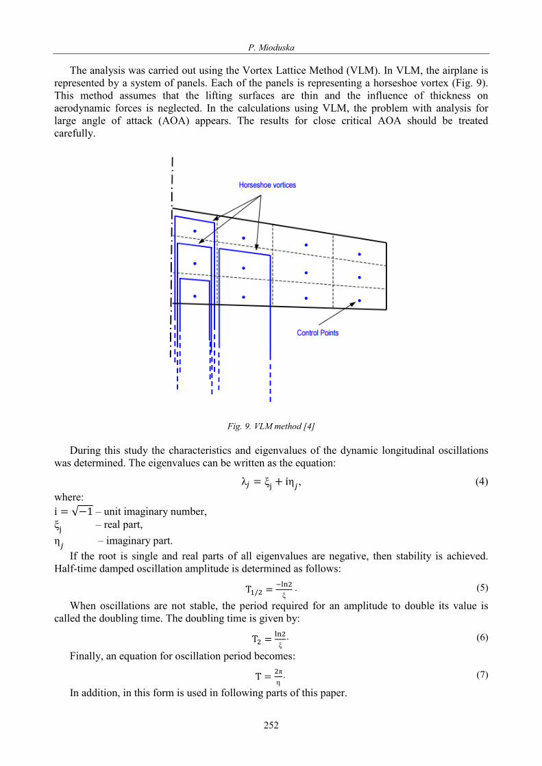
The analysis was carried out using the Vortex Lattice Method (VLM). In VLM, the airplane is represented by a system of panels. Each of the panels is representing a horseshoe vortex (Fig. 9). This method assumes that the lifting surfaces are thin and the influence of thickness on aerodynamic forces is neglected. In the calculations using VLM, the problem with analysis for large angle of attack (AOA) appears. The results for close critical AOA should be treated carefully.
Fig. 9. VLM method [4]
During this study the characteristics and eigenvalues of the dynamic longitudinal oscillations
was determined. The eigenvalues can be written as the equation:
λ𝑗𝑗 = ξj + iη𝑗𝑗 , (4) where: i = √−1 – unit imaginary number, ξj – real part, η𝑗𝑗 – imaginary part.
If the root is single and real parts of all eigenvalues are negative, then stability is achieved. Half-time damped oscillation amplitude is determined as follows:
T1/2 = −ln2ξ
. (5)
When oscillations are not stable, the period required for an amplitude to double its value is called the doubling time. The doubling time is given by:
T2 = ln2ξ
. (6)
Finally, an equation for oscillation period becomes:
T = 2πη . (7)
In addition, in this form is used in following parts of this paper.
252

An Analysis of Phugoid Oscillations of Unmanned Flying Wing
4. Results
During this study the characteristics and eigenvalues of the dynamic longitudinal oscillations was determined. Based on (4), (5), (6) and (7) was calculated oscillation period, half-time or doubling time. Tab. 2 summarized these results.
Tab. 2 Eigenvalues, period, half-time or doubling time for three version of aircraft
Configuration Eigenvalues Oscillation
period Half-time/ Doubling
time
BASIC VERSION 𝜆𝜆 = 0.0022 ± 0.8255𝑖𝑖 𝑇𝑇 = 7.61𝑠𝑠 𝑇𝑇2 = 315𝑠𝑠 WITH VERTICAL
STABILISERS 𝜆𝜆 = −0.013 ± 0.7259𝑖𝑖 𝑇𝑇 = 8.65𝑠𝑠 𝑇𝑇1/2 = 533𝑠𝑠
WITH VERTICAL AND HORIZONTAL
STABILISERS 𝜆𝜆 = −0.016 ± 0.5827𝑖𝑖 𝑇𝑇 = 10.75𝑠𝑠 𝑇𝑇1/2 = 433𝑠𝑠
The results show, that:
− the basic version without change geometry is not stable, the amplitude is arising, − the redesigned version with vertical stabilizers is stable, the first period oscillation is longer
than for basics version, − the redesigned version with vertical and horizontal stabilizers is also stable; the period is longer
than for basics version and version with vertical stabilizers only, the half time is about 100 seconds less than version with vertical stabilizers.
5. Conclusions and future work Throughout this paper, the procedures and result of the simulation studies have been presented.
The results show, that the basic version without changes is not stable. The phugoid oscillations are not damped and the amplitude is arising. This causes problems with control the airplane and quality of images from cameras.
It can be concluded that the application of vertical stabilizers makes the airplane stable. The period of oscillation for redesigned version, with vertical stabilizers, is longer than for basic version, but the damping is too small and the half time is about 10 minutes.
The redesigned version with vertical and horizontal stabilizers is also stable. The oscillation period is longer than for the basics version and the version with vertical stabilizer. The half time is less than this for the version with vertical stabilizers.
The analysis of longitudinal stability, undertaken here, has indicated propriety of applied changes in geometry. Main limitations of the result are simplification of VLM and definition of geometry. Future work will involve enhanced model of geometry in manner that reflects the influence of fuselage on characteristics.
The next stage of research will be an optimization of geometry and location of vertical and horizontal stabilizer to achieve the half time about a few minutes. It is recommended that further research should be undertaken experimentally, confirming the numerical results.
References [1] Aeroelectronics X8 Flying Wing Datasheet, http://www.airelectronics.es/. [2] http://www.xflr5.com. [3] Deperrois, A., About stability analysis using XFLR5, November 2010.
253

P. Mioduska
[4] Deperrois, A., Guidelines for XFLR5, XFLR5 Analysis of foils and wings operating at low Reynolds numbers.
[5] Hurt, H. H., Jr., Aerodynamics for Naval Aviators, Skyhorse Publishing Inc, p. 286, New York 2012.
[6] Whittenbury, J., Configuration design development of the Navy UCAS-D X-47B, Report No.: AIAA-2011-7041, 2011.
[7] Wise, K., X-45 Program overview and flight test status, Report No.: AIAA-2003-6645, 2003.
254