AN ANALYSIS OF NON-AXISYMMETRIC BACKWARD EXTRUSION
5
M. Plančak et al. Analiza tehnologije protusmjernog deformiranja ne-aksijalno simetričnih dijelova Tehnički vjesnik 19, 4(2012), 953-957 953 ISSN 1330-3651 UDC/UDK 621.777.011:620.17 AN ANALYSIS OF NON-AXISYMMETRIC BACKWARD EXTRUSION Miroslav Plančak, Dejan Movrin, Dragiša Vilotić, Zlatan Car, Aljoša Ivanišević, Igor Kačmarčik Preliminary notes Manufacturing of complex parts by cold extrusion often offers technical and economical advantages when compared with the conventional production methods. In the initial stage of industrial application of cold extrusion mainly axisymmetric components were produced. In the course of further development, application of cold extrusion has been extended to more complex and non-axisymmetric shapes. These have increased the significance and broaden the application fields of cold extrusion within other production technologies, especially in the automobile industry. Current paper elaborates non axisymmetric cold extrusion. Focus of the work is placed on the backward extrusion by the punch with square cross section. In this process load – stroke has been determined as well as punch pressure, and strain and stress distribution in two characteristic different workpiece cross sections. The process has been analyzed by FE method and experimentally. For the experimental investigation special tooling has been designed and made. Keywords: cold extrusion, experiment, FE, non-axisymmetric shape Analiza tehnologije protusmjernog deformiranja ne-aksijalno simetričnih dijelova Preliminary notes U usporedbi s konvencionalnim metodama obrade, proizvodnja složenih dijelova hladnim istiskivanjem često nudi tehničke i ekonomske prednosti. U ranoj fazi industrijske primjene hladnim istiskivanjem su se uglavnom izgrađivali aksijalno simetrični dijelovi. U toku daljnjeg razvoja, tehnologija hladnog istiskivanja primijenjuje se i za izradu složenijih ne-aksijalno simetričnih oblika. Samim time povećan je značaj i proširena područja primjene protusmjernog deformiranja i u drugim oblastima industrije, posebice u automobilskoj industriji. U radu su prikazana istraživanja tehnologije protusmjernog deformiranja ne-aksijalno simetričnih dijelova, s akcentom na izradu dijelova pomoću žigova kvadratnog poprečnog presjeka. Ispitivane su vrijednosti deformacione sile i pritisaka na čelo žiga, kao i naponsko-deformacijsko stanje u dva karakteristična presjeka radnog komada. Proces je analiziran metodom konačnih elemenata (MKE) i eksperimentalno. Za eksperimentalna istraživanja konstruirani su i izrađeni specijalni alati. Ključne riječi: hladno istiskivanje, eksperiment, MKE, ne-aksijalno simetrični dijelovi 1 Introduction Cold extrusion is one of the most efficient processes in the technology of plasticity. This method has the feature of minimal material consumption and improved mechanical properties of the extruded component [1], [2]. Further advantages of this process are improved surface finish, minimum requirement of finishing operations and high production rates. On the other hand, the main drawback of the process is high pressures which occur on punch and die. Therefore design, material selection and heat treatment of tooling elements are very important for successful performance of the cold extrusion. In this process, which is carried out at room temperature, punch applies pressure to the round billet which then flows in the required direction between die and punch. According to the geometrical relation between the tool elements and billet material, there exist four basic types of cold extrusion: forward, backward, hydrostatic and impact extrusion [3]. In the relevant literature different classification of basic extrusion processes can be also found [2]. One of the significant trends in the research and application of cold extrusion is the increase of the workpiece complexity. This can be achieved by combining of the mentioned basic extrusion processes which, in most cases, leads to complex material flow within the die. As a result, wider spectrum of component geometries can be obtained. Theoretical analyses of basic types of cold extrusion are well established, whereas for so called "non-conventional" types of extrusion a certain dearth of knowledge can be noted. In [4] authors elaborate combined forward/backward extrusion of non-axisymmetric parts using UBET approach. They concluded that the proposed method is suitable for deriving the main process parameters. Radial/backward extrusion is presented in [5]. In this process workpiece material flows both in axial and radial direction fulfilling the opening in the die. It has been concluded that geometry of the die has a substantial influence on material flow and thus on component geometry, whilst friction has little. Some authors suggested an empirical approach in investigation of non-axisymmetric extrusion. In [6] equations for load calculation of such a process are proposed and compared with experimental results. Experimental investigation of cold extrusion by punch with various non-axisymmetric cross sections is presented in [7]. Author concluded that there was a little impact of punch geometry on the maximum load, for the same logarithmic deformation. Figure 1 Gedora – screw wrenches [8] One of the typical applications of non – axisymmetric cold extrusion is a mass production of Gedora – screw wrenches. In Fig. 1 elements with square, triangle and hexagonal cross section, produced by this technology, are shown.
Transcript of AN ANALYSIS OF NON-AXISYMMETRIC BACKWARD EXTRUSION
M. Plančak et al. Analiza tehnologije protusmjernog deformiranja ne-aksijalno simetričnih dijelova
Tehnički vjesnik 19, 4(2012), 953-957 953
ISSN 1330-3651 UDC/UDK 621.777.011:620.17
AN ANALYSIS OF NON-AXISYMMETRIC BACKWARD EXTRUSION Miroslav Plančak, Dejan Movrin, Dragiša Vilotić, Zlatan Car, Aljoša Ivanišević, Igor Kačmarčik
Preliminary notes Manufacturing of complex parts by cold extrusion often offers technical and economical advantages when compared with the conventional production methods. In the initial stage of industrial application of cold extrusion mainly axisymmetric components were produced. In the course of further development, application of cold extrusion has been extended to more complex and non-axisymmetric shapes. These have increased the significance and broaden the application fields of cold extrusion within other production technologies, especially in the automobile industry. Current paper elaborates non axisymmetric cold extrusion. Focus of the work is placed on the backward extrusion by the punch with square cross section. In this process load – stroke has been determined as well as punch pressure, and strain and stress distribution in two characteristic different workpiece cross sections. The process has been analyzed by FE method and experimentally. For the experimental investigation special tooling has been designed and made. Keywords: cold extrusion, experiment, FE, non-axisymmetric shape
Analiza tehnologije protusmjernog deformiranja ne-aksijalno simetričnih dijelova
Preliminary notes U usporedbi s konvencionalnim metodama obrade, proizvodnja složenih dijelova hladnim istiskivanjem često nudi tehničke i ekonomske prednosti. U ranoj fazi industrijske primjene hladnim istiskivanjem su se uglavnom izgrađivali aksijalno simetrični dijelovi. U toku daljnjeg razvoja, tehnologija hladnog istiskivanja primijenjuje se i za izradu složenijih ne-aksijalno simetričnih oblika. Samim time povećan je značaj i proširena područja primjene protusmjernog deformiranja i u drugim oblastima industrije, posebice u automobilskoj industriji. U radu su prikazana istraživanja tehnologije protusmjernog deformiranja ne-aksijalno simetričnih dijelova, s akcentom na izradu dijelova pomoću žigova kvadratnog poprečnog presjeka. Ispitivane su vrijednosti deformacione sile i pritisaka na čelo žiga, kao i naponsko-deformacijsko stanje u dva karakteristična presjeka radnog komada. Proces je analiziran metodom konačnih elemenata (MKE) i eksperimentalno. Za eksperimentalna istraživanja konstruirani su i izrađeni specijalni alati. Ključne riječi: hladno istiskivanje, eksperiment, MKE, ne-aksijalno simetrični dijelovi
1 Introduction
Cold extrusion is one of the most efficient processes
in the technology of plasticity. This method has the feature of minimal material consumption and improved mechanical properties of the extruded component [1], [2]. Further advantages of this process are improved surface finish, minimum requirement of finishing operations and high production rates. On the other hand, the main drawback of the process is high pressures which occur on punch and die. Therefore design, material selection and heat treatment of tooling elements are very important for successful performance of the cold extrusion.
In this process, which is carried out at room temperature, punch applies pressure to the round billet which then flows in the required direction between die and punch. According to the geometrical relation between the tool elements and billet material, there exist four basic types of cold extrusion: forward, backward, hydrostatic and impact extrusion [3]. In the relevant literature different classification of basic extrusion processes can be also found [2].
One of the significant trends in the research and application of cold extrusion is the increase of the workpiece complexity. This can be achieved by combining of the mentioned basic extrusion processes which, in most cases, leads to complex material flow within the die. As a result, wider spectrum of component geometries can be obtained. Theoretical analyses of basic types of cold extrusion are well established, whereas for so called "non-conventional" types of extrusion a certain dearth of knowledge can be noted.
In [4] authors elaborate combined forward/backward extrusion of non-axisymmetric parts using UBET
approach. They concluded that the proposed method is suitable for deriving the main process parameters. Radial/backward extrusion is presented in [5]. In this process workpiece material flows both in axial and radial direction fulfilling the opening in the die. It has been concluded that geometry of the die has a substantial influence on material flow and thus on component geometry, whilst friction has little.
Some authors suggested an empirical approach in investigation of non-axisymmetric extrusion. In [6] equations for load calculation of such a process are proposed and compared with experimental results.
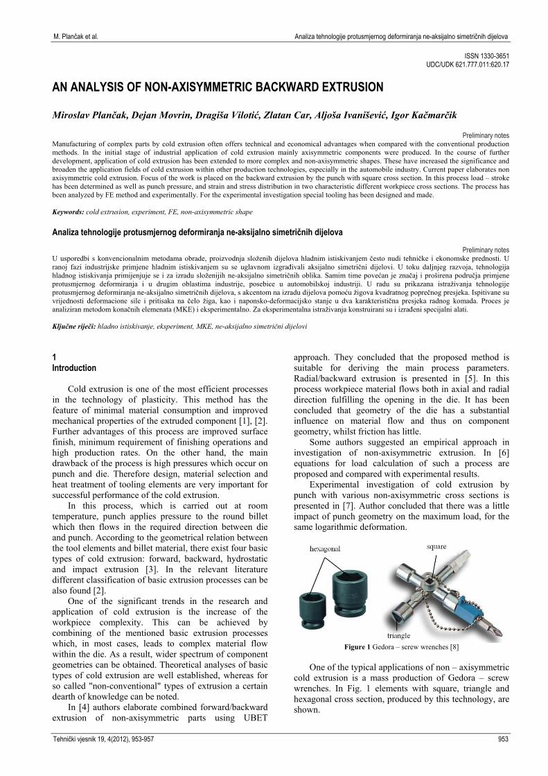
Experimental investigation of cold extrusion by punch with various non-axisymmetric cross sections is presented in [7]. Author concluded that there was a little impact of punch geometry on the maximum load, for the same logarithmic deformation.
Figure 1 Gedora – screw wrenches [8]
One of the typical applications of non – axisymmetric
cold extrusion is a mass production of Gedora – screw wrenches. In Fig. 1 elements with square, triangle and hexagonal cross section, produced by this technology, are shown.

An analysis of non-axisymmetric backward extrusion M. Plančak et al.
954 Technical Gazette 19, 4(2012), 953-957
Present paper is bounded to the experimental and numerical investigation of cold backward extrusion with the punch of square cross section. Relevant process data such as the load of extrusion, punch pressure, as well as the stress and strain distribution within the volume of the workpiece were determined by FE simulation and experimentally. 2 Numerical simulation
In Fig. 2 geometrical data of billet and final workpiece as well as dimensions of punch cross – section (a) with corresponding values of logarithmic deformation (φ) are presented.
p0
0lnAA
A
4
π2
0D
A
2p aA
a / mm φ
12,62 0,30 14,90 0,45 16,70 0,60 18,00 0,75
Figure 2 Geometry of billet and final workpiece
Numerical analysis was conducted by finite element
method, using commercial software Simufact Forming v.10. Constellation of billet and tooling elements at the beginning of the simulation is presented in Fig 3a.
Punch and die used in simulation were set as rigid bodies without heat conduction.
The dies and billet were modeled in CAD package Solid Edge and then imported to the Simufact Forming program. In order to reduce time as well as memory necessary for simulation, one quarter of the billet’s geometry was used. Hexahedral type of elements with 0,5 mm size was applied. For one quarter of specimen 28×28 mm number of the elements was 14.598 (Fig. 3b). Due to large deformation Overlay Hex mesher criterion was used. Boundary conditions were set by the use of symmetry planes. Two symmetry planes (I-I and III-III, Fig. 2) were drawn with 90° angle between them and their intersection presents central axis of the billet 28×28 mm (Fig. 2).
a) b) Figure 3 Simulation process: a) constellation between billet, punch and
die, b) Mesh system at the end of simulation
By 3D numerical simulation the information on stress
and strain distribution within the workpiece volume as well as load stroke diagram were obtained.
In the simulation and experimental investigation billets material was Ck10 with stress-strain curve obtained by Rastegajev test:
., MPa ,666 230e
(1)
Two different friction factors were used in
simulations and experiment: m = 0,20 (lubricated by oil) and m = 0,17 (phosphated + MoS2). Friction factors were obtained in ring compression test [9, 10].
Forming load and punch pressure in extrusion of non-axisymmetric workpieces can be obtained also analytically. According to [6], extrusion load is:
N, 0,6),(1,2e0 AF
(2)
where are: A0 – billet cross section, mm2 σe – effective stress, MPa φ – logarithmic strain, –
,lnp0
0
AA
A
(3)
Ap – punch cross section, mm2.
Average punch pressure is:
.A
Fp MPa ,
pave
(4)
3 Experimental investigation
For the experimental investigation special tooling was
designed and made. Four punches with different geometries according to data in Fig. 2 are shown in Fig. 4 and the punch with the extruded component is presented in Fig. 5. Backward extrusion was conducted on 630 kN Sack&Kiesselbach hydraulic press (Fig. 6). Two different

M. Plančak et al. Analiza tehnologije protusmjernog deformiranja ne-aksijalno simetričnih dijelova
Tehnički vjesnik 19, 4(2012), 953-957 955
lubricants are applied: mineral oil (friction factor: m = 0,2) and phosphated+MoS2 (friction factor: m = 0,17). Punch velocity was 0,5 mm/s.
Recording of load development during extrusion process was performed by means of load cell which was cemented on the experimental tolling.
Figure 4 Set of punches with square cross section
Figure 5 Punch and workpiece
Figure 6 Sack&Kiesselbach hydraulic press with experimental tooling
As results of experimental investigation recorded
load-stroke diagram for different punch geometries was obtained. These results are then compared with the analytical and numerical results.
4 Results with discussion
In this section results obtained by numerical
simulation, experiment and by analytical approach are presented, analyzed and compared.
4.1 Extrusion load (F)
Load-stroke characteristics for all four logarithmic
deformations (φ) obtained by experiment and simulation for the case m = 0,2 are given in Fig. 7. As it can be seen,
at the beginning of extrusion forming load rises steeply and after that load increases gradually till the end of the process, when it reaches its maximum value. Simulation results are somewhat higher than experimental. Maximum difference in load always appears at the end of the process and it is approximately 13 % to 18 %.
Figure 7 Load-stroke characteristics
Figure 8 Effect of logarithmic deformation on maximum extrusion load
Figure 9 Effect of logarithmic deformation on maximal load for steel
Effect of logarithmic deformation φ on the maximum
load, obtained analytically, experimentally and by numerical simulation is presented in Fig. 8. Analytical calculation was carried out by equation (2), suggested by [6]. Reasonable agreement exists between results obtained by three different methods.
An analysis of non-axisymmetric backward extrusion M. Plančak et al.
956 Technical Gazette 19, 4(2012), 953-957
Fig. 9 illustrates impact of friction factor m on maximum extrusion load Fmax for different logarithmic deformation φ. As it can be seen higher loads correspond to the higher value of friction factor (m = 0,2). Difference between loads obtained by friction factor m = 0,17 and m = 0,2 is between 3÷6 %, depending on logarithmic deformation φ.
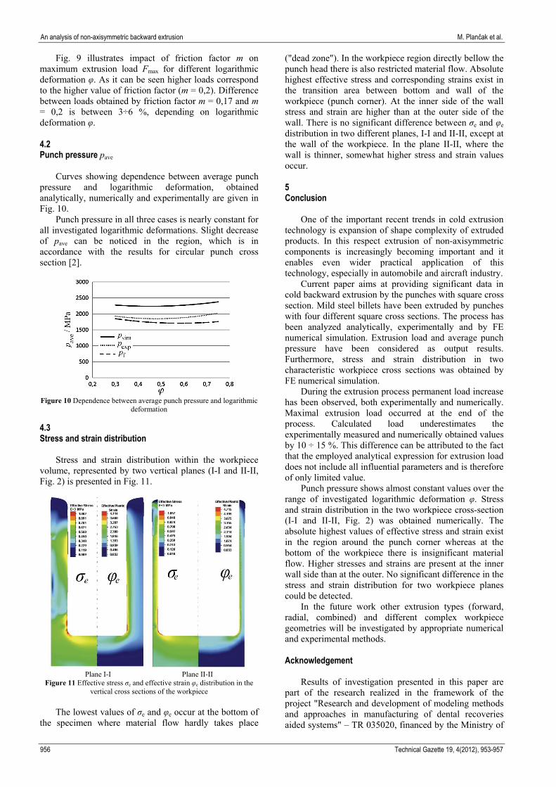
4.2 Punch pressure pave
Curves showing dependence between average punch
pressure and logarithmic deformation, obtained analytically, numerically and experimentally are given in Fig. 10.
Punch pressure in all three cases is nearly constant for all investigated logarithmic deformations. Slight decrease of pave can be noticed in the region, which is in accordance with the results for circular punch cross section [2].
Figure 10 Dependence between average punch pressure and logarithmic
deformation
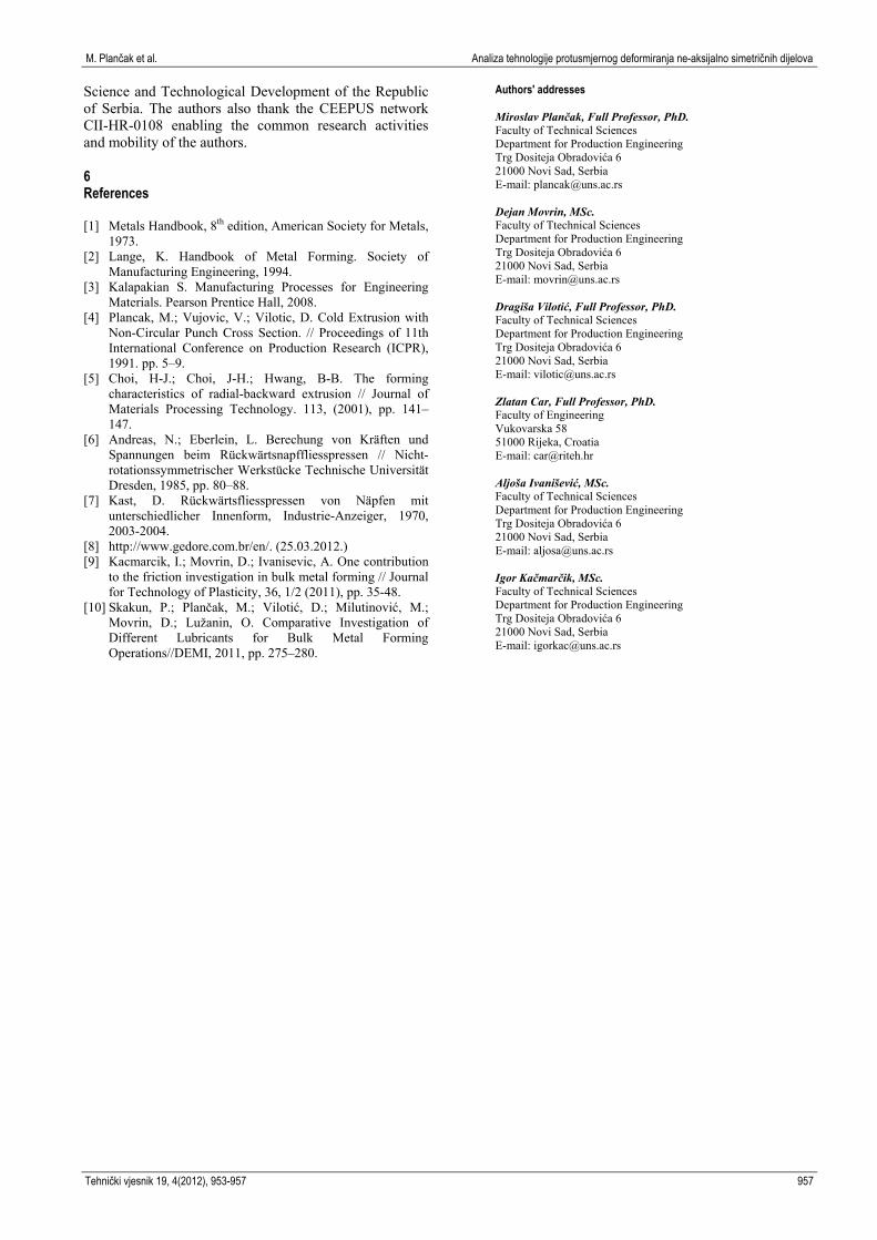
4.3 Stress and strain distribution
Stress and strain distribution within the workpiece
volume, represented by two vertical planes (I-I and II-II, Fig. 2) is presented in Fig. 11.
Plane I-I Plane II-II
Figure 11 Effective stress σe and effective strain φe distribution in the vertical cross sections of the workpiece
The lowest values of σe and φe occur at the bottom of
the specimen where material flow hardly takes place
("dead zone"). In the workpiece region directly bellow the punch head there is also restricted material flow. Absolute highest effective stress and corresponding strains exist in the transition area between bottom and wall of the workpiece (punch corner). At the inner side of the wall stress and strain are higher than at the outer side of the wall. There is no significant difference between σe and φe distribution in two different planes, I-I and II-II, except at the wall of the workpiece. In the plane II-II, where the wall is thinner, somewhat higher stress and strain values occur.
5 Conclusion
One of the important recent trends in cold extrusion
technology is expansion of shape complexity of extruded products. In this respect extrusion of non-axisymmetric components is increasingly becoming important and it enables even wider practical application of this technology, especially in automobile and aircraft industry.
Current paper aims at providing significant data in cold backward extrusion by the punches with square cross section. Mild steel billets have been extruded by punches with four different square cross sections. The process has been analyzed analytically, experimentally and by FE numerical simulation. Extrusion load and average punch pressure have been considered as output results. Furthermore, stress and strain distribution in two characteristic workpiece cross sections was obtained by FE numerical simulation.
During the extrusion process permanent load increase has been observed, both experimentally and numerically. Maximal extrusion load occurred at the end of the process. Calculated load underestimates the experimentally measured and numerically obtained values by 10 ÷ 15 %. This difference can be attributed to the fact that the employed analytical expression for extrusion load does not include all influential parameters and is therefore of only limited value.
Punch pressure shows almost constant values over the range of investigated logarithmic deformation φ. Stress and strain distribution in the two workpiece cross-section (I-I and II-II, Fig. 2) was obtained numerically. The absolute highest values of effective stress and strain exist in the region around the punch corner whereas at the bottom of the workpiece there is insignificant material flow. Higher stresses and strains are present at the inner wall side than at the outer. No significant difference in the stress and strain distribution for two workpiece planes could be detected.
In the future work other extrusion types (forward, radial, combined) and different complex workpiece geometries will be investigated by appropriate numerical and experimental methods.
Acknowledgement
Results of investigation presented in this paper are
part of the research realized in the framework of the project "Research and development of modeling methods and approaches in manufacturing of dental recoveries aided systems" – TR 035020, financed by the Ministry of
M. Plančak et al. Analiza tehnologije protusmjernog deformiranja ne-aksijalno simetričnih dijelova
Tehnički vjesnik 19, 4(2012), 953-957 957
Science and Technological Development of the Republic of Serbia. The authors also thank the CEEPUS network CII-HR-0108 enabling the common research activities and mobility of the authors.
6 References
[1] Metals Handbook, 8th edition, American Society for Metals,
1973. [2] Lange, K. Handbook of Metal Forming. Society of
Manufacturing Engineering, 1994. [3] Kalapakian S. Manufacturing Processes for Engineering
Materials. Pearson Prentice Hall, 2008. [4] Plancak, M.; Vujovic, V.; Vilotic, D. Cold Extrusion with
Non-Circular Punch Cross Section. // Proceedings of 11th International Conference on Production Research (ICPR), 1991. pp. 5–9.
[5] Choi, H-J.; Choi, J-H.; Hwang, B-B. The forming characteristics of radial-backward extrusion // Journal of Materials Processing Technology. 113, (2001), pp. 141–147.
[6] Andreas, N.; Eberlein, L. Berechung von Kräften und Spannungen beim Rückwärtsnapffliesspressen // Nicht-rotationssymmetrischer Werkstücke Technische Universität Dresden, 1985, pp. 80–88.
[7] Kast, D. Rückwärtsfliesspressen von Näpfen mit unterschiedlicher Innenform, Industrie-Anzeiger, 1970, 2003-2004.
[8] http://www.gedore.com.br/en/. (25.03.2012.) [9] Kacmarcik, I.; Movrin, D.; Ivanisevic, A. One contribution
to the friction investigation in bulk metal forming // Journal for Technology of Plasticity, 36, 1/2 (2011), pp. 35-48.
[10] Skakun, P.; Plančak, M.; Vilotić, D.; Milutinović, M.; Movrin, D.; Lužanin, O. Comparative Investigation of Different Lubricants for Bulk Metal Forming Operations//DEMI, 2011, pp. 275–280.
Authors' addresses Miroslav Plančak, Full Professor, PhD. Faculty of Technical Sciences Department for Production Engineering Trg Dositeja Obradovića 6 21000 Novi Sad, Serbia E-mail: [email protected] Dejan Movrin, MSc. Faculty of Ttechnical Sciences Department for Production Engineering Trg Dositeja Obradovića 6 21000 Novi Sad, Serbia E-mail: [email protected] Dragiša Vilotić, Full Professor, PhD. Faculty of Technical Sciences Department for Production Engineering Trg Dositeja Obradovića 6 21000 Novi Sad, Serbia E-mail: [email protected]
Zlatan Car, Full Professor, PhD. Faculty of Engineering Vukovarska 58 51000 Rijeka, Croatia E-mail: [email protected] Aljoša Ivanišević, MSc. Faculty of Technical Sciences Department for Production Engineering Trg Dositeja Obradovića 6 21000 Novi Sad, Serbia E-mail: [email protected] Igor Kačmarčik, MSc. Faculty of Technical Sciences Department for Production Engineering Trg Dositeja Obradovića 6 21000 Novi Sad, Serbia E-mail: [email protected]