An alternative boom design and welding technique to ...
8
Transcript of An alternative boom design and welding technique to ...

Scientia Iranica B (2017) 24(6), 2856{2863
Sharif University of TechnologyScientia Iranica
Transactions B: Mechanical Engineeringwww.scientiairanica.com
An alternative boom design and welding technique tominimize energy consumption during boom production
M. �Ozcana, M. Ya�gcia;� and V. Alverb
a. Faculty of Engineering and Architecture, Department of Electrical and Electronics Engineering, Necmettin Erbakan University,42060, Konya, Turkey.
b. MPG Makine Prod�uksiyon Grubu Research Engineer, Konya, Turkey.
Received 15 September 2015; received in revised form 3 June 2016; accepted 5 December 2016
KEYWORDSEnergy saving;Global warming;Welding;Metal bending;Welding oscillator.
Abstract. This paper presents an alternative boom design for mobile cranes and amethod to produce it for minimizing the energy consumption during its production. Themain change in the production of the crane booms is the shape of the booms. Normally,two symmetric boom parts are manufactured and, then, these parts are welded by twowelding processes. In the proposed design, only one part is manufactured and bendedat �rst. Therefore, one welding will be su�cient and a more energy-friendly process isachieved. With the proposed shape, the corner joints are eliminated when forming theboom shape, without any need to produce them beforehand. Single welding process isapplied to minimize energy consumption during the manufacturing of the boom; thus, thewelding quality becomes more important. In order to satisfy the welding quality, a weldingmanipulator is designed and manufactured. By using this welding manipulator, used ina closed area, and the applied �lter devices, the harmful gases are not released to theoperator and the environment. Finally, the energy and time required during the plasma-cutting process of boom parts are decreased by about 41% and the energy consumptionduring the welding process is decreased by about 53% compared to the traditional methods.
© 2017 Sharif University of Technology. All rights reserved.
1. Introduction
Production of hazardous gases, mainly CO2, SO2, andNOx, is one of the main reasons of global warming,which is one of the most important environmentalproblems of our time [1-5]. In addition to globalwarming, the gases released into the atmosphere causea disruption in ecological balance, which is consideredto be one of the most serious problems. Global warmingis increasing due to the increased energy consumption
*. Corresponding author. Tel.: +90 332 3252024E-mail addresses: [email protected] (M. �Ozcan);[email protected] (V. Alver)
doi: 10.24200/sci.2017.4310
day by day. On average, for each 1 kWh of energyproduced by a coal power plant, approximately 1 kgof CO2 is released to the atmosphere [6-8]. For thisreason, it is essential to use energy in the most e�cientway and to minimize the production of these gases.Nowadays, two very important research topics areminimization of energy consumption and productionof such gases by creating alternative solutions [9,10].
Mobile cranes perform useful material-handlingservices around the world. They are commonly usedfor carrying, uploading, and downloading of industrialmaterials. One of the most important parts of themobile cranes is booms, which are used for carryingthe loads. Moreover, the exible shape of mobile cranesprovides them with e�ciency and safety.
In this paper, an alternative boom design tech-

M. �Ozcan et al./Scientia Iranica, Transactions B: Mechanical Engineering 24 (2017) 2856{2863 2857
nique to minimize the energy consumption and haz-ardous gas formation during the production of boomsfor mobile cranes is searched. Due to the complexityand high price of the large-volume metal productionprocess, di�erent metal pieces are jointed using a vari-ety of welding methods [11-14]. Some welding methodsapplied in industrial purposes are corner joints, edgejoints, lap joints, T-joints, and butt joints [15].
Laser welding method provides the best perfor-mance, but with low e�ciency value; therefore, toreduce energy consumption and increase the e�ciency,traditional welding methods such as arc welding arecommonly preferred for joining metal pieces in theindustry, especially in the manufacturing industry forjoining the metal pieces thicker than 10 mm as itrequires a vast amount of material and electricity [16].
Arc welding is the most widely used classicalwelding method and it has been used in the industryfor a very long time [17]. The major advantages of thearc welding method are its non-complexity, low cost, exibility for di�erent purposes in jointing the metalpieces, and continuous integration due to technologicalimprovements [18]. Because of these advantages, thiswelding method is still used in today's productionprocesses; even it can be adapted to the automationtechnology [19-21]. The arc welding method can beapplied as well with a welding oscillator instead of amanual operator due to continuous improvements inthe automated processes. The experience and perfor-mance of the operator have a high impact on the qualityof the manually performed welding processes. Usingthe welding oscillator has many advantages such ashigh quality welding performance, reduced productiontime and cost of labor, possibility of performing variantwelding shapes that are not possible to ful�ll by anoperator, minimization of errors on the operator's side,and the lowest risk of work accidents [18].
Konya, located in Turkey, can be considered as
the center for mobile crane manufacturing companies.These companies use the traditional boom manufactur-ing techniques such as jointing two steel pieces with twowelding operations performed by an operator or usingrobotic manipulator. These traditional techniques ne-cessitate four corner joint creation steps before weldingthe two metal pieces.
In the proposed alternative technique (patentpending), only one metal piece is bended to form theboom shape. The main advantage of this technique isdecrease in the number of welding steps from two toone. However, in addition to this obvious advantage,the second advantage of this technique is the elimina-tion of the corner joint steps as corner joints are formednaturally while bending the metal pieces.
One single welding step necessitates a high qualitywelding. In order to ensure the quality of the weldingprocess, we have designed and manufactured a speci�cwelding manipulator [18]. With the help of thismanipulator, a high quality and automated weldingprocess is achieved, which also helps to minimize therisks of the manual operation mistakes for the humansafety and environmental protection [18,21,22].
The rest of the article is organized as follows:Section 2 explains the alternative boom design andSection 3 gives the details of the design of the weldingmanipulator. Results and discussions are given inSection 4, and Section 5 provides the conclusions.
2. Alternative boom design
Traditionally, booms for mobile cranes are manufac-tured by jointing two steel pieces with two welding op-erations performed by an operator. In this traditionaltechnique, two steel pieces with appropriate dimensionsare plasma-cut from the steel plate at �rst. Table 1 liststhe details of this cutting step, taking a knuckle boommobile crane as an example, which has 33 ton-meter
Table 1. Cutting data of the plate S690QL due to lower-upper pieces sizes of booms.
Weldedbooms
Thickness(mm)
Width(mm)
Length(mm)
Plasmaspeed
(mm/min)
Plasmatime*
(s)
Consumedenergy**(kWh)
Knuckle boom 10 840 2650 2600 162 1,35001. Extension 10 775 2750 2600 164 1,36672. Extension 10 715 2850 2600 165 1,37503. Extension 10 650 2950 2600 167 1,39174. Extension 8 600 3050 3300 135 1,12505. Extension 8 545 3150 3300 136 1,13346. Extension 8 500 3250 3300 138 1,1500
Total (The values are doubled because there are two pieces) 2134 17.7836* When the plasma current is 130 A.** The power of the plasma cutting machine is 30 kW (when the current is 130 A).
2858 M. �Ozcan et al./Scientia Iranica, Transactions B: Mechanical Engineering 24 (2017) 2856{2863
Table 2. The mechanical properties of the used quenched and tempered structural steel, S690QL (Steel Number:1.8931)[23].
Designation Mechanical properties (at 20�C)
Nominal thickness (mm) � 3 � 50 � 50 � 100 � 100 � 150Yield strength Reh. (MPa, Min.) 690 650 630Tensile strength Rm. (MPa) 770/940 760/930 710/900Min.% elongation after fracture 14 14 14
Table 3. The chemical composition of the used quenched and tempered structural steel, S690QL [23].
Element Percentage Element Percentage Element Percentage
C 0.20 N 0.015 Nb� 0.06Si 0.80 B 0.0050 Ni 2.0
Mn 1.70 Cr 1.50 Ti� 0.05P 0.025 Cu 0.50 V� 0.12S 0.015 Mo 0.70 Zr� 0.15
*At least 0.015% of grain-re�ning elements present.
Figure 1. (a) Photos of the press brake used for boombending step. (b) Control panel of the press brake.
lifting capacity, maximum boom extension length of15 m, and 6 boom extensions. For this example,quenched and tempered structural steel of S690QLplate is considered [23].
The properties of this material are summarizedin Tables 2 and 3. As two steel pieces will be cut toform the boom, the values should be doubled to �ndthe total energy consumption.
The required boom shape is achieved by pressingthe plasma-cut pieces (Figure 1). In order to jointthese two steel plates, two corner joints for each metalplate must be created at the boundaries. These cornerjoints are created using oxygen-acetylene cutting torchFigure 2(a). The shape and angle of the corner jointsare the factors a�ecting the quality of the weld. Theopening angle of the corner joints is chosen to be 45�in order to ensure the best welding quality [24].
After the creation of corner joints, two steel piecesare welded together by an operator using gas metal arcwelding Figure 2(b). The welding process done in thisway takes very long time and the desired shape and sizeof the booms are di�cult to obtain because of using
Figure 2. Traditional boom production: (a) Boom cornerjoints and (b) welded joints [25].
two steel pieces and the excessive deformation duringmanual welding. As the average length of the booms isa big number 3 m, eliminating excessive deformationsof the weld is impossible.
In the alternative boom design proposed in thiswork (patent pending), several energy consuming stepsof the traditional boom manufacturing are eliminated.The details of the alternative design and the way toperform it are as follows: A single steel piece is plasma-cut from the steel plate at �rst, which is large enoughto form the boom shape after bending.
Table 4 lists the details of this cutting process,taking the same knuckle crane as that in the example.This single piece is again bent according to the size ofthe boom in the press brake Figure 3(a). However,after the bending process of the single metal sheetbased on the boom shape, the corner joints are formedautomatically as given in Figure 3(b). The corner jointcreation steps are eliminated; the last step is to weldthis single metal sheet to itself with a single weldingprocess with the help of the welding manipulatordesigned and implemented in this study [25].

M. �Ozcan et al./Scientia Iranica, Transactions B: Mechanical Engineering 24 (2017) 2856{2863 2859
Table 4. The values of plate cutting for the booms obtained from a single piece.
Weldedbooms
Thickness(mm)
Width(mm)
Length(mm)
Plasmaspeed
(mm/min)
Plasmatime*
(s)
Consumptionenergy**(kWh)
Knuckle boom 10 1680 2650 2600 201 1,67501. Extension 10 1550 2750 2600 199 1,65932. Extension 10 1430 2850 2600 198 1,65103. Extension 10 1300 2950 2600 196 1,63344. Extension 8 1200 3050 3300 156 1,30105. Extension 8 1090 3150 3300 155 1,29176. Extension 8 1000 3250 3300 156 1,3010
Total (The values are doubled because there are two pieces) 1261 10,5124* When the plasma current is 130 A;** The power of the plasma cutting machine is 30 kW (when the current is 130 A).
Figure 3. (a) Bending dimensions of the sample boom[25]. (b) Corner joint after bending.
As can be seen from Tables 1 and 4, the al-ternative design has two main advantages over thetraditional method. First, the welding time and theconsumed energy for the welding processes are reduced.Moreover, cutting the steel pieces from the steel platewill consume less energy and time. Second, the cornerjoint creation steps are completely eliminated; thus, thetotal energy consumption to manufacture the booms isreduced signi�cantly.
3. Design of the welding manipulator
Due to two important reasons, a manipulator is de-signed during this study. First, as the booms will have
a single welded line (the boom shape will not be 100%symmetric due to this welded side), this single weldedline should be as high quality as possible. The qualityof the welding performed by an operator will not beas good as that of the welding done by an automaticmachine. Second, operators will not be exposed tothe harmful gases generated during the welding oper-ation. Furthermore, these gases can be �ltered usingrelated apparatus so that the environment protectionis achieved. The block diagram of the system explainedabove is shown in Figure 4.
The MIG method chosen for the boom weldingof this study is one of the most suitable arc weldingmethods as it is easy and cheap and does not leaveany residues. The speci�cations of the MIG weldingmachine chosen for the welding process are givenin Table 5. Similarly, Table 6 lists the technicalspeci�cations of the welding oscillator [18].
The ow diagram of the system operation is givenin Figure 5. The operation of the system can besummarized simply as follows: Initially, the boomto be welded is �xed. The torch is brought to thestarting point of welding. Two-axis movement controlautomation operates the torch. To achieve a highquality welding, it is best to use a constant speed.Welding current, welding wire, and wire feed speed arechosen according to the needs of the required welding
Figure 4. System con�guration of welding manipulator.
2860 M. �Ozcan et al./Scientia Iranica, Transactions B: Mechanical Engineering 24 (2017) 2856{2863
Table 5. Technical speci�cations of the GKM500-2WMIG arc welding machine [26].
Item Speci�cations
Input voltage 3 phase, 380 V, 50-60 HzPower 27.5 kVAOpen circuit voltage 16-57 VCurrent range 40 A{500 ADuty cycle 60%, 500 A; 100%, 400 AProtection class IP 23Wire feeder 0.8, 1, 1.2, 1.6Wire type Fe{Flux cored
Table 6. Technical speci�cations of the GKM500-2WMIG arc welding machine [26].
Item Speci�cations
Right width Maximum 30 mm (step 0.1 mm)Left width Maximum 30 mm (step 0.1 mm)Sweeping angle � 30�
Left speed 0 � 4 m/min (step 0.1 m/min)Right speed 0 � 4 m/min (step 0.1 m/min)Stop time on the left 0 � 6.0 s (step 0.1 s)Stop time on the right 0 � 6.0 s (step 0.1 s)Stop time on the center 0 � 6.0 s (step 0.1 s)
Table 7. Boom welding parameters depending on thethickness of the work-piece.
Item Speci�cationsThickness of the piece (mm) 10-8
The consumption rate of thewire feeder (mm/s)
19-17
Welding speed (mm/s) 4.5-7.5Diameter of the wire (mm) 1.2-1.2Used current (A) 280-230Protective gas CO2-Ar (L/min) 16-15
process. Using a protective gas during the weldingprocess is of great importance for the welding quality.During the welding process, the ow of the protectivegas is controlled. The parameter of wire feeder speedis adjusted on the speed control unit. The selectedwelding parameters depending on the thickness of theboom are shown in Table 7.
Figure 6 shows the designed welding manipulatorand includes the initial prototype Figure 6(a), the �nalprototype Figure 6(b), and the extra precautions takento minimize the bending of the boom shape due totemperature variations after the welding Figure 6(c).
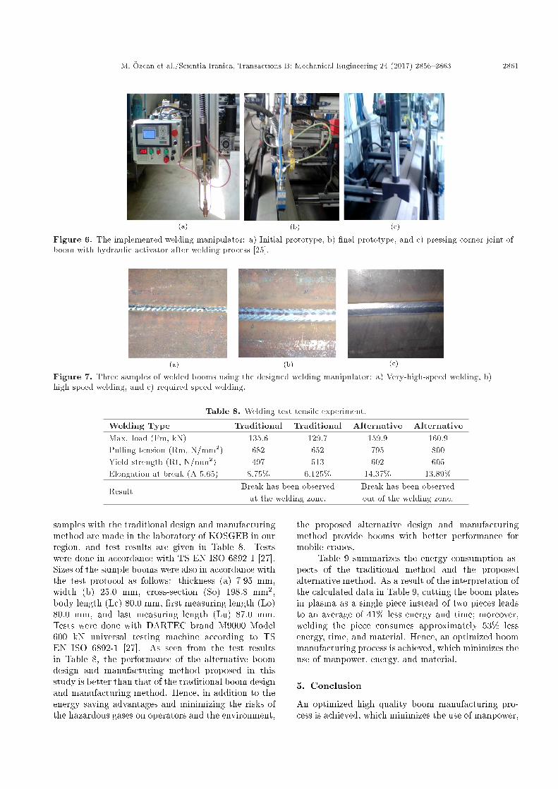
Figure 7 shows the sample welded booms usingthe designed welding manipulator; the �rst with veryfast welding speed Figure 7(a); then, with fast welding
Figure 5. Flow diagram of welding manipulator.
speed Figure 7(b); and, �nally, with the requiredwelding speed Figure 7(c). These booms are weldedunder approximately 20 psi Ar and CO2 gases, whichprevent oxidation problems. 8 mm thick pieces arewelded using 390 A of current and 10 mm thick piecesare welded using 410 A of current with 3 passes.The welding operation is carried out in a closed andair �ltered chamber to minimize the e�ects of thehazardous gases generated during the operation on theoperators and the environment.
4. Results and discussions
Welding tests of boom samples designed and manu-factured with the alternative method and the boom
M. �Ozcan et al./Scientia Iranica, Transactions B: Mechanical Engineering 24 (2017) 2856{2863 2861
Figure 6. The implemented welding manipulator: a) Initial prototype, b) �nal prototype, and c) pressing corner joint ofboom with hydraulic activator after welding process [25].
Figure 7. Three samples of welded booms using the designed welding manipulator: a) Very-high-speed welding, b)high-speed welding, and c) required-speed welding.
Table 8. Welding test tensile experiment.
Welding Type Traditional Traditional Alternative AlternativeMax. load (Fm, kN) 135.6 129.7 159.9 160.9Pulling tension (Rm, N/mm2) 682 652 795 800Yield strength (Rt, N/mm2) 497 513 602 605Elongation at break (A 5.65) 8.75% 6.125% 14.37% 13.89%
Result Break has been observedat the welding zone.
Break has been observedout of the welding zone.
samples with the traditional design and manufacturingmethod are made in the laboratory of KOSGEB in ourregion, and test results are given in Table 8. Testswere done in accordance with TS EN ISO 6892-1 [27].Sizes of the sample booms were also in accordance withthe test protocol as follows: thickness (a) 7.95 mm,width (b) 25.0 mm, cross-section (So) 198.8 mm2,body length (Lc) 80.0 mm, �rst measuring length (Lo)80.0 mm, and last measuring length (Lu) 87.0 mm.Tests were done with DARTEC brand M9000 Model600 kN universal testing machine according to TSEN ISO 6892-1 [27]. As seen from the test resultsin Table 8, the performance of the alternative boomdesign and manufacturing method proposed in thisstudy is better than that of the traditional boom designand manufacturing method. Hence, in addition to theenergy saving advantages and minimizing the risks ofthe hazardous gases on operators and the environment,
the proposed alternative design and manufacturingmethod provide booms with better performance formobile cranes.
Table 9 summarizes the energy consumption as-pects of the traditional method and the proposedalternative method. As a result of the interpretation ofthe calculated data in Table 9, cutting the boom platesin plasma as a single piece instead of two pieces leadsto an average of 41% less energy and time; moreover,welding the piece consumes approximately 53% lessenergy, time, and material. Hence, an optimized boommanufacturing process is achieved, which minimizes theuse of manpower, energy, and material.
5. Conclusion
An optimized high quality boom manufacturing pro-cess is achieved, which minimizes the use of manpower,

2862 M. �Ozcan et al./Scientia Iranica, Transactions B: Mechanical Engineering 24 (2017) 2856{2863
Table 9. Comparison of the conventional and the new boom manufacturing methods [25].
WeldedBooms
Conventional boomproduction method
New boomproduction method
Weldingtime (s)
Welding energyconsumption
(Kwh)
Usedweldingwire (m)
Weldingtime (s)
Welding energyconsumption
(Kwh)
Usedweldingwire (m)
Knuckle 1930 9.65 185 900 4.500 921.extension 2010 10.0503 196 940 4.700 952.extension 2080 10.4004 206 975 4.875 983.extension 2150 10.7502 209 1005 5.025 1024.extension 1526 7.2061 135 713 3.3669 655.extension 1576 7.4422 147 735 3.4708 676.extension 1630 7.6972 145 762 3.5983 70
Total 12902 63.1964 1223 6030 29.5361 589
energy, and material. It is shown that the energyand time required during the plasma-cutting processof boom parts are decreased by about 41%, and theenergy consumption during the welding process isdecreased by about 53% compared to the traditionalmethods. Thus, 41% savings can be achieved with theproposed method.
For further studies, this paper will provide a guideto the related industry to consider their productionline, as signi�cant amounts of energy, manpower, andmaterial usage can be saved with alternative designand manufacturing methods. In Konya, which is oneof the most important centers regarding mobile cranemanufacturing in Turkey, approximately, 49 MWhenergy can be saved and 49 ton CO2 gas release tothe environment can be prevented in the welding andcutting processes annually. Material and manpowersavings as well as minimizing hazardous gas productionwill increase the importance of this study. This study isan example which shows that industry can create suchalternative production methods to minimize the pro-duction of hazardous gases and the consumed energyin order to control and minimize the global warmingissue.
Acknowledgment
This study was supported by TUB�ITAK 1501 - Projectnumber 3090646 in the mobile crane industry withthe capacity of 120 tons and 3 meters by NecmettinErbakan University Scienti�c Research Projects O�ce.
References
1. Florides, G.A. and Christodoulides, P. \Global warm-ing and carbon dioxide through sciences", Environ-ment International, 35(2), pp. 390-401 (2009).
2. G�uven�c, U., S�onmez, Y., Duman, S. and Y�or�ukeren N.
\Combined economic and emission dispatch solutionusing gravitational search algorithm", Scientia Iranica,19(6), pp. 1754-1762
3. Youse�, M., Khoramivafa, M. and Mondani, F. \In-tegrated evaluation of energy use, greenhouse gasemissions and global warming potential for sugar beet(Beta vulgaris) agroecosystems in Iran", AtmosphericEnvironment, 92, pp. 501-505 (2014).
4. Winter, R.A. \Innovation and the dynamics of globalwarming", Journal of Environmental Economics andManagement, 68(1), pp. 124-140 (2014).
5. Nejat, P., Jomehzadeh, F., Taheri, M.M., Gohari, M.and Majid, M.Z.A. \A global review of energy con-sumption, CO2 emissions and policy in the residentialsector (with an overview of the top ten CO2 emit-ting countries)", Renewable and Sustainable EnergyReviews, 43, pp. 843-862 (2015).
6. Akorede, M.F., Hizam, H., Ab Kadir, M.Z.A., Aris, I.and Buba, S.D. \Mitigating the anthropogenic globalwarming in the electric power industry", Renewableand Sustainable Energy Reviews, 16(5), pp. 2747-2761(2012).
7. Yuksel, I. \Global warming and environmental bene�tsof hydroelectric for sustainable energy in Turkey",Renewable and Sustainable Energy Reviews, 16(6), pp.3816-3825 (2012).
8. Anisura, M.R., Mahfuza, M.H., Kibriaa, M.A. andSaidura, R. \Curbing global warming with phasechange materials for energy storage", Renewable andSustainable Energy Reviews, 18, pp. 23-30 (2013).
9. Shrivastava, A., Krones, M. and Pfe�erkorn, F.E.\Comparison of energy consumption and environmen-tal impact of friction stir welding and gas metal arcwelding for aluminum", CIRP Journal of Manufactur-ing Science and Technology, 9, pp. 159-168 (2015).
10. Mose, C. and Weinert, N. \Process chain evalua-tion for an overall optimization of energy e�ciencyin manufacturing{The welding case", Robotics and

M. �Ozcan et al./Scientia Iranica, Transactions B: Mechanical Engineering 24 (2017) 2856{2863 2863
Computer-Integrated Manufacturing, 34, pp. 44-51(2015).
11. Kim, I.S., Son, J.S. and Yarlagadda, P.K.D.V. \Astudy on the quality improvement of robotic GMAwelding process", Robotics and Computer-IntegratedManufacturing, 19(6), pp. 567-572 (2003).
12. Guen, E.L., Fabbro, R., Carin, M., Coste, F. andMasson, P.L. \Analysis of hybrid Nd:YAG laser-MAGarc welding processes", Optics & Laser Technology,43(7), pp. 1155-1166 (2011).
13. Gua, X., Lia, H., Yanga, L. and Gaob, Y. \Couplingmechanism of laser and arcs of laser twin-arc hybridwelding and its e�ect on welding process", Optics &Laser Technology, 48, pp. 246-253 (2013).
14. Sidhar, H., Martinez, N.Y., Mishra, R.S. and Silvanus,J. \Friction stir welding of Al-Mg-Li 1424 alloy",Materials & Design, 106, pp. 146-152 (2016).
15. Wu, L., Cheon, J., Kiran, D.V. and Na, S. \CFDsimulations of GMA welding of horizontal �llet jointsbased on coordinate rotation of arc models", Journalof Materials Processing Technology, 231, pp. 221-238(2016).
16. Tarak�cio�glu, N. and �Ozcan, M. Lasers and MaterialProcessing Application 1st ed. pp. 179-200, Atlas Press,Istanbul, Turkey (2004).
17. Vural, M. \Welding processes and technologies", Ref-erence Module in Materials Science and MaterialsEngineering Comprehensive Materials Processing, 6,pp. 3-48 (2014).
18. �Ozcan, M. \Design and realization of a welding oscil-lator" , Turk. J. Elec. Eng. & Comp. Sci., 22, pp.1219-1229 (2014).
19. Erden, M.S. and Maric0, B. \Assisting manual weldingwith robot", Robotics and Computer-Integrated Man-ufacturing, 27(4), pp. 818-828 (2011).
20. Kim, I.S., Son, J.S., Lee, S.H. and Yarlagadda,P.K.D.V. \Optimal design of neural networks for con-trol in robotic arc welding", Robotics and Computer-Integrated Manufacturing 20(1), pp. 57-63 (2004).
21. Hong, T.S., Ghobakhloo, M. and Khaksar, W.\Robotic welding technology", Reference Module inMaterials Science and Materials Engineering fromComprehensive Materials Processing, 6, pp. 77-99(2014).
22. Popovic0, O., Cvetkovic0a, R.P., Burzic0, M., Lukic0,U. and Beljic0, B. \Fume and gas emission during arcwelding: Hazards and recommendation", Renewableand Sustainable Energy Reviews, 37, pp. 509-516(2014).
23. http://www.masteel.co.uk/s690-ql.htm Accessed: De-cember (2015).
24. Unt, A., Poutiainen, I. and Salminen, A., \In uenceof �ller wire feed rate in laser-arc hybrid welding of T-butt Joint in shipbuilding steel with di�erent opticalsetups", Physics Procedia (15th Nordic Laser MaterialsProcess. Conf., Nolamp 15), 78, pp. 45-52 (2015).
25. �Ozcan, M., Endiz, M.S. and Alver, V., \A new ap-proach to the boom welding technique by determiningseam pro�le tracking", Int'l Journal of Advances inMechanical & Automobile Engg. (IJAMAE), 2(1), pp.31-34 (2015).
26. Gedikwelding, http://www.gedikwelding.com/product/gkm- 500-2w-welding-machines, Accessed: March,(2016).
27. Standart of TS EN ISO 6892-1 \Metallic Materials forTensile Testing" (2011).
Biographies
Muciz �Ozcan was born in Konya, Turkey, in 1966.He received the BS degree from Anadolu University,Eskisehir, Turkey, in 1989; the MS and PhD degreesfrom Sel�cuk University, Konya, Turkey, in 1996 and2003, respectively. He is currently associate professor inthe Electrical and Electronics Engineering Departmentof Necmettin Erbakan University, Turkey. His researchinterests include automation, electrical machines, sen-sors, laser electronics, and energy e�ciency. He isthe author or co-author of several papers published inscienti�c journals or conference proceedings.
Mustafa Ya�gci was born in Konya, Turkey, in 1963.He received the BS degree from Marmara University,Istanbul, Turkey, in 1984; the MS degree from GaziUniversity, Ankara, Turkey, in 1994; and the PhDdegree from Sel�cuk University, Konya, Turkey, in 2005.He is currently Assistant Professor in the Electricaland Electronics Engineering Department of NecmettinErbakan University, Turkey. His research interests in-clude electrical machines and driving circuits, harmon-ics of transformers, power electronics, and photovoltaicpower plants. He is the author or co-author of severalpapers published in scienti�c journals or conferenceproceedings.
Veysel Alver was born in Antalya, Turkey, in 1976.He received the BS and Ms degrees from Sel�cuk Uni-versity, Konya, Turkey, in 1998 and 2012, respectively.He is research engineer in MPG Machinery ProductionGroup Inc. Co. His research interests include produc-tion of knuckle boom mobile cranes, telescopic boommobile cranes, tree trans planters, etc.