Basic Data Structures for IP lookups and Packet Classification

31
CHAPTER 2
An Algorithm for Performing
Routing Lookups in Hardware
1 Introduction
This chapter describes a longest prefix matching algorithm to perform fast IPv4 route
lookups in hardware. The chapter first presents an overview of previous work on IP look-
ups in Section 2. As we will see, most longest prefix matching algorithms proposed in the
literature are designed primarily for implementation in software. They attempt to optimize
the storage requirements of their data structure, so that the data structure can fit in the fast
cache memories of high speed general purpose processors. As a result, these algorithms do
not lend themselves readily to hardware implementation.
Motivated by the observation in Section 3 of Chapter 1 that the performance of a
lookup algorithm is most often limited by the number of memory accesses, this chapter
presents an algorithm to perform the longest matching prefix operation for IPv4 route
lookups in hardware in two memory accesses. The accesses can be pipelined to achieve
one route lookup every memory access. With 50 ns DRAM, this corresponds to approxi-
mately packets per second — enough to forward a continuous stream of 64-byte
packets arriving on an OC192c line.
20 106×

An Algorithm for Performing Routing Lookups in Hardware 32
The lookup algorithm proposed in this chapter achieves high throughput by using pre-
computation and trading off storage space with lookup time. This has the side-effect of
increased update time and overhead to the central processor, and motivates the low-over-
head update algorithms presented in Section 5 of this chapter.
1.1 Organization of the chapter
Section 2 provides an overview of previous work on route lookups and a comparative
evaluation of the different routing lookup schemes proposed in literature. Section 3
describes the proposed route lookup algorithm and its data structure. Section 4 discusses
some variations of the basic algorithm that make more efficient use of memory. Section 5
investigates how route entries can be quickly inserted and removed from the data struc-
ture. Finally, Section 6 concludes with a summary of the contributions of this chapter.
2 Background and previous work on route lookup algorithms
This section begins by briefly describing the basic data structures and algorithms for
longest prefix matching, followed by a description of some of the more recently proposed
schemes and a comparative evaluation (both qualitative and quantitative) of their perfor-
mance. In each case, we provide only an overview, referring the reader to the original ref-
erences for more details.
2.1 Background: basic data structures and algorithms
We will use the forwarding table shown in Table 2.1 as an example throughout this
subsection. This forwarding table has four prefixes of maximum width 5 bits, assumed to
have been added to the table in the sequence P1, P2, P3, P4.

An Algorithm for Performing Routing Lookups in Hardware 33
2.1.1 Linear search
The simplest data structure is a linked-list of all prefixes in the forwarding table. The
lookup algorithm traverses the list of prefixes one at a time, and reports the longest match-
ing prefix at the end of the traversal. Insertion and deletion algorithms perform trivial
linked-list operations. The storage complexity of this data structure for prefixes is
. The lookup algorithm has time complexity and is thus too slow for practical
purposes when is large. The insertion and deletion algorithms have time complexity
, assuming the location of the prefix to be deleted is known.
The average lookup time of a linear search algorithm can be made smaller if the pre-
fixes are sorted in order of decreasing length. For example, with this modification, the pre-
fixes of Table 2.1 would be kept in the order P4, P3, P1, P2; and the lookup algorithm
would be modified to simply stop traversal of the linked-list the first time it finds a match-
ing prefix.
2.1.2 Caching of recently seen destination addresses
The idea of caching, first used for improving processor performance by keeping fre-
quently accessed data close to the CPU [34], can be applied to routing lookups by keeping
recently seen destination addresses and their lookup results in aroute-cache. A full lookup
TABLE 2.1. An example forwarding table with four prefixes. The prefixes are written in binary with a ‘*’ denotingone or more trailing wildcard bits — for instance, 10* is a 2-bit prefix.
Prefix Next-hop
P1 111* H1
P2 10* H2
P3 1010* H3
P4 10101 H4
N
O N( ) O N( )
N
O 1( )

An Algorithm for Performing Routing Lookups in Hardware 34
(using some longest prefix matching algorithm) is now performed only if the incoming
destination address is not already found in the cache.
Cache hit rate needs to be high in order to achieve a significant performance improve-
ment. For example, if we assume that a full lookup is 20 times slower than a cache lookup,
the hit rate needs to be approximately 95% or higher for a performance improvement by a
factor of 10. Early studies [22][24][77] reported high cache hit rates with large parallel
caches: for instance, Partridge [77] reports a hit rate of 97% with a cache of size 10,000
entries, and 77% with a cache of size 2000 entries. Reference [77] suggests that the cache
size should scale linearly with the increase in the number of hosts or the amount of Inter-
net traffic. This implies the need for exponentially growing cache sizes. Cache hit rates are
expected to decrease with the growth of Internet traffic because of decreasing temporal
locality [66]. The temporal locality of traffic is decreasing because of an increasing num-
ber of concurrent flows at high-speed aggregation points and decreasing duration of a
flow, probably because of an increasing number of short web transfers on the Internet.
A cache management scheme must decide which cache entry to replace upon addition
of a new entry. For a route cache, there is an additional overhead of flushing the cache on
route updates. Hence, low hit rates, together with cache search and management overhead,
may even degrade the overall lookup performance. Furthermore, the variability in lookup
times of different packets in a caching scheme is undesirable for the purpose of hardware
implementation. Because of these reasons, caching has generally fallen out of favor with
router vendors in the industry (see Cisco [120], Juniper [126] and Lucent [128]) who tout
fast hardware lookup engines that do not use caching.

An Algorithm for Performing Routing Lookups in Hardware 35
2.1.3 Radix trie
A radix trie, or simply a trie,1 is a binary tree that has labeled branches, and that is tra-
versed during a search operation using individual bits of the search key. The left branch of
a node is labeled ‘0’ and the right-branch is labeled ‘1.’ A node, , represents a bit-string
formed by concatenating the labels of all branches in the path from the root node to . A
prefix, , is stored in the node that represents the bit-string . For example, the prefix
is stored in the left child of the root node.
1. The name trie comes from retrieval, but is pronounced “try”. See Section 6.3 on page 492 of Knuth [46] for moredetails on tries.
P1
P2
P4
P3
1
0
0
1
1
11
Figure 2.1 A binary trie storing the prefixes of Table 2.1. The gray nodes store pointers to next-hops. Notethat the actual prefix values are never stored since they are implicit from their position in the trie and can berecovered by the search algorithm. Nodes have been named A, B, ..., H in this figure for ease of reference.
F
D
B
A
C
E
G
H
next-hop-ptr (if prefix present)
left-ptr right-ptr
Trie node
v
v
p p 0*

An Algorithm for Performing Routing Lookups in Hardware 36
A trie for -bit prefixes has a maximum depth of nodes. The trie for the example
forwarding table of Table 2.1 is shown in Figure 2.1.
The longest prefix search operation on a given destination address proceeds bitwise
starting from the root node of the trie. The left (right) branch of the root node is taken if
the first bit of the address is ‘0’ (‘1’). The remaining bits of the address determine the path
of traversal in a similar manner. The search algorithm keeps track of the prefix encoun-
tered most recently on the path. When the search ends at a null pointer, this most recently
encountered prefix is the longest prefix matching the key. Therefore, finding the longest
matching prefix using a trie takes memory accesses in the worst case, i.e., has time
complexity .
The insertion operation proceeds by using the same bit-by-bit traversal algorithm as
above. Branches and internal nodes that do not already exist in the trie are created as the
trie is traversed from the root node to the node representing the new prefix. Hence, inser-
tion of a new prefix can lead to the addition of at most other trie nodes. The storage
complexity of a -bit trie with prefixes is thus .1
An IPv4 route lookup operation is slow on a trie because it requires up to 32 memory
accesses in the worst case. Furthermore, a significant amount of storage space is wasted in
a trie in the form of pointers that are null, and that are onchains — paths with 1-degree
nodes, i.e., that have only one child (e.g., path BCEGH in Figure 2.1).
Example 2.1:Given an incoming 5-bit address 10111 to be looked up in the trie of Figure 2.1,the longest prefix matching algorithm takes the path ABCE before reaching a nullpointer. The last prefix encountered on this path, prefix P2 (10*) in node C, is thedesired longest matching prefix.
1. The total amount of space is, in fact, slightly less than because prefixes share trie branches near the root node.
W W
W
O W( )
W
W N O NW( )
NW
An Algorithm for Performing Routing Lookups in Hardware 37
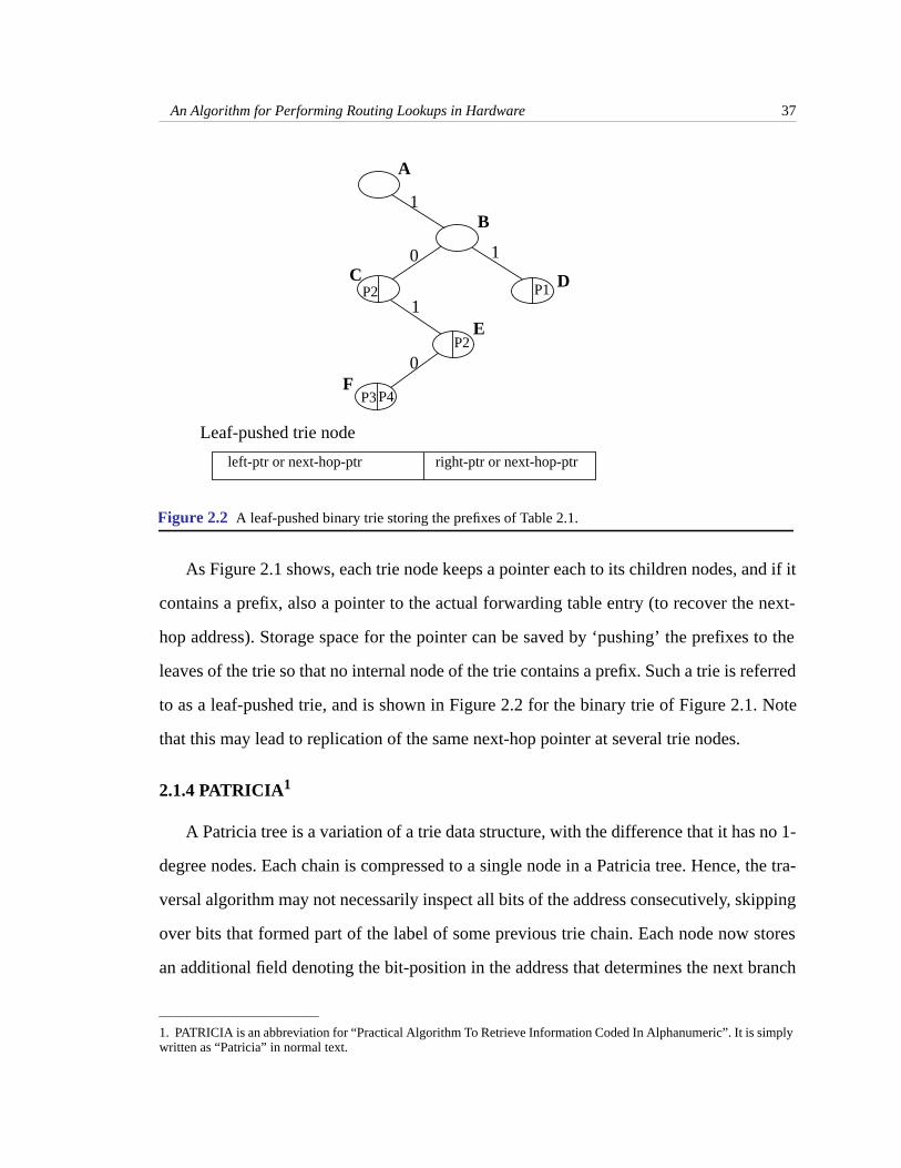
As Figure 2.1 shows, each trie node keeps a pointer each to its children nodes, and if it
contains a prefix, also a pointer to the actual forwarding table entry (to recover the next-
hop address). Storage space for the pointer can be saved by ‘pushing’ the prefixes to the
leaves of the trie so that no internal node of the trie contains a prefix. Such a trie is referred
to as a leaf-pushed trie, and is shown in Figure 2.2 for the binary trie of Figure 2.1. Note
that this may lead to replication of the same next-hop pointer at several trie nodes.
2.1.4 PATRICIA1
A Patricia tree is a variation of a trie data structure, with the difference that it has no 1-
degree nodes. Each chain is compressed to a single node in a Patricia tree. Hence, the tra-
versal algorithm may not necessarily inspect all bits of the address consecutively, skipping
over bits that formed part of the label of some previous trie chain. Each node now stores
an additional field denoting the bit-position in the address that determines the next branch
1. PATRICIA is an abbreviation for “Practical Algorithm To Retrieve Information Coded In Alphanumeric”. It is simplywritten as “Patricia” in normal text.
P1
P4P3
1
0
0
1
1
Figure 2.2 A leaf-pushed binary trie storing the prefixes of Table 2.1.
D
B
A
C
E
F
left-ptr or next-hop-ptr
Leaf-pushed trie node
right-ptr or next-hop-ptr
P2
P2

An Algorithm for Performing Routing Lookups in Hardware 38
to be taken at this node. The original Patricia tree [64] did not have support for prefixes.
However, prefixes can be concatenated with trailing zeroes and added to a Patricia tree.
Figure 2.3 shows the Patricia tree for our running example of the routing table. Since a
Patricia tree is a complete binary tree (i.e., has nodes of degree either 0 or 2), it has exactly
external nodes (leaves) and internal nodes. The space complexity of a Patricia
tree is thus .
Prefixes are stored in the leaves of a Patricia tree. A leaf node may have to keep a lin-
ear list of prefixes, because prefixes are concatenated with trailing zeroes. The lookup
algorithm descends the tree from the root node to a leaf node similar to that in a trie. At
each node, it probes the address for the bit indicated by the bit-position field in the node.
The value of this bit determines the branch to be taken out of the node. When the algo-
rithm reaches a leaf, it attempts to match the address with the prefix stored at the leaf. This
prefix is the desired answer if a match is found. Otherwise, the algorithm has to recur-
sively backtrack and continue the search in the other branch of this leaf’s parent node.
N N 1–
O N( )
P1
P2
10
0 1
1
G
C
2
10*
0
3
5
111*
1010* 10101P3 P4
F
ED
B
A
Figure 2.3 The Patricia tree for the example routing table in Table 2.1. The numbers inside the internalnodes denote bit-positions (the most significant bit position is numbered 1). The leaves store the completekey values.
bit-position
left-ptr right-ptr
Patricia tree internal node

An Algorithm for Performing Routing Lookups in Hardware 39
Hence, the lookup complexity in a Patricia tree is quite high, and can reach in the
worst case.
Example 2.2:Give an incoming 5-bit address 10111 to be looked up in the Patricia tree of Figure2.3, the longest prefix matching algorithm takes the path ABEG, and compares theaddress to the prefix stored in leaf node G. Since it does not match, the algorithmbacktracks to the parent node E and tries to compare the address to the prefixstored in leaf node F. Since it does not match again, the algorithm backtracks to theparent node B and finally matches prefix P2 in node D.
Instead of storing prefixes concatenated with trailing zeros as above, a longest prefix
matching algorithm may also form a data structure with different Patricia trees — one
for each of the prefix lengths. The algorithm searches for an exact match in each of the
trees in decreasing order of prefix-lengths. The first match found yields the longest prefix
matching the given address. One exact match operation on a Patricia tree takes time.
Hence, a longest prefix matching operation on this data structure will take time and
still have storage complexity.
2.1.5 Path-compressed trie
A Patricia tree loses information while compressing chains because it remembers only
the label on the last branch comprising the chain — the bit-string represented by the other
branches of the uncompressed chain is lost. Unlike a Patricia trie, a path-compressed trie
node stores the complete bit-string that the node would represent in the uncompressed
basic trie. The lookup algorithm matches the address with this bit-string before traversing
the subtrie rooted at that node. This eliminates the need for backtracking and decreases
lookup time to at most memory accesses. The storage complexity remains . The
path-compressed trie for the example forwarding table of Table 2.1 is shown in Figure 2.4.
Example 2.3:Give an incoming 5-bit address 10111 to be looked up in the path-compressed trieof Figure 2.4, the longest prefix matching algorithm takes path AB and encountersa null pointer on the right branch at node B. Hence, the most recently encountered
O W2( )
W
W
O W( )
O W2
( )
O N( )
W O N( )

An Algorithm for Performing Routing Lookups in Hardware 40
prefix P2, stored in node B, yields the desired longest matching prefix for the givenaddress.
2.2 Previous work on route lookups
2.2.1 Early lookup schemes
The route lookup implementation in BSD unix [90][98] uses a Patricia tree and avoids
implementing recursion by keeping explicit parent pointers in every node. Reference [90]
reports that the expected length of a search on a Patricia tree with non-prefix entries is
. This implies a total of 24 bit tests and 24 memory accesses for
prefixes. Doeringer et al [19] propose thedynamic prefix trie data structure — a variant of
the Patricia data structure that supports non-recursive search and update operations. Each
node of this data structure has six fields — five fields contain pointers to other nodes of the
data structure and one field stores a bit-index to guide the search algorithm as in a Patricia
tree. A lookup operation requires two traversals along the tree, the first traversal descends
P1
0
1
1
E
C0
1010,P3,5
111
P4
D
B
A
Figure 2.4 The path-compressed trie for the example routing table inTable 2.1. Each node is representedby (bitstring,next-hop,bit-position).
variable-length bitstring next-hop (if prefix present) bit-positionleft-ptr right-ptr
Path-compressed trie node
10,P2,4
10101
1,null,2
N
1.44 Nlog N 98 000,=

An Algorithm for Performing Routing Lookups in Hardware 41
the tree to a leaf node and the second backtracks to find the longest prefix matching the
given address. The insertion and deletion algorithms as reported in [19] need to handle a
number of special cases and seem difficult to implement in hardware.
2.2.2 Multi-ary trie and controlled prefix expansion
A binary trie inspects one bit at a time, and potentially has a depth of for -bit
addresses. The maximum depth can be decreased to by inspecting bits at a time.
This is achieved by increasing the degree of each internal node to . The resulting trie is
called a -way or -ary trie, and has a maximum of levels. The number of bits
inspected by the lookup algorithm at each trie node, , is referred to as the stride of the
trie. While multi-ary tries have been discussed previously by researchers (e.g., see page
496 of [46], page 408 of [86]), the first detailed exposition in relation to prefixes and rout-
ing tables can be found in [97].
Prefixes are stored in a multi-ary trie in the following manner: If the length of a prefix
is an integral multiple of , say , the prefix is stored at level of the trie. Otherwise, a
prefix of length that is not a multiple of needs to beexpanded to form multiple prefixes,
all of whose lengths are integer multiples of . For example, a prefix of length needs
to be expanded to two prefixes of length each, that can then be stored in a -ary trie.
Example 2.4:The 4-ary trie to store the prefixes in the forwarding table ofTable 2.1is shown inFigure 2.5. While prefixes P2 and P3 are stored directly without expansion, thelengths of prefixes P1 and P4 are not multiples of 2 and hence these prefixes needto be expanded. P1 expands to form the prefixes P11 and P12, while P4 expands toform prefixes P41 and P42. All prefixes are now of lengths either 2 or 4.
Expansion of prefixes increases the storage consumption of the multi-ary trie data
structure because of two reasons: (1) The next-hop corresponding to a prefix needs to be
stored in multiple trie nodes after expansion; (2) There is a greater number of unused
(null) pointers in a node. For example, there are 8 nodes, 7 branches, and
W W
W k⁄ k
2k
2k
2k
W k⁄
k
k mk m
k
k k 1–
k 2k
8 2× 7– 9=

An Algorithm for Performing Routing Lookups in Hardware 42
null pointers in the binary trie of Figure 2.1, while there are 8 nodes, 7 branches, and
null pointers in the 4-ary trie of Figure 2.5. The decreased lookup time
therefore comes at the cost of increased storage space requirements. The degree of expan-
sion controls this trade-off of storage versus speed in the multi-ary trie data structure.
Each node of the expanded trie is represented by an array of pointers. This array has
size and the pointer at index of the array represents the branch numbered and points
to the child node at that branch.
A generalization of this idea is to have different strides at each level of the (expanded)
trie. For example, a 32-bit binary trie can be expanded to create a four-level expanded trie
with any of the following sequence of strides: 10,10,8,4; or 8,8,8,8, and so on. Srinivasan
et al [93][97] discuss these variations in greater detail. They propose an elegant dynamic
programming algorithm to compute the optimal sequence of strides that, given a forward-
ing table and a desired maximum number of levels, minimizes the storage requirements of
the expanded trie (called a fixed-stride trie) data structure. The algorithm runs in
time, where is the desired maximum depth. However, updates to a fixed-stride trie
could result in a suboptimal sequence of strides and need costly re-runs of the dynamic
programming optimization algorithm. Furthermore, implementation of a trie whose strides
8 4× 7– 25=
next-hop (if prefix present)
4-ary trie node:
1110
10
1110
1110
P2
P3
P41 P42
P11 P12
ptr00 ptr01 ptr10 ptr11
A
B
D
G H
C
E F
Figure 2.5 A 4-ary trie storing the prefixes of Table 2.1. The gray nodes store pointers to next-hops.
2k
j j
O W2D( )
D

An Algorithm for Performing Routing Lookups in Hardware 43
depend on the properties of the forwarding table may be too complicated to perform in
hardware.
The authors [93][97] extend the idea further by allowing each trie node to have a dif-
ferent stride, and call the resulting trie a variable-stride trie. They propose another
dynamic programming algorithm, that, given a forwarding table and a maximum depth ,
computes the optimal stride at each trie node to minimize the total storage consumed by
the variable-stride trie data structure. The algorithm runs in time for a forward-
ing table with prefixes.
Measurements in [97] (see page 61) report that the dynamic programming algorithm
takes 1 ms on a 300 MHz Pentium-II processor to compute an optimal fixed-stride trie for
a forwarding table with 38,816 prefixes. This table is obtained from the MAE-EAST NAP
(source [124]). We will call this forwarding table the reference MAE-EAST forwarding
table as it will be used for comparison of the different algorithms proposed in this section.
This trie has a storage requirement of 49 Mbytes for two levels and 1.8 Mbytes for three
levels. The dynamic programming algorithm that computes the optimal variable-stride trie
computes a data structure that consumes 1.6 Mbytes for 2 levels in 130 ms, and 0.57
Mbytes for 3 levels in 871 ms.
2.2.3 Level-compressed trie (LC-trie)
We saw earlier that expansion compresses the number of levels in a trie at the cost of
increased storage space. Space is especially wasted in the sparsely populated portions of
the trie, which are themselves better compressed by the technique of path compression
mentioned in Section 2.1.5. Nilsson [69] introduces the LC-trie, a trie structure with com-
bined path and level compression. An LC-trie is created from a binary trie as follows.
First, path compression is applied to the binary trie. Second, every node that is rooted at
a complete subtrie of maximum depth is expanded to create a -degree node . The
D
O NW2D( )
N
v
k 2k v'

An Algorithm for Performing Routing Lookups in Hardware 44
leaves of the subtrie rooted at node in the basic trie become the children of . This
expansion is carried out recursively on each subtrie of the basic trie This is done with the
motivation of minimizing storage while still having a small number of levels in the trie.
An example of an LC-trie is shown in Figure 2.6.
The construction of an LC-trie for prefixes takes time [69]. Incremental
updates are not supported. Reference [97] notes that an LC-trie is a special case of a vari-
able-stride trie, and the dynamic programming optimization algorithm of [97] would
indeed result in the LC-trie if it were the optimal solution for a given set of prefixes. The
LC-trie data structure consumes 0.7 Mbytes on the reference MAE-EAST forwarding
table consisting of 38,816 prefixes and has 7 levels. This is worse than the 4-level optimal
variable-stride trie, which consumes 0.4 Mbytes [97].
2.2.4 The Lulea algorithm
The Lulea algorithm, proposed by Degermark et al [17], is motivated by the objective
of minimizing the storage requirements of their data structure, so that it can fit in the L1-
cache of a conventional general purpose processor (e.g., Pentium or Alpha processor).
Their algorithm expands the 32-bit binary trie to a three-level leaf-pushed trie with the
stride sequence of 16, 8 and 8. Each level is optimized separately. We discuss some of the
optimizations in this subsection and refer the reader to [17] for more details.
The first optimization reduces the storage consumption of an array when a number of
consecutive array elements have the same value; i.e., there are distinct elements in the
array of size , with . For example, an 8-element array that has values
ABBBBCCD could be represented by two arrays: one array,bitarr, stores the 8 bits
1100101, and the second array,valarr, stores the actual pointer values ABCD. The value
of an element at a location is accessed by first counting the number of bits that are ‘1’ in
bitarr[1..j] , say , and then accessingvalarr[p] .
v' 2k v'
N O N Nlog( )
Q
M Q M«
j
p

An Algorithm for Performing Routing Lookups in Hardware 45
A
M
I J
G
C
F
K
ED
B
NL
HBinary trie
Path-compressed trie
Level-compressed trie
A
F
J
C
G’
P
M
I
N
A’
D E’
M
JI
F
N
G’
E’
Figure 2.6 An example of an LC-trie. The binary trie is first path-compressed (compressed nodes arecircled). Resulting nodes rooted at complete subtries are then expanded. The end result is a trie which hasnodes of different degrees.
D
An Algorithm for Performing Routing Lookups in Hardware 46
Hence, an array of -bit elements, with of them containing distinct values, con-
sumes bits when the elements are stored directly in the array, and bits with
this optimization. The optimization, however, comes with two costs incurred at the time
the array is accessed: (1) the appropriate number of bits that are ‘1’ need to be counted,
and (2) two memory accesses need to be made.
The Lulea algorithm applies this idea to the root node of the trie that contains
pointers (either to the next-hop or to a node in the next level). As we saw in
Section 2.2.2, pointers at several consecutive locations could have the same value if they
are the next-hop pointers of a shorter prefix that has been expanded to 16 bits. Storage
space can thus be saved by the optimization mentioned above. In order to decrease the
cost of counting the bits in the 64K-wide bitmap, the algorithm divides the bitmap into 16-
bit chunks and keeps a precomputed sum of the bits that are ‘1’ in another array,base_ptr,
of size bits.
The second optimization made by the Lulea algorithm eliminates the need to store the
64K-wide bitmap. They note that the 16-bit bitmap values are not arbitrary. Instead, they
are derived from complete binary trees, and hence are much fewer in number (678 [17])
than the maximum possible . This allows them to encode each bitmap by a 10-bit num-
ber (called codeword) and use another auxiliary table, calledmaptable, a two-dimensional
array of size .maptable[c][j] gives the precomputed number of bits
that are ‘1’ in the 16-bit bitmap corresponding to codeword before the bit-position .
This has the net effect of replacing the need to count the number of bits that are ‘1’ with an
additional memory access intomaptable.
The Lulea algorithm makes similar optimizations at the second and third levels of the
trie. These optimizations decrease the data structure storage requirements to approxi-
mately 160 Kbytes for the reference forwarding table with 38,816 prefixes — an average
M V Q
MV M QV+
216 64K=
64K( ) 16⁄ 4K=
216
10 848, 678 16×=
c j

An Algorithm for Performing Routing Lookups in Hardware 47
of only 4.2 bytes per prefix. However, the optimizations made by the Lulea algorithm have
two disadvantages:
1. It is difficult to support incremental updates in the (heavily-optimized) datastructure. For example, an addition of a new prefix may lead to a change in all theentries of the precomputed arraybase_ptr.
2. The benefits of the optimizations are dependent on the structure of the forward-ing table. Hence, it is difficult to predict the worst-case storage requirements ofthe data structure as a function of the number of prefixes.
2.2.5 Binary search on prefix lengths
The longest prefix matching operation can be decomposed into exact match search
operations, one each on prefixes of fixed length. This decomposition can be viewed as a
linear search of the space of prefix lengths, or equivalently binary-trie levels. An
algorithm that performs a binary search on this space has been proposed by Waldvogel et
al [108]. This algorithm uses hashing for an exact match search operation among prefixes
of the same length.
Given an incoming address, a linear search on the space of prefix lengths requires
probing each of the hash tables, , — which requires hash operations and
hashed memory accesses.1 The binary search algorithm [108] stores in , not only the
prefixes of length , but also the internal trie nodes (calledmarkers in [108]) at level .
The algorithm first probes . If a node is found in this hash table, there is no need to
probe tables . If no node is found, hash tables need not be
probed. The remaining hash tables are similarly probed in a binary search manner. This
requires hashed memory accesses for one lookup operation. This data structure
has storage complexity since there could be up to markers for a prefix — each
internal node in the trie on the path from the root node to the prefix is a marker. Reference
1. A hashed memory access takes time on average. However, the worst case could be in the pathologicalcase of a collision among all hashed elements.
W
1…W
W H1…HW W W
Hj
O 1( ) O N( )N
j j
HW 2⁄
H1…HW 2⁄ 1– HW 2⁄ 1+ …HW
O Wlog( )
O NW( ) W

An Algorithm for Performing Routing Lookups in Hardware 48
[108] notes that not all markers need actually be kept. Only the markers that
would be probed by the binary search algorithm need be stored in the corresponding hash
tables — for instance, an IPv4 prefix of length 22 needs markers only for prefix lengths 16
and 20. This decreases the storage complexity to .
The idea of binary search on trie levels can be combined with prefix expansion. For
example, binary search on the levels of a -ary trie can be performed in time
and storage .
Binary search on trie levels is an elegant idea. The lookup time scales logarithmically
with address length. The idea could be used for performing lookups in IPv6 (the next ver-
sion of IP) which has 128-bit addresses. Measurements on IPv4 routing tables [108], how-
ever, do not indicate significant performance improvements over other proposed
algorithms, such as trie expansion or the Lulea algorithm. Incremental insertion and dele-
tion operations are also not supported, because of the several optimizations performed by
the algorithm to keep the storage requirements of the data structure small [108].
2.2.6 Binary search on intervals represented by prefixes
We saw in Section 1.2 of Chapter 1 that each prefix represents an interval (a contigu-
ous range) of addresses. Because longer prefixes represent shorter intervals, finding the
longest prefix matching a given address is equivalent to finding the narrowest enclosing
interval of the point represented by the address. Figure 2.7(a) represents the prefixes in the
example forwarding table of Table 2.1 on a number line that stretches from address 00000
to 11111. Prefix P3 is the longest prefix matching address 10100 because the interval
represented by P3 encloses the point 10100, and is the narrowest such
interval.
The intervals created by the prefixes partition the number line into a set of disjoint
intervals (called basic intervals) between consecutive end-points (see Figure 2.7(b)).
W Wlog
O N Wlog( )
2k
O W k⁄( )log( ) O N2k
N W k⁄( )log+( )
10100…10101[ ]

An Algorithm for Performing Routing Lookups in Hardware 49
Lampson et al [49] suggest an algorithm that precomputes the longest prefix for every
basic interval in the partition. If we associate every basic interval with its left end-point,
the partition could be stored by a sorted list of left-endpoints of the basic intervals. The
longest prefix matching problem then reduces to the problem of finding the closest left
end-point in this list, i.e., the value in the sorted list that is the largest value not greater
than the given address. This can be found by a binary search on the sorted list.
Each prefix contributes two end-points, and hence the size of the sorted list is at most
(including the leftmost point of the number line). One lookup operation therefore
takes time and storage space. It is again difficult to support fast incre-
mental updates in the worst case, because insertion or deletion of a (short) prefix can
change the longest matching prefixes of several basic intervals in the partition.1 In our
1. This should not happen too often in the average case. Also note that the binary search tree itself needs to be updatedwith up to two new values on the insertion or deletion of a prefix.
00000 101011010010000 10111 11100 11111
P2
P3
P1
P4
00000 101011010010000 10111 11100 11111
P1P4P3P2
P0
P0 P0
(a)
(b)
Figure 2.7 (not drawn to scale) (a) shows the intervals represented by prefixes ofTable 2.1. Prefix P0 isthe “default” prefix. The figure shows that finding the longest matching prefix is equivalent to finding thenarrowest enclosing interval. (b) shows the partitioning of the number line into disjoint intervals createdfrom (a). This partition can be represented by a sorted list of end-points.
P2
2N 1+
O 2N( )log( ) O N( )

An Algorithm for Performing Routing Lookups in Hardware 50
simple example of Figure 2.7(b), deletion of prefix P2 requires changing the associated
longest matching prefix of two basic intervals to P0.
Reference [49] describes a modified scheme that uses expansion at the root and imple-
ments a multiway search (instead of a binary search) on the sorted list in order to (1)
decrease the number of memory accesses required and (2) take advantage of the cache-
line size of high speed processors. Measurements for a 16-bit expansion at the root and a
6-way search algorithm on the reference MAE-EAST forwarding table with 38,816 entries
showed a worst-case lookup time of 490 ns, storage of 0.95 Mbytes, build time of 5.8 s,
and insertion time of around 350 ms on a 200 MHz Pentium Pro with 256 Kbytes of L2
cache.
TABLE 2.2. Complexity comparison of the different lookup algorithms. A ‘-’ in the update column denotes thatincremental updates are not supported. A ‘-’ in the row corresponding to the Lulea scheme denotes that itis not possible to analyze the complexity of this algorithm because it is dependent on the structure of theforwarding table.
AlgorithmLookup
complexityStorage
complexity
Update-time
complexity
Binary trie
Patricia
Path-compressed trie
Multi-ary trie -
LC-trie -
Lulea scheme - - -
Binary search onlengths
-
Binary search on inter-vals
-
Theoretical lowerbound [102]
-
W NW W
W2 N W
W N W
W k⁄ 2kNW k⁄
W k⁄ 2kNW k⁄
Wlog N Wlog
2N( )log N
Wlog N

An Algorithm for Performing Routing Lookups in Hardware 51
2.2.7 Summary of previous algorithms
Table 2.2 gives a summary of the complexities, and Table 2.3 gives a summary of the
performance numbers (reproduced from [97], page 42) of the algorithms reviewed in Sec-
tion 2.2.1 to Section 2.2.6. Note that each algorithm was developed with a software imple-
mentation in mind.
2.2.8 Previous work on lookups in hardware: CAMs
The primary motivation for hardware implementation of the lookup function comes
from the need for higher packet processing capacity (at OC48c or OC192c speeds) that is
typically not obtainable by software implementations. For instance, almost all high speed
products from major router vendors today perform route lookups in hardware.1 A software
implementation has the advantage of being more flexible, and can be easily adapted in
case of modifications to the protocol. However, it seems that the need for flexibility within
1. For instance, the OC48c linecards built by Cisco [120], Juniper [126] and Lucent [128] use silicon-based forwardingengines.
TABLE 2.3. Performance comparison of different lookup algorithms.
Algorithm
Worst-case lookuptime on 300 MHz
Pentium-II with 15ns512KB L2 cache (ns).
Storage requirements (Kbytes) onthe reference MAE-EAST
forwarding table consisting of38,816 prefixes, taken from [124].
Patricia (BSD) 2500 3262
Multi-way fixed-strideoptimal trie (3-levels)
298 1930
Multi-way fixed strideoptimal trie (5 levels)
428 660
LC-trie - 700
Lulea scheme 409 160
Binary search onlengths
650 1600
6-way search on inter-vals
490 950

An Algorithm for Performing Routing Lookups in Hardware 52
the IPv4 route lookup function should be minimal — IPv4 is in such widespread use that
changes to either the addressing architecture or the longest prefix matching mechanism
seem to be unlikely in the foreseeable future.
A fully associative memory, or content-addressable memory (CAM), can be used to
perform an exact match search operation in hardware in a single clock cycle. A CAM
takes as input a search key, compares the key in parallel with all the elements stored in its
memory array, and gives as output the memory address at which the matching element
was stored. If some data is associated with the stored elements, this data can also be
returned as output. Now, a longest prefix matching operation on 32-bit IP addresses can be
performed by an exact match search in 32 separate CAMs [45][52]. This is clearly an
expensive solution: each of the 32 CAMs needs to be big enough to store prefixes in
absence of apriori knowledge of the prefix length distribution (i.e., the number of prefixes
of a certain length).
A better solution is to use a ternary-CAM (TCAM), a more flexible type of CAM that
enables comparisons of the input key with variable length elements. Assume that each ele-
ment can be of length from 1 to bits. A TCAM stores an element as a (val, mask) pair;
whereval andmask are each -bit numbers. If the element is bits wide, , the
most significant bits of theval field are made equal to the value of the element, and the
most significant bits of themask are made ‘1.’ The remaining bits of themask
are ‘0.’ Themask is thus used to denote the length of an element. The least significant
bits ofval can be set to either ‘0’ or ‘1,’ and are “don’t care” (i.e., ignored).1 For
example, if , a prefix 10* will be stored as the pair (10000, 11000). An element
matches a given input key by checking if those bits ofval for which themask bit is ‘1’ are
1. In effect, a TCAM stores each bit of the element as one of three possible values (0,1,X) where X represents a wild-card, or a don’t care bit. This is more powerful than needed for storing prefixes, but we will see the need for this in Chap-ter 4, when we discuss packet classification.
N
W
W Y 1 Y W≤ ≤
Y
Y W Y–( )
W Y–( )
W 5=

An Algorithm for Performing Routing Lookups in Hardware 53
identical to those in the key. In other words, (val, mask) matches an inputkey if (val & m)
equals (key & m), where & denotes the bitwise-AND operation andm denotes themask.
A TCAM is used for longest prefix matching in the manner indicated by Figure 2.8.
The TCAM memory array stores prefixes as (val, mask) pairs in decreasing order of prefix
lengths. The memory array compares a given input key with each element. It follows by
definition that an element (val, mask) matches the key if and only if it is a prefix of that
key. The memory array indicates the matched elements by setting corresponding bits in
the -bit bitvector,matched_bv, to ‘1.’ The location of the longest matching prefix can
then be obtained by using an -bit priority encoder that takes inmatched_bv as input, and
0 1 0 1
P32 P31 P1
matched_bitvector
Destination Address
memory location of matched entry
Next-hop
Memory
Figure 2.8 Showing the lookup operation using a ternary-CAM. Pi denotes the set of prefixes of lengthi.
Next-hop
RAM
TCAMMemory Array
Priority Encoder
Memory location1 2 3 N
N
N

An Algorithm for Performing Routing Lookups in Hardware 54
outputs the location of the lowest bit that is ‘1’ in the bitvector. This is then used as an
address to a RAM to access the next-hop associated with this prefix.
A TCAM has the advantages of speed and simplicity. However, there are two main
disadvantages of TCAMs:
1. A TCAM is more expensive and can store fewer bits in the same chip area ascompared to a random access memory (RAM) — one bit in an SRAM typicallyrequires 4-6 transistors, while one bit in a TCAM typically requires 11-15 transis-tors (two SRAM cells plus at least 3 transistors [87]). A 2 Mb TCAM (biggestTCAM in production at the time of writing) running at 50-100 MHz costs about$60-$70 today, while an 8 Mb SRAM (biggest SRAM commonly available at thetime of writing) running at 200 MHz costs about $20-$40. Note that one needs atleast Mb of TCAM to support 512K prefixes. This can beachieved today bydepth-cascading (a technique to increase the depth of a CAM)eight ternary-CAMs, further increasing the system cost. Newer TCAMs, based ona dynamic cell similar to that used in a DRAM, have also been proposed [130],and are attractive because they can achieve higher densities. One, as yet unsolved,issue with such DRAM-based CAMs is the presence of hard-to-detect soft errorscaused by alpha particles in the dynamic memory cells.1
2. A TCAM dissipates a large amount of power because the circuitry of a TCAMrow (that stores one element) is such that electric current is drawn in every row
that has an unmatched prefix. An incoming address matches at most prefixes,
one of each length — hence, most of the elements are unmatched. Because of thisreason, a TCAM consumes a lot of power even under thenormal mode of opera-tion. This is to be contrasted with an SRAM, where the normal mode of operationresults in electric current being drawn only by the element accessed at the inputmemory address. At the time of writing, a 2 Mb TCAM chip running at 50 MHzdissipates about 5-8 watts of power [127][131].
1. Detection and correction of soft errors is easier inrandom access dynamic memories, because only one row isaccessed in one memory operation. Usually, one keeps an error detection/correction code (EC) with each memory row,and verifies the EC upon accessing a row. This does not apply in a CAM because all memory rows are accessed simulta-neously, while only one result is made available as output. Hence, it is difficult to verify the EC for all rows in one searchoperation. One possibility is to include the EC with each element in the CAM and require that a match be indicated onlyif both the element and its EC match the incoming key and the expected EC. This approach however does not take careof elements that should have been matched, but do not because of memory errors. Also, this mechanism does not workfor ternary CAM elements because of the presence of wildcarded bits.
512K 32b× 16=
W

An Algorithm for Performing Routing Lookups in Hardware 55
An important issue concerns fast incremental updates in a TCAM. As elements need
to be sorted in decreasing order of prefix lengths, the addition of a prefix may require a
large number of elements to be shifted. This can be avoided by keeping unused elements
between the set of prefixes of length and . However, that wastes space and only
improves the average case update time. An optimal algorithm for managing the empty
space in a TCAM has been proposed in [88].
In summary, TCAMs have become denser and faster over the years, but still remain a
costly solution for the IPv4 route lookup problem.
3 Proposed algorithm
The algorithm proposed in this section is motivated by the need for an inexpensive and
fast lookup solution that can be implemented in pipelined hardware, and that can handle
updates with low overhead to the central processor. This section first discusses the
assumptions and the key observations that form the basis of the algorithm, followed by the
details of the algorithm.
3.1 Assumptions
The algorithm proposed in this section is specific to IPv4 and does not scale to IPv6,
the next version of IP. It is based on the assumption that a hardware solution optimized for
IPv4 will be useful for a number of years because of the continued popularity of IPv4 and
delayed widespread use of IPv6 in the Internet. IPv6 was introduced in 1995 to eliminate
the impending problem of IPv4 address space exhaustion and uses 128-bit addresses
instead of 32-bit IPv4 addresses. Our assumption is supported by the observation that IPv6
has seen only limited deployment to date, probably because of a combination of the fol-
lowing reasons:
i i 1+

An Algorithm for Performing Routing Lookups in Hardware 56
1. ISPs are reluctant to convert their network to use an untested technology, partic-ularly a completely new Internet protocol.
2. The industry has meanwhile developed other techniques (such as networkaddress translation, or NAT [132]) that alleviate the address space exhaustionproblem by enabling reuse of IPv4 addresses inside administrative domains (forinstance, large portions of the networks in China and Microsoft are behind net-work elements performing NAT).
3. The addressing and routing architecture in IPv6 has led to new technical issuesin areas such as multicast and multi-homing. We do not discuss these issues indetail here, but refer the reader to [20][125].
3.2 Observations
The route lookup scheme presented here is based on the following two key observa-
tions:
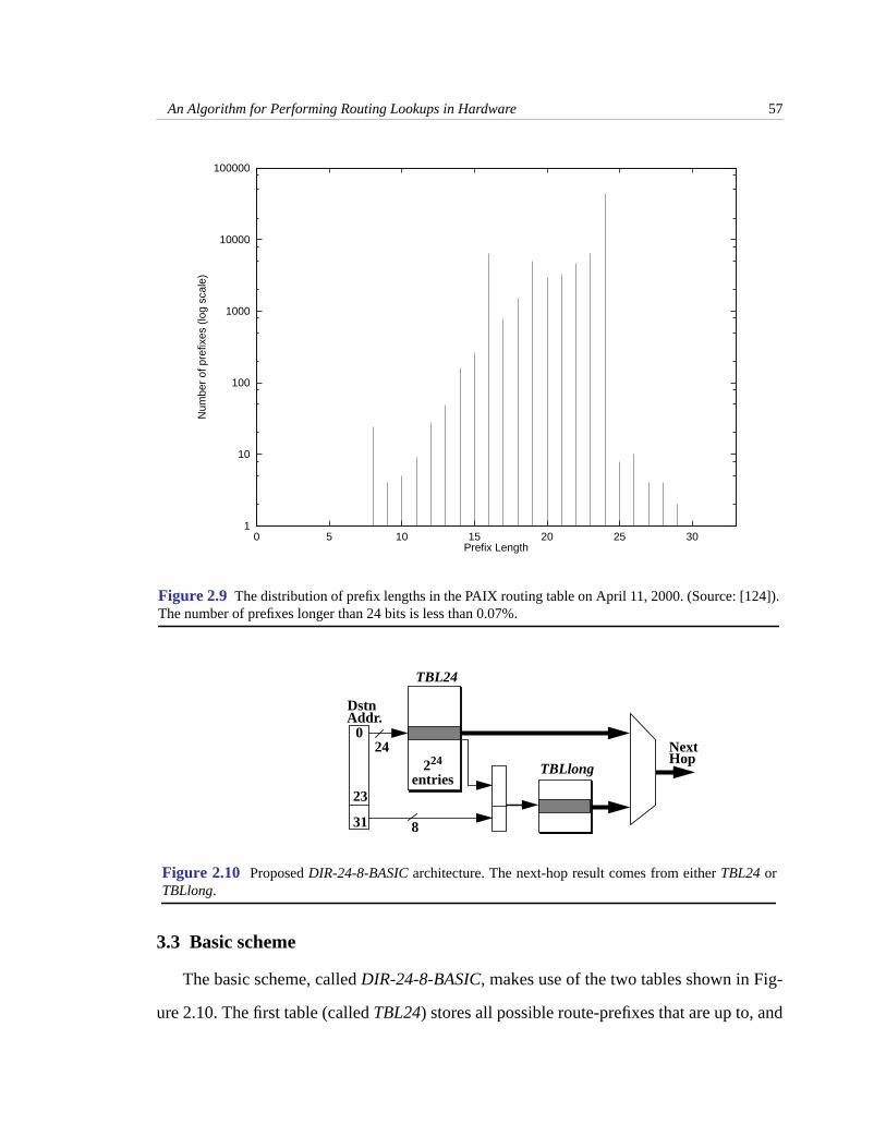
1. Because of route-aggregation at intermediate routers (mentioned in Chapter 1),routing tables at higher speed backbone routers containfew entries with prefixeslonger than 24-bits. This is verified by a plot of prefix length distribution of thebackbone routing tables taken from the PAIX NAP on April 11, 2000 [124], asshown in Figure 2.9 (note the logarithmic scale on the y-axis). In this example,99.93% of the prefixes are 24-bits or less. A similar prefix length distribution isseen in the routing tables at other backbone routers. Also, this distribution hashardly changed over time.
2. DRAM memory is cheap, and continues to get cheaper by a factor of approxi-mately two every year. 64 Mbytes of SDRAM (synchronous DRAM) cost around$50 in April 2000 [129]. Memory densities are following Moore’s law and dou-bling every eighteen months. The net result is that a large amount of memory isavailable at low cost. This observation provides the motivation for trading offlarge amounts of memory for lookup speed. This is in contrast to most of the pre-vious work (mentioned in Section 2.2) that seeks to minimize the storage require-ments of the data structure.
An Algorithm for Performing Routing Lookups in Hardware 57
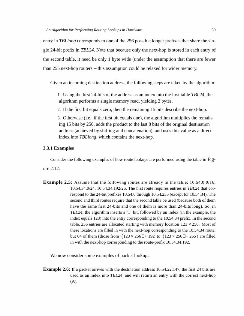
3.3 Basic scheme
The basic scheme, calledDIR-24-8-BASIC, makes use of the two tables shown in Fig-
ure 2.10. The first table (calledTBL24) stores all possible route-prefixes that are up to, and
Figure 2.9 The distribution of prefix lengths in the PAIX routing table on April 11, 2000. (Source: [124]).The number of prefixes longer than 24 bits is less than 0.07%.
1
10
100
1000
10000
100000
0 5 10 15 20 25 30
Num
ber
of p
refix
es (
log
scal
e)
Prefix Length
Figure 2.10 ProposedDIR-24-8-BASIC architecture. The next-hop result comes from eitherTBL24 orTBLlong.
TBL24
TBLlong
0
23
31
DstnAddr.
24
8
NextHop224
entries

An Algorithm for Performing Routing Lookups in Hardware 58
including, 24-bits long. This table has 224 entries, addressed from 0 (corresponding to the
24-bits being 0.0.0) to (255.255.255). Each entry inTBL24 has the format shown
in Figure 2.11. The second table (TBLlong) stores all route-prefixes in the routing table
that are longer than 24-bits. This scheme can be viewed as a fixed-stride trie with two lev-
els: the first level with a stride of 24, and the second level with a stride of 8. We will refer
to this as a (24,8) split of the 32-bit binary trie. In this sense, the scheme can be viewed as
a special case of the general scheme of expanding tries [93].
A prefix,X, is stored in the following manner: ifX is less than or equal to 24 bits long,
it need only be stored inTBL24: the first bit of such an entry is set to zero to indicate that
the remaining 15 bits designate the next-hop. If, on the other hand, prefixX is longer than
24 bits, the first bit of the entry indexed by the first 24 bits ofX in TBL24 is set to one to
indicate that the remaining 15 bits contain a pointer to a set of entries inTBLlong.
In effect, route-prefixes shorter than 24-bits are expanded; e.g. the route-prefix
128.23.0.0/16 will have entries associated with it inTBL24, ranging from
the memory address 128.23.0 through 128.23.255. All 256 entries will have exactly the
same contents (the next-hop corresponding to the route-prefix 128.23.0.0/16). By using
memory inefficiently, we can find the next-hop information within one memory access.
TBLlong contains all route-prefixes that are longer than 24 bits. Each 24-bit prefix that
has at least one route longer than 24 bits is allocated entries inTBLlong. Each
224
1–
1 bit 15 bits
0 Next-hop
1 Index into 2nd table TBLlong
If longest prefix with this 24-bit prefix is < 25 bits long:
If longest prefix with this 24 bits prefix is > 24 bits long:
15 bits1 bit
Figure 2.11 TBL24 entry format
224 16–
256=
28
256=
An Algorithm for Performing Routing Lookups in Hardware 59
entry inTBLlong corresponds to one of the 256 possible longer prefixes that share the sin-
gle 24-bit prefix inTBL24. Note that because only the next-hop is stored in each entry of
the second table, it need be only 1 byte wide (under the assumption that there are fewer
than 255 next-hop routers– this assumption could be relaxed for wider memory.
Given an incoming destination address, the following steps are taken by the algorithm:
1. Using the first 24-bits of the address as an index into the first tableTBL24, thealgorithm performs a single memory read, yielding 2 bytes.
2. If the first bit equals zero, then the remaining 15 bits describe the next-hop.
3. Otherwise (i.e., if the first bit equals one), the algorithm multiplies the remain-ing 15 bits by 256, adds the product to the last 8 bits of the original destinationaddress (achieved by shifting and concatenation), and uses this value as a directindex intoTBLlong, which contains the next-hop.
3.3.1 Examples
Consider the following examples of how route lookups are performed using the table inFig-
ure 2.12.
Example 2.5: Assume that the following routes are already in the table: 10.54.0.0/16,10.54.34.0/24, 10.54.34.192/26. The first route requires entries inTBL24 that cor-respond to the 24-bit prefixes 10.54.0 through 10.54.255 (except for 10.54.34). Thesecond and third routes require that the second table be used (because both of themhave the same first 24-bits and one of them is more than 24-bits long). So, inTBL24, the algorithm inserts a ‘1’ bit, followed by an index (in the example, theindex equals 123) into the entry corresponding to the 10.54.34 prefix. In the secondtable, 256 entries are allocated starting with memory location . Most ofthese locations are filled in with the next-hop corresponding to the 10.54.34 route,but 64 of them (those from to ) are filledin with the next-hop corresponding to the route-prefix 10.54.34.192.
We now consider some examples of packet lookups.
Example 2.6:If a packet arrives with the destination address 10.54.22.147, the first 24 bits areused as an index intoTBL24, and will return an entry with the correct next-hop(A).
123 256×
123 256×( ) 192+ 123 256×( ) 255+

An Algorithm for Performing Routing Lookups in Hardware 60
Example 2.7:If a packet arrives with the destination address 10.54.34.14, the first 24 bits areused as an index into the first table, which indicates that the second table must beconsulted. The lower 15 bits of theTBL24 entry (123 in this example) are com-bined with the lower 8 bits of the destination address and used as an index into thesecond table. After two memory accesses, the table returns the next-hop (B).
Example 2.8:If a packet arrives with the destination address 10.54.34.194,TBL24 indicates thatTBLlong must be consulted, and the lower 15 bits of theTBL24 entry are combinedwith the lower 8 bits of the address to form an index into the second table. Thistime the next-hop (C) associated with the prefix 10.54.34.192/26 (C) is returned.
The size of second memory that stores the tableTBLlong depends on the number of
routes longer than 24 bits required to be supported. For example, the second memory
needs to be 1 Mbyte in size for 4096 routes longer than 24 bits (to be precise, 4096 routes
that are longer than 24 bits and have distinct 24-bit prefixes). We see from Figure 2.9 that
the number of routes with length above 24 is much smaller than 4096 (only 31 for this
Figure 2.12 Example with three prefixes.
Entry
10.54.0
10.54.34
10.55.0
10.53.255
10.54.1
10.54.33
10.54.35
10.54.255
0
1
0
0
0
0
A
123
A
A
A
A
TBL24
123*256
123*256+1
123*256+2
123*256+191
123*256+192
123*256+193
123*256+255
124*256
B
C
B
C
C
B
C
B
TBLlong
Entry
256 entriesallocated to
10.54.34
Number Contents Number Contents Forwarding Table
(10.54.0.0/16, A)(10.54.34.0/24, B)(10.54.34.192/26, C)
prefix

An Algorithm for Performing Routing Lookups in Hardware 61
router). Because 15 bits are used to index intoTBLlong, 32K distinct 24-bit-prefixed long
routes with prefixes longer than 24 bits can be supported with enough memory.
As a summary, we now review some of the pros and cons associated with theDIR-24-
8-BASICscheme.
Pros
1. Except for the limit on the number of distinct 24-bit-prefixed routes with lengthgreater than 24 bits, this infrastructure will support an unlimited number of route-prefixes.
2. The design is well suited to hardware implementation. A reference implementa-tion could, for example, storeTBL24 in either off-chip, or embedded SDRAM andTBLlong in on-chip SRAM or embedded-DRAM. Although (in general) twomemory accesses are required, these accesses are in separate memories, allowingthe scheme to be pipelined. When pipelined, 20 million packets per second can beprocessed with 50ns DRAM. The lookup time is thus equal to one memory accesstime.
3. The total cost of memory in this scheme is the cost of 33 Mbytes of DRAM (32Mbytes forTBL24 and 1 Mbyte forTBLlong), assumingTBLlong is also kept inDRAM. No special memory architectures are required.
Cons
1. Memory is used inefficiently.
2. Insertion and deletion of routes from this table may require many memoryaccesses, and a large overhead to the central processor. This is discussed in detailin Section 5.
4 Variations of the basic scheme
The basic scheme,DIR-24-8-BASIC, consumes a large amount of memory. This sec-
tion proposes variations of the basic scheme with lower storage requirements, and
explores the trade-off between storage requirements and the number of pipelined memory
accesses.

An Algorithm for Performing Routing Lookups in Hardware 62
4.1 SchemeDIR-24-8-INT: adding an intermediate “length” table
This variation is based on the observation that very few prefixes in a forwarding table
that are longer than 24 bits are a full 32 bits long. For example, there are no 32-bit prefixes
in the prefix-length distribution shown in Figure 2.9. The basic scheme,DIR-24-8-BASIC,
allocates an entire block of 256 entries in tableTBLlong for each prefix longer than 24
bits. This could waste memory — for example, a 26-bit prefix requires only
entries, but is allocated 256TBLlong entries in the basic scheme.
The storage efficiency (amount of memory required per prefix) can be improved by
using an additional level of indirection. This variation of the basic scheme, calledDIR-24-
8-INT, maintains an additional “intermediate” table,TBLint,as shown in Figure 2.13. An
entry inTBL24 that pointed to an entry inTBLlong in the basic scheme now points to an
entry inTBLint. Each entry inTBLint corresponds to the unique 24-bit prefix represented
by theTBL24 entry that points to it. Therefore,TBLint needs to be entries deep to sup-
port prefixes that are longer than 24 bits and have distinct 24-bit prefixes.
Assume that an entry, , ofTBLint corresponds to the 24-bit prefix . As shown in
Figure 2.14, entry contains a 21-bit index field into tableTBLlong, and a 3-bitprefix-
length field. The index field stores an absolute memory address inTBLlongat which the
set ofTBLlong entries associated with begins. This set ofTBLlong entries was always of
size 256 in the basic scheme, but could be smaller in this schemeDIR-24-8-INT. The size
of this set is encoded in theprefix-length field of entry . Theprefix-length field indicates
the longest prefix in the forwarding table among the set of prefixes that have the first 24-
bits identical to . Three bits are sufficient because the length of this prefix must be in the
range 25-32. Theprefix-length field thus indicates how many entries inTBLlong are allo-
cated to this 24-bit prefix . For example, if the longest prefix is 30 bits long, then thepre-
226 24–
4=
M
M
e q
e
q
e
q
q

An Algorithm for Performing Routing Lookups in Hardware 63
fix-length field will store , andTBLlong will have entries allocated to
the 24-bit prefix .
Example 2.9:(see Figure 2.13) Assume that two prefixes 10.78.45.128/26 and 10.78.45.132/30are stored in the table. The entry in tableTBL24 corresponding to 10.78.45 willcontain an index to an entry inTBLint (the index equals 567 in this example). Entry567 inTBLint indicates a length of 6, and an index intoTBLlong (the index equals325 in the example) pointing to 64 entries. One of these entries, the 33rd (bits num-bered 25 to 30 of prefix 10.78.45.132/30 are 100001, i.e., 33), contains the next-hop for the 10.78.45.132/30 route-prefix. Entry 32 and entries 34 through 47 (i.e.,entries indicated by 10**** except 100001) contain the next-hop for the
30 24– 6= 26 64=
q
567 6 325
LenEntry#
325
325+1
325+32
325+33
325+34
325+31
325+47
325+48
325+63
B
A
A
A
Figure 2.13 SchemeDIR-24-8-INT
TBL24
TBLlong
TBLint
64 e
ntrie
s al
loca
ted
to 1
0.78
.45
prefi
x
Entry # Contents
Index
10.78.45 1 567
Entry # Contents
Forwarding Table
(10.78.45.128/26, A)(10.78.45.132/30, B)
index into 2nd table max length
3 bits21 bits
Figure 2.14 TBLint entry format.

An Algorithm for Performing Routing Lookups in Hardware 64
10.78.45.128/26 route. The other entries contain the next-hop value for the defaultroute.
The schemeDIR-24-8-INT improves utilization of tableTBLlong, by an amount that
depends on the distribution of the length of prefixes that are longer than 24-bits. For exam-
ple, if the lengths of such prefixes were uniformly distributed in the range 25 to 32, 16K
such prefixes could be stored in a total of 1.05 Mbytes of memory. This is becauseTBLint
wou ld requ i re , and TBL long wou ld requ i re
of memory. In contrast, the basic scheme would
require to store the same number of prefixes. However, the mod-
ification to the basic scheme comes at the cost of an additional memory access, extending
the pipeline to three stages.
4.2 Multiple table scheme
The modifications that we consider next split the 32-bit space into smaller subspaces
so as to decrease the storage requirements. This can be viewed as a special case of the gen-
eralized technique of trie expansion discussed in Section 2.2.2. However, the objective
here is to focus on a hardware implementation, and hence on the constraints posed by the
worst-case scenarios, as opposed to generating an optimal sequence of strides that mini-
mizes the storage consumption for a given forwarding table.
The first scheme, calledDIR-21-3, extends the basic schemeDIR-24-8-BASICto use
three smaller tables instead of one large table (TBL24) and one small table (TBLlong). As
an example, tablesTBL24 andTBLlong in schemeDIR-24-8-BASIC are replaced by a 221
entry table (the “first” table,TBLfirst21), another 221 entry table (the “second” table,
TBLsec21), and a 220 entry table (the “third” table,TBLthird20). The first 21 bits of the
packet’s destination address are used to index intoTBLfirst21, which has entries of width
16K 3B× 0.05MB≈
16K( ) 2i
1…8∑
8⁄× 1byte× 1MB≈
16K 28× 1byte× 4MB=

An Algorithm for Performing Routing Lookups in Hardware 65
19 bits.1 As before, the first bit of the entry will indicate whether the rest of the entry is
used as the next-hop identifier or as an index into another table (TBLsec21 in this scheme).
If the rest of the entry inTBLfirst21 is used as an index into another table, this 18-bit
index is concatenated with the next 3 bits (bit numbers 22 through 24) of the packet’s des-
tination address, and is used as an index intoTBLsec21. TBLsec21 has entries of width 13
bits. As before, the first bit indicates whether the remaining 12-bits can be considered as a
next-hop identifier, or as an index into the third table (TBLthird20). If used as an index, the
12 bits are concatenated with the last 8 bits of the packet’s destination address, to index
into TBLthird20. TBLthird20, like TBLlong, contains entries of width 8 bits, storing the
next-hop identifier.
The schemeDIR-21-3 corresponds to a (21,3,8) split of the trie. It could be general-
ized to theDIR-n-m scheme which corresponds to a split of the trie for
general and . The three tables inDIR-n-m are shown in Figure 2.15.
1. Word-lengths, such as those which are not multiples of 4, 8, or 16, are not commonly available in off-chip memories.We will ignore this issue in our examples.
n m 32 n– m–, ,( )
n m
Figure 2.15 Three table scheme in the worst case, where the prefix is longer than (n+m) bits long. In thiscase, all three levels must be used, as shown.
First (2n entry) table
destination address destination address as index.
Use index “j” concatenatedwith last 32-n-m bits of destinationaddress as index into this table.
Use firstn bits of
i 2m×
Second table
Use index “i” concatenatedwith next m bits of
as index.
j concatenatedwith last32-n-m bits
Next-hopi concatenatedwith nextm bits
Index j1first n bits Index i1
Entry # Contents Entry # Contents Entry # Contents
TBLfirst21 TBLsec20Third table TBLthird20

An Algorithm for Performing Routing Lookups in Hardware 66
DIR-21-3 has the advantage of requir ing a smaller amount of memory:
. One disadvantage of this scheme is an increase
in the number of pipeline stages, and hence the pipeline complexity. Another disadvantage
is that this scheme puts another constraint on the number of prefixes — in addition to only
supporting 4096 routes of length 25 or greater with distinct 24-bit prefixes, the scheme
supports only prefixes of length 22 or greater with distinct 21-bit prefixes. It is to be
noted, however, that the decreased storage requirements enableDIR-21-3 to be readily
implemented using on-chip embedded-DRAM.1
The scheme can be extended to an arbitrary number of table levels between 1 and 32 at
the cost of an additional constraint per table level. This is shown in Table 2.4, where we
assume that at each level, only prefixes can be accommodated by the next higher level
memory table, except the last table, which we assume supports only 4096 prefixes.
Although not shown in the table, memory requirements vary significantly (for the same
number of levels) with the choice of the actual number of bits to use per level. Table 2.4
shows only thelowest memory requirement for a given number of levels. For example, a
three level (16,8,8) split would require 105 Mbytes with the same constraints. As Table
1. IBM offers 128 Mb embedded DRAM of total size 113 mm2 using 0.18 u semiconductor process technology [122] atthe time of writing.
TABLE 2.4. Memory required as a function of the number of levels.
Number oflevels
Bits used per levelMinimum memory
requirement(Mbytes)
3 21, 3 and 8 9
4 20, 2, 2 and 8 7
5 20, 1, 1, 2 and 8 7
6 19, 1, 1, 1, 2 and 8 7
221 19⋅( ) 221 13⋅( ) 220 8⋅( )+ + 9MB=
218
218

An Algorithm for Performing Routing Lookups in Hardware 67
2.4 shows, increasing the number of levels achieves diminishing memory savings, coupled
with increased hardware logic complexity to manage the deeper pipeline.
5 Routing table updates
Recall from Section 1.1 of Chapter 1 that as the topology of the network changes, new
routing information is disseminated among the routers, leading to changes in routing
tables. As a result, one or more entries must be added, updated, or deleted from the for-
warding table. The action of modifying the table can interfere with the process of forward-
ing packets– hence, we need to consider the frequency and overhead caused by changes
to the table. This section proposes several techniques for updating the forwarding table
and evaluates them on the basis of (1) overhead to the central processor, and (2) number of
memory accesses required per routing table update.
Measurements and anecdotal evidence suggest that routing tables change frequently
[47]. Trace data collected from a major ISP backbone router1 indicates that a few hundred
updates can occur per second. A potential drawback of the 16-million entryDIR-24-8-
BASIC scheme is that changing a single prefix can affect a large number of entries in the
table. For instance, inserting an 8-bit prefix in an empty forwarding table may require
changes to consecutive memory entries. With the trace data, if every routing table
change affected entries, it would lead to millions of entry changes per second!2
Because longer prefixes create “holes” in shorter prefixes, the memory entries required
to be changed on a prefix update may not be at consecutive memory locations. This is
1. The router is part of the Sprint network running BGP-4. The trace had a total of 3737 BGP routing updates, with anaverage of 1.04 updates per second and a maximum of 291 updates per second.
2. In practice, of course, the number of 8-bit prefixes is limited to just 256, and it is extremely unlikely that they will allchange at the same time.
216
216

An Algorithm for Performing Routing Lookups in Hardware 68
illustrated in Figure 2.16 where a route-prefix of 10.45.0.0/16 exists in the forwarding
table. If the new route-prefix 10.0.0.0/8 is added to the table, we need to modify only a
portion of the 216 entries described by the 10.0.0.0/8 route, and leave the 10.45.0.0/16
“hole” unmodified.
We will only focus on techniques to update the largeTBL24 table in theDIR-24-8-
BASICscheme. The smallerTBLlong table requires less frequent updates and is ignored in
this discussion.
5.1 Dual memory banks
This technique uses two distinct ‘banks’ of memory– resulting in a simple but expen-
sive solution. Periodically, the processor creates and downloads a new forwarding table to
one bank of memory. During this time (which in general will take much longer than one
lookup time), the other bank of memory is used for forwarding. Banks are switched when
the new bank is ready. This provides a mechanism for the processor to update the tables in
a simple and timely manner, and has been used in at least one high-performance router
[76].
“Hole” in 10/8
Figure 2.16 Holes created by longer prefixes require the update algorithm to be careful to avoid themwhile updating a shorter prefix.
caused by 10.45.0.0/16
0.0.0 10.0.0 10.45.0 10.45.255 10.255.255 255.255.255
10.0.0.0/810.45.0.0/16

An Algorithm for Performing Routing Lookups in Hardware 69
5.2 Single memory bank
It is possible to avoid doubling the memory by making the central processor do more
work. This is typically achieved as follows: the processor keeps a software copy of the
hardware memory contents and calculates the hardware memory locations that need to be
modified on a prefix update. The processor then sends appropriate instructions to the hard-
ware to change memory contents at the identified locations. An important issue to con-
sider is the number of instructions that must flow from the processor to the hardware for
every prefix update. If the number of instructions is too high, performance will become
limited by the processor. We now describe three different update techniques, and compare
their performance when measured by the number of update instructions that the processor
must generate.
5.2.1 Update mechanism 1:Row-update
In this technique, the processor sends one instruction for each modified memory loca-
tion. For example, if a prefix of 10/8 is added to a table that already has a prefix of
10.45.0.0/16 installed, the processor will send separate instructions,
each instructing the hardware to change the contents of the corresponding memory loca-
tions.
While this technique is simple to implement in hardware, it places a huge burden on
the processor, as experimental results described later in this section show.
5.2.2 Update mechanism 2:Subrange-update
The presence of “holes” partitions the range of updated entries into a series of inter-
vals, which we call subranges. Instead of sending one instruction per memory entry, the
processor can find the bounds of each subrange, and send one instruction per subrange.
The instructions from the processor to the linecards are now of the form: “change mem-
ory entries starting at memory address to have the new contents” where is the
65536 256– 65280=
X
Y Z X

An Algorithm for Performing Routing Lookups in Hardware 70
number of entries in the subrange, is the starting entry number, and is the new next-
hop identifier. In our example above, the updates caused by the addition of a new route-
prefix in this technique are performed with just two instructions: the first instruction
updating entries 10.0.0 through 10.44.255, and the second 10.46.0 through 10.255.255.
This update technique works well when entries have few “holes”. However, many
instructions are still required in the worst case: it is possible (though unlikely) in the
pathological case that every other entry needs to be updated. Hence, an 8-bit prefix would
require up to 32,768 update instructions in the worst case.
5.2.3 Update mechanism 3:One-instruction-update
This technique requires only one instruction from the processor for each updated pre-
fix, regardless of the number of holes. This is achieved by simply including an additional
5-bit length field in every memory entry indicating the length of the prefix to which the
entry belongs. The hardware now uses this information to decide whether a memory entry
needs to be modified on an update instruction from the processor.
Consider again the example of a routing table containing the prefixes 10.45.0.0/16 and
10.0.0.0/8. The entries in the “hole” created by the 10.45.0.0/16 prefix contain the value
16 in the 5-bit length field; the other entries associated with the 10.0.0.0/8 prefix contain
the value 8. Hence, the processor only needs to send a single instruction for each prefix
update. This instruction is of the form: “insert a -bit long prefix starting in memory at
to have the new contents”; or “delete the -bit long prefix starting in memory at .”
The hardware then examines entries beginning with entry . On an insertion, each
entry whose length field is less than or equal to is updated to contain the value . Those
entries with length field greater than are left unchanged. As a result, “holes” are skipped
within the updated range. A delete operation proceeds similarly.
Y Z
Y X
Z Y X
224 Y– X
Y Z
Y

An Algorithm for Performing Routing Lookups in Hardware 71
This update technique reduces overhead at the cost of an additional 5-bit field that
needs to be added to all 16 million entries in the table, which is an additional 10 Mbyte
(about 30%) of memory. Also, unlike the Row- and Subrange-update techniques, this
technique requires a read-modify-write operation for each scanned entry. This can be
reduced to a parallel read and write if the marker field is stored in a separate physical
memory.
5.2.4 Update mechanism 4: Optimized One-instruction-update
This update mechanism eliminates the need to store a length field in each memory
entry, and still requires the processor to send only one instruction to the hardware. It does
so by utilizing structural properties of prefixes, as explained below.
First note that for any two distinct prefixes, either one is completely contained in the
other, or the two prefixes have no entries in common. This structure is very similar to that
of parenthetical expressions where the scope of an expression is delimited by balanced
opening and closing parentheses: for example, the characters “{” and “}” used to delimit
expressions in the ‘C’ programming language. Figure 2.17 shows an example with three
“nested” prefixes.
The hardware needs to know the length of the prefix that a memory entry belongs to
when deciding whether or not the memory entry needs to be modified. In the previous
{
{
{ }
}
}
Figure 2.17 Example of the balanced parentheses property of prefixes.
10.0.0.0 10.255.255.255
10.1.192.0 10.1.192.255
10.1.0.0 10.1.255.255
Depth 3.........................
Depth 2...........
Depth 1....

An Algorithm for Performing Routing Lookups in Hardware 72
One-instruction-update mechanism, the length is explicitly stored in each memory entry.
However, the balanced parentheses property of prefixes allows the calculation of the nest-
ing depth of a memory entry as follows. The central processor provides the hardware with
the location of thefirst memory entry to be updated. Assume that this entry is at a nesting
depth . The hardware performs a sequential scan of the memory, and keeps track of the
number of opening and closing parentheses seen so far in the scan. Since each opening
parenthesis increases the nesting depth, and each closing parenthesis decreases the nesting
depth, the hardware can calculate the nesting depth of each memory entry, and modify it if
the depth is . The sequential scan stops when the hardware encounters the closing paren-
thesis at nesting depth .
Under this technique, each entry inTBL24 is categorized as one of the following
types: an opening parenthesis (start of prefix), a closing parenthesis (end of prefix), no
parenthesis (middle of prefix), or both an opening and closing parenthesis (if the prefix
contains only a single entry). This information is represented by a 2-bit marker field in
each entry.
Care must be taken when a single entry inTBL24 corresponds to the start or end of
multiple prefixes, as shown in Figure 2.18. A 2-bit encoding is not sufficient to describe all
d
d
d
Depth = 4
{{ }
}
}
}{
{
Figure 2.18 This figure shows five prefixes, one each at nesting depths 1,2 and 4; and two prefixes atdepth 3. The dotted lines show those portions of ranges represented by prefixes that are also occupied byranges of longer prefixes. Prefixes at depths 2, 3 and 4 start at the same memory entry A, and thecorresponding parenthesis markers are moved appropriately.
A B
Depth = 3
Depth = 2
Depth = 1
} {

An Algorithm for Performing Routing Lookups in Hardware 73
the prefixes that begin and end at a memory location ‘A.’ The problem is readily fixed by
shifting the opening and closing markers to the start (end) of the first (last) entry in mem-
ory that the prefix affects. The update algorithm is described in detail below.
We first define two terms– prefix-start (PS)andmemory-start (MS) of a prefix. ,
the prefix-start of a prefix , is defined to be the memory entry where the prefix issup-
posed to start in memory (for example, both 10.0.0.0/8 and 10.0.0.0/24 are supposed to
start at 10.0.0). , the memory start of a prefix , is the first memory entry which
actually has the entry corresponding to prefix in memory. may or may not be the
same as . These two entries are different for a prefix if and only if a longer prefix
than starts at . In the same way, we define the prefix- and memory-ends (PE and
ME) of a prefix. Hence, is the first memory entry which has as the deepest (long-
est) prefix covering it, and is the last.
Example 2.10:If we have prefixes p1(10/8) and p2(10.0.0.0/24); = 10.0.0; = 10.0.1; = 10.0.0; = 10.255.255.255,
= 10.0.0.255.
PS p( )
p
MS p( ) p
p MS p( )
PS p( ) p
p PS p( )
MS p( ) p
ME p( )
10.0.0.0/16
10.0/20
10.0.0/2210.255.252/22(p4)
10.255.240/20
10.255.240/24 (p5)
(p1)
(p2)
(p6)
(p7)
PS(p1)=PS(p2)=PS(p3)
MS(p1)PE(p4)
ME(p1)
10.255.254/23
A B E
(p3)
C D
PE(p3) MS(p2)
PE(p2)
PS(p4)
PS(p7)=PS(p5) PE(p5)
MS(p7)
ME(p7)PS(p6)
PE(p7)=PE(p1)=PE(p6)
S E S E S S E S/E SE SE E
Figure 2.19 Definition of the prefix and memory start and end of prefixes. Underlined PS (PE) indicatesthat this prefix-start (prefix-end) is also the memory-start (memory-end) marker.
PS p1( ) PS p2( )=MS p1( ) MS p2( ) ME p1( ) PE p1( )=ME p2( ) PE p2( )=

An Algorithm for Performing Routing Lookups in Hardware 74
Example 2.11:Figure 2.19 shows another detailed example with several route-prefixes, alongwith their prefix and memory starts and ends.
Now, instead of putting the start/end markers on the prefix start/end entries, this update
mechanism puts themarkers on the memory start/end entries. Thus when the hardware
encounters a marker, it can uniquely determine that exactlyone prefix has started or
ended. This takes care of the problem that multiple prefixes may start or end at the same
memory location. The exact algorithm can now be formalized:
Assume that the new update is to be carried out starting with memory entry for a -
bit prefix, , with new next-hop . First, the processor determines the first memory entry,
say , after whose next-hop should change to as a result of this update. The proces-
sor then issues one instructionUpdate(m,Y,Z) to the hardware, which then executes the
steps shown in Figure 2.20.
The algorithm can be intuitively understood as follows: if the hardware encounters a
start-marker while scanning the memory in order to add a new prefix, it knows that it is
entering a deeper prefix and stops updating memory until it again reaches the prefix at
X Y
p Z
m X Z
1. Initialize a depth-counter ( ) to zero.
2. Write the start-marker on .
3. Scan each memory entry starting with , until either reaches
zero, or, is reached (i.e., the memory entry just scanned
has a ‘1’ in its last (24-Y) bits). At each location, perform in
order: (a) If entry has start marker, increment by 1.(b) If
equals 1, update this entry to denote the next-hop Z. (c) If
entry has an end-marker, decrement by 1.
4. After completion of (3), put an end marker on the last memory
entry scanned. If a total of only one memory entry ( ) was
scanned, put a start-and-end marker on .
DC
m
m DC
PE p( )
DC
DC
DC
m
m
Figure 2.20 The optimized One-instruction-update algorithm executingUpdate(m,Y,Z).

An Algorithm for Performing Routing Lookups in Hardware 75
which it started. The end condition guarantees that any start-marker it sees will mark the
start of a deeper prefix than (and is hence not to be updated). A formal proof of correct-
ness of this algorithm is provided in Appendix A.
If a prefix is updated, the start and end markers may need to be changed. For instance,
if the entry 10.255.240/20 (p7) is deleted in Figure 2.19, the end-marker for p1 has to be
moved from point D to point E. Again this can be achieved in one instruction if the pro-
cessor sends an indication of whether to move the start/end marker in conjunction with the
relevant update instruction. Note that at most one start/end marker of any other prefix
(apart from the one which is being updated) needs to be changed. This observation enables
the algorithm to achieve all updates (additions/deletions/modifications) in only one pro-
cessor instruction.
5.3 Simulation results
The behavior of each update technique was simulated with the same sequence of rout-
ing updates collected from a backbone router. The trace had a total of 3737 BGP routing
updates, with an average of 1.04 updates per second and a maximum of 291 updates per
second. The simulation results are shown in Table 2.5.1
1. For the one-instruction-update (optimized technique) we assume that the extra 2-bits to store the opening/closingmarker fields mentioned above arenot stored in a separate memory.
TABLE 2.5. Simulation results of different routing table update techniques.
UpdateTechnique
Number of instructionsfrom processor persecond (avg/max)
Number of memoryaccesses per second (avg/
max)
Row 43.4/17545 43.4/17545
Subrange 1.14/303 43.4/17545
One-instruction 1.04/291 115.3/40415
Y

An Algorithm for Performing Routing Lookups in Hardware 76
The results corroborate the intuition that the row-update technique puts a large burden
on the processor. At the other extreme, the one-instruction-update technique is optimal in
terms of the number of instructions required to be sent by the processor. But unless a sep-
arate marker memory is used, the one-instruction technique requires more than twice as
many memory accesses as the other update techniques. However, this still represents less
than 0.2% of the routing lookup capacity achievable by the lookup algorithm. This simula-
tion suggests that the subrange-update technique performs well by both measures. The
small number of instructions from the processor can be attributed to the fact that the rout-
ing table contained few holes. This is to be expected for most routing tables in the near
term. But it is too early to tell whether routing tables will become more fragmented and
contain more holes in the future.
6 Conclusions and summary of contributions
The main contribution of this chapter is an algorithm to perform one IPv4 routing
lookup operation in dedicated hardware in the time that it takes to execute a single mem-
ory access (when pipelined), and no more than two memory accesses. With the throughput
of one memory access rate, approximately 20 million lookups can be completed per sec-
ond with 50 ns DRAMs (or even faster with upcoming embedded-DRAM technology).
Furthermore, this is the only algorithm that we know of that supports an unlimited
number of prefixes that are less than or equal to 24 bits long. Since a very small proportion
(typically less than 0.1%) of all prefixes in a routing table are longer than 24 bits (see Sec-
tion 3.2), this algorithm supports, practically speaking, routing tables of unlimited size.
The algorithm operates by expanding the prefixes and trading-off cheap memory for
speed. Yet, the total memory cost today is less than $25, and will (presumably) continue to
halve each year. For those applications where low cost is paramount, this chapter

An Algorithm for Performing Routing Lookups in Hardware 77
described several multi-level variations on the basic scheme that utilize memory more
efficiently.
Another contribution of this chapter is the design of several hardware update mecha-
nisms. The chapter proposed and evaluated two update mechanisms (Subrange-update and
One-instruction-update) that perform efficiently and quickly in hardware, with little bur-
den on the routing processor and low interference to the normal forwarding function.

An Algorithm for Performing Routing Lookups in Hardware 78